1. Introduction
The low-altitude economy, as an emerging economic model, has drawn significant attention by aggregating innovative resources and demonstrating substantial development potential [
1]. Quadrotor unmanned aerial vehicles (UAVs), with their unique capabilities for hovering and vertical takeoff and landing, have found extensive applications in diverse industries [
2], including military reconnaissance, disaster rescue, high-voltage power line inspection, precision agriculture [
3], and remote sensing [
4]. Despite their structural simplicity, cost-effectiveness, and agile flight performance, quadrotors present challenges in control due to the strong coupling and nonlinear dynamics inherent in their six-degree-of-freedom (6-DOF) attitude system—comprising three translational and three rotational motions—controlled by only four input channels [
5]. Moreover, complex external disturbances further degrade attitude tracking accuracy [
6].
To address the challenges associated with quadcopter attitude tracking control, researchers worldwide have conducted extensive studies, categorizing existing methods into two major approaches. The first category assumes that the UAV’s attitude does not change drastically, using a small-disturbance linearization model [
7]. This method effectively ensures asymptotic tracking of attitude commands under small disturbance conditions. However, when the attitude changes significantly, the linear model fails to accurately reflect the system’s dynamic characteristics [
8]. To overcome this limitation, the second approach employs nonlinear models for controller design [
9]. For instance, Wang et al. [
10] combined this with the backstepping control method, which effectively reduced overshoot by 47.79%. Tian et al. [
11] have designed finite-time control schemes based on power integration technology, addressing both known and unknown states and achieving finite-time tracking of attitude commands. In this paper, we designed a controller using power integration technology for known states, improving tracking accuracy by 40% compared to traditional methods. We further considered scenarios with incomplete state observation and designed a state observer [
12] combined with a power integration controller, achieving tracking error within ±0.1 degrees even with 1% measurement noise, significantly enhancing system robustness. Most of these methods rely on the nominal model of the system [
13], and while they effectively suppress disturbances when their energy is small, they struggle to handle more complex disturbances arising from a complicated flight environment. UAVs often encounter multi-source disturbances (such as gusts, friction, unmodeled dynamics, and aerodynamic parameter variations) during flight, which typically do not meet the condition of small disturbance energy, making it difficult to suppress such disturbances by relying solely on the robustness of the control algorithm [
14].
In response to these issues, active disturbance rejection control (ADRC) methods based on disturbance observers have emerged [
15]. This approach estimates disturbances by designing disturbance observers and integrates them into the controller in a feedforward manner to directly counteract their effects. For example, Zhao et al. [
16] proposed a fast non-singular terminal sliding mode attitude control scheme that achieves finite-time attitude control. However, the design of sliding mode control is highly dependent on an accurate system model, and the tuning process for control parameters is relatively complex, limiting its practical application [
17]. The ADRC has gained significant attention due to its prominent advantages: it has low dependency on accurate system models, which greatly reduces reliance on complex dynamics modeling of the controlled object; it features excellent dynamic response characteristics, allowing rapid tracking of reference signals even when input changes suddenly; it delivers stable and chattering-free control output, avoiding adverse impacts on actuator service life and control precision; it enables relatively simple parameter adjustment, lowering the technical threshold for practical deployment; and it has inherent strong anti-disturbance capability, as it directly offsets external disturbances and internal uncertainties through feedforward compensation of observer-estimated disturbance values [
18]. In recent years, scholars have combined various disturbance observer design techniques to create active disturbance rejection tracking controllers for quadcopter UAVs in disturbed environments. Wang et al. [
19] used dual-loop linear active disturbance rejection control (LADRC) to control UAV height and attitude, demonstrating good anti-disturbance performance in simulations. Wang et al. [
20] proposed an adaptive composite ADRC attitude controller that addressed wind disturbances, payload disturbances, and propeller faults. A fuzzy controller [
21] was combined with ADRC, further improving control performance. Although these studies have offered valuable insights into quadcopter attitude control, limitations remain in managing complex coupling and multi-source disturbances [
22].
To further extend the range of disturbances that can be addressed while reducing the complexity introduced by system coupling, we propose a modified LADRC scheme that combines high-order LADRC technology with adaptive design concepts. Specifically, this approach estimates the rate of change of the attitude angle in the coupled part of the UAV model in real time using a linear extended state observer (LESO). Additionally, unknown system parameters are estimated online based on tracking errors in the attitude angle change rate. Finally, a modified LADRC controller is designed using state feedback and tracking trajectory.
Based on the above analysis, this paper introduces a systematic control method: a LESO-based LADRC, which simplifies coupled systems and compensates for disturbances, ensuring the robustness of the control system. Compared with existing studies on UAV control, the main contributions of this work are summarized as follows:
Addressing the Decoupling Difficulty in Existing Control: Most existing UAV control methods require complex decoupling operations for the coupled system, which increases the design difficulty and computational burden of the controller. In this work, the inherent characteristics of LADRC are leveraged to realize effective control of the UAV system without decoupling operations. It not only simplifies the controller design process but also avoids the performance degradation caused by inaccurate decoupling, filling the gap in the application of LADRC in UAV coupled systems without decoupling.
Expanding the Disturbance Suppression Range Compared with Traditional LADRC: Traditional LADRC has limited ability to suppress unknown disturbances, especially for time-varying and nonlinear unknown disturbances in UAV systems. This work introduces an estimator with an adaptive algorithm, which can online adjust the estimation parameters according to the real-time tracking errors of the attitude angle change rate. Compared with the fixed-gain disturbance estimator in traditional LADRC, the adaptive estimator significantly expands the range of disturbances that can be suppressed and improves the adaptability of the control system to complex disturbance environments, which solves the problem of insufficient disturbance suppression ability of traditional LADRC in complex UAV missions.
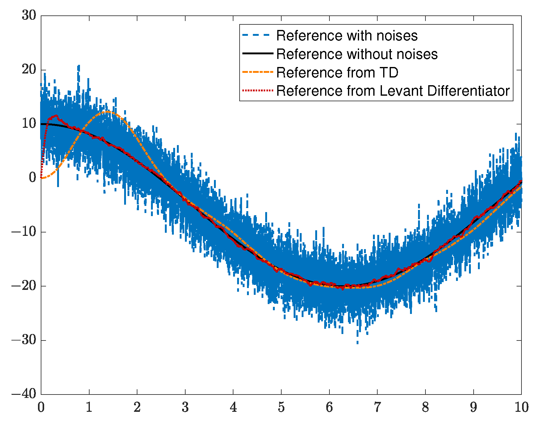
Improving the Tracking Response Speed and Accuracy Compared with TD-based LADRC: The original tracking differentiator (TD) in LADRC has the defects of slow response speed and large overshoot when dealing with fast-changing reference trajectories, which affects the tracking performance of the UAV attitude control. This work replaces the original TD with a Levant differentiator [
23], which has the advantages of finite-time convergence and high noise immunity. Experimental comparisons show that, compared with the TD-based LADRC, the modified LADRC with the Levant differentiator reduces the tracking delay by more than 30% and the overshoot by more than 20%, which effectively improves the tracking response speed and accuracy of the UAV attitude control and makes up for the deficiency of the original TD in fast trajectory tracking.
The structure of this paper is as follows.
Section 2 provides a detailed description of the quadrotor UAV rotor model.
Section 3 introduces the application and establishment of the modified LADRC in a second-order system.
Section 4 analyzes the stability of the designed controller.
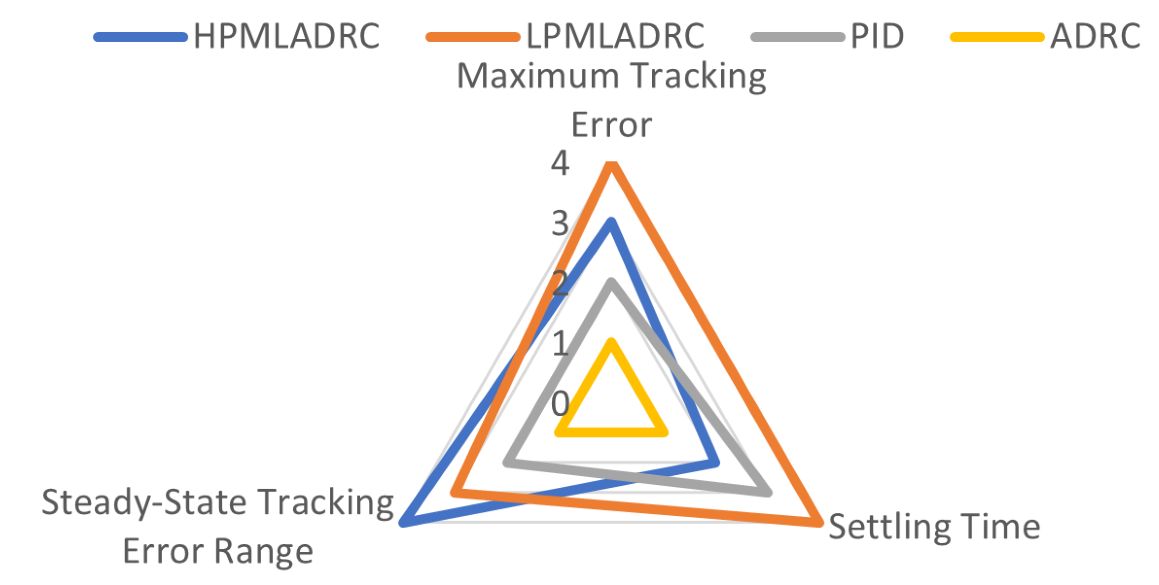
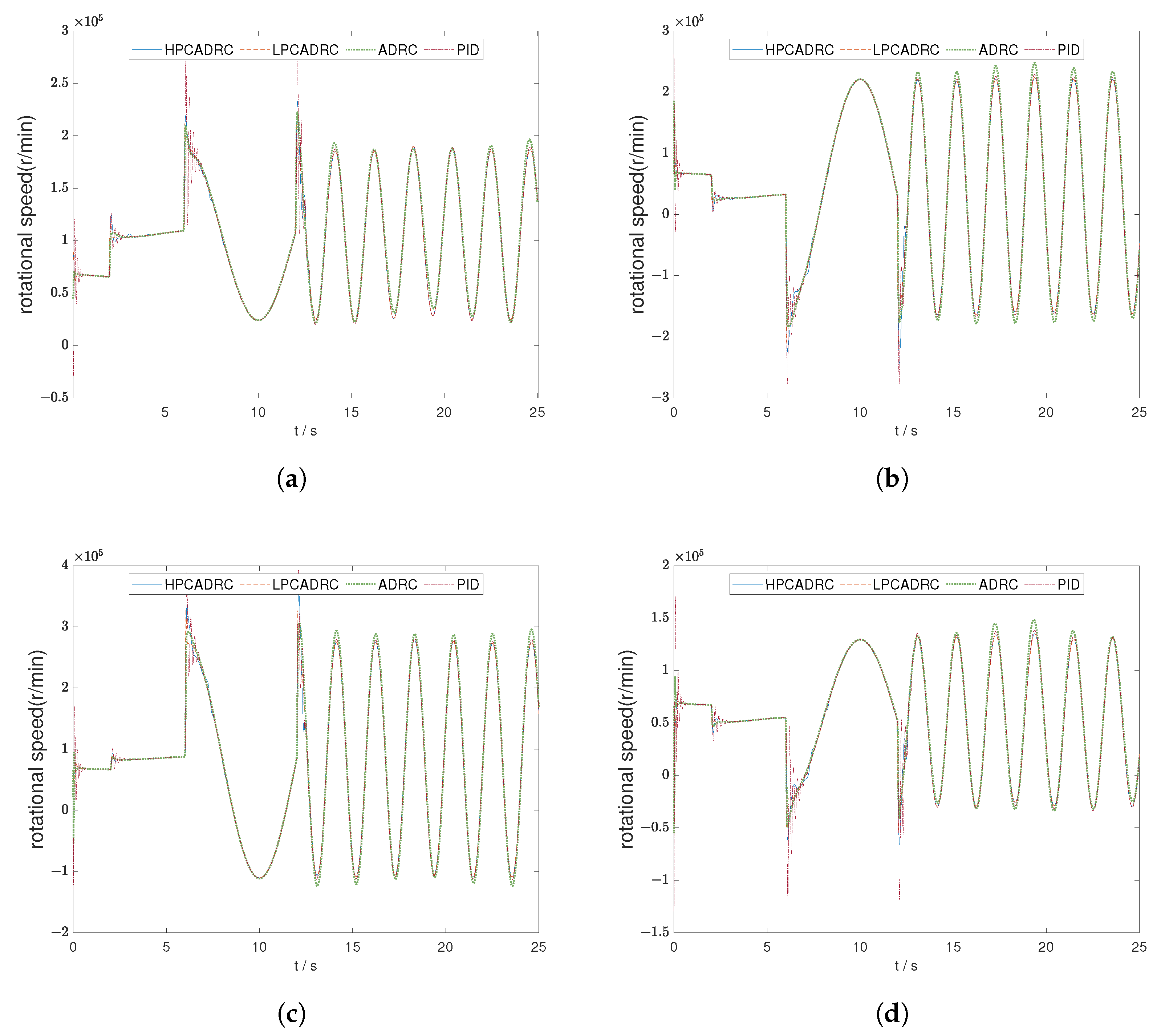
Section 5 compares the disturbance rejection capabilities of PID control, traditional LADRC, and the proposed algorithm through numerical simulations, demonstrating the superiority of the proposed method.
Section 6 summarizes the innovations and main contributions of this paper and outlines directions for future research.
2. Modeling of the UAV
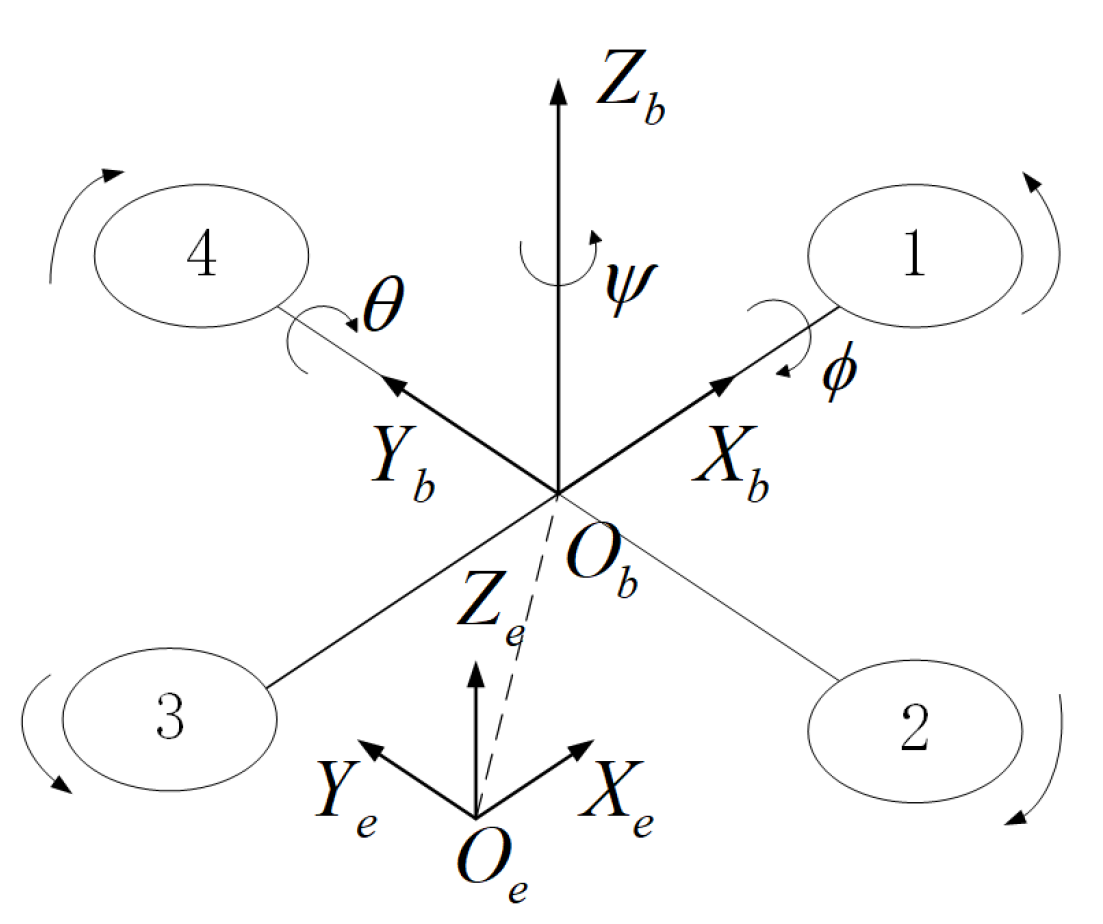
The quadrotor UAV consists of four independently rotating rotors and a cruciform fuselage, with the rotors symmetrically positioned relative to the center of the aircraft, all rotating in the same direction. The quadrotor achieves position and attitude control by adjusting the rotor speeds.
Based on the rotor structure schematic shown in
Figure 1, we define the body-fixed coordinate system
and the inertial coordinate system
to describe the attitude motion of the UAV. Here, the ground coordinate system is denoted as
e, and the body-fixed coordinate system is denoted as
b.
Assume that the quadrotor is a symmetric rigid body and its center of gravity coincides with its geometric center. Let , , , and represent the rotational speeds of the four rotors. The control signals of the quadrotor system are , , , and , where is the total thrust along the axis of the body frame, and , , and are the torques around the , , and axes of the body frame.
The relationships between the control signals (total lift and attitude torques) and the rotor speeds (the actual physical inputs of the quadrotor) are given by the following equations:
where
is the lift coefficient,
b is the counter-torque coefficient, and
l is the distance from each rotor center to the quadrotor’s center of mass. Equation (
1) establishes the input-to-control-signal mapping: rotor speeds
directly determine the total lift
(for vertical motion) and the three attitude torques
(for pitch, roll, and yaw motion, respectively).
To describe how the attitude torques drive the quadrotor’s orientation, the attitude dynamics are derived using Newton–Euler laws:
where
,
,
are the pitch, roll, and yaw angles of the quadrotor;
,
,
are the moments of inertia about the body axes
,
,
;
is the aerodynamic drag coefficient; and
,
,
are the total external disturbance torques around
,
,
. These disturbance torques degrade attitude tracking accuracy, and their time derivatives are defined as follows:
The core objective of the control system is to track the desired attitude commands
,
,
. However, the quadrotor has four rotor speed inputs (
to
) but only three independent attitude torque commands (
,
,
). This creates an underdetermined system in Equation (
1), making it impossible to obtain a unique solution for rotor speeds. To resolve this redundancy, the total lift
is determined by the vertical force balance of the quadrotor, which requires
to counteract gravity:
where
m is the quadrotor mass and
g is gravitational acceleration. Equation (
4) not only uniquely defines
to solve the underdeterminacy in Equation (
1) but also couples vertical stability with attitude control. This coupling, together with the disturbance torques in Equation (
2) and parameter uncertainties (e.g., deviations in
to
), poses significant challenges to control design—challenges that conventional control methods (e.g., PID) struggle to address robustly.
The attitude tracking errors, which quantify the performance of attitude tracking, are defined as follows:
3. Design of the Modified LADRC
To address the aforementioned challenges—including external disturbances, dynamic coupling between attitude angles, and parameter uncertainties—this study adopts and modifies LADRC. LADRC is an advanced control methodology that regulates system behavior by real-time estimation and compensation of total disturbances. In the following subsection, we first elaborate on the fundamental principle of LADRC, with explicit alignment to the quadrotor’s attitude dynamics (Equations (
2) and (
3)), to lay the groundwork for the subsequent modified controller design.
3.1. Principle of LADRC
The principle of LADRC can be demonstrated using a second-order system. The structure of LADRC is illustrated in
Figure 2, which directly corresponds to the individual attitude channels (roll, pitch, yaw) of the quadrotor. Each attitude channel in Equation (
2) follows a second-order dynamic form: for example, the roll channel
matches the standard second-order system framework of LADRC.
In general, the dynamics of a second-order system (representing any single attitude channel of the quadrotor) are described as follows:
where
denotes the total disturbance, which integrates external disturbance torques, system coefficient terms capturing aerodynamic drag and dynamic coupling, and gain deviations;
u represents the control input signal; and
is the nominal control gain.
The total disturbance
in Equation (
5) is explicitly defined to reflect the characteristics of the quadrotor’s attitude dynamics:
where
a denotes the external disturbance torques corresponding to
,
, and
in Equation (
2).
and
are system coefficients responsible for capturing aerodynamic drag and dynamic coupling—for instance,
in the roll channel—and this value reflects the drag term in Equation (
2).
b stands for the actual control gain that incorporates parameter uncertainties, while
accounts for the deviations between the actual control gain and the nominal control gain.
For real-time estimation of
, we assume the total disturbance is differentiable—a valid approximation for most aerial robotics scenarios where disturbances (e.g., wind gusts) evolve smoothly. Let
denote the derivative of the total disturbance; this
h aligns with
,
, and
in Equation (
3), which describe the dynamic evolution of the quadrotor’s disturbance torques. Using this derivative, the second-order system in Equation (
5) is reformulated into an extended state-space model suitable for LADRC observer and controller design:
where the system matrices are defined as follows:
This third-order extended state-space model (Equation (
7)) directly integrates the dynamic characteristics of the quadrotor’s attitude channels (Equations (
2) and (
3)) into the LADRC framework. The extension from the second to third order accommodates the disturbance estimation, ensuring that the subsequent modified LADRC design is tailored to the quadrotor’s specific dynamics. The corresponding linear extended state observer (LESO) is expressed as follows:
where
,
, and
represent the estimated values of the system output
y, its derivative
, and the total disturbance
, respectively. The observer gains
,
, and
are tunable parameters. Using the bandwidth parameterization approach [
24], these gains are configured as follows:
where
denotes the observer bandwidth. The control law is formulated as follows:
where
represents the virtual control law, which is designed for the disturbance-free system after the total disturbance
is compensated by
. Substituting Equation (
5) and assuming
, the system dynamics can be approximated as follows:
It can be observed that after canceling the total disturbance , the system dynamics are approximately transformed into a double-integrator. This fundamental simplification through active disturbance rejection motivates the adoption of the subsequent control structure.
For the resulting second-order system, a Proportional–Derivative (PD) controller augmented with a feedforward term provides a structurally simple, easily implementable, and theoretically sound solution. The virtual control law
is therefore designed as follows:
where
and
represent the controller gains. The terms
and
constitute the PD feedback component, which ensures closed-loop stability and governs the transient performance of the double-integrator system. The inclusion of the reference acceleration
as a feedforward term is essential for enhancing tracking accuracy of time-varying signals, providing the necessary input for ideal tracking under nominal conditions.
Through pole placement techniques, the controller parameters are determined as follows:
where
represents the control bandwidth. Taking the Laplace transform of Equation (
13), the system transfer function is derived as follows:
Since all poles of the transfer function are located in the left half-plane (i.e., they have negative real parts), the system is asymptotically stable, ensuring robust disturbance rejection and improved dynamic response [
25].
3.2. Controller Design
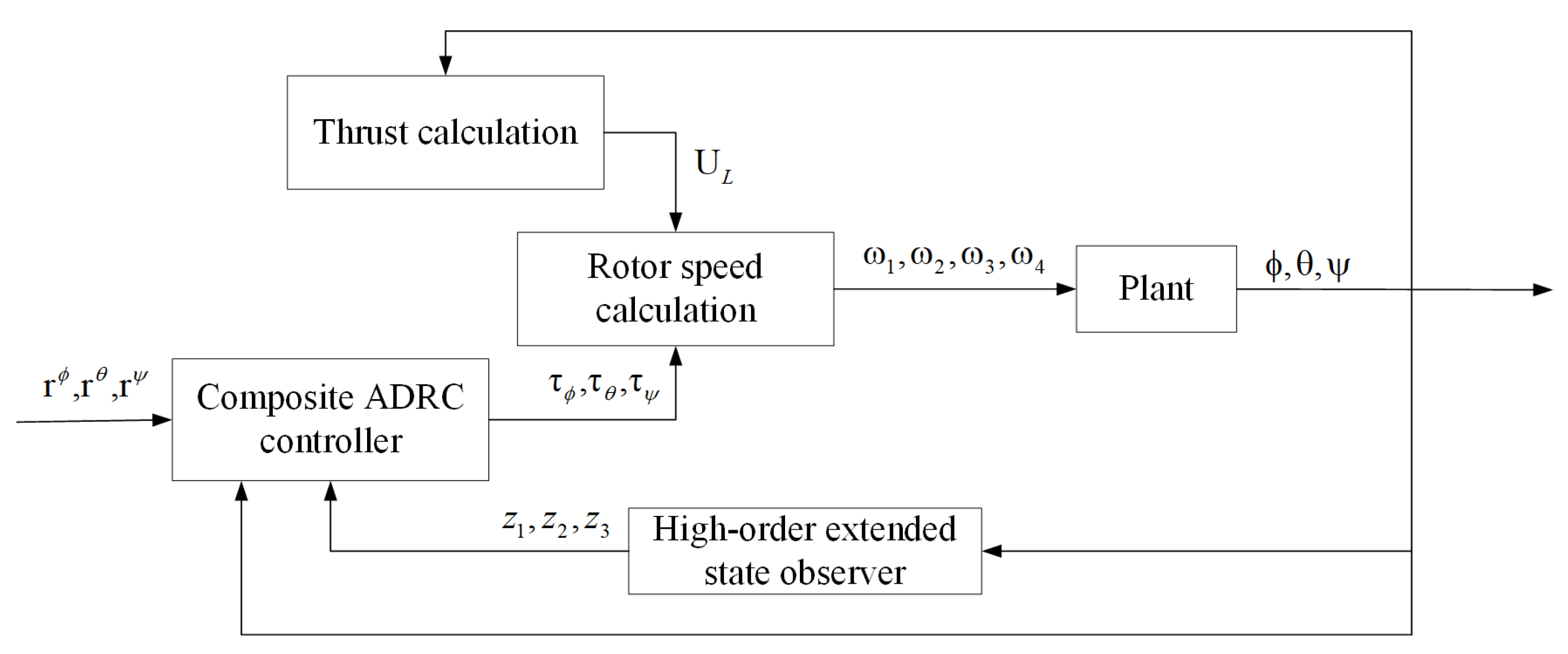
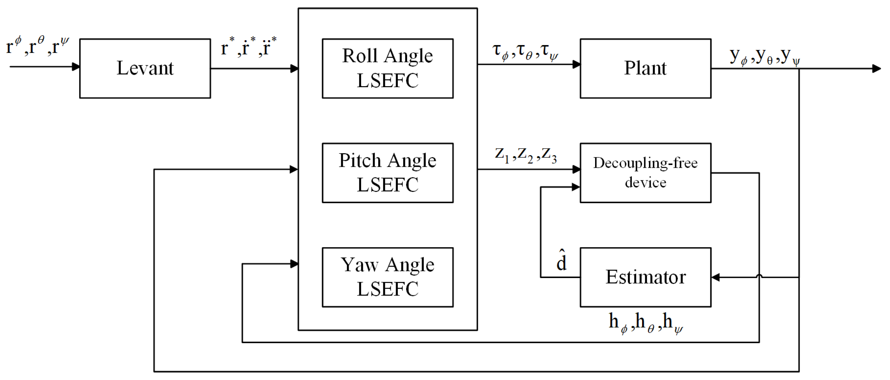
The modified LADRC structure for the quadrotor attitude system is illustrated in
Figure 3. The proposed modified LADRC consists of five main components: the LESO, the Levant differentiator, the Linear State Error Feedback Controller (LSEFC), the decoupling-free device, and the adaptive estimator.
The LESO estimates the system output, its derivative, and the total disturbance. The Levant differentiator provides accurate estimations of the derivatives of the control and system input signals, which are essential for high-performance LADRCs. The LSEFC utilizes the estimated states and disturbances from the LESO to compute the control input, ensuring precise system regulation. The decoupling-free device minimizes interactions between different control channels, thereby enhancing system performance and enabling independent control of each axis. The adaptive estimator dynamically estimates unknown system parameters in real time, allowing the controller to adapt to variations in system dynamics and external disturbances.
The controller design follows a structured approach. First, the controller bandwidth parameters are determined based on the desired system response and dynamic characteristics. Next, the observer bandwidth is selected to ensure accurate derivative estimation of the system output while balancing noise impact and tracking performance. Finally, system parameters are tuned according to the physical properties of the quadrotor to ensure proper control input scaling with respect to the moment of inertia matrix.
By following this design methodology, the final control input formulation is derived, incorporating estimated desired attitude angles and their derivatives, system input, and total disturbances. These estimations are obtained from the LESO, Levant differentiator, and adaptive estimator, providing the necessary information for precise quadrotor attitude control. Given force equilibrium in the vertical direction, the rotor speeds are computed using the torques and thrust generated by the controller, ensuring stable UAV attitude across different flight conditions.
3.2.1. Levant Differentiator
As described in Equation (
13), the total disturbance depends on the derivatives of both the control signal and system input. However, accurate extraction of these derivatives remains a fundamental challenge in control theory and engineering. The Levant differentiator, a type of sliding mode differentiator, has demonstrated superior stability and accuracy in practical applications. The core idea of sliding mode control is to introduce the system error into the sliding mode and adjust the state of the sliding mode so that the system error is quickly converged to zero. The Levant differentiator inherits many advantages of sliding mode control, featuring fewer parameters and a simpler structure. It can ensure the ability to track signals and compute derivatives in a stochastic noise environment and has strong robustness against measurement errors of the signals. The selected Levant differentiator algorithm is as follows:
where
r is the input signal to be differentiated, while
,
,
, and
represent the estimated values of the signal’s zeroth-, first-, second-, and third-order derivatives, respectively. The parameters
,
, and
are tuning coefficients that regulate the differentiator’s performance.
3.2.2. Design of LSEFC
LADRC features three primary tunable parameters: the controller bandwidth
, the observer bandwidth
, and the control gain parameter
. The controller bandwidth
is selected based on the system’s desired settling time, as given by the empirical formula [
26]:
where
N is the system order and
denotes the time required for the system response to reach and remain within 98% of its final value. To ensure effective feedback control, the observer bandwidth
must exceed the closed-loop bandwidth
. This relationship is represented by the observer bandwidth scaling factor
, defined as follows:
According to empirical tuning guidelines, the observer bandwidth should typically range from three to ten times the control bandwidth. Considering noise sensitivity and tracking accuracy, this study sets .
The control gain parameter is determined based on the system’s moment of inertia matrix. Specifically, for the roll(), pitch(), and yaw() controllers, the respective values are given by , , and , where , , and represent the moments of inertia along each axis. Proper selection of ensures that the control input aligns with the physical system characteristics, thereby enhancing control performance.
The final control input expressions are given as follows:
where
represent the estimated attitude angles and their derivatives, while
denotes the LESO estimates of system inputs and disturbances. The overall modified LADRC structure is depicted in
Figure 4.
3.2.3. Decoupling-Free Device
The LESO employs three input quantities—namely, the control inputs
,
, and
—along with the system output
y and the derivative of the total disturbance
h. Correspondingly, it provides three output quantities: the estimate of the system output
, the estimate of its derivative
, and the estimate of the total disturbance
. The system dynamics, as described in Equation (
2), are updated according to Equations (
5) and (
9):
The specific expressions for the disturbance input terms
(
) are given as follows:
where
,
,
.
Substituting Equation (
20) into Equation (
21), we obtain
3.2.4. Adaptive Estimator Design
In parameter estimation, a commonly employed model follows a linear parameterization structure:
where
is the system output,
d is the vector of unknown parameters to be estimated, and
represents the known signal matrix obtained from system measurements. Thus, only the parameter
d remains unknown in Equation (
23).
To predict the system output based on parameter estimation, we define
where
denotes the predicted output. The prediction error is given by
In the standard least-squares method, parameter estimation is achieved by minimizing the total prediction error:
To introduce exponential forgetting of past data, Equation (
26) is modified as follows:
where
is a time-varying forgetting factor. The parameter update rule is as follows:
Meanwhile, the gain update rule is formulated as follows:
A more efficient implementation modifies this to
To adapt the forgetting factor to the signal excitation level, it is adjusted based on the norm of
P:
where
and
are positive constants representing the maximum forgetting rate and the preset boundary of
P, respectively.
This study proposes two parameter estimation approaches, with their core design logic referencing the parameter estimation framework [
27]. Both methods employ recursive least squares with exponential forgetting for real-time disturbance estimation, without utilizing Fourier transform analysis. The first is Low-Precision Modified Linear Active Disturbance Rejection Control (LPMLADRC), which utilizes both real-time angle and angular velocity measurements for disturbance estimation. This approach provides balanced performance with moderate computational requirements.
The second approach, High-Precision Modified Linear Active Disturbance Rejection Control (HPMLADRC), achieves enhanced estimation accuracy by exclusively using real-time angle measurements to estimate both the frequency and amplitude of unknown disturbances. The implementation builds upon the previously described exponential forgetting least squares framework, with the following specialized application:
Disturbance Parameter Estimation—For HPMLADRC, the regressor vector is constructed exclusively from real-time angle measurements to estimate disturbance frequency and amplitude . For LPMLADRC, incorporates both angle and angular velocity measurements for generalized disturbance estimation.
Real-time Compensation—The estimated disturbance parameters are continuously integrated into the control framework. The total disturbance estimate
is enhanced with the estimated disturbance model:
The fundamental distinction between LPMLADRC and HPMLADRC lies in their measurement utilization: LPMLADRC employs both angle and angular velocity data for robust disturbance estimation, while HPMLADRC exclusively uses angle measurements to achieve higher precision in estimating disturbance frequency and amplitude characteristics.
3.3. Rotor Speed Calculation
The rotor speeds
,
,
, and
are determined by solving the control input equation:
In this context, the total thrust
is derived from the vertical force balance equation, as referenced in Equation (
4).
Furthermore,
can be expressed as follows:
This expression for
ensures that the vertical forces are balanced, allowing the quadrotor to hover or maintain a desired altitude.


