Abstract
This paper proposes a 2D semi-analytical model based on the subdomain method for the performance analysis of a brushless doubly fed reluctance machine (BDFRM) with a salient pole rotor. In particular, assuming an infinite magnetic permeability of the iron core and assuming a smooth stator, the field calculation region is divided into two solution subdomains, i.e., the rotor slot and air-gap. The magnetic vector potential in each subdomain is obtained by solving the governing PDE by the separation of variables method and employing the boundary conditions between adjacent interfaces. Moreover, based on the stored magnetic energy in the air-gap, the calculation of the three-phase windings’ self and mutual inductances is presented. Through a case study involving a 6/2 pole BDFRM, the accuracy of the developed subdomain model is confirmed by comparing its analytically predicted results with those obtained from two-dimensional finite element method (FEM) simulations.
1. Introduction
Brushless doubly fed reluctance machine (BDFRM) has been extensively investigated over the past few years, and several research studies have been conducted in the field of BDFRM operation [1]. Particularly, it allows the use of a partially rated inverter in many variable-speed applications. The machine incorporates a uniquely designed rotor alongside a stator equipped with two distinct windings, each characterized by a different number of poles. The stator assembly comprises conventional laminated steel and two separate stationary winding sets. Magnetic coupling between these stator winding sets is facilitated by the rotor’s inherent ferromagnetic saliency, making the rotor geometry a critical factor in determining the degree of mutual magnetic interaction [2]. This BDFRM maintains the economic benefits associated with Doubly Fed Induction Generators by enabling the employment of a power converter sized at approximately 30% of the machine’s rated capacity. Moreover, the BDFRM offers the advantage of brushless construction, eliminating the need for maintenance-related brush components [3].
The two sets of stator windings, i.e., -pole power and -pole control windings, have their own independent three-phase connection. The power winding is grid-connected, and the control winding may be fed from a bi-directional converter [4].
If the control winding is supplied with a power converter, the doubly-fed adjustable-speed mode of the BDFRM can be achieved through appropriate control strategies [5]. The basic condition for electromechanical energy conversion for this machine is that the reluctance rotor must satisfy the following condition [6]:
where is the number of rotor poles; and are the power and control winding pole pairs, respectively. Only the positive sign case in Equation (1) will be considered in this study. Thus, the machine steady-state doubly fed synchronous speed is as follows [6]:
where (in rad/s) is the angular speed; the indexes and refer, respectively, to the power and control windings; is related to the rotor.
Detailed knowledge of the magnetic field distribution in electrical machines is essential for the design and analysis of their performance prior to the manufacturing process. Moreover, the precise knowledge of parameters is of critical importance for correct performance prediction and design optimization.
Numerical techniques enable very accurate prediction of the machine’s electromagnetic performances. However, the numerical approach requires a longer computational time for analyzing the characteristics of the machines. On the other hand, analytical methods can provide accurate solutions with less computational effort. In fact, analytical calculations have the advantages of being flexible for initial performance evaluation and optimization of electrical machines.
A technique using the concept of winding functions has been utilized for developing inductance expressions of the BDFRM [7]. In [8], the transient model of the BDFRM is presented by using the winding function principles in order to evaluate the BDFRM model for different modes of operation. Reference [9] introduces an analytical approach for the analysis and design of a brushless doubly fed reluctance generator, which combines both equivalent electrical and magnetic circuit representations. Additionally, a semi-analytical framework incorporating an equivalent electric circuit alongside a Reluctance Network Model for the purpose of size optimization in novel BDFRM designs is presented in [10]. The validity and effectiveness of this modeling approach have been substantiated through comprehensive experimental testing on prototype machines.
Subdomain modeling is a rigorous analytical technique that entails partitioning the electromagnetic problem into distinct physical regions, or subdomains, within which Maxwell’s equations are solved analytically [11]. Utilizing this approach with the incorporation of hyperbolic functions, the magnetic vector potential distribution has been computed for surface-mounted permanent magnet (PM) machines as demonstrated in [12], and for PM machines featuring surface-inset magnets with an outer rotor configuration, as detailed in [13]. In these analyses, magnetic saturation effects were not considered. Furthermore, an exact two-dimensional subdomain method tailored for switched reluctance machines fed by sinusoidal current inputs is developed in [14].
In this study, the subdomain method is employed to analytically determine both the magnetic field distribution and inductance characteristics of a brushless doubly fed reluctance machine featuring a smooth stator and salient pole rotor. The organization of the paper is as follows: first, the development of the two-dimensional subdomain model for the investigated machine is described; next, the derivation of key parameters—including the flux density components, electromagnetic torque, and inductances—is detailed. Subsequently, the analytical findings from a case study are presented and validated through comparison with results obtained via numerical simulation. The study concludes with a summary of the main outcomes.
2. Motor Geometry and Assumptions
The basic configuration of the BDFRM considered for this work is represented in Figure 1. The machine has a smooth stator and a simple salient laminated rotor with saliencies. The geometrical parameters are the inner and outer radii of the rotor, the inner radius of the stator, and the rotor slot opening.
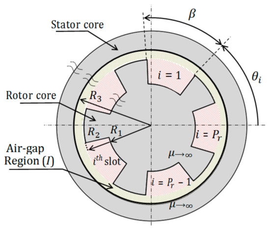
Figure 1.
Geometry of a BDFRM with a smooth stator and rotor saliencies.
The slot opening angle is . The angular position of the rotor slot is defined as
where is the angular position of the rotor and is the number of rotor poles.
As shown in Figure 1, this machine has been partitioned into two regions: Region for the air-gap and Region for the rotor slots.
The model is formulated in magnetic vector potential in 2D polar coordinates with the following main assumptions:
- The stator and rotor cores are assumed to be infinitely permeable, with the stator core considered slotless.
- A two-dimensional magnetic vector potential formulation is adopted, and end effects are neglected (infinitely long machine).
- Eddy-current effects within the materials are neglected.
- The rotor operates at constant angular velocity,
- Both stator windings are supplied by balanced sinusoidal currents, each represented by an equivalent current sheet.
The results obtained from the proposed model are valid under the stated simplifying assumptions, which provide an approximate analytical framework. They are appropriate for qualitative analysis and initial design exploration, quick estimations, or long laminated machines. For advanced design, each assumption must be revisited to correct or refine the predictions.
3. Magnetic Field Calculation
According to the 2D problem assumption, the magnetic vector potential only has one component along the -direction and only depends on and coordinates. As mentioned previously, the entire domain of the magnetic field is divided into two subdomains, so that, in polar coordinates, in the air-gap (Region ) and in the rotor slot (Region ), with being the unit vector along the -axis.
For the sake of clarity and simplicity of the general solutions in the different subdomains, the following notations are defined as follows:
3.1. Equivalent Current Sheet Distribution
The stator windings are considered as an equivalent current sheet distributed over the stator inner radius for simpler analysis. In addition, the surface current density is limited to the fundamental term. Therefore, in the presence of an infinitely permeable stator iron, the expressions, with respect to time, of the sinusoidal current densities and , corresponding to the power and control winding currents, respectively, are
Here, denotes the angular position along the stator core. The parameters and are the phase shifts with respect to an arbitrary reference of each winding (phase- axis of the power and control winding, respectively). The variables and indicate the angular frequencies of the electrical supplies to the two stator windings. The amplitudes of the current densities in the power and control windings are denoted by and , respectively, and are determined as described in [15]:
where is the number of series turns per phase, is the three-phase stator current amplitude, and is the fundamental winding factor of the power (or control) winding. is the inner stator radius.
The resultant current sheet acting along the stator interior surface is the superposition of the two current densities produced by the power and control windings, such as
If the rotor rotates with a constant angular velocity given by Equation (2), the current sheet expression (Equation (9)) can be transformed from the stator reference frame to the rotor reference frame (angle ) using Equation (10), and the result is given by Equation (11):
Reference [16] presents an analysis to identify the field characteristics and discusses their impact on the analysis and design of the brushless doubly fed induction machine, which has similar stator doubly fed windings. The characteristics are determined from an analysis of the sum of two rotating sinusoidal field waveforms with different angular frequencies and pole pairs. It is concluded that the form of the field distribution depends on the relative amplitude of the two field components, excitation frequencies, and their relative angular offset. In this particular case, the stator windings meet the following condition related to the angular frequencies and pole pairs:
The spatial profile of the magnetic field remains invariant over time and rotates synchronously with the machine, given that the angular velocities of the two underlying flux density distributions are identical. However, the instantaneous angular position and the respective peak (positive and negative) values of the resultant flux density are governed by the relative angular displacement between the two component flux distributions. This relative offset is fundamentally determined by the machine’s operating conditions [16]. Consequently, when the condition expressed in Equation (12) is satisfied, the rotor achieves synchronous rotation with respect to the resultant stator surface current density, as specified in Equation (13):
Under these conditions, the electromagnetic field problem is reduced to a magnetostatic analysis. The subsequent study will be confined to this specific synchronous operating regime. As a result, the expression describing the current density, as observed from the rotor reference frame (cf. Equation (11)), is given by:
It should be noted that, in real operation, the synchronization condition (Equation (12)) is often not exactly satisfied. When a small slip exists—either in steady asynchronous regimes or during transients—the electromagnetic model must include time-dependent terms. In this case, the equivalent current sheet no longer appears as a constant distribution but instead carries frequency components shifted by the slip frequency. This leads to fields that vary in both space and time, and to additional induced currents in the conductors. Although such an extension increases the complexity of the formulation, it allows the model to capture essential physical effects such as torque oscillations, additional losses, and dynamic interactions between the stator and rotor.
3.2. General Solution of Laplace’s Equation in Rotor Slots (Region i)
The field behavior in the rotor slot is governed by the following Laplace’s equation:
The tangential component of the magnetic field at both the sides and the base of each rotor slot vanishes, reflecting the idealization of an infinitely permeable iron core. In addition to the continuity condition enforced at the interface between the slot and the air-gap regions, the slot subdomain (refer to Figure 2) is thus subject to the following boundary conditions:

Figure 2.
slot subdomain with its boundary conditions.
Considering the Neumann boundary condition described in Equation (17), the solution can be sought in the form detailed in references [17,18,19]:
By using the boundary conditions at the bottom of the rotor slot from Equation (18) and the continuity condition at the top of the slot from Equation (16), the solution for in Equation (19) can be simplified to Equation (20):
where is a positive integer and is defined by Equation (4).
The constant terms and are coefficients to be determined. For this purpose, condition (16) is considered. The air-gap magnetic vector potential is expanded into a Fourier series over the rotor slot opening at =. It is obtained for the mean value as
and for the harmonic, we can write the following:
The expression for the coefficient is given in Appendix A.
3.3. General Solution of Laplace’s Equation in Air-Gap (Region I)
The Laplace’s equation governing the field in the air-gap subdomain, which is an annular domain delimited by the external radius of the rotor and the stator internal radius , is given by:
where is the magnetic vector potential in the air-gap region.
The air-gap subdomain and the associated boundary conditions are shown in Figure 3.
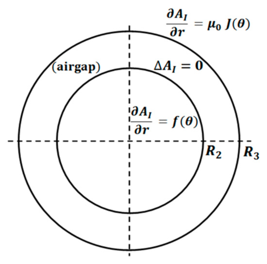
Figure 3.
Air-gap subdomain (region ) with its boundary conditions.
In the case of an ideal stator iron core with infinite magnetic permeability, the boundary condition at the interface between the air-gap and the current sheet can be expressed as follows:
where is the magnetic permeability of free space.
Following the formulation of [17,18], the function is introduced as
where is the magnetic vector potential in the -rotor slot region, which is given by Equation (20).
The boundary condition at is
The general solution of Equation (23) can be found by separating the variables and . By taking into account the boundary conditions in Equations (24) and (26), the solution can be written as [17,18]:
where is a positive integer, and are defined by Equations (4) and (5). The Fourier coefficients , , , and are determined using a Fourier series expansion of and Equation (25) over the air-gap interval, such as
where
: it is the boundary function defined at the slot upper surface, representing the spatial distribution of the magnetic potential along the angular coordinate.
, : , and are the Fourier coefficients of the magnetic potential in the air-gap region, which is used to describe the circumferential field distribution.
, : and are the Fourier coefficients in the slot-opening region, ensuring the continuity of the potential and field at the slot boundaries.
The expressions of these coefficients are given in Appendix A.
3.4. Magnetic Flux Density and Torque Calculation
Knowing the solutions of the vector potential in the air-gap domain, the radial and tangential components of the magnetic flux density and are, respectively, determined according to Equations (32) and (33):
Rearranging Equations (32) and (33), the components of the flux density distribution in the air-gap domain can also be expressed through Equations (34) and (35):
Radial and tangential components of air-gap magnetic fields are employed to find the electromagnetic torque using the Maxwell stress tensor method. To evaluate the electromagnetic torque in two-dimensional cylindrical geometries, the integration path is chosen as a circular contour enclosing the rotor within the air-gap. The torque is then expressed by integrating the Maxwell stress tensor over this path, represented as follows:
where is the mid-air-gap radius of the circle taken as the integration path, and is the machine axial length.
By substituting the expressions given in Equations (34) and (35) into Equation (36), the resulting analytical formula for the electromagnetic torque takes the following form:
with
3.5. Windings Self and Mutual Inductances
Three-phase self-inductances , and mutual inductance between the two sets of primary and secondary windings , can be calculated from the magnetic energy [20] as
where , and are, respectively, the magnetic energies when only the power winding, the control winding, and both windings are fed with their respective three-phase currents .
For a linear material, the magnetostatic energy contained in a field in a volume can be expressed in terms of the magnetic vector potential and the current density as
In the case of a surface current distribution, the expression of reduces to
where is the axial length of the machine, is the magnetic permeability of free space, is the normal unit vector, and is an elementary curvilinear displacement.
At , the elementary linear element is
To evaluate the magnetic energy due to the stator current sheets, Equations (42) and (43) are used. The integration path is chosen as a circular contour, with varying from 0 to , defined on the inner radius of the stator and therefore encompassing all the poles enclosing the rotor.
4. Analytical Results and Comparison with Finite Element Analysis
As a case study, a BDFRM having a two-pole power winding, a six-pole control winding, and a simple salient rotor composed of four saliencies is investigated under unsaturated conditions. The air-gap flux density, the static torque, and the three-phase inductances are calculated on the basis of the proposed model and verified by a two-dimensional FE model using “Femm version 4.2” software [21].
The main design parameters of the investigated machine are shown in Table 1. The analytical solutions in the domains of the air-gap (of harmonic order ) and in the rotor slots (of harmonic order ) have been computed with a finite number of harmonic terms and , respectively. Using values of , the field solution is predicted with good accuracy.

Table 1.
Main parameters of the studied machine.
The 2D FEM model is created on the basis of the geometric parameters given in Table 1. As the sketch in Figure 4 highlights, the rotor has four salient poles, and the stator is represented by a circle of radius . Moreover, the entire cross-section of the machine is modeled.

Figure 4.
Model for finite element validation of the studied 6/2 BDFRM. Zoomed view of a detail showing arc segments spread over the stator bore.
A circular boundary representing the inner radius of the stator is established. This boundary is discretized into multiple circular arcs, each subjected to a Neumann boundary condition to enforce the tangential component of the magnetic field. This segmentation into circular arcs is performed with an angle of 1°, which is an optimal value that ensures an accurate representation of the current density distribution, which is intended to replicate the analytical model’s prescribed conditions, specifically, the superposition of two sinusoidal current densities with distinct amplitudes and pole pair numbers. Furthermore, a reference frame aligned with the stator is defined. The reference axis is chosen consistently with that used in the analytical formulation, for the phase shifts and . In addition, the relative permeability of the iron core in the FE model is set equal to , which is a large value that is used to simulate infinite permeability.
4.1. Magnetic Vector Potential, Flux Density, and Torque Calculations
The predicted magnetic vector potential variation in the middle of the air-gap is shown in Figure 5 for two rotor initial positions. The comparison shows that there is a good agreement between the FEA results and those predicted using the analytical model.
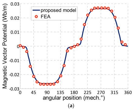
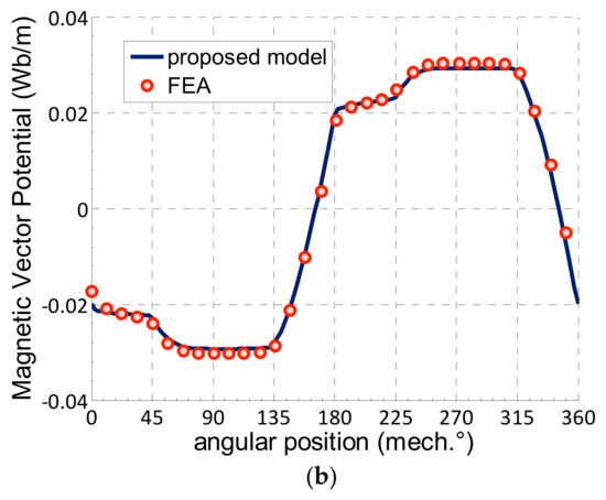
Figure 5.
Magnetic vector potential in the middle of the air-gap for the 2/6-pole machine: Peak value of current density of power winding: /m; Peak value of current density of control winding: : (a) , (b) .
In addition, the flux density distributions in the whole air-gap region are analyzed and compared. As illustrated in Figure 6, the radial and tangential flux density waveforms at the mid air-gap, obtained from both FEA and the analytical approach, are in very good agreement, further demonstrating the high accuracy of the proposed analytical model.
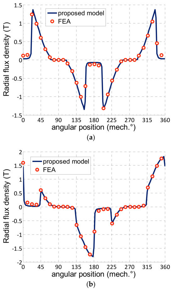
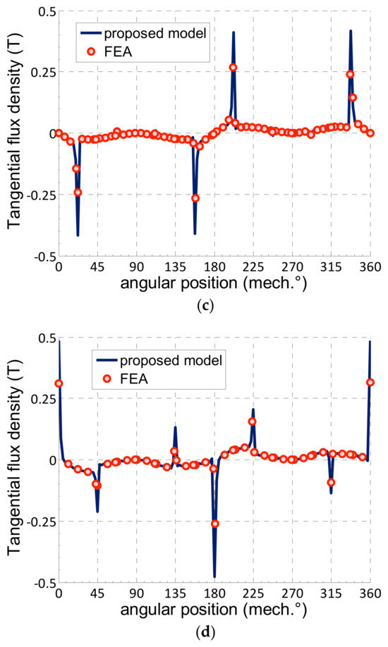
Figure 6.
Flux density in the middle of the air-gap for the 2/6-pole machine: Peak value of current density of power winding: /m; Peak value of current density of control winding: : (a) Radial flux density component, .
(b) Radial flux density component, .
(c) Tangential flux density component,
. (d) Tangential flux density component,
.
In a brushless doubly fed machine (BDFM), the power winding is typically connected directly to the power grid, while the control winding is connected through a power electronic converter. Torque control is achieved by adjusting the magnitude and angle of the control winding’s current. Thus, in the present analysis, torque is computed by maintaining the phase shift of the power winding to zero, while the machine can be controlled by varying the control winding current angle for a given current sheet amplitude of the respective winding. For two sets of windings current densities, Figure 7 shows the torque waveform as a function of the control winding current angle. In both cases, it can be seen that the analytical results show good agreement with the FEA results.
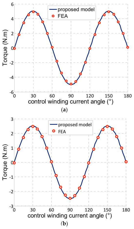
Figure 7.
Static torque versus control winding current angle for the 2/6-poles machine: (a) Peak value of current density of power winding: /m; Peak value of current density of control winding: . (b) /m; .
Table 2 presents the relative error in the maximum developed torque obtained from finite element simulations for different permeabilities and magnetic materials. The data show that for relative permeabilities around 5000, the relative error remains within acceptable limits for predicting machine performance. However, the error increases significantly when the magnetic material experiences saturation. Additionally, it is observed that the critical control angle at which the pull-out torque occurs is slightly higher than the theoretical value of 30°, as predicted by the analytical model.
Table 2.
Relative error of maximum torque evaluation from finite element analysis for different magnetic materials. Rotor inner radius:
25 mm; ; rotor slot opening: ; air-gap length: 1 mm; /m; Peak value of current density of control winding: .
4.2. Inductance Calculation
The three-phase self-inductances are obtained from the total energy associated with only the imposed current sheet with respect to the considered winding, while the mutual-inductance between the two windings is obtained similarly by superimposing the current sheets of the two windings.
The magnetic energy is analytically evaluated using the energy relationship given in Equation (44). For the finite element analysis (FEA), the built-in magnetic energy calculation feature within the “femm” software post-processor is utilized to obtain the corresponding values.
The inductance values are expressed in per unit (p.u.), as they are derived from magnetic energy calculations. Specifically, the different values of electromagnetic energy have been normalized by dividing them by the maximum magnetic energy obtained from a reference machine. This reference pertains to a machine with an identical stator current sheet and air-gap, but fitted with a cylindrical rotor. Both analytically derived and finite element analysis (FEA) model results have been normalized in this manner, ensuring a consistent basis for comparison across models.
Figure 8 shows the evolution of self and mutual inductances, as a function of control winding current angle, obtained by analytical model and finite element simulations. In Figure 8b, it can be seen that the variation in the mutual inductance expresses the reluctance nature of the BDFRM.
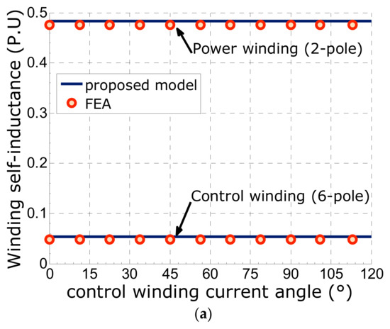
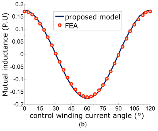
Figure 8.
Three-phase winding inductances versus control winding current angle for the 2/6-pole machine: (a) Three-phase self-inductances, (b) Mutual inductance.
4.3. Design Parameters Sensitivity
The analytical model is employed to evaluate the sensitivity of torque performance to key geometric parameters, namely the rotor pole arc-to-pole pitch ratio, the air-gap length, and the rotor inner-to-outer radius ratio. The obtained results are presented in Figure 9. It can be seen from Figure 9a that, like the synchronous reluctance machine equipped with a simple salient rotor, the rotor pole arc angle, in the studied machine, is one of the most influential design parameters (Figure 9a). On the other hand, it is noticed in Figure 9b that rotor slot depth is a less influential design parameter.
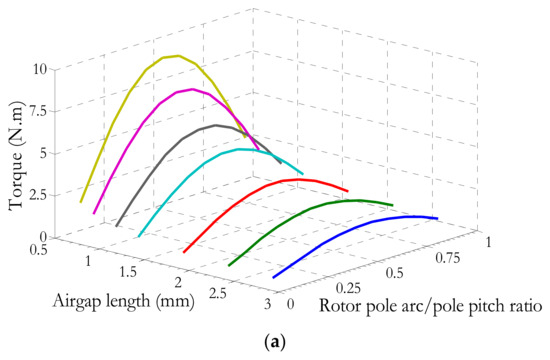
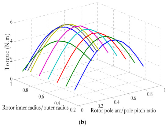
Figure 9.
Developed torque as a function of rotor pole arc/pole pitch ratio in different scenarios: (a) Air-gap lengths, (b) Rotor inner radius/outer radius, with air-gap length of 1 mm. Peak value of the current density of the power winding /m; Peak value of current density of control winding: ,
,
.
5. Conclusions
A 2D analytical magnetic model is presented for the brushless doubly fed reluctance machine (BDFRM) with a salient-pole rotor. The model employs a Fourier analysis based on the subdomain method to derive explicit expressions for the magnetic vector potential, air-gap flux density, electromagnetic torque, and three-phase winding inductances. In this study, the model is applied to a four-pole rotor machine, and its accuracy is validated through finite element analysis. Key contributions include the modification of boundary conditions, the introduction of subdomains for more precise flux computation, and the analytical treatment of winding slot harmonics. The proposed model enables rapid evaluation of the machine’s performance for different stator winding pole combinations. Future work will extend the model to account for stator slotting effects, improving the prediction of torque characteristics and supporting the machine’s design optimization.
Author Contributions
Conceptualization, S.T., C.G., and S.M.; methodology, S.T., C.G., and S.M.; software, S.T. and C.G.; validation, S.T., C.G., S.M., R.I., and N.T.; writing—original draft preparation, S.T. and C.G.; writing—review and editing, S.T., C.G., S.M., N.T., and R.I.; supervision, N.T. and R.I. All authors have read and agreed to the published version of the manuscript.
Funding
This research received no external funding.
Data Availability Statement
The original contributions presented in this study are included in the article. Further inquiries can be directed to the corresponding author(s).
Conflicts of Interest
The authors declare no conflict of interest.
List of Symbols
| Symbol | Definition |
| Magnetic vector potential (Wb/m) | |
| , | Radial, tangential flux density component(T) |
| Three-phase stator current amplitude (A) | |
| , | Current density of the power winding, control winding (A/m) |
| , | Peak value of the current density of the power winding, control winding (A/m) |
| Fundamental winding factor of the power (or control) winding | |
| Machine axial length (m) | |
| , | Self-inductance of the power winding, control winding (H) |
| Mutual inductance between the windings (H) | |
| Number of series turns per phase for the power winding, control winding | |
| , | Power winding, control windings, and pole pair number |
| Number of rotor poles | |
| Inner rotor radius (m) | |
| Outer rotor radius (m) | |
| Inner stator radius (m) | |
| Mid-air-gap radius (m) | |
| , | Phase shift with respect to an arbitrary reference of the power winding, the control winding (rad) |
| Rotor slot opening angle (rad) | |
| Angular position of the rotor slot | |
| Electromagnetic torque (N·m) | |
| Rotor angular speed (rad/s) |
Appendix A
Integrals frequently encountered in this section can be denoted as follows:
for ,
for ,
Expressions of the coefficients , , , and for the air-gap domain:
The development of Equations (29) and (31) leads to the following expressions, establishing the relationship between the harmonic rank and the winding pole pairs and : for :
for :
for and :
for :
for :
for and :
The coefficient defined in Equations (28) and (30) can be written as follows:
where is the number of rotor slots.
Further manipulation of Equations (A13) and (A14) yields the subsequent forms expressed in Equations (A15) and (A16), respectively.
Expression of the coefficient for the rotor slot domain:
Solving Equation (22) produces a linear relationship linking the coefficient with the coefficients … , , , :
A system of ( linear equations with the same number of unknowns can be solved by rewriting the above equations in matrix and vector format.
References
- Sadeghian, O.; Tohidi, S.; Mohammadi-Ivatloo, B.; Mohammadi, F. A Comprehensive Review on Brushless Doubly-Fed Reluctance Machine. Sustainability 2021, 13, 842. [Google Scholar] [CrossRef]
- Xu, L.; Wang, F. Comparative study of magnetic coupling for a doubly fed brushless machine with reluctance and cage rotors. In Proceedings of the 1997 IEEE Industry Applications Conference Thirty-Second IAS Annual Meeting, New Orleans, LA, USA, 5–9 October 1997; Volume 1, pp. 326–332. [Google Scholar] [CrossRef]
- Dorrell, D.G.; Knight, A.M.; Betz, R.E. Improvements in Brushless Doubly Fed Reluctance Generators Using High-Flux-Density Steels and Selection of the Correct Pole Numbers. IEEE Trans. Magn. 2011, 47, 4092–4095. [Google Scholar] [CrossRef]
- Chaal, H.; Jovanovic, M. Direct power control of brushless doubly-fed reluctance machines. In Proceedings of the 5th IET International Conference on Power Electronics, Machines and Drives, Brighton, UK, 19–21 April 2010; pp. 1–6. [Google Scholar]
- Wang, F.; Zhang, F.; Xu, L. Parameter and performance comparison of doubly fed brushless machine with cage and reluctance rotors. IEEE Trans. Ind. Appl. 2002, 38, 1237–1243. [Google Scholar] [CrossRef]
- Han, P.; Zhang, J.; Cheng, M. Analytical Analysis and Performance Characterization of Brushless Doubly Fed Machines with Multibarrier Rotors. IEEE Trans. Ind. Appl. 2019, 55, 5758–5767. [Google Scholar] [CrossRef]
- Betz, R.E.; Jovanovic, M.G. Introduction to Brushless Doubly Fed Reluctance Machines—The Basic Equations; Aalborg University: Aalborg, Denmark, 1998. [Google Scholar]
- Ibrahim, A.K.; Marei, M.I.; El-Goharey, H.S. Transient Model of Brushless Doubly Fed Reluctance Machine using ABC Reference Frame. Int. J. Recent Trends Eng. Res. 2018, 4, 26–32. [Google Scholar] [CrossRef]
- Hsieh, M.F.; Lin, I.H.; Dorrell, D.G. An analytical method combining equivalent circuit and magnetic circuit for BDFRG. IEEE Trans. Magn. 2014, 50, 1–5. [Google Scholar] [CrossRef]
- Staudt, T.; Wurtz, F.; Gerbaud, L.; Batistela, N.J.; Kuo-Peng, P. An optimization-oriented sizing model for brushless doubly fed reluctance machines: Development and experimental validation. Electr. Power Syst. Res. 2016, 132, 125–131. [Google Scholar] [CrossRef]
- Dalal, A.; Nekkalapu, S.; Kumar, P. 2-D Analytical Subdomain Model for Hybrid Dual-Rotor Motor. IEEE Trans. Magn. 2016, 52, 1–9. [Google Scholar] [CrossRef]
- Jabbari, A. An Analytical Expression for Magnet Shape Optimization in Surface-Mounted Permanent Magnet Machines. Math. Comput. Appl. 2018, 23, 57. [Google Scholar] [CrossRef]
- Vahaj, A.; Rahideh, A.; Moayed-Jahromi, H.; Ghaffari, A. Exact Two-Dimensional Analytical Calculations for Magnetic Field, Electromagnetic Torque, UMF, Back-EMF, and Inductance of Outer Rotor Surface Inset Permanent Magnet Machines. Math. Comput. Appl. 2019, 24, 24. [Google Scholar] [CrossRef]
- Ben Yahia, M.; Boughrara, K.; Dubas, F.; Roubache, L.; Ibtiouen, R. Two-Dimensional Exact Subdomain Technique of Switched Reluctance Machines with Sinusoidal Current Excitation. Math. Comput. Appl. 2018, 23, 59. [Google Scholar] [CrossRef]
- Lubin, T.; Mezani, S.; Rezzoug, A. Analytic calculation of eddy currents in the slots of electrical machines: Application to cage rotor induction motors. IEEE Tran. Magn. 2011, 47, 4650–4659. [Google Scholar] [CrossRef]
- Mathekga, M.E.; Ademi, S.; McMahon, R.A. Brushless Doubly Fed Machine Magnetic Field Distribution Characteristics and their Impact on the Analysis and Design. IEEE Trans. Energy Convers. 2019, 34, 2180–2188. [Google Scholar] [CrossRef]
- Lubin, T.; Mezani, S.; Rezzoug, A. Exact Analytical Method for Magnetic Field Computation in the Air Gap of Cylindrical Electrical Machines Considering Slotting Effects. IEEE Trans. Magn. 2010, 46, 1092–1099. [Google Scholar] [CrossRef]
- Gaussens, B.; Hoang, E.; De La Barrière, O.; Saint Michel, J.; Lécrivain, M.; Manfe, P.; Gabsi, M. Magnetic Field Solution in Doubly-Slotted Airgap of Conventional and Alternate Field-Excited Switched-Flux Topologies. IEEE Trans. Magn. 2013, 9, 5083–5096. [Google Scholar] [CrossRef]
- Jing, L.-B.; Luo, Z.-H.; Liu, L.; Gao, Q.-X. Optimization Design of Magnetic Gear Based on Genetic Algorithm Toolbox of Matlab. J. Electr. Eng. Technol. 2016, 11, 1202–1209. [Google Scholar] [CrossRef]
- Zhu, Z.Q.; Howe, D.; Mitchell, J.K. Magnetic field analysis and inductances of brushless DC machines with surface-mounted magnets and non-overlapping stator windings. IEEE Trans. Magn. 1995, 31, 2115–2118. [Google Scholar] [CrossRef]
- Meeker, D.C. Finite Element Method Magnetics, Version 4.2. Available online: www.femm.info/wiki/download (accessed on 10 September 2020).
Disclaimer/Publisher’s Note: The statements, opinions and data contained in all publications are solely those of the individual author(s) and contributor(s) and not of MDPI and/or the editor(s). MDPI and/or the editor(s) disclaim responsibility for any injury to people or property resulting from any ideas, methods, instructions or products referred to in the content. |
© 2025 by the authors. Licensee MDPI, Basel, Switzerland. This article is an open access article distributed under the terms and conditions of the Creative Commons Attribution (CC BY) license (https://creativecommons.org/licenses/by/4.0/).