Abstract
In this paper, we proposed a novel method for grinding trajectory planning on large-curved forgings to improve grinding performance and grinding efficiency. Our method consists of four main steps. Firstly, we conducted simulations and analyses on the contact state and contact pressure between the grinding tool and curved workpieces, and explored different grinding methods. Based on the Preston equation, a material removal model was established to analyze the grinding force. Secondly, we proposed an adaptive impedance control method based on grinding force analysis, which can control the contact force indirectly by adjusting the end position of the robot. To address the inability of impedance control to adjust impedance parameters in real time, a control strategy involving online estimation of environmental position and stiffness is adopted. Based on the Lyapunov asymptotic stability principle, an adaptive impedance control model is established, and the effectiveness of the adaptive algorithm is verified through simulation. Thirdly, Position correction is realized through gravity compensation of the grinding force and discretization of the impedance control model. Subsequently, a dynamic trajectory adjustment strategy is proposed, which integrates position correction for the current grinding point and position compensation for the next grinding point, to achieve the force control objective in the grinding process. Finally, a constant force grinding experiment was conducted on large-curvature blades using a robotic automatic grinding system. The grinding system effectively removed the knife marks on the blade surface, resulting in a surface roughness of 0.5146 μm and a grinding efficiency of approximately 0.89 cm2/s. The simulation and experimental results indicate that the smoothness and grinding efficiency of the blades are superior to the enterprise’s existing grinding technology, verifying the feasibility and effectiveness of our proposed method.
1. Introduction
Large and complex forgings are the main load-bearing components in heavy equipment used in areas such as petroleum, mining, deep-sea exploration, power, and transportation [1]. After forging, there are a large number of randomly distributed defects of varying sizes, such as mold lines, burrs, oxide scales, and local deformations. Grinding these defects is an essential post-processing step for large forgings [2].
Traditional manual grinding has such problems as unstable control of grinding force, uneven grinding allowance, chaotic grinding trajectory, and low grinding efficiency. The processing quality depends on workers’ experience; moreover, for workers, grinding work involves high labor intensity, and the working environment is dusty and noisy, which greatly affects their physical and mental health. With the development of grinding technology, multi-axis CNC grinders have entered the market and gradually replaced manual grinding [3]. However, due to the fixed axes of CNC grinders, the workpieces can only be fixed on the worktable for processing, and the grinding process is restricted by the machining mode of CNC grinders. When the machining contour of the workpiece is complex, workers need to frequently adjust the cutting mode of the grinder, resulting in complicated and cumbersome operations [4,5]. Automatic surface grinding technology based on robot systems is gradually maturing, and with its advantages of flexibility, small footprint, high accuracy, and low cost, it is gradually replacing manual grinding and CNC machine tool grinding to become mainstream [6,7].
The automatic grinding technology for parts mainly involves grinding trajectory planning and smooth control technology of grinding force [8,9]. The performance of the robotic automatic grinding operation depends on the running trajectory of its grinding tool and the grinding force applied.
During the grinding process, the grinding force has a direct impact on the grinding quality. The stability of the grinding force determines the accuracy, smoothness, and uniformity of the processed surface, especially in curved surface grinding, where the size and direction of the grinding force change constantly. Therefore, precise control of the grinding force is required, which enables compliant control of the robot [10,11,12,13]. Hogan [14] was the first to propose the control theory of impedance control, providing an effective solution for the contact problem between robots and the environment. Impedance control does not directly control the contact force or position; instead, it achieves contact force control by establishing a dynamic relationship between the robot’s position and the desired contact force, thereby enabling the robot to achieve smooth motion. This control method offers advantages such as simple task planning, good robustness, and the ability to smoothly transition from free space to constrained space [15,16]. Impedance control is suitable for most contact tasks, but it also has some limitations, such as being greatly affected by environmental position and stiffness, and exhibiting poor force-tracking performance. Later, a large number of scholars conducted extensive research on impedance control based on this foundation [17,18,19,20]. Li et al. [11] proposed a position-based adaptive impedance control strategy for force tracking, which is based on traditional impedance control to improve the grinding quality of aeroengine complex curved parts. This strategy considers the stiffness–damping–environment interaction model and modifies the reference trajectory via a Lyapunov-based approach, thereby realizing the adaptive grinding process. Wu et al. [21] proposed a dual PID adaptive variable impedance control (DPAVIC), which uses PD control to compensate for the force-tracking error and then employs a nonlinear tracking differentiator to smooth the desired force and reduce the contact force overshoot. Li et al. [22] proposed a variable impedance control approach with simultaneous changes in stiffness, damping, and parameter boundaries to improve the accuracy and stability of force tracking during the robotic grinding and polishing processes. Li et al. [23] proposed a robot attitude smoothing scheme based on contact torques and quaternion interpolation by examining force-tracking errors, and further introduced the quadratic programming variable impedance control method (QPIC) to transform the variable impedance design problem into a constrained optimization problem. This scheme can effectively adapt to unknown-model workpiece profiles and produce high-quality surfaces. Jia et al. [24] proposed an adaptive robust impedance control method combining a radial basis function neural network (RBFNN) with sliding mode control (SMC), based on the condition that grinding robots are easily affected by internal and external disturbances when machining complex surfaces with high precision. This method improves control performance and overcomes the inherent chattering phenomenon of traditional sliding mode control. Xu et al. [25] proposed a variable impedance grinding control strategy that eliminates the need to consider the workpiece stiffness, in order to maintain the consistent normal grinding force, thereby guaranteeing the stability of the material removal rate. In summary, adaptive impedance control is an effective method for grinding force control. However, most of the existing variable impedance control methods only consider the tracking performance of the robot’s grinding force, while failing to account for the stiffness characteristics of the environment and the disturbance errors of the robot under the influence of external forces. Therefore, the existing robotic impedance control strategies struggle to ensure the stability and machining quality when robots process workpieces with variable impedance.
Robot grinding trajectory planning is a core technical link for achieving automated, high-precision, and high-efficiency workpiece surface machining. A reasonable path plan can effectively improve the consistency of surface quality, reduce tool wear, avoid mechanical collisions, and ensure the stability of the machining process. Yan et al. [26] proposed a multi-objective trajectory optimization method for large-diameter steel pipes, and effectively combined the trajectory optimization algorithm with a comprehensive decision-making algorithm to select the most appropriate trajectory according to the relevant working conditions, which can guarantee the safety and efficiency of the pipe grinding robot. Meng et al. [27] proposed a trajectory planning method based on an improved B-spline curve to generate a uniform grinding trajectory. This method combines curve homogenization with equidistant offset and uses a k-nearest neighbor search; it determines the best point of contact by iteratively identifying and eliminating unreliable point data. Li et al. [28] proposed a trajectory planning method based on iterative search for the uniform grinding of complex surfaces, which can improve the shape-controlled removal ability of grinding tools for variable-attitude grinding of complex surfaces and meet the precision requirements for compressor blades. Zhu et al. [29] proposed a gear robot chamfer grinding trajectory planning method based on multi-objective collaborative optimization and quintic B-spline interpolation, which improves the start–stop stability of the grinding robot, effectively mitigates motion impact, and guarantees its grinding performance. Shan et al. [30] proposed an automatic grinding and polishing technology based on industrial robots. This method generates a robot path adaptable to the complex surfaces of blades by preprocessing the scanned blade point cloud images, segmenting and discretizing the point cloud, and fitting B-spline curves. It can ensure the grinding and polishing precision, retain the coating thickness, and quickly adjust the robot trajectory for different types of blades. Khan et al. [31] proposed an extended Cartesian space robot control framework that adopts virtual force-tracking impedance control to enhance the trajectory tracking performance of the end-effector. If the robot’s end-effector deviates from the desired trajectory, this force-tracking impedance control method improves the end-effector’s trajectory tracking by quickly responding to dynamic trajectories and effectively keeping it on the desired trajectory. In summary, trajectory planning for robotic curved surface grinding is predominantly static. However, dynamic disturbances such as uneven material removal, workpiece clamping errors, and tool wear are inevitable during the grinding process. Currently, dynamic trajectory planning that accounts for dynamic disturbances remains scarce, and trajectory planning involving real-time compensation of grinding errors (incurred during machining) via dynamic correction under control strategies is even rarer.
Considering comprehensively the environmental stiffness characteristics and grinding errors caused by dynamic disturbances during the robotic grinding process, this paper proposes a trajectory planning method with dynamic correction for real-time compensation under an adaptive control strategy based on online estimation of environmental position and stiffness.
2. Grinding Force Modeling for Large-Curved Forgings
2.1. Selection of Grinding Tools
The tool mark is caused by vibration during milling, and its shape is concave. The closer it is to the bottom of the tool mark, the narrower the width of the tool mark, and the tool marks are tightly arranged. The schematic diagrams of the machining tool marks on the blade surface and their cross-sections before and after grinding are shown in Figure 1. It can be seen from the figure that as the grinding removal amount increases, the height H of the tool mark decreases, and the width W of a single tool mark gradually narrows.

Figure 1.
Milling tool marks and their cross-sectional schematic diagrams: (a) milling marks on a water turbine blade; (b) cross-section schematic diagram of a milling mark before grinding; (c) cross-section schematic diagram of a milling mark after grinding.
The machining removal of large curved castings is relatively large, and their large curvature surfaces are relatively flat. Compared to parallel grinding wheels of the same size, bowl-shaped grinding wheels have a larger contact area. Under the premise of a certain grinding pressure, bowl-shaped grinding wheels also offer higher grinding efficiency. They are suitable for grinding flat workpieces and curved workpieces with a larger radius of curvature. Therefore, for grinding large curved surface castings, white fused alumina bowl-shaped grinding wheels are mostly chosen as the grinding tools. Such a wheel is shown in Figure 2. The contact area of the bowl-shaped grinding wheel directly affects grinding efficiency and the grinding effect. When grinding curved surfaces, the bowl-shaped grinding wheel should be tilted at a certain angle to achieve a better grinding contact effect.
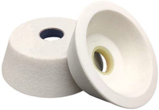
Figure 2.
White corundum bowl-shaped grinding wheel.
2.2. Contact Analysis of Grinding Tools and Workpieces
The grinding performance of a grinding tool depends on the contact state between the grinding head and the workpiece. A surface with a large radius of curvature can be approximated as a plane, while a complex surface with a small radius of curvature can be simplified as a cylindrical concave surface with the same curvature. Contact analysis between the bowl-shaped grinding wheel and these two types of surfaces can be conducted separately.
When grinding a flat surface, the end face of the bowl-shaped grinding wheel makes full contact with the workpiece surface. Although both the workpiece and the grinding wheel undergo minimal deformation under applied force, the pressure near the inner or outer rim of the bowl-shaped grinding wheel is higher than that at the middle position. Nevertheless, the overall pressure distribution across the wheel’s end face remains relatively uniform. When grinding a curved surface with a bowl-shaped grinding wheel, due to the inherent rigidity of the wheel, its end face cannot fully conform to the workpiece’s curved surface. To address this, a contact approach is adopted, in which the end face of the bowl-shaped grinding wheel is aligned perpendicular to the normal of the curved surface. In this configuration, the two ends of the grinding wheel come into contact with the workpiece—specifically, the wheel first contacts the regions of the curved surface with the maximum curvature. In practical grinding operations, this contact method tends to grind the areas initially contacted by the two ends of the wheel first. Only when the grinding depth is increased does the middle region get ground. This grinding method not only damages the profile of the blade surface but also compromises its dimensional accuracy, making it unsuitable for practical grinding applications.
When in vertical contact, the bowl-shaped grinding wheel comes into contact with the curved workpiece as shown in Figure 3a. The vertical height from the lower end face of the bowl-shaped grinding wheel to the bottom of the curved surface, as well as the radius of curvature of the workpiece, is shown in Figure 3b. Assuming the radius of curvature of the workpiece is R, the diameter of the bowl-shaped grinding wheel’s end face is D, and the farthest distance between the bottom of the bowl-shaped grinding wheel and the workpiece’s curved surface is hmax, we can derive the following equation:
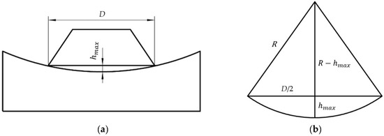
Figure 3.
Inclined contact analysis of a bowl-shaped grinding wheel and a curved surface: (a) the vertical contact state between a bowl-shaped grinding wheel and a curved object; (b) the relationship between curvature and height difference.
When the bowl-shaped grinding wheel is tilted into contact with the curved surface, as shown in Figure 4, according to Equation (3), the value of the inclination angle should be greater than or equal to for the top position of the bowl-shaped grinding wheel end face to contact the curved surface. However, the inclination angle of the bowl-shaped grinding wheel should not be too large; otherwise, it will cause instability in the grinding force.
where is the height between the bottom of the bowl-shaped grinding wheel and the workpiece’s curved surface (mm), and is the diameter of the bowl-shaped grinding wheel’s end face (mm).
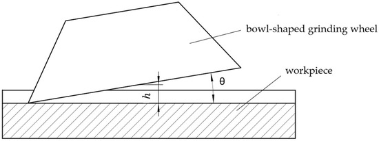
Figure 4.
The inclined contact of the bowl-shaped grinding wheel with the curved surface.
Combining Equations (2) and (3), when the diameter of the grinding wheel D is 75 mm, the relationship between the curvature radius of the workpiece and the minimum inclination angle of the bowl-shaped grinding wheel is calculated, as shown in Figure 5. It can be seen from the figure that as the curvature radius of the workpiece increases, the minimum inclination angle of the bowl-shaped grinding wheel decreases; when the curvature radius of the workpiece exceeds 500 mm, the rate of decrease slows down and tends to 1°.
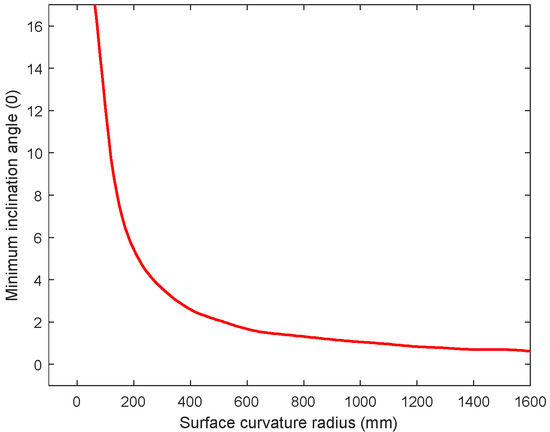
Figure 5.
Relationship of inclination of bowl-shaped grinding wheel and radius of object.
When grinding curved workpieces, it is better to tilt the bowl-shaped grinding wheel at a certain angle along the direction of the maximum vertical curvature of the workpiece for a better contact effect, and the contact area will be distributed on one side of the grinding wheel–workpiece interface. The contact area decreases as the inclination angle of the bowl-shaped grinding wheel increases, while the contact stress increases accordingly. However, the inclination angle should not be excessively large; an excessively large angle will cause the contact surface of the bowl-shaped grinding wheel to be concentrated on a small area. Therefore, a reasonable inclination angle must be selected based on actual grinding conditions to balance contact effect, contact area, and contact stress.
2.3. Grinding Force Analysis Based on the Bowl-Shaped Grinding Wheel
Grinding force is one of the important factors affecting the grinding effect, which is generated by the contact between the grinding wheel abrasive particles and the workpiece during the grinding process. The grinding force is composed of the contact force and additional forces. The grinding force is composed of the contact force and additional forces. The contact force is a general term for all interaction forces directly generated in the contact area between the grinding wheel and the workpiece, and it is usually related to the direct measurement values of sensors in engineering. In engineering, the contact force accounts for more than 90% of the grinding force. The additional forces have an extremely small impact on the magnitude, direction, and variation trend of the grinding force and can thus be ignored. Therefore, in engineering, the grinding force is usually equated to the contact force. Grinding force not only induces surface deformation of the workpiece, but also generates grinding heat and vibration during machining—both of which affect machining quality and accuracy. Grinding force generally acts in three perpendicular directions, namely the normal grinding force along the radial direction of the grinding wheel, the tangential grinding force along the tangential direction, and the axial grinding force along the axial direction. Due to the large negative rake angle of the grinding wheel abrasive grains, ; thus, the axial force is negligible. When grinding surfaces with a large curvature radius, the inclination angle of the bowl-shaped grinding wheel is generally very small, and the horizontal component of the normal force can also be ignored. Therefore, when grinding large curvature radius surfaces, the grinding force of the bowl-shaped grinding wheel can be decomposed into normal grinding force along the normal direction of the contact interface and tangential grinding force perpendicular to this normal direction, as shown in Figure 6.
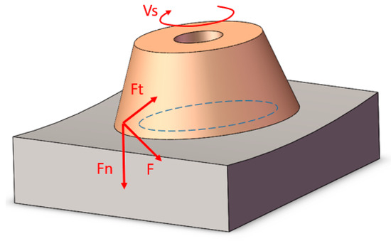
Figure 6.
The grinding force of the bowl-shaped grinding wheel.
The main parameters of grinding include grinding pressure, bowl-shaped grinding wheel speed, feed rate, and mesh size. At present, researchers around the world have conducted extensive studies on the removal model in grinding, most of which are based on the classical Preston material removal equation. The Preston equation approximates the grinding process as a linear machining process, and is expressed as [32]
where is the material removal depth per unit time, is the Preston constant, is the pressure exerted by the abrasive on the interface, is the sliding speed between the workpiece and the abrasive at the contact point, and is the unit time.
Although the end face of the bowl-shaped grinding wheel is a rigid plane, its contour is a circular ring. By tilting the bowl-shaped grinding wheel to contact the curved workpiece surface, its contour curve can be made to conform to the curved surface, as shown in Figure 7a. The contact method is set to Bonded contact, and the lower end face of the workpiece is subjected to fixed constraints. A load of 15 N is applied to the upper end face of the bowl-shaped grinding wheel. The simulation results are shown in Figure 7b. From the simulation results, it can be seen that when the bowl-shaped grinding wheel is tilted for grinding, the contact between the wheel and the curved surface is distributed on one side, the contact area is continuous, and the pressure distribution is relatively uniform.
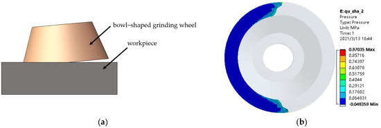
Figure 7.
Analysis of inclined contact between the bowl-shaped grinding wheel and the curved surface: (a) the inclined contact between the wheel and the curved surface; (b) the contact stress between the wheel and the curved surface.
During the grinding process, referring to the simulation results in Figure 7b, the contact area can be approximated as shown in Figure 8. Here, and are the inner and outer radii of the end face of the bowl-shaped grinding wheel, and is the angle of the bowl-shaped grinding wheel’s contact area.
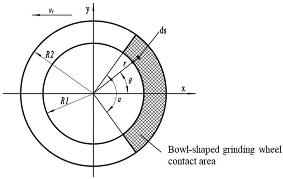
Figure 8.
Simplified diagram of bowl-shaped grinding wheel grinding area.
At time , the grinding force on the elemental area is , and the pressure on this element area can be expressed as
Assuming that the bowl-shaped grinding wheel rotates at a constant angular speed, the contact area element on its end face and its velocity can be expressed as
Based on Equations (4)–(7), the normal grinding force can be expressed as
The tangential grinding force can be expressed as
where is the normal grinding force, is the tangential grinding force, is the stiffness coefficient of the grinding system, is the density coefficient of the grinding wheel’s abrasive grains, is the feed speed, the is the linear velocity of the grinding wheel, is the grinding depth, is the diameter of the equivalent grinding wheel, and are indices related to the materials of the grinding wheel and workpiece, and is the proportionality coefficient between and which is usually taken as 0.2–0.5.
The normal grinding force mainly achieves the pressing effect between the bowl-shaped grinding wheel and the workpiece surface, while the tangential grinding force achieves the material removal effect on the workpiece surface. The normal grinding force has a direct impact on the frictional force between the abrasive particles of the grinding wheel and the workpiece surface. This study takes the normal grinding force as the control objective. According to Equation (9), the components of the grinding force are proportional to each other. When the grinding conditions are constant, the desired normal grinding force can be set to control the overall grinding force.
3. Adaptive Impedance Control Strategy for Grinding Force in Forgings
3.1. Position-Based Impedance Control Model
Impedance control integrates force control and position control by analyzing the dynamic relationship between the robot’s end-effector position and contact force, and thereby achieves force–position control using a unified control strategy [14]. The essence of impedance control lies in establishing a dynamic model between the robot’s end-effector position and the contact force; this model refers to the mass–spring–damping model shown in Figure 9.
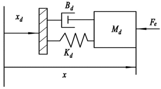
Figure 9.
Mass–spring–damping model.
From the impedance control model, its mathematical expression can be derived, and the model is as follows:
where is the inertia matrix; is the damping matrix; is stiffness matrix; is the end-effector acceleration; is the end-effector velocity; is the end-effector position; is the expected acceleration; is the expected velocity; is the expected position; and is the contact force.
The coefficients of , , and are all defined as n-dimensional positive definite matrices, where n is the dimension of the robot workspace. Thus, different control effects can be achieved by adjusting these coefficients.
In practical applications, impedance control can be divided into force-based and position-based impedance control according to its mode of action. For force-based impedance control, the inner loop is a force control loop, and the outer loop is an impedance calculation loop. The reference force is first calculated via the impedance outer loop and then input to the force control inner loop. Tracking of the desired force is achieved by adjusting the robot’s joint forces. This method requires high accuracy of the robot dynamics model and precise control over the robot’s motor torque. Most existing robot controllers are closed-loop systems, and they require the installation of torque sensors at the joints—this is costly and difficult to implement. Position-based impedance control consists of an inner position control loop and an outer impedance calculation loop. First, a position correction value is generated via the outer impedance loop. Then, the reference position, actual position, and position correction value are input to the robot’s inner position control loop, which controls the robot’s position to track the desired position—thus achieving the target dynamic relationship between the robot and the environment during contact. In the grinding process, due to the closed-loop nature of the robot controller, only position control of the robot can be implemented.
In position-based impedance control, the measured contact force acquired via a force sensor is subtracted from the expected contact force to yield the contact force deviation. The impedance model then generates the position correction value, and the robot adjusts its motion trajectory based on this value to eliminate the position deviation and drive the robot to the desired position—thus achieving tracking of the expected contact force. Substituting and into Equation (10) transforms the impedance control model into the following equation:
In the frequency domain, the impedance function can be expressed as
The position-based impedance control model, as shown in Figure 10, follows these specific steps in practical application: First, the force sensor collects the force data for the current cycle, and gravity compensation is applied to this data to yield the actual contact force . This force is then subtracted from the desired force to obtain the force deviation . The force deviation is input to the designed impedance control model, which then calculates the position offset for the current cycle in discrete form. This offset is added to the reference position to generate a new desired position , which is then input to the position controller. Through robot kinematic transformation and dynamic response, the robot moves to the new desired position and proceeds to the next control cycle. The robot then collects force data again and repeats the above steps, thereby implementing closed-loop control.
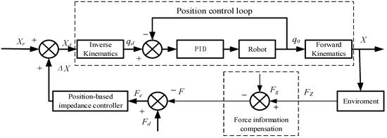
Figure 10.
Position-based impedance control model.
In actual grinding, only the normal grinding force needs to be controlled; thus, the position-based impedance control model can be applied to a single dimension, with the scalar parameters , , , and used instead of the multi-dimensional matrices , , , and . The time-domain expression of the impedance control model for this single dimension is
There are two working states for robots during grinding: free space and constrained space. The free space state refers to the condition where the robot is not affected by external contact forces when approaching or moving away from the workpiece, while the constrained space state is the condition where it is subjected to contact forces during workpiece grinding. In the process of free space motion, the end effector does not experience environmental contact forces; that is, , and the impedance control model is modified to the following equation:
when the robot’s expected force and , can be obtained, and the robot’s spatial control can be simplified to position control.
When the robot is grinding, contact force exists between the end-effector and the workpiece, forming a dynamic system together with the environmental system. The contact state during the grinding process is simplified as a rigid spring, as shown in Figure 11.
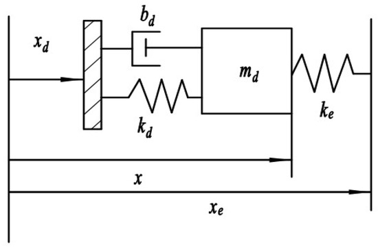
Figure 11.
Impedance control model with environmental mode.
The coefficients , , and in Figure 11 represent the mass coefficient, damping coefficient, and stiffness coefficient of the robot system, represents the environmental stiffness, represents the environmental position, and represents the actual position of the robot. The environmental model can be expressed as
3.2. Steady-State Error Analysis of Impedance Control
Assuming that the robot’s position control system is ideal, that is , and based on this assumption, considering the single-degree-of-freedom case, the difference between the desired contact force and the actual contact force at the robot’s end-effector is
By substituting the environmental model from Equation (15) into Equation (16), the following equation is obtained:
According to the impedance control diagram in Figure 10, substitute Equation (17) into Equation (11) and eliminate . Over a short period of time, the contact force between the robot and the environment, and the desired position remain constant (treated as constants). Therefore, , and the differential equation of the impedance control model is obtained as follows:
When the robot reaches a steady state, the steady-state error is
The expression for the actual contact force is
The coefficient is the equivalent stiffness coefficient of the environment and target impedance, expressed as (N/m). From Equation (19), it can be seen that the steady-state contact force error is related to the target stiffness coefficient , environmental stiffness coefficient , and environmental position . When the reference trajectory satisfies the equation , the steady-state contact force error is zero. If the environmental stiffness coefficient and environmental position are known, the reference trajectory can be calculated. When the robot moves along the reference trajectory , accurate tracking of the desired force can be achieved. However, the equivalent environmental stiffness coefficient and environmental position are both unknown and cannot be measured in real-time. The most direct solution is to estimate them online and address this issue via an adaptive algorithm for online estimation of environmental stiffness and environmental position.
3.3. Adaptive Impedance Controller
In the actual grinding process, the grinding environment is highly complex, and the environmental stiffness and position may change at any time—this will have a significant impact on the performance of the control system. The position-based impedance control model cannot adjust the target impedance parameters in real time according to changes in environmental stiffness and position during system operation; consequently, it may fail to achieve the desired grinding effect or even complete the grinding task. Real-time online estimation of the environmental stiffness coefficient and environmental position can eliminate environmental parameter errors and enhance the adaptability of the control systems. Specifically, real-time estimation of environmental stiffness and position—implemented via adaptive parameter estimation—is used to modify the reference trajectory. The model diagram is shown in Figure 12.
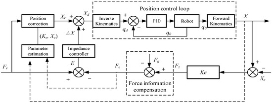
Figure 12.
Adaptive position–impedance control model.
When the steady-state contact force error , the target reference trajectory is given by , and the estimated reference trajectory is defined as
Assuming , the relationship is as follows:
The parameter estimation of Equation (22) is as follows:
where is the estimated value of actual contact force , and is the estimated value of parameter ; their units are N and N/m, respectively.
Let and . Define the vector ; then the formula difference can be derived as
The coefficients of and can be adjusted using the difference , where is the estimated environmental contact force and is its actual value. At time , and based on Equations (22) and (23), the resulting equation is given by
According to the impedance control model, eliminating from the equation yields
The condition for the above equation to hold is or . Since , and its estimated value is also positive, is impossible. Thus, the only valid condition is , which implies . Furthermore, under the conditions of and , we can confirm .
Given a reasonable value of , to ensure the convergence of and obtain , and by analyzing with the Lyapunov asymptotic stability theorem, the system state equation of the state vector is defined as follows:
where is a diagonal positive definite constant matrix, and .
Based on Equation (24), under the condition of , the unique equilibrium state of the system is , that is , . A positive definite function is defined as follows:
The Lyapunov energy function is not unique, as long as it satisfies the stability theorem. Its first derivative with respect to time is given by
Obviously, this is a negative semi-definite matrix, which satisfies the Lyapunov stability theorem, and the system is asymptotically stable at the origin . when , if , then .
By evolving Equation (27), we can obtain
where and are positive real constants.
So the complete adaptive algorithm can be expressed as
3.4. Adaptive Impedance Control Simulation
The adaptive impedance control model was established using MATLAB R2023a Simulink software, as shown in Figure 13. Simulation analysis was conducted using a unidirectional adaptive algorithm. In reality, environmental stiffness is not a fixed value and varies depending on the processing condition. The grinding object was set as stainless steel blades with a stiffness coefficient of approximately 20,000 N/m. Both the stiffness coefficient of the robot system and the initial estimated environmental stiffness coefficient were set to 20,000 N/m. Given that the designed grinding tool weights about 3 kg, the system mass coefficient was set to 3 kg, and the initial estimated environmental position was set to 0.013 m. In the impedance control simulation of a robotic grinding system, the damping coefficient is a core parameter that balances the system’s dynamic response, stability, and grinding quality. In engineering applications, for industrial robots with a load capacity of 10–50 kg, the value range of is 200–500 N·s/m. For the high-disturbance simulation analysis of the 3.4 single-direction adaptive algorithm, we selected = 500 N·s/m to suppress fluctuations. Based on previous experience in parameter setting for robotic grinding or similar motion control, for robotic grinding systems that require both grinding accuracy and efficiency, the common empirical value ranges for the positive real constants and are 5–15 and 8–20, respectively. For the high-disturbance simulation analysis of the unidirectional adaptive algorithm in Section 3.4, we select = 10 and = 20 to ensure grinding accuracy while enhancing the system’s adjustment capability. Table 1 presents the detailed control parameters of the adaptive impedance controller. In an actual grinding environment, the grinding force is expected to remain constant, but the environmental stiffness or position may change. The key control requirement for adaptive impedance control is that when the environmental stiffness or position changes, the contact force can be quickly adjusted to the desired force value within 0.5 s.
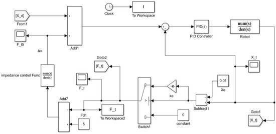
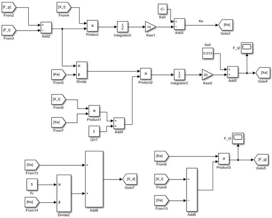
Figure 13.
Simulation model of the adaptive impedance control model in MATLAB/Simulink.

Table 1.
Control parameters of adaptive impedance controller.
3.4.1. Simulation of Changing Environmental Positions
Set the desired force to 5 N, the environmental stiffness to 15,000 N/m, and the initial position of the environment to 0.01 m. At 2.5 s into the simulation, suddenly change to 0.009 m, as shown in Figure 14. At the moment the robot contacts the workpiece, a maximum collision contact force of 15 N is generated. After approximately 0.5 s, the contact force stabilizes. When the environmental position changes suddenly, the contact force oscillates significantly but quickly regains stability within 0.5 s. The system exhibits strong error adjustment capability, and the adaptive impedance control demonstrates good adaptability to sudden changes in the environmental position.
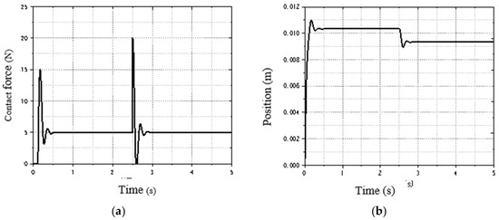
Figure 14.
Simulation of abrupt change in environment position at 2.5 s: (a) force response curve of adaptive impedance; (b) position tracking curve of adaptive impedance control.
3.4.2. Simulation of Variable Environmental Stiffness
Set the expected force to 5 N, the environmental position to 0.01 m, and the initial environmental stiffness to 15,000 N/m. At 2.5 s into the simulation, suddenly changes to , as shown in Figure 15. When the robot contacts the workpiece, a maximum collision force of 15 N is generated, but it quickly adjusts to the desired force value and stabilizes. When the environmental stiffness changes suddenly, the grinding force oscillates slightly and gradually diminishes, stabilizing at the desired value. Therefore, the adaptive impedance model exhibits good adaptability to sudden changes in environmental stiffness.
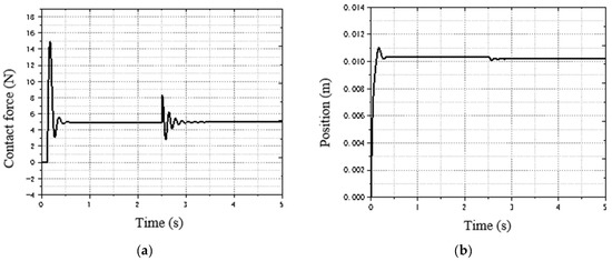
Figure 15.
Simulation of abrupt change in environment stiffness at 2.5 s: (a) force response curve of adaptive impedance; (b) position tracking curve of adaptive impedance control.
4. Dynamic Trajectory Planning of Automatic Grinding
4.1. Power Information Processing
The force sensor is installed between the robot end-effector and the grinding tool. The force component of the grinding tool’s self-weight in the sensor coordinate system varies with different postures, and the inertia of the grinding tool also affects the sensor measurement. To obtain the true contact force between the grinding tool and the workpiece, it is necessary to eliminate the influence of the grinding tool’s self-weight and inertia. Due to the grinding tool’s light weight, low speed, and low acceleration, the influence of inertia can be ignored, and only the effect of self-weight on the sensor readings needs to be considered. Therefore, the value measured by the sensor consists of the contact force between the grinding tool and the workpiece, and the self-weight force of the grinding tool:
The forces in Equation (32) are based on the sensor coordinate system. The self-weight force of the grinding tool varies with the posture in the sensor coordinate system. To obtain a more accurate actual contact force, it is necessary to remove the influence of the grinding tool’s self-weight from the sensor measurement.
Figure 16 shows the force diagram of the grinding tool, where is the robot’s base coordinate system, is the tool coordinate system, and is the sensor coordinate system. The homogeneous transformation matrix between the sensor coordinate system and the base coordinate system is
where is the rotation matrix, is the translation vector of the sensor’s zero point in the base coordinate system.
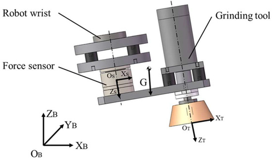
Figure 16.
Force analysis of grinding tool.
The robot used is an RPY robot, and the RPY angle is used to describe its posture. The angles of φ, θ, and ψ correspond to taxes A, B, and C in the robot controller, respectively, representing the rotation angles around the Z-axis, Y-axis, and X-axis of the base frame. This can be obtained as follows:
where s is sin, and c is cos.
Assuming the gravity of the grinding tool is G and its gravity in the base coordinate system is , the component of the grinding tool’s gravity in the sensor coordinate system can be obtained as follows:
where .
The actual contact force between the tool and the workpiece can be obtained as follows:
where is the actual grinding contact force, is the force measured by the sensor, and is the compensation force.
The angles of φ, θ, and ψ in the equation can be obtained from the robot controller. During grinding, the normal direction of the grinding tool is collinear with that of the grinding position. The normal force can be directly derived from the processed contact force .
4.2. Position Correction Quantity Acquisition
The acquisition of force sensor information is a discrete process. Therefore, in practical applications, it is necessary to convert the impedance control strategy from a continuous-time domain system to a discrete-time domain system. First, the differential term in the impedance control model needs to be discretized as follows:
Substitute the discretized differential term into Equation (13) and convert it into a differential equation based on the position-based impedance control model:
For Equation (38), it can be concluded that the discrete impedance control model is related to three consecutive position correction variables. To obtain the current position correction , the values of the previous two corrections and are required. Since the position correction has initial conditions, the first two initial position correction need to be set. These initial values are determined using a simplified impedance control model, as shown in the following equation:
The correction displacement corresponding to the initial deviation can be obtained from this equation. If the desired contact force for grinding is set to , then the normal force deviation is
By substituting the normal force deviation into the difference equation, the real-time position correction quantity can be obtained. Let the position points before and after correction be and , respectively, the direction of vector (from to ) is collinear with both the normal direction of the grinding point and the axial direction of the tool coordinate system. Therefore, by offsetting the position from to along the normal direction in the tool coordinate system, the tracking of the desired contact force can be achieved.
4.3. Dynamic Trajectory Programming
Due to errors in workpiece dimensions, clamping, and grinding tool installation, significant errors may lead to inaccurate positioning between the workpiece and the grinding tool. When the robot grinds along a fixed trajectory, it may result in empty grinding or over-grinding. To mitigate the impact of positioning errors, a constant normal force control strategy is adopted. Building on the impedance control strategy for a single position point, the robot’s end position needs to be continuously adjusted during the continuous grinding process to achieve dynamic planning of the grinding trajectory.
The dynamic trajectory planning method first records the initial grinding points along the workpiece surface to generate the initial grinding trajectory. Then, it corrects the unreasonable position of the initial trajectory using a constant normal force impedance control strategy to complete the entire machining process. The specific steps of initial trajectory planning are as follows: select target points appropriately within the machining area, move the robot to each target point, adjust it to a suitable posture, record the point information as a trajectory teaching point, and repeat the above operations sequentially for the remaining target points to complete the initial trajectory planning. Figure 17 and Figure 18 show the schematic diagram of dynamic trajectory adjustment and the flowchart of adaptive impedance control, respectively. The steps of dynamic trajectory adjustment are as follows: the robot first moves to the first initial grinding point, measures the normal force value at this point, and obtains a corrected grinding point via the impedance control strategy. This corrected point is derived from the initial teaching point and has high accuracy. Next, the robot is controlled to move to this corrected grinding point, where position and force information are collected to estimate the next reference position. Position compensation is then performed on the next initial grinding point to obtain a new reference position. Finally, the robot is controlled to move to this reference position, and the aforementioned correction and compensation process is repeated.
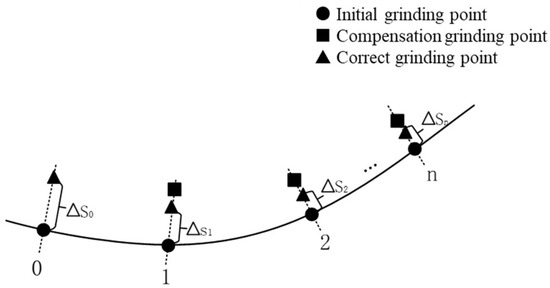
Figure 17.
Schematic diagram of trajectory dynamic adjustment.
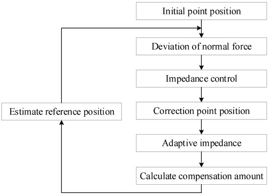
Figure 18.
Flow-chart of adaptive impedance control.
5. Grinding Experiment Verification
5.1. Experimental Setup
The experimental grinding object is a certain model of water turbine blade actually produced by the enterprise, as shown in Figure 19a. The blade material is stainless steel, with overall external dimensions of 1000 × 680 × 470 mm and a weight of approximately 600 kg. Based on the absolute curvature, the main surface of the blade can be divided into three zones via a cloud map and contour line visualization, as shown in Figure 19b. Among these, Zone 1 has an absolute curvature of 0.001–0.0033 mm−1, Zone 2 has an absolute curvature of 0.00058–0.001 mm−1, and Zone 3 has an absolute curvature ranging from 0.00016 to 0.00058 mm−1. The surface in Zone 1 has the highest curvature, while that in Zone 3 has the lowest. The absolute curvature within the same zone is relatively consistent, and variations in curvature have little impact on the grinding process. The overall scheme of the robotic automated grinding and processing platform system is shown in Figure 20, and Table 2 lists the main performance parameters of the grinding tool.
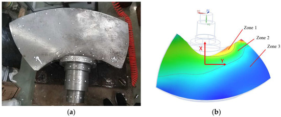
Figure 19.
Turbine blade and curvature-based partitioning: (a) turbine blade; (b) blade partition based on curvature.
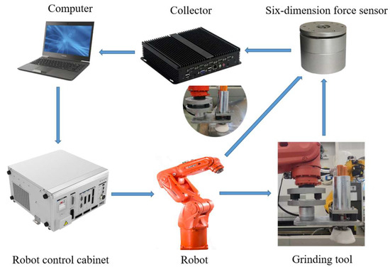
Figure 20.
Composition of robot grinding system.

Table 2.
Main performance parameters of grinding tool.
To ensure the normal operation of the robot grinding system, stable data transmission between its components must be guaranteed, including the robot controller, control PC, and six-axis force sensor. A reasonable communication scheme is the foundation for achieving stable control of the robot grinding system.
A 200 × 300 mm area on the surface was selected for the automated machining experiments, as shown in Figure 21a. The acquisition of a grinding trajectory is a critical link in robotic automated machining, as it significantly impacts grinding quality and processing efficiency. Common grinding paths include the Hilbert surround path, Zigzag scan path, and Spiral circular path. For this experiment, the grinding area near the blade tip edge was chosen. Due to the gentle curvature variation in this area, a Zigzag trajectory was adopted to guide the robot’s movement, as shown in Figure 21b. Based on the material removal formula (Equation (4)), the trajectory spacing was set to 20 mm, the grinding step size to 25 mm, and the feed step size to 20 mm.
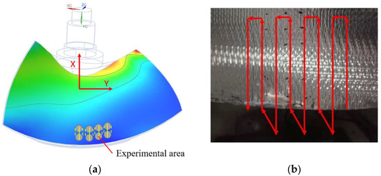
Figure 21.
Schematic diagram of grinding experiment: (a) experiment area; (b) scan path.
5.2. Experiment Results and Conclusions
Based on the analysis of grinding force in Chapter 2 and the data from our experimental platform, the grinding force is set as 4 N, 8 N, 12 N, and 16 N, and experiments are conducted separately. The curves of force data during the grinding process for a period of time are drawn, as shown in Figure 22. The grinding force fluctuates around the set value center, basically achieving stable control of the grinding force. As stated in Section 2.3, “This study takes the normal grinding force as the control objective.” Therefore, in our experimental analysis, the object of analysis is the normal grinding force proposed in Section 2.3, and the analysis results are shown in Figure 22. As shown in Figure 22a, with a given grinding force of 4 N, the maximum absolute value of the force fluctuation is 1.5 N, and the fluctuation percentage is 37.5%. As shown in Figure 22b, with a given grinding force of 8 N, the maximum absolute value of the force fluctuation is 1.5 N, and the fluctuation percentage is 18.8%. As shown in Figure 22c, with a given grinding force of 12 N, the maximum absolute value of the force fluctuation is 2.2 N, and the fluctuation percentage is 18.3%. As shown in Figure 22d, with a given grinding force of 16 N, the maximum absolute value of the force fluctuation is 2.7 N, and the fluctuation percentage is 16.9%. The fluctuation percentage is the smallest when the given grinding force is 16 N, which corresponds to the best grinding effect.
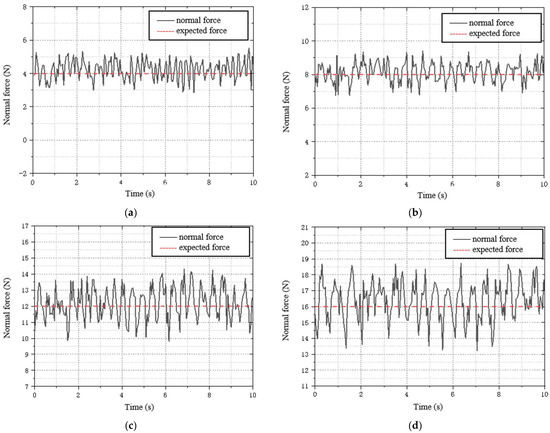
Figure 22.
Force curves from blade grinding experiments under different grinding forces: (a) F = 4 N; (b) F = 8 N; (c) F = 12 N; (d) F = 16 N.
The robot grinds according to the taught points. After 20 repeated machining cycles with the optimal grinding force of 16 N, the obvious knife marks on the blade surface disappear. Nine points were selected on the ground surface to measure roughness using a surface roughness tester, and the average value of the measurement results was calculated. The average surface roughness value was found to be , which is lower than the enterprise’s roughness of , indicating that the grinding quality meets the expected requirements. Since the experimental grinding area is 200 × 300 mm, the average total grinding time to meet the surface roughness requirement is approximately 11.2 min. Through calculation, the grinding efficiency is about 0.89 , which is higher than the enterprise’s efficiency of 0.47 . The surface of the ground blade is shown in Figure 23.
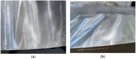
Figure 23.
The processed blade surface: (a) top view; (b) front view.
6. Conclusions and Future Remarks
This paper presents a dynamic trajectory planning method for the automatic grinding of large-curved forgings, based on an adaptive impedance control strategy. This method aims to achieve grinding force control, ensure grinding performance, and enhance grinding efficiency.
In response to the inability of some robot controllers to directly control joint motors, this paper proposes indirectly regulating the grinding force by controlling the end robot’s position. A position-based impedance control model is established, and the steady-state error of impedance control is studied theoretically. To address the limitation that the impedance control model cannot adjust impedance parameters online, an adaptive impedance controller based on the online estimation of environmental position and stiffness is adopted. The adaptability of the controller is simulated and analyzed, and the effectiveness and robustness of the adaptive algorithm are verified.
In response to the impact of the grinding tool’s self-weight on the force sensor readings under different postures, matrix transformation is used to convert gravity from the base coordinate system to the sensor coordinate system. The collected force information is compensated for gravity, and the force deviation information is input into a discretized impedance control algorithm to obtain the correction quantity for a single position point. A position-based adaptive impedance control strategy is then employed to dynamically plan the grinding trajectory and accomplish the force control task of the grinding process.
By constructing a robotic automatic grinding system and conducting grinding experiments on blades, the experimental results demonstrated the expected force control effect. The grinding system effectively removed tool marks on the blade surface, and both the post-grinding surface roughness and grinding efficiency exceeded the enterprise’s expected values.
This paper only focuses on the main blade surface, which has a relatively larger area. For the transition surface of the blade root with a smaller radius of curvature, the robot cannot reach it due to its location in the middle of the blade and the current robot installation position; additionally, a dedicated grinding tool for this transition surface has not yet been designed. For the transition surface, analysis of manual grinding experiments suggested that tool design could adopt a bowl-shaped grinding wheel with a smaller diameter or a flexible grinding head, such as a flap wheel. Furthermore, after implementing the trajectory planning function, the robot’s grinding path and pose can be optimized by integrating the surface characteristics, thereby achieving better grinding results. In addition, during robotic grinding, the grinding tool will fail as grinding time increases, rendering it unable to continue grinding. Future work could involve in-depth exploration of the relationship between grinding tool failure time and the grinding parameters, establishment of a tool failure time database, and estimation of tool failure time via prediction algorithms. Furthermore, due to limitations in experimental funding and space, we could only conduct experimental verification on a portion of the blades to confirm the feasibility of our proposed method. For experiments on the entire blade, we will communicate with the enterprise in the follow-up to build an experimental platform, which will be used for both experimental verification and production promotion.
Author Contributions
Conceptualization, L.L.; methodology, L.L.; investigation, K.Q. and C.H.; software, K.Q. and C.H.; validation, L.L., K.Q., and C.H.; data curation, L.L. and C.H.; writing—original draft preparation, L.L.; writing—review and editing, L.L., K.Q., and C.H.; project administration, L.L. All authors have read and agreed to the published version of the manuscript.
Funding
This research was funded by the Project of Zhejiang Provincial Department of Science and Technology (No. LS18E05003) and the Horizontal research Project (No. 2 KYY-HX-20230466).
Data Availability Statement
Data available on request.
Conflicts of Interest
The authors declare no conflicts of interest.
References
- Kafle, A.; Shrestha, P.; Chitrakar, S.; Thapa, B.; Thapa, B.S.; Sharma, N. A review on casting technology with the prospects on its application for hydro turbines. J. Phys. Conf. Ser. 2020, 7, 12015. [Google Scholar] [CrossRef]
- Prabhakar, A.; Papanikolaou, M.; Salonitis, K.; Jolly, M. Minimising defect formation in sand casting of sheet lead: A DoE approach. Metals 2020, 10, 252. [Google Scholar] [CrossRef]
- Wang, M.; Song, Y.; Wang, P.; Chen, Y.; Sun, T. Grinding/Cutting Technology and Equipment of Multi-scale Casting Parts. Chin. J. Mech. Eng. 2022, 35, 97–105. [Google Scholar] [CrossRef]
- Fan, J.; Xue, L.; Liu, Y.; Li, W. Reliability analysis of spindle system of CNC grinder based on fault data. Int. J. Adv. Manuf. Technol. 2021, 117, 3169–3183. [Google Scholar] [CrossRef]
- Wang, S.; Xia, M.; Ma, C.; Dong, J.; Wang, S.; Wang, J. A novel flank correction method for face gear ground by CNC worm wheel grinder. Mech. Mach. Theory 2023, 189, 105435. [Google Scholar] [CrossRef]
- Ge, J.; Deng, Z.; Li, Z.; Li, W.; Lv, L.; Liu, T. Robot welding seam online grinding system based on laser vision guidance. Int. J. Adv. Manuf. Technol. 2021, 116, 1737–1749. [Google Scholar] [CrossRef]
- Xiao, G.; Zhang, T.; He, Y.; Zheng, Z.; Wang, J. The robot grinding and polishing of additive aviation titanium alloy blades: A review. J. Int. Manuf. Spec. Equip. 2024, 5, 34–54. [Google Scholar] [CrossRef]
- Zhao, H.; Wen, K.; Lei, T.; Xiao, Y.; Pan, Y. Automatic Aluminum Alloy Surface Grinding Trajectory Planning of Industrial Robot Based on Weld Seam Recognition and Positioning. Actuators 2023, 12, 170. [Google Scholar] [CrossRef]
- Wang, Z.; Zou, L.; Luo, G.; Lv, C.; Huang, Y. A novel selected force controlling method for improving robotic grinding accuracy of complex curved blade. ISA Trans. 2022, 129, 642–658. [Google Scholar] [CrossRef]
- Vetter, N.; Beuss, F.; Jentsch, A.; Fruendt, S.; Sender, J.; Fluegge, W.; Kloetzer, C. Automatic offline path planning of robots grinding multi-curved surfaces on large ship propellers-A human-in-the-loop approach. Procedia CIRP 2023, 120, 934–939. [Google Scholar] [CrossRef]
- Li, L.; Wang, Z.; Zhu, G.; Zhao, J. Position-based force tracking adaptive impedance control strategy for robot grinding complex surfaces system. J. Field. Rob. 2023, 40, 1097–1114. [Google Scholar] [CrossRef]
- Wang, P.; Xu, Q. Design and modeling of constant-force mechanisms: A survey. Mech. Mach. Theory 2018, 119, 1–21. [Google Scholar] [CrossRef]
- Fu, L.; Zhao, J. Maxwell-Model-Based Compliance Control for Human-Robot Friendly Interaction. IEEE Trans. Cognit. Dev. Syst. 2021, 13, 118–131. [Google Scholar] [CrossRef]
- Hogan, N. Impedance Control an Approach to Manipulation. J. Dyn. Syst. Meas. Control 1985, 107, 1–7. [Google Scholar] [CrossRef]
- Izadbakhsh, A.; Khorashadizadeh, S.; Ghandali, S. Robust adaptive impedance control of robot manipulators using Szász–Mirakyan operator as universal approximator. ISA Trans. 2020, 106, 1–11. [Google Scholar] [CrossRef] [PubMed]
- Liang, J.; Zhong, H.; Wang, Y.; Chen, Y.; Zeng, J.; Mao, J. Adaptive Force Tracking Impedance Control for Aerial Interaction in Uncertain Contact Environment Using Barrier Function. IEEE Trans. Auto Sci. Eng. 2024, 21, 4720–4731. [Google Scholar] [CrossRef]
- Kim, T.; Yoo, S.; Seo, T.; Kim, H.; Kim, J. Design and Force-Tracking Impedance Control of 2-DOF Wall-Cleaning Manipulator via Disturbance Observer. IEEE/ASME Trans. Mech. 2020, 25, 1487–1498. [Google Scholar] [CrossRef]
- Xie, Z.; Yan, Z. Varying rate adaptive hybrid position—Impedance control for robot-assisted ultrasonic examination system. Mech. Sci. 2022, 13, 559–575. [Google Scholar] [CrossRef]
- Cao, R.; Cheng, L.; Li, H. Passive Model-Predictive Impedance Control for Safe Physical Human–Robot Interaction. IEEE Trans. Cogn. Dev. Syst. 2024, 16, 426–435. [Google Scholar] [CrossRef]
- Dong, B.; Li, S.; An, T.; Cui, Y.; Zhu, X. Decentralized variable impedance control of modular robot manipulators with physical human–robot interaction using Gaussian process-based motion intention estimation. Neur. Comput. Appl. 2024, 36, 6757–6769. [Google Scholar] [CrossRef]
- Wu, C.; Guo, K.; Sun, J. Dual PID Adaptive Variable Impedance Constant Force Control for Grinding Robot. Appl. Sci. 2023, 13, 11635. [Google Scholar] [CrossRef]
- Li, X.; Zhao, H.; Zhou, H.; Cai, Y.; Yin, Y.; Ding, H. Robotic grinding and polishing of complex aeroengine blades based on new device design and variable impedance control. Robot. Comput. Integr. Manuf. 2025, 92, 102875. [Google Scholar] [CrossRef]
- Li, L.; Lu, B.; Jiang, M.; Gao, L.; Sun, Y. Robotic normal constant force polishing of unknown-model workpieces using variable impedance control. J. Manuf. Proc. 2025, 153, 268–279. [Google Scholar] [CrossRef]
- Jia, L.; Chen, K.; Liao, Z.; Qiu, A.; Cao, M. Adaptive Robust Impedance Control of Grinding Robots Based on an RBFNN and the Exponential Reaching Law. Actuators 2025, 14, 393. [Google Scholar] [CrossRef]
- Xu, D.; Yin, L.; Wang, J. Grinding force estimation and control of grinding robot with variable impedance control strategy. Int. J. Adv. Manuf. Technol. 2025, 137, 2011–2027. [Google Scholar] [CrossRef]
- Yan, Z.; Zhao, H.; Miao, X.; Gao, B. Design and trajectory optimization of a large-diameter steel pipe grinding robot. J. Pipeline Syst. Eng. Pract. 2024, 15, 04024020. [Google Scholar] [CrossRef]
- Meng, Y.; Jiang, Y.; Li, Y.; Pang, G.; Tong, Q. Research on Point Cloud Processing and Grinding Trajectory Planning of Steel Helmet Based on 3D Scanner. IEEE Access 2024, 12, 3085–3097. [Google Scholar] [CrossRef]
- Li, M.; Wang, W.; Zhang, J.; Wang, C.; Zou, L.; Huang, Y. Robotic accurate grinding of complex surfaces with 3D-printed compliant tool featuring internal-blade structure. J. Manuf. Proc. 2025, 148, 375–385. [Google Scholar] [CrossRef]
- Zhu, Y.; Wang, X.; Wang, Y.; Zhou, X.; Zhang, H.; Wan, Y. Robot trajectory planning for gear chamfer grinding based on multi-objective collaborative optimization and quintic B-spline interpolation algorithm. Int. J. Adv. Manuf. Technol. 2025, 138, 4397–4414. [Google Scholar] [CrossRef]
- Shan, Z.; Cai, Z.; Chen, T.; Chen, Z.; Hu, Y. A Trajectory planning technique for grinding and polishing aerospace turbine blades’ thermal barrier coatings based on PCL point cloud processing. Proc. Inst. Mech. Eng. B J. Eng. Manuf. 2025, 239, 1564–1579. [Google Scholar] [CrossRef]
- Khan, H.; Lee, M.C.; Suh, J.; Kim, R. Enhancing Robot End-Effector Trajectory Tracking Using Virtual Force-Tracking Impedance Control. Adv. Intell. Syst. 2025, 7, 2400380. [Google Scholar] [CrossRef]
- Yang, P.; Yang, B.; Wu, R. A robot intelligent polishing system for fiber-reinforced plastics (FRP) material combined with online measurement. Int. J. Adv. Manuf. Technol. 2025, 140, 799–817. [Google Scholar] [CrossRef]
Disclaimer/Publisher’s Note: The statements, opinions and data contained in all publications are solely those of the individual author(s) and contributor(s) and not of MDPI and/or the editor(s). MDPI and/or the editor(s) disclaim responsibility for any injury to people or property resulting from any ideas, methods, instructions or products referred to in the content. |
© 2025 by the authors. Licensee MDPI, Basel, Switzerland. This article is an open access article distributed under the terms and conditions of the Creative Commons Attribution (CC BY) license (https://creativecommons.org/licenses/by/4.0/).