Abstract
The suspension system can adapt to different road excitations by adjusting its own stiffness or damping, or outputting active driving force, thereby improving the comprehensive dynamic performance of the vehicle, including ride comfort and vehicle handling. As the automotive industry’s requirements for “intelligence, comfort, and safety” continue to increase, the intelligence of suspension systems has become a research hotspot for scientific research institutions and enterprises, with broad development prospects. This article reviews the current development status of automotive suspensions and introduces the working principles and research status of different types of suspension systems, such as passive suspensions, semi-active suspensions, active suspensions, and electromagnetic suspensions. In addition, it summarizes the control methods of vehicle intelligent suspensions, including classical control, modern control, and intelligent control, and expounds the advantages and disadvantages of each control strategy. Finally, it summarizes the challenges and development trends faced by suspension systems. This review can provide technical reference for researchers engaged in the study of intelligent suspension under the modern chassis architecture and offer direction guidance for the development of key suspension technologies.
1. Introduction
As an indispensable means of transportation in people’s daily lives, consumers’ demand for automobile performance is increasing. Ride comfort and handling stability are regarded as key indicators to judge automobile performance. However, the traditional passive suspension system is limited by its fixed characteristics, and it is difficult to meet the dual requirements of comfort and handling stability under different road conditions. Therefore, research on suspension with controllable performance has become a hotspot in the field of automotive engineering [1,2,3]. With the development of microcomputer technology and control algorithms, the suspension system has been constantly updated [4,5].
Suspension is the general name of the force transmission connection device between the vehicle body and the wheels, transmitting the force and moment of the road acting on the wheels to the body and absorbing and mitigating the impact [6,7]. In the early stages of suspension development, cars used simple steel springs as shock absorbers. As people’s demand for driving stability and ride comfort increased, various types of suspension systems emerged. The stiffness and damping parameters of the traditional passive suspension are fixed, which cannot be controlled according to the driving conditions. But, its advantage is low cost. Unlike the traditional suspension, the intelligent suspension can dynamically adjust the system stiffness, damping, and other parameters or output a controllable suspension force according to the motion state and road conditions, ensuring comfort and handling stability simultaneously [8]. The system structure and control algorithm of intelligent suspension are constantly improved and optimized, and the intelligent degree of the chassis is continuously improved, with the continuous progress of material science and electronic control [9,10]. Nevertheless, the development of intelligent suspension systems also faces a series of challenges. How to further improve the stability and reliability of the suspension system, develop more efficient and adaptable control algorithms, and reduce system energy consumption and cost have become urgent problems for the current intelligent suspension.
In order to deeply explore the research status of automotive suspensions and their control methods, this paper reviews the main classifications and working principles of suspension systems. The research status of suspensions is shown in Figure 1. According to the differences in actuators, they can be divided into four categories: passive suspensions, semi-active suspensions, active suspensions, and electromagnetic suspensions. At the same time, this paper introduces the mainstream control strategies, including classical control, modern control, and intelligent control, and analyzes and summarizes the advantages and disadvantages of various control methods. Finally, it sorts out the current challenges and future development trends of suspensions, aiming to provide technical reference for researchers of suspensions in the field of automotive steer-by-wire chassis.
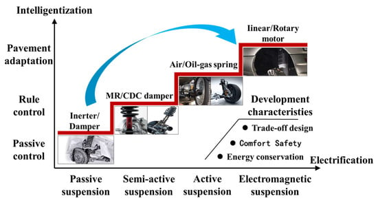
Figure 1.
The research history of automotive suspensions.
2. New Passive Suspension
The new passive suspension system primarily consists of high-performance elastic elements and optimized damping elements. The core of the system lies in its innovative damping element, which automatically adjusts its damping force characteristics based on the suspension’s speed without relying on sensors, controllers, or external energy input. Unlike semi-active and active suspension systems, the new passive suspension requires no additional energy, offering advantages such as simple structure, high reliability, and low maintenance costs.
2.1. Traditional Suspension
The traditional passive suspension system is mainly composed of springs and dampers, as shown in Figure 2, and the mathematical models of passive suspension are detailed in Appendix A.1. Because of its low cost and simple structure, it has become the most widely used suspension structure. The damping coefficient and stiffness coefficient of passive suspension are pre-set during the vehicle manufacturing process, which limits the vehicle’s adaptability to different road conditions. High damping and high stiffness normally result in good road handling, while low damping or stiffness enhances ride comfort, but roll and pitch control are poor. Obviously, the passive suspension system with only a “spring-damper” structure can hardly effectively achieve a balance between comfort and handling stability. Therefore, variable topology and other structural types of components are gradually introduced into the design of suspension systems [11,12].
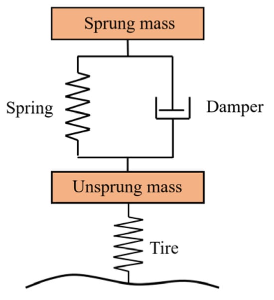
Figure 2.
Principle of passive suspension.
2.2. Variable Structure Suspension
The variable structure suspension, generally composed of actuators and control units, dynamically adjusts the suspension performance by controlling the suspension geometry of the vehicle and then controlling the wheel alignment parameters in real-time, such as camber angle and toe angle. The variable structure suspension first appeared in the rear suspension of a motorcycle. It is realized by adjusting the position of the connecting point on the rear spring shock absorber group of the motorcycle [13].
Lee [14,15] developed a variable structure suspension with active wheel toe angle. By adjusting the position of the installation point of the rear wheel connecting rod through the actuator, the wheel can produce the best toe angle and improve the steering performance of the vehicle. Goodarzi [16] improved the analysis and control of this structure and studied the influence of geometric structure changes on the roll center height and toe angle. Nemeth [17,18] proposed an active variable structure suspension that changes the camber angle of the wheel according to the driver’s steering angle and gave the structural scheme and robust control method. The steering ability and stability of the vehicle are improved, and the steering angle required by the front wheel is reduced. Gaspar [19] changed the camber angle of the wheel by generating differential torque and auxiliary front wheel steering angle through the control system and improved the road tracking ability. Park [20] established a vehicle model and its control strategy to control the camber angle of the front suspension, which reduces the camber angle and thrust in the turning state. As shown in Figure 3, the system adjusts the relative position of the spring-damper group and the suspension by changing the angle of the connecting rod GF, thereby improving comfort and body posture.
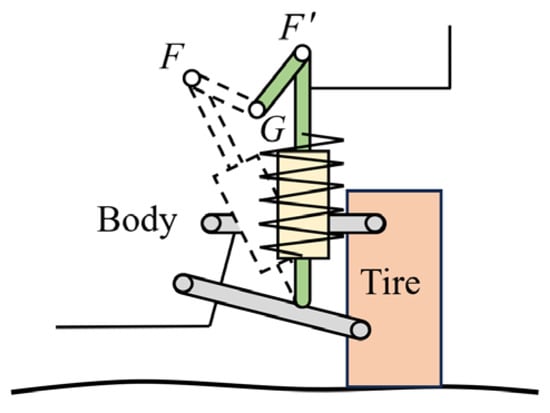
Figure 3.
Suspension structure with adjustable connection.
2.3. Inerter–Spring–Damper (ISD) Suspension
In addition to the variable structure suspension, the suspension system formed by different combinations of the two basic components of the spring and damper is also constantly being proposed, but the effect is limited. Later, people began to seek new components to change the traditional suspension structure system. In 2002, Professor Smith proposed a concept of an inerter, which completely broke the basic structure of the “spring-damper”. As a two-end point element, the inertial force of the inerter is proportional to the relative acceleration of the two ends. Thus, a new suspension, called ISD suspension, has also emerged based on ISD. Using the theory of electronic networks, the researchers make the “capacitance-inductance-resistance” electronic network system and the ISD suspension structure system strictly correspond to each other, which expands the development space of suspension technology [21,22].
Shen [23,24,25] developed a ball screw electromechanical inerter, as shown in Figure 4. An optimal design method of a mechanical ISD suspension system based on a fractional-order electrical network is proposed. The results show that the root mean square (RMS) of the vertical acceleration and the RMS of the pitch angular acceleration of the ISD suspension are reduced by 31% and 35%, respectively.

Figure 4.
Electromechanical inerter proposed by Shen [23].
Li [26,27] designed an inerter suspension, as shown in Figure 5. The model of the ISD suspension vehicle, including vertical, pitch, roll, and yaw motion, is established, and the influence of coupling excitation on the vibration reduction performance of the ISD suspension system is studied. When the excitation amplitude increases in the range of 0.02~0.04 m, the RMS value of the vehicle body acceleration of the two-stage ISD suspension system structure always maintains a high degree of improvement, and the ride comfort is improved by more than 61%. When the vehicle speed increases in the range of 10~25 m/s, the performance improvement rate can reach more than 34.1%.
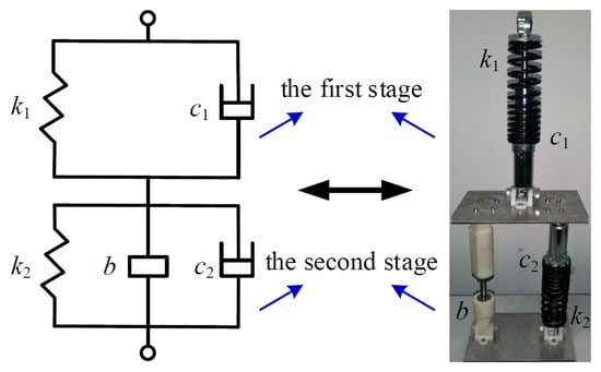
Figure 5.
The inerter suspension proposed by Li. [26].
Yang [28,29] combined the accelerated drive damping (ADD) method and the ISD passive network, using the ADD to suppress the vibration of the middle and high frequency bands and using the ISD passive network to suppress the vibration of the low frequency band to isolate the vibration of a wider frequency range in the vehicle ISD suspension system. Zhang [30,31,32] proposed a hydro-pneumatic two-stage ISD suspension combining a hydro-pneumatic spring and an inerter, which can significantly reduce the vibration of the body and wheels, and it has a smaller suspension installation space.
2.4. Summary of the Chapter
Passive suspension has become the dominant solution for current mass-produced vehicles thanks to its notable advantages, including simple topological structure, high reliability, low manufacturing cost, and zero energy consumption. In response to its diverse structural configurations, researchers often employ parameter optimization techniques (such as model-based methods or experimental design approaches) to enhance its performance. However, from a methodological standpoint, this type of optimization essentially falls into the category of static or quasi-static design. Its core limitation lies in the immutability of system characteristics (stiffness and damping)—this fixes the performance ceiling of passive suspension through physical parameters, making it difficult to effectively adapt to complex and variable time-varying operating conditions (e.g., road excitation, load changes, and dynamic maneuvers). Meanwhile, key components of passive suspension, such as the “spring-damper” connecting hardpoints and control arm bushings, have design tolerances ranging from ±0.1 mm to ±0.5 mm [33]. Excessive deviations during assembly (e.g., control arm bushing deviation exceeding 0.3 mm) can cause shifts in wheel alignment parameters, which in turn lead to handling anomalies like straight-line drift and uneven tire wear. In contrast, intelligent suspensions can automatically compensate for the aforementioned deviations and mismatches via real-time control of actuators. Therefore, conducting research and development on intelligent suspensions is crucial for breaking through the performance bottlenecks of passive suspension and represents one of the core development directions in vehicle chassis technology.
3. Semi-Active Suspension
The principle of semi-active suspension is shown in Figure 6, which is mainly composed of elastic components, sensors, semi-active actuators, and controllers, and the mathematical models of semi-active suspension are detailed in Appendix A.2. The sensor is utilized to sense the road condition and the vehicle state, the actuator is used to adjust the suspension stiffness and damping, and the controller is utilized to calculate the control strategy of the suspension system in real-time. Different from active suspension, semi-active suspension does not require high energy and only consumes a small amount of energy to adjust the control valve of the actuator, having the advantages of a simple structure, low energy consumption, and low cost. As the damping control is simpler than the stiffness control, the research of semi-active suspension mainly focuses on adjusting the damping. The adjustable damping shock absorber is used as the actuator and can be adjusted in steps, or it can be stepless.
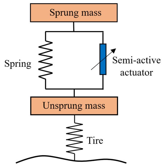
Figure 6.
Principle of semi-active suspension.
3.1. Continuous Damping Control (CDC) Damper
The concept of the CDC damper is proposed for the first time by the ZE company. The damping force of the CDC damper is adjusted by an electronically controlled valve to adapt to different road conditions and driving requirements, which can significantly improve the vehicle’s handling stability and ride comfort. CDC dampers are first mass-produced on Opel Omega and are gradually applied to high-end brand models such as BMW, Audi, and Mercedes-Benz. Recently, CDC suspension has been widely used and extended to commercial vehicles, such as trucks and buses.
Bai [34] obtained the characteristic curve of the CDC damper by establishing its hydraulic mathematical model and compared it with the experimental data. The results show that the experimental curve is basically consistent with the simulation curve, which provides a theoretical reference for the design and characteristic analysis of the CDC damper. Wang [35] developed a solenoid valve CDC damper, as shown in Figure 7, and established its basic model based on structure and performance parameters. Then, the model parameters were modified to fit the experimental data using the experimental data. This modeling method is simple and easy to implement on the controller.
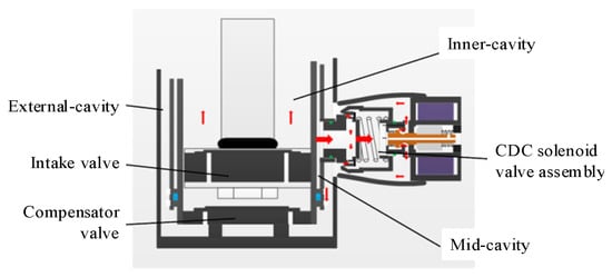
Figure 7.
CDC damper developed by Wang [35].
Xie [36] established a force mathematical model of the CDC damper based on the throttling characteristics of the damper valve. The relative error between the simulation and the experiment is less than 10%, with high accuracy. Zhang [37] proposed a new CDC suspension structure. The vertical load distribution is adjusted by changing the suspension damping force to assist the ESP. Li [38] proposed a hybrid model combining a lumped parameter model and a neural network model to accurately describe the physical characteristics of the CDC damper. Zhang [39] proposed a continuous damping control (CDC) shock absorber, obtained control variables by analyzing the dynamic performance of the semi-active suspension system coupled with the CDC shock absorber, and derived the mathematical function of the semi-active suspension. The test bench shown in Figure 8 has been built.
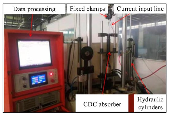
Figure 8.
Test bench of the CDC damper built by Zhang [39].
3.2. Magnetorheological (MR) Damper
MR fluid, a kind of intelligent material controlled by a magnetic field, can change its rheological properties in milliseconds. Therefore, the MR damper can achieve rapid adjustment of the damping force. General Motors applied MR dampers to the vehicle suspension system for the first time, that is, Magneride suspension, and carried out multiple technical iterations. Magneride suspension was mass-produced on the Cadillac Seville STS for the first time. After that, MR dampers have begun to be promoted to more models, such as the Chevrolet Corvette and Ferrari 458, and they are widely used in civil engineering, aerospace, and other fields. Presently, the application of MR intelligent suspension is gradually maturing and is applied to low-end vehicles [40].
Sun [41] proposed an MR semi-active suspension control system based on road information recognition and established a semi-active suspension model based on a parameterized magnetorheological damper and collected information on four typical road types, controlling the selection of current for the MR semi-active suspension according to different road types. Wei [42] proposed a semi-active suspension with a conical flow mode MR. The magnetic circuit of the proposed structure was designed, its dynamic model was established, and finite element simulation analysis was carried out, providing a new idea for improving the vehicle control stability by optimizing the MR damper. Yang [43] proposed an MR semi-active suspension system with a negative stiffness component, and the damper is shown in Figure 9. The results show that the damping performance is obviously better than that of passive suspension and traditional MR suspension and is equivalent to that of some active suspensions.
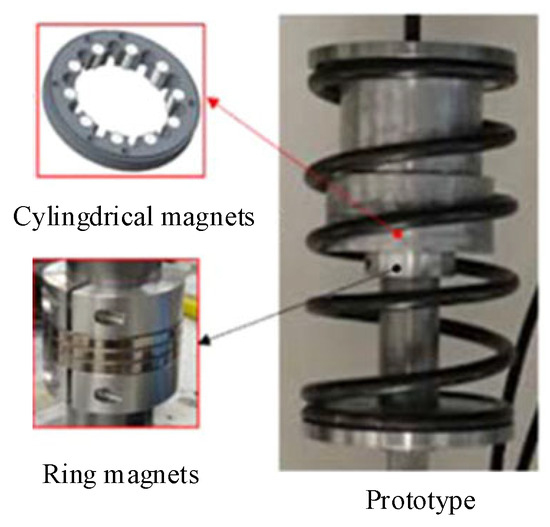
Figure 9.
MR damper developed by Yang [43].
3.3. Electrorheological (ER) Damper
Similar to MR fluid, ER fluid, a kind of intelligent fluid, can change its viscosity in milliseconds under the action of an applied electric field. Thus, an ER damper is generated to realize the rapid adjustment of the damping force. Compared with the traditional damper, the ER damper has significant advantages in vibration reduction, response speed, and energy consumption. It has been applied in the fields of automobile suspension, aerospace, and building structure vibration reduction.
Tang [44] designed an ER damper that consists of ER fluid, housing, an air accumulator, and a piston head with electrodes installed, as shown in Figure 10. The electrorheological fluid is injected into the housing, which is divided into a lower chamber and an upper chamber by the piston head. Between the bottom module and the floating piston, there is a sealed chamber filled with air, which acts as an accumulator.
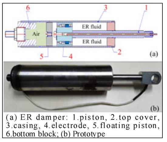
Figure 10.
ER damper designed by Tang [44].
According to the dynamic performance requirements, Sung [45,46,47] developed an ER damper and studied its force dynamic characteristics. The ER damper adopts a cylindrical structure design and can be adapted to the real-time control of the suspension. Morato [48] studied the control method of a seven-degree-of-freedom vehicle system equipped with ER damper suspension and proposed a real-time, fast, and advanced control structure in the model predictive control framework of a linear parameter varying system, achieving the coordination between ride comfort and road handling in one control cycle. Choi [49] established a Bingham model of an ER damper. On this basis, a vehicle suspension system with four independent ER dampers was constructed.
3.4. Summary of the Chapter
Research on semi-active suspensions is committed to the collaborative design of controllable dampers and real-time control strategies, with the core goal of approaching the performance of active suspensions to a large extent under the premise of strictly following the constraint of energy irreversibility, that is, only dissipating energy. The core theoretical advantage of this methodology lies in dynamically adjusting damping characteristics through algorithms to achieve the decoupling of the vibration modes of the sprung mass and unsprung mass, thereby significantly optimizing vehicle ride comfort and handling stability. However, semi-active suspensions still have inherent limitations. First, the dynamic response range and rate of the actuator constitute a fundamental bottleneck. For example, the time lag in the field-induced yield stress response of magnetorheological fluids leads to a significant deviation between the control command and the actual output force. Second, existing control laws, especially those mostly based on simplified models, generally lack robustness to the inherent nonlinear characteristics of the system (such as hysteresis effects and saturation characteristics) and complex time-varying working conditions, such as steering–braking coupling, and are highly dependent on engineering calibration. Third, their traditional energy consumption advantage faces severe challenges from the energy recovery technology of active suspensions in the electric vehicle architecture. Therefore, future breakthroughs urgently need to integrate high-bandwidth actuators, data-driven modeling, and adaptive robust control and re-examine their strategic positioning and system-level value in the intelligent chassis ecosystem.
4. Active Suspension
To further enhance vehicle dynamic performance, active suspension systems have emerged as a critical technological solution. Figure 11 illustrates the working principle of an active suspension, which consists of components such as sensors, active actuators, and controllers. Its mathematical model is detailed in Appendix A.3. Unlike semi-active suspensions, active suspensions employ actuators to adjust suspension stiffness and damping or to generate active forces with controllable magnitude and direction, thereby achieving control over body vibration and ride height [50]. It is noteworthy that although semi-active suspensions also possess adjustment capabilities, their actuators can only modify damping parameters. They lack the ability to comprehensively regulate stiffness, active forces, and vehicle height like active suspensions and thus do not offer the same comprehensive regulation capabilities. Based on control objectives and structural differences, active suspensions can be categorized into stiffness/damping adjustable types (such as air, hydraulic, and hydro-pneumatic suspensions) and geometrically adjustable types. Both types enhance vehicle dynamic performance through active adjustment, yet they differ significantly in their adjustment dimensions and applicable scenarios.
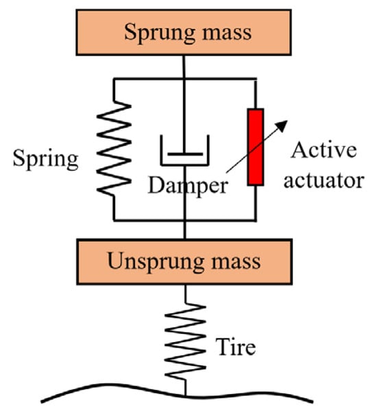
Figure 11.
Principle of active suspension.
4.1. Air Suspension
Air suspension is a typical intelligent active suspension system. Its core lies in the integration of air springs, electronic control technology, and high-performance electro-pneumatic actuators. It collects vehicle dynamics and road condition data through various sensors, transmits the data to the central controller for algorithm-based processing, and then drives valves to adjust the air pressure of the air springs. This can synchronously match the suspension stiffness and vehicle body height, ensuring driving comfort and handling stability under various road conditions. Recently, air suspension has been extending towards the fields of active safety and autonomous driving, becoming an important development direction for future automotive suspension systems.
Tan [51] studied the working characteristics of air springs and solenoid valves under different load conditions, established a mathematical model of a 1/4 air suspension system for heavy-duty commercial vehicles, and built a test bench with a double air spring structure. The test results show that this air suspension can accurately adjust the vehicle height to adapt to different load conditions. The control system is shown in Figure 12.
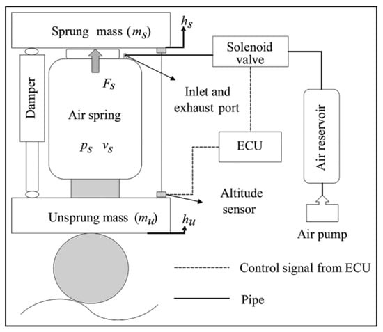
Figure 12.
Air suspension system established by Tan [51].
Long [52] conducted system identification and performance analysis of solenoid valves and air springs based on bench tests and established a refined air suspension system model. Jiang [53,54] proposed a quasi-zero stiffness air suspension system incorporating a negative stiffness mechanism, as shown in Figure 13. The quasi-zero stiffness air suspension is supported by an air spring in the vertical direction, providing positive stiffness; two horizontally opposed cylinders are installed on both sides of the air spring to provide negative stiffness. The stiffness generated by the air spring and the stiffness formed by the horizontal cylinders are added together to form the dynamic stiffness of the suspension system, enabling a smoother driving and riding experience.
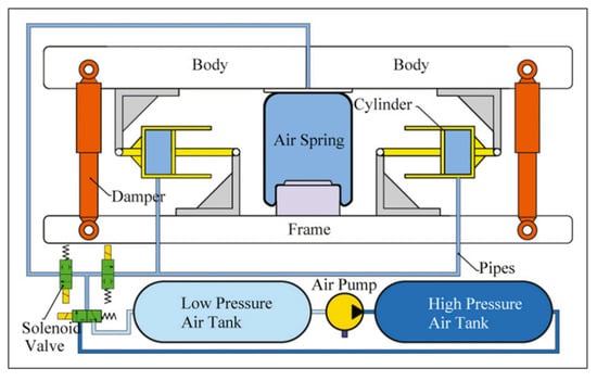
Figure 13.
Quasi-zero stiffness air suspension designed by Jiang [54].
Wang [55] designed an electronically controlled air suspension (ECAS) system to address the over-adjustment problem during vehicle height adjustment. This problem can cause the solenoid valve to open and close repeatedly due to the over-adjustment of the air suspension system during vehicle height adjustment. The control system is shown in Figure 14.
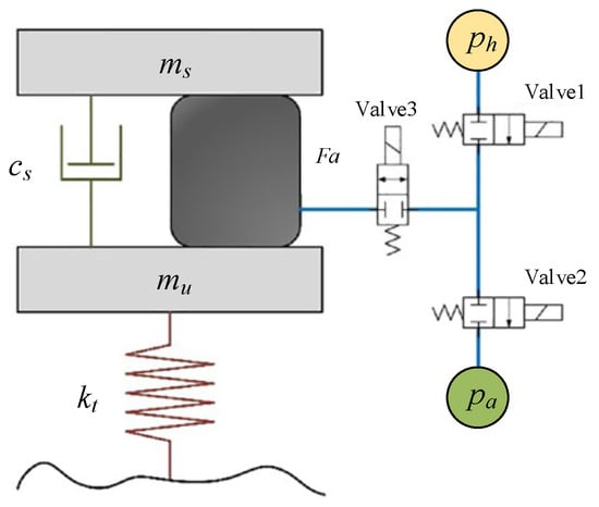
Figure 14.
Air suspension control system designed by Wang [55].
4.2. Hydraulic Suspension
For hydraulic suspensions, real-time adjustment of suspension force via an electro-hydraulic servo system is one of the effective methods, consisting of hydraulic actuators, high-speed solenoid valves, and ECUs [56]. In a hydraulic suspension system, the Electronic Control Unit (ECU), serving as the core control module, first receives vehicle attitude signals and road excitation signals collected by sensors. It then performs real-time analysis and calculation on these signals through built-in dynamic control algorithms to accurately compute the target adjustment force required by the suspension. Subsequently, the ECU generates control commands to drive the high-speed solenoid valve, which regulates the flow rate and pressure of the hydraulic circuit, thereby controlling the hydraulic cylinder to output precise hydraulic pressure that matches the target force. It has technical advantages such as high power density, wide dynamic coverage, and extreme adaptability.
Liu [57,58] established a nonlinear vehicle active suspension dynamics model, taking into account the physical characteristics of the electro-hydraulic actuator. This is not only beneficial to the precise control of the vehicle’s active suspension system but also conducive to future practical applications and the improvement of vehicle performance. Liu [59] designed a new type of energy-regenerative hydraulic interconnected suspension (ER-HIS). The design diagram of ER-HIS is shown in Figure 15. By switching the working position of the electromagnetic directional valve, the automatic switching of the vehicle body’s roll mode, pitch mode, and bounce mode is realized. The simulation results show that compared with the existing energy-regenerative hydraulic interconnected suspensions, ER-HIS has higher regenerative power and energy recovery efficiency and also exhibits excellent anti-roll and anti-pitch performance.
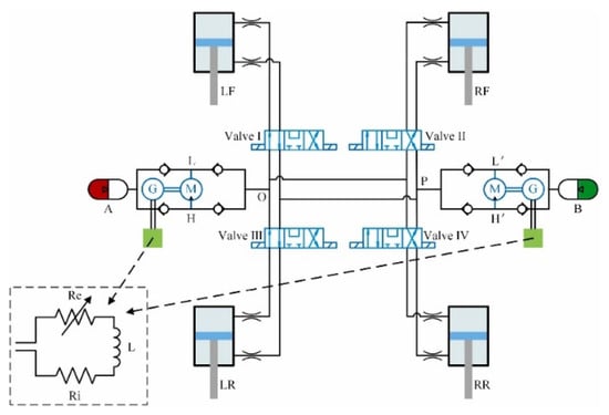
Figure 15.
ER-HIS design diagram [59].
Choi [60] established a four-degree-of-freedom hydraulic suspension system model, as shown in Figure 16, and designed a nonlinear state estimator for this four-degree-of-freedom hydraulic suspension system, ensuring the robustness of the hydraulic suspension against external disturbances.
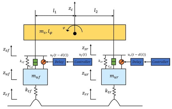
Figure 16.
Hydraulic suspension model established by Choi [60].
4.3. Hydro-Pneumatic Suspension
Hydro-pneumatic suspension achieves dynamic suspension force control through an oil–air coupling medium and an electronic control system. The core consists of an oil and gas spring (including a high-pressure nitrogen chamber), a proportional servo valve, and a multi-mode controller. Hydro-pneumatic suspension utilizes gas compressibility to absorb impact and dynamically changes equivalent stiffness and damping by adjusting oil pressure, and has the advantages of strong environmental adaptability, high energy density, and multi-degree-of-freedom regulation.
Li [61,62] developed a compact dual-chamber hydro-pneumatic strut active suspension based on motor drive, as shown in Figure 17. Under different operating conditions, the RMS improvement rate of the roll angle and pitch angle exceeds 50.46%.
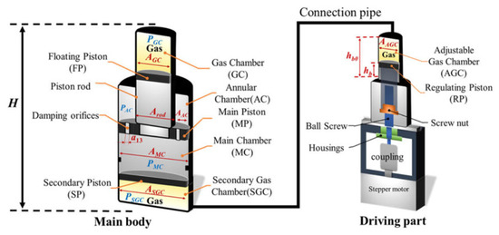
Figure 17.
Hydro-pneumatic suspension developed by Li [61].
Jiang [63,64] introduced MR damping technology into single-chamber hydro-pneumatic springs to address the problem of real-time adjustment of damping coefficients in traditional hydro-pneumatic springs. A shear valve mode MR hydro-pneumatic spring is proposed and analyzed based on multi-physics coupling simulation and mechanical performance testing. Yin [65] developed a hydro-pneumatic suspension based on high-speed switching valves, which has two spring force modes and four damping force modes. Based on the parameters of the mining truck, the stiffness coefficient and damping coefficient of the hydro-pneumatic suspension were optimized, as well as the initial inflation pressure of the accumulator and the diameter of the throttle valve. Wu [66,67] designed a six-arm suspension wheel leg device based on hydro-pneumatic springs to solve the problem of inconsistent elongation length of hydro-pneumatic springs during horizontal steering. Wang [68] proposed a magnetorheological hydro-pneumatic suspension system, embedding a piezoelectric energy harvester into the hydro-pneumatic suspension, which simplified the suspension structure and achieved a self-powered effect. Chen [69] introduced a new breakthrough in the structural design of hydro-pneumatic suspensions by integrating a piezoelectric energy harvester into the suspension, thereby developing a self-powered hydro-pneumatic suspension system. The core purpose is to reduce energy consumption during the operation of the system. Subsequent numerical simulation studies have confirmed that this hydro-pneumatic suspension equipped with a piezoelectric energy harvester can fully achieve self-powered operation.
4.4. Active Variable Geometry Suspension
Active variable geometry suspension dynamically optimizes wheel alignment parameters (such as camber and toe angles) by real-time adjustment of the suspension linkage geometry [9]. Its core components include electronically controlled actuators, multi-link mechanisms, high-precision position sensors, and a central controller. By actively regulating hardpoint positions, the system modifies tire contact characteristics and roll center height, significantly enhancing vehicle handling stability and road adaptability, with particularly outstanding performance in high-speed cornering and asymmetric road conditions.
Yu [70] introduced a series-configured active single-link mechanism between the spring–damper unit and the vehicle body, establishing a unique geometrically variable actuation system. Driven in real-time by an electro-mechanical actuator, the single-link rotates to actively adjust the suspension hardpoint positions and instantaneous kinematic relationships, thereby directly optimizing tire–ground contact characteristics and vertical force distribution. Chen [71] demonstrated a novel concept of series active variable geometry suspension applicable to road vehicles. They took into account the coupled response of the four independently driven suspension corners of the vehicle and proposed an accurate dynamic and geometric model. Arana [72,73,74] proposed the Series Active Variable Geometry Suspension (SAVGS), as shown in Figure 18. This suspension design adds a motor-driven linkage mechanism between one end of the traditional spring–damper unit and the vehicle body. It changes the linkage’s angle to dynamically adjust the installation position and attitude of the spring–damper, and in this way achieves active variability of suspension geometry.
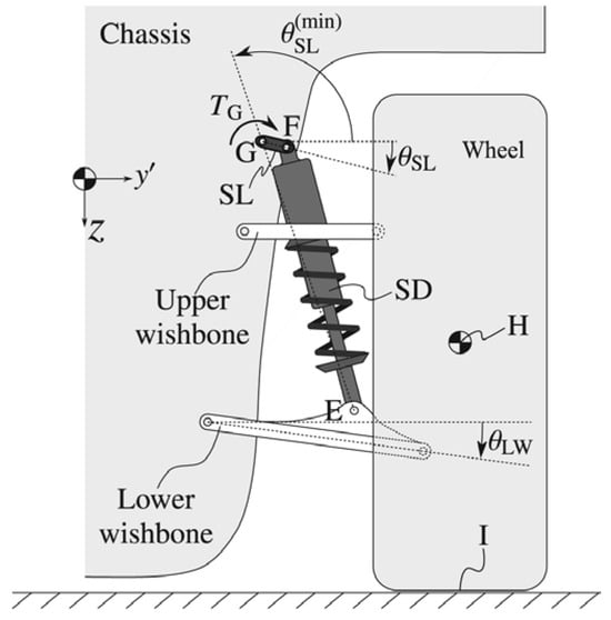
Figure 18.
Schematic diagram of SAVGS by Arana [74].
4.5. Summary of the Chapter
Research on active suspensions focuses on the integrated design of high-dynamic-response actuators, advanced control laws, and real-time energy management. Its core advantage lies in full-frequency domain force control, which can break through passive constraints and independently optimize ride comfort, handling stability, and attitude control. However, active suspensions still face multiple challenges. First, the increased system complexity and cost (high-power power supplies/pump stations, precision sensor networks, redundant safety designs) severely restrict the feasibility of mass production. Second, the inherent performance–energy consumption paradox—the pursuit of high-frequency response and large force output—is inevitably accompanied by a huge energy consumption burden. Even with electromagnetic schemes using energy recovery, the net efficiency of the system remains uncertain. Third, the robustness of control laws is highly dependent on accurate system models. When faced with strong nonlinear characteristics and actuator saturation/bandwidth limitations, control performance tends to deteriorate, and complex algorithms increase the burden of real-time computation. Future breakthroughs urgently require the development of high-power-density/high-efficiency actuators, the advancement of model–data fusion robust control architectures, and deep integration into the vehicle’s energy flow optimization strategies to reconcile its excellent performance potential with practical engineering constraints.
5. Electromagnetic Suspension
According to the actuator structure, electromagnetic suspension can be divided into rotary motor electromagnetic suspension and linear motor electromagnetic suspension. Electromagnetic suspension has attracted widespread attention from researchers due to its dual functions of energy regeneration and active control.
5.1. Rotary Motor Electromagnetic Suspension
Zhao [75] developed a ball screw rotary electromagnetic suspension, as shown in Figure 19. The actuator adopts a dual-damping structure to solve the problem of large equivalent inertia mass.
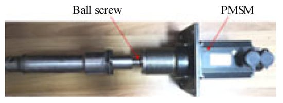
Figure 19.
Ball screw electromagnetic actuator designed by Zhao [75].
Zhang [76] proposed a new type of energy-regenerative ball screw rotary motor suspension to improve the damping performance of the suspension, as shown in Figure 20. The ball screw type energy-regenerative actuator consists of an energy-regenerative motor and a ball screw mechanism, which can recover energy while reducing vibration.
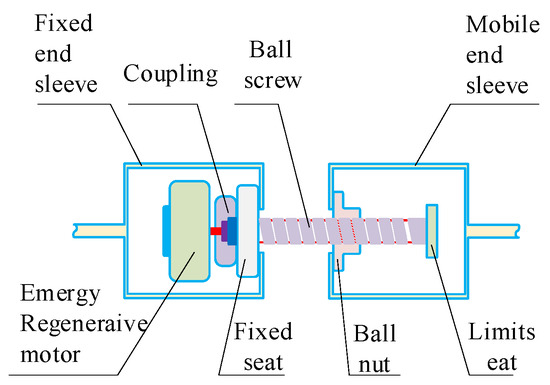
Figure 20.
Electromagnetic actuator designed by Zhang [76].
Ge [77] proposed an electromagnetic suspension system using a planetary flywheel ball screw mechanism and a permanent magnet synchronous motor and studied the effects of ball screw nut friction, transmission clearance, planetary gear friction, and gear clearance on suspension performance, providing technical reference for the design of planetary flywheel ball screw electromagnetic suspension. Kavianipour [78] proposed a permanent magnet DC motor electromagnetic damper and analyzed the suspension damping performance and energy recovery performance.
5.2. Linear Motor Electromagnetic Suspension
Unlike rotary motor electromagnetic suspension, linear motor electromagnetic suspension does not require an intermediate transmission mechanism. Therefore, the structure of linear motor electromagnetic suspension is simpler. Linear motors have a similar external structure to traditional passive dampers, consisting of a rotor and a stator. The rotor is equivalent to the piston rod of the damper and is connected to the vehicle’s body, while the stator is equivalent to the cylinder of the damper and is connected to the wheels. During the suspension movement, the linear motor electromagnetic suspension can output power to suppress vehicle vibration and can also convert mechanical vibration energy into electrical energy [79].
Sun [80,81] constructed a suspension structure where a spring, a damper, and a linear motor are installed in parallel. The vibration reduction performance of the active suspension of this structure is comparable to that of an ideal active suspension, but it has the characteristics of low energy consumption and high reliability. Li [82] proposed a new method involving the recovery of vibration energy from suspensions and wheels and designed a new structure integrating Linear Electromagnetic Shock Absorbers (LEMDs) and Linear Electromagnetic Dynamic Vibration Absorbers (LWM-DVWs), which balances the vibration energy recovery and dynamic performance of electric vehicles. Xiong [83] proposed a unique linear motor energy recovery suspension system using a Halbach-like permanent magnet array, which increased the probability density of the generator. Compared with passive suspensions, this suspension system also reduced the vertical vibration of the vehicle body by 14.66% and improved the ride comfort, safety, and maneuverability of the vehicle. Liu [84] adopted a track coil arrangement scheme and a hollow motor structure to reduce the manufacturing cost and improve the motor thrust performance. Ding [85,86,87] designed a hybrid electromagnetic suspension actuator to reduce energy consumption and improve the reliability of linear motor electromagnetic active suspension, as shown in Figure 21, and passive damping is utilized to address the shortcomings of active control.
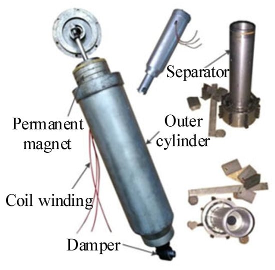
Figure 21.
Hybrid electromagnetic actuator developed by Ding [85].
5.3. Summary of the Chapter
As a new generation of active suspension technology, electromagnetic suspension’s core advantage lies in achieving millisecond-level damping adjustment through electromagnetic actuators. Combined with algorithms, such as model predictive control (MPC), it can dynamically optimize vehicle body posture, representing a significant theoretical breakthrough in balancing handling and ride comfort. Methodologically, a multi-dimensional evaluation is required. At the dynamic level, its robustness under random road conditions and extreme working conditions needs verification; at the energy level, the contradiction between active control energy consumption and energy recovery efficiency must be quantified; and at the engineering level, constraints on mass production feasibility, such as the risk of electromagnet demagnetization and the cost of power devices, should be considered. Critically, current technical bottlenecks exist. First, high-cost electromagnets and precision sensors rely on imports, with the reliability of domestic alternatives yet to be verified; second, control algorithms are prone to model mismatch under complex working conditions, leading to gaps between actual performance and simulations; and third, hysteresis effects in low-temperature environments cause response delays, resulting in insufficient adaptability to extreme road conditions. Future breakthroughs should focus on integrating low-cost magnetic circuit design with adaptive control algorithms.
6. Control Method of Intelligent Suspension
The key to intelligent suspension lies in two aspects: one is the actuator structure; the other is the control method. The two complement each other and jointly determine the comprehensive control performance of intelligent suspension. To further improve the performance of the intelligent suspension system, it is necessary to not only innovate the actuator structure but also develop the control method with outstanding performance.
6.1. Classical Control Strategy
The classical control theory mainly depends on the methods of frequency domain analysis or time domain analysis, which are usually suitable for linear time-invariant systems and have limited processing ability for nonlinear systems or time-varying systems. Presently, classical control strategies commonly include skyhook control [88] and PID control [89,90].
6.1.1. Skyhook Control
Skyhook control proposed by Karnopp has become a classic algorithm in intelligent suspension control. As shown in Figure 22, the skyhook algorithm assumes that there is a damping between the car body and the cloud, which is used to attenuate the vibration of the car body and improve comfort. Combined with the actual suspension system, it takes a damping close to this assumption. However, the skyhook control does not solve the problem of vehicle handling and stability. Similar to skyhook control, groundhook control assumes a reference ground, and a damping system is added between the reference ground and the unsprung mass so as to reduce the vertical vibration of the wheel and improve handling stability. As the performance of skyhook and groundhook control is relatively single, many modified skyhook and groundhook control methods have been proposed.
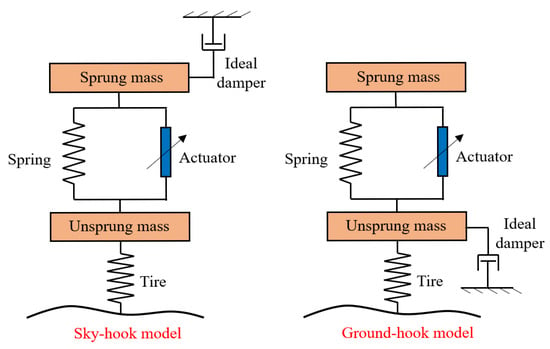
Figure 22.
Ideal skyhook and groundhook.
Jiang [91] used the hybrid damping control method of combining a skyhook and groundhook to improve the ride comfort and road holding of MR semi-active suspension vehicles and optimized the coefficient with a genetic algorithm. Kou [92] proposed a multimodal endocrine compound skyhook and groundhook control strategy for hybrid electromagnetic suspension, combining endocrine control with long feedback and short feedback with a skyhook and groundhook. Zajac [93] proposed a modified continuous skyhook control strategy considering nonlinear stiffness characteristics to improve the body stability and ride comfort of tracked military vehicles. Ma [94] designed a fuzzy canopy controller based on the gray wolf optimization algorithm. The method can simultaneously reduce the amplitude of vertical acceleration, suspension deflection, and tire dynamic load. Negash [95] used skyhook and hybrid skyhook acceleration-driven damper control algorithms to control the semi-active suspension train. The ride comfort of the two controllers is improved by 54.49% and 58.49%, respectively. Wang [96] proposed a vehicle vibration suppression strategy by integrating a skyhook and active disturbance rejection control, which makes the vehicle have good damping capacity on random roads, convex roads, and sinusoidal roads. Zhang [97] adopted three different skyhook control strategies, namely, independent control, inertia-based control, and damping-based control, to achieve the control of road holding without sacrificing ride comfort. Lu [98,99] proposed a coordinated suspension control method with an integrated skyhook–LQR to improve the vehicle’s vertical, pitch, and roll motion attitude. The algorithm of this method is simple and easy to implement on the vehicle-level microcontroller.
6.1.2. PID Control
PID control is widely used in intelligent suspension systems because it is simple, has high reliability, and is easy to implement. This algorithm includes three main parts, the proportional term, the integral term, and the differential term, each of which has a unique contribution to the control effect. The control principle is shown in Figure 23.
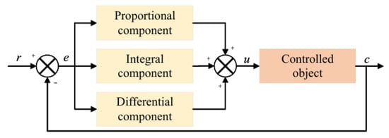
Figure 23.
PID control principle.
Zhao [100] proposed a cuckoo search optimization PID control strategy, which uses the cuckoo algorithm to optimize the three control gain parameters of the PID and calculates the required damping force from the PID to improve the ride comfort of the vehicle. Talib [101,102] used the intelligent optimizer of the advanced firefly algorithm to obtain the control parameters of the PID control of the semi-active suspension system. The vehicle comfort performance under this method is better than other traditional algorithms. Li [103] proposed a control strategy for automotive semi-active suspension based on fractional order PID, which combines fractional order theory with traditional PID control to improve the controllable range and accuracy. Zhang [104] combined a genetic algorithm with fuzzy PID control and used a genetic algorithm to optimize the setting process of fuzzy PID parameters. Cao [105] designed a PID controller for a transversely interconnected electronically controlled air suspension system based on a seeker optimization algorithm. The group search algorithm was used to optimize the PID control parameters, which effectively improved the ride comfort and running stability of the vehicle. Munawwarah [106] designed a comprehensive control strategy of PID-LQR and fuzzy PID based on the half-car model, which maximized driving comfort while ensuring good road holding. Samaroo [107] proposed a semi-active suspension system for hub-motor vehicles, which combined a dynamic vibration absorption structure and a PID-controlled MR damper.
6.2. Modern Control Strategy
Classical control is simple in structure and easy to implement, but it has some shortcomings, such as limited optimization performance and difficulty in improving ride comfort and wheel grounding at the same time. Therefore, a modern control strategy is applied to the suspension control. The common modern control methods include adaptive control, optimal control, and so on. These methods can better deal with the nonlinearity, uncertainty, and complexity of the system [108,109,110,111].
6.2.1. Adaptive Control
Adaptive control is a control method for uncertain systems. As the parameters of the vehicle always change randomly to form a nonlinear system in the process of driving, adaptive control can take into account the characteristics of the control object and disturbance and give an appropriate control law to make a performance index reach the optimal value.
Yao [112] designed an adaptive controller with time delay compensation to solve the problem of low controller accuracy of nonlinear suspension. Compared with no time delay compensation, the vertical acceleration of the sprung mass is significantly reduced. This method can deal with the problems of variable time delay, nonlinear vibration, and predictive control. Mousavi [113] developed a tube-based model reference adaptive control method for a multi-input and multi-output active suspension system, which has good ride comfort and handling stability on concave and convex roads, random roads, and sinusoidal roads. Nichielea [114] proposed an adaptive harmonic control method based on the harmonic control signal with variable amplitude and frequency generated by body acceleration. Compared with other existing control methods, it requires less feedback data and has outstanding control performance. Deng [115] used the event trigger mechanism in the channels from sensor to controller and from controller to actuator and proposed an adaptive fuzzy optimal suspension control method based on event trigger. Guo [116] studied a nonlinear adaptive fault-tolerant control method, which can accommodate multiple actuator faults without expensive fault detection and isolation mechanisms. Li [117] proposed an adaptive fuzzy output feedback fault-tolerant control method to improve the reliability of the electromagnetic active suspension system. Aela [118] proposed a method of combining an adaptive radial basis function neural network with backstepping control to overcome dynamic phenomena such as nonlinearity, parameter uncertainty, and rigid external disturbance. Zheng [119] studied the adaptive backstepping control of a cloud-aided nonlinear active vehicle suspension system and proposed an adaptive control strategy to update the controller in the remote cloud. Compared with the passive suspension system, the performance of the controller is improved by more than 80%.
6.2.2. Optimal Control
Optimal control is used to design a controller according to the object studied so that the performance index of the controlled object can reach the optimal value. Its main steps are to establish the system state equation, determine the objective function, and solve the optimal feedback equation. LQR is a widely used optimal algorithm.
Uddin [120] proposed an LQR optimal control strategy for a vehicle active suspension system. LQR was used to transform the control design problem into the optimization of minimizing the quadratic cost function, and the optimal state feedback control was obtained. Bai [121] designed a robust optimal control strategy by combining LQR with SMC for the uncertainty of the suspension system and external random interference. Liang [122] established the nonlinear mechanical model of the tracked vehicle suspension system and designed the optimal control method of the active suspension, which effectively improved ride comfort. Gu [123] proposed an optimal polynomial control strategy based on dynamic programming, which reflected the sprung mass acceleration and suspension deflection in the performance index and derived the optimal nonlinear polynomial suspension control force by selecting the cost function in polynomial form. Min [124] used the fuzzy logic system to learn the unknown nonlinear dynamic characteristics and proposed a fuzzy adaptive optimal control scheme to ensure the stable control of the active suspension on the vertical vibration. Manna [125] designed a vehicle state feedback controller to solve the problem that the multi-objective weights of LQR are difficult to optimize, using the ant colony algorithm to find the optimal LQR weight coefficient matrix. Ahn [126] designed an LQG optimal control algorithm for the semi-active suspension of the hydraulic-pneumatic mechanism of an agricultural vehicle. The motion state information, such as suspension deflection, is estimated using Kalman filter state observer, and the control force is solved by optimal control.
6.2.3. Robust Control
Robust control can ensure that the system remains stable under bounded disturbance, and the H∞ control method is a typical design method. In addition, as a variable structure control method, SMC can easily ensure the stability of the system and has good robustness, but it is prone to chattering.
Nguygn [127,128] designed an SMC algorithm for active suspension. Compared with passive suspension, the displacement and acceleration of the sprung mass are significantly reduced by 14.4% and 14.1%, respectively. Sun [129] proposed a semi-active control strategy for automotive interconnected air suspension considering parameter uncertainty. The control strategy can not only improve suspension performance; it also has strong robustness to parameter uncertainty. Ozbek [130,131,132] proposed a model-based robust control law to enhance vehicle ride comfort and applied it to a 7-DOF vehicle suspension system with friction nonlinearity. Yin [133] considered the actual parameter uncertainty, structural uncertainty, and time delay of the actuator, designed a robust control strategy, and verified the performance under random road and deceleration belt road. Ma [134] established the H2/H∞ multi-objective performance index and proposed a multi-objective non-fragile H∞ control algorithm based on the effective Lyapunov functional to improve ride comfort and ensure the system constraints. Afshar [135] proposed a multi-objective dynamic output feedback robust H2/H∞ controller for the inerter active suspension system with parameter uncertainty and external interference, which comprehensively improved ride comfort, handling stability, and suspension deflection.
6.3. Intelligent Control Strategy
With the development of science and technology, intelligent algorithms have been widely used in the engineering field [136,137,138]. The emergence of intelligent control is used to solve the control problems of complex systems, and it is difficult to establish accurate mathematical models. Intelligent control uses artificial intelligence technology, such as fuzzy logic [139,140,141], neural networks [142,143,144], genetic algorithms [145,146], and machine learning [147,148,149], to realize adaptive, self-organizing, and self-learning control. In the suspension control, intelligent control can automatically adjust the control parameters according to the road conditions through learning.
6.3.1. Fuzzy Control
Fuzzy control is an intelligent control strategy that reasonably designs fuzzy rules to achieve control. It mainly includes fuzzification, rule base, fuzzy reasoning, and defuzzification. The control principle is shown in Figure 24. Fuzzy control does not need to specify the mathematical model of the object. It has strong robustness and high disturbance ability and can meet the needs of complex tasks. Additionally, most researchers integrate fuzzy control with other algorithms to further improve the control performance of the algorithm. Its disadvantage is that the establishment of a fuzzy rule base depends on expert experience and lacks construction standards.

Figure 24.
Fuzzy control principle.
Ji [150] designed a variable domain Takagi–Sugeno fuzzy controller and proposed a CDC semi-active suspension control strategy based on a deep neuro fuzzy system to solve the problem that the traditional fuzzy controller relies on expert experience in the rule base. Jia [151] established a Takagi–Sugeno fuzzy suspension model with nonlinear components using the local linear regression method and proposed an adaptive fuzzy event triggering control method, which effectively improved the performance of the suspension system under the limit constraints of suspension deflection and tire deformation. Wong [152] proposed adaptive event-triggered dynamic output feedback control based on an interval type 2 fuzzy method, improving suspension performance and saving network resources simultaneously. Li [153] proposed an asynchronous fuzzy output feedback control method for sampled data and an optimal solution iteration algorithm. The effectiveness of the proposed controller was verified by numerical simulation. Mustafa [154] proposed an adaptive fuzzy control method based on time delay for a nonlinear automotive active suspension system, which is simple in structure and easy to adjust. Ren [155,156] proposed a fuzzy controller based on homogeneous polynomial parameter correlation technology, which greatly improved the flexibility of the fuzzy controller. Abut [157] designed a fuzzy LQR control algorithm for active suspension. The control performance in terms of body motion, body acceleration, suspension deflection, and tire deflection has been improved by more than 84.2% compared with the existing research.
6.3.2. Neural Network Control
The neural network control (NNC) is a control algorithm that models the human brain according to the information processing mode of the human brain. Each neuron can calculate and make decisions independently, making the algorithm have good adaptability and fault tolerance.
Mustafa [158] proposed a nonlinear vehicle active suspension control strategy based on the combination of time delay control and adaptive neural network control, which has significantly better performance than the traditional passive suspension and time delay PID controller. Ghoniem [159] used an artificial neural network (ANN) controller to control the throttle valve of semi-active suspension, using PID control to obtain control data under different working conditions for neural network training. Aiming at the key engineering problems, such as energy efficiency, input delay, and unknown/uncertain in active suspension systems, Zhang [160] proposed a biological nonlinear dynamics adaptive neural network control method, which used a neural network to approximate uncertain/unknown dynamics. It can not only update the input and output weights of the neural network online but also intentionally introduce beneficial nonlinear dynamics into vibration control. Hamza [161] established the mathematical model of the truck hydraulic active suspension system and designed the artificial neural network nonlinear active suspension controller. Homayoun [162] proposed a radial basis function neural network minimum learning backstepping control method to deal with the random disturbance of the nonlinear active suspension system and the saturation of the hydraulic actuator. Wang [163] proposed an observer-based neural network output feedback control algorithm to improve vehicle ride comfort by constructing an auxiliary system to compensate for input saturation constraints.
6.3.3. Composite Control Algorithm
Moreover, global optimization probability algorithms, such as the genetic algorithm and the particle swarm optimization algorithm, are widely used in the field of vehicle control due to their wide application range, strong robustness, and simple thinking [164,165,166]. Du [167] proposed an adaptive skyhook control method based on a modified genetic algorithm for road impact caused by different driving speeds. In this method, the vibration dose value of the floor vertical acceleration at the driver’s position is selected as the objective function of the genetic algorithm to obtain the optimal skyhook coefficient. Pedro [168] established the particle swarm optimization objective function based on ride comfort, road holding, suspension deflection, and power consumption and proposed a particle swarm optimization model predictive controller for a nonlinear electro-hydraulic suspension system.
Recently, with the improvement of chip computing power and the decline of hardware cost, an intelligent control method based on deep learning has been widely used in vehicle suspension control. Reinforcement learning algorithms, mainly including Q-learning, deep Q-networks, and deep deterministic strategy gradient algorithms, are constantly proposed. The high-dimensional fitting ability of intelligent algorithms replaces mathematical modeling and solves complex control problems through end-to-end learning [169,170,171]. Wiberg [172,173] adopted technical training strategies such as domain randomization, action delay, reward, and punishment to realize the engineering application of a deep reinforcement learning controller in a heavy vehicle active suspension system through multi-body dynamics and system identification and successfully narrowed the gap between simulation and reality. Deng [174] developed an active suspension system framework based on a dual-delay depth deterministic strategy gradient (TD3) and proposed an enhanced TD3 algorithm containing physical security constraints. Ming [175] used the modified deep deterministic policy gradient algorithm to control the semi-active suspension, considering the continuity of the state space and executive action. Lee [176] proposed a near-optimal semi-active suspension ride comfort controller based on the theory of deep reinforcement learning to enhance the convergence of the training process. Ahmad [177] proposed an active suspension control algorithm based on reinforcement learning. Compared with other controllers, such as LQR, the full state feedback controller, and the PID controller, the comprehensive dynamic performance has been improved.
With the rapid development of high-order intelligent driving, the driving environment recognition technology under a multi-sensor scheme is becoming mature, which provides technical support for intelligent suspension control based on road information. Scholars began to take road recognition as the discrimination condition and switched the suspension working mode and control parameters according to real-time road conditions.
Common road recognition technologies can be divided into the following three categories: direct measurement, non-contact measurement, and reverse recognition based on system dynamic response. The direct measurement method is to use the road roughness meter installed or connected to the vehicle to measure the road profile by keeping contact with the ground all the time [178,179]. The non-contact measurement method measures the road roughness information through the distance sensor (such as laser sensor, ultrasonic sensor, and infrared sensor) or visual sensor (camera) installed on the vehicle [180,181]. The reverse recognition method based on system dynamic response uses vehicle dynamic response information to estimate road roughness, which can reduce environmental sensitivity and estimation cost [182,183].
Liu [184,185] proposed a semi-active suspension switching control strategy based on road information estimation to effectively improve the dynamic performance. The road disturbance is estimated using the transmission characteristics of the suspension system to realize the online estimation of road roughness. A switching controller with multiple sub-controllers is designed to realize the automatic switching of the controller under different road conditions. Kaldas [186] modified the model reference controller through road preview, and the driving performance of the vehicle was improved. Zhu [187] proposed a road roughness estimation method based on Kalman filtering, which uses a integrated input state estimation method to recognize the road profile for intelligent suspension. Kim [188,189] proposed an adaptive discrete Kalman filter for simultaneously estimating all state variables and unknown road roughness.
Furthermore, it can be seen from the above research that due to the limited performance of a single control algorithm, composite algorithms, such as fuzzy SMC and fuzzy PID, having multiple advantages, have received attention from researchers [190,191,192]. The control strategy of intelligent suspension is constantly deepening and innovating, and algorithms with lower hardware requirements and stronger performance are preferred as the control strategy in engineering applications.
6.4. Comparative Analysis of Control Strategies
The control strategy of the automotive suspension system has a crucial impact on driving performance and ride comfort. Different suspension control strategies have distinct characteristics, advantages, and limitations. Table 1 provides a generalized analysis of the advantages and disadvantages of common control strategies for intelligent suspensions, providing a technical reference for suspension control strategy design.

Table 1.
Advantages and disadvantages of various control strategies.
6.5. Summary of the Chapter
Research on suspension control algorithms covers paradigms such as classical control, modern control, and intelligent control. The core of its methodology lies in establishing system models and designing feedback/feedforward strategies to optimize core performance indicators such as ride comfort, handling stability, and dynamic load. Classical methods have a simple structure and are easy to implement in engineering, but their ability to handle multi-objective optimization and time-varying nonlinearity is limited. Modern control, based on a rigorous mathematical framework, has excellent robustness and multi-objective coordination; however, its performance is highly dependent on model accuracy, and complex algorithms (such as nonlinear model predictive control) face significant real-time computational burdens. Intelligent control shows significant potential in dealing with strong nonlinearity, uncertainty, and adaptive learning, but it inherently has limitations such as “black-box” characteristics, poor interpretability, excessive reliance on massive data for generalization ability, and issues with training stability. However, a critical review reveals that existing research often falls into the tension between “algorithm complexity” and “engineering applicability”. It overly relies on idealized simulation verification while neglecting complex working conditions in real-vehicle environments (such as multi-body dynamics coupling, actuator hysteresis effects, and sensor noise interference) and seriously lacks consideration of engineering constraints such as long-term robustness, cost-effectiveness, and maintainability required for algorithms in mass-produced systems. Future breakthroughs need to integrate prior knowledge of physical models with data-driven learning (such as hybrid MPC reinforcement learning), develop lightweight adaptive architectures, and strengthen collaborative design oriented to engineering constraints.
7. Challenges and Development Trends Faced by Intelligent Suspension
7.1. Main Challenges
The development of intelligent suspension systems (including both active and semi-active types) is critical for advancing automotive wire-controlled chassis, as they significantly enhance driving comfort and handling. However, their widespread application and performance improvement are hindered by several technical challenges, which need to be addressed in future research. These challenges span both active and semi-active systems, as outlined below as follows:
- (1)
- Research on the deformation and dynamic stiffness characteristics of active air intelligent suspensions under multi-directional loads remains insufficient, and the relevant theoretical frameworks and calculation methods need to be improved. Existing studies lack a comprehensive theoretical description of the non-proportional deformation mechanisms (such as bending–torsion coupling effects) of air springs under multi-directional composite loads. The dynamic stiffness model ignores the time-varying coupling between the gas adiabatic process and the viscoelasticity of the air spring bladder. A more fundamental flaw is that fatigue life prediction relies on empirical S-N curves, while the cross-scale correlation model between micro-damage accumulation and macro-crack propagation is absent. This leads to large discrepancies in the life prediction of heterogeneous structure springs under accelerated aging conditions.
- (2)
- Active hydraulic intelligent suspensions rely on continuous pressurization systems and suffer from low energy efficiency. In addition, sealing issues and potential hose damage pose risks. Oil leakage not only reduces performance but also causes environmental pollution. These problems limit their practical application in energy-sensitive vehicles.
- (3)
- Some high-performance active intelligent suspensions, which are common in complex active systems, have overly complex overall structures. High-performance active suspensions fall into a negative feedback loop between actuator redundancy and mass, resulting in increased volume and mass, thereby complicating vehicle integration. Furthermore, active control modes often consume a large amount of engine power or battery energy, conflicting with the automotive industry’s demand for energy conservation. To solve these problems, breakthroughs in structural optimization and energy management are required.
- (4)
- Semi-active suspensions (such as magnetorheological and electrorheological types) face unique problems. Their damping adjustment accuracy is highly sensitive to environmental factors, such as temperature and operating frequency, which may lead to performance degradation during long-term use. The temperature coefficient of the yield stress of magnetorheological fluids far exceeds the compensation capacity of the controller, and the annual performance attenuation can reach more than 15% in high-temperature and high-humidity environments. In addition, the response speed of semi-active actuators (such as MR valves) may sometimes lag. Improving material stability and enhancing the robustness of control algorithms are crucial to overcoming these limitations.
7.2. Development Trends
Building on the challenges outlined above, the development of intelligent suspension systems will focus on targeted solutions to enhance performance, reliability, and practicality. Key trends include the following:
- (1)
- Integration and lightweight design. To address the complexity and bulk of active systems, future research will prioritize integrated structural design, reducing volume and mass through advanced materials (e.g., high-strength composites) and modular architectures. This will facilitate vehicle layout and reduce unsprung mass, improving overall dynamic performance.
- (2)
- Intelligent and adaptive control. To overcome the limitations of semi-active response speed and active system energy inefficiency, control strategies will leverage machine learning and artificial intelligence. Suspensions will autonomously identify driving conditions (e.g., road roughness, vehicle speed) and adjust parameters in real-time, balancing comfort and handling. For semi-active systems, this includes optimizing algorithms to compensate for environmental interference, while active systems will adopt predictive control to reduce energy waste.
- (3)
- Energy recovery and sustainability. Targeting the high energy consumption of active systems and pollution risks of hydraulic systems, energy recovery technologies (e.g., regenerative dampers) will be integrated to convert vibration energy into usable electricity. For hydraulic systems, eco-friendly lubricants and enhanced sealing technologies will minimize leakage and environmental impact.
Intelligent suspension, as a core component of wire-controlled chassis, will continue to evolve through synergies between structural innovation and intelligent control. By addressing the challenges specific to active and semi-active systems, it will gradually achieve wider application, offering superior driving experiences while meeting sustainability demands.
8. Conclusions
Presently, intelligent suspension has become a major research field in automobile chassis and will become a standard configuration of automobiles. This paper comprehensively summarizes the development and control status of intelligent suspension from five aspects, new passive suspension, semi-active suspension, active suspension, electromagnetic suspension, and control strategies, and it deeply discusses the main challenges and development trends faced by intelligent suspension. In the future, intelligent suspension will pay more attention to intellectualization, energy conservation, and lightweight. More new suspension systems and high-performance control algorithms will emerge. The emergence of new technologies will not only promote the progress of intelligent suspension technology but also drive the modernization process of the automobile industry.
Funding
This research was supported by the National Key Research and Development Program of China (2023YFB2504500), the National Natural Science Foundation Project of China (52472410), and the Project of College of Agricultural Engineering, Jiangsu University (NZXB20210101).
Data Availability Statement
No new data were created or analyzed in this study.
Conflicts of Interest
The authors declare no conflicts of interest.
Appendix A
For the establishment of the mathematical model of vehicle suspension, this paper uniformly adopts the quarter-vehicle suspension simplified model. This model takes the vertical vibration of a single wheel as the research core and completes the simplification in terms of structure (abandoning multiple degrees of freedom), mass (simplified as a concentrated mass block), component characteristics (implementing linearization), and road excitation (converted into vertical displacement input).
Appendix A.1. The Mathematical Model of Passive Suspension
Appendix A.2. The Mathematical Model of Semi-Active Suspension
Appendix A.3. The Mathematical Model of Active Suspension
Appendix A.4. Statement of Model Limitations
The quarter-vehicle models in Appendix A.1, Appendix A.2 and Appendix A.3 simplify the vehicle into a three-degree-of-freedom vertical vibration system consisting of “sprung mass-unsprung mass-tire”. These models only consider the force and displacement transmission in the vertical direction (z-axis) while neglecting the dynamic coupling in the longitudinal (x-axis) and lateral (y-axis) directions, as well as the variations in suspension geometric parameters. Furthermore, during emergency braking or emergency acceleration, axle load transfer causes differences in suspension compression/extension amounts. As a result, the “single-wheel vertical excitation” assumption of the quarter-vehicle model is no longer valid, and the actual dynamic stiffness deviation of the suspension can reach 20–30%. In steering–braking coupled conditions (e.g., high-speed emergency avoidance), the impact of lateral forces on the suspension damping force requirement is not covered at all by the quarter-vehicle model. To more comprehensively reflect the dynamic characteristics of the entire vehicle, subsequent research will, based on the limitations of the aforementioned simplified models, conduct studies related to the entire vehicle. On one hand, a full-vehicle dynamics model that incorporates the dynamic coupling of the x, y, and z axes as well as the dynamic changes in suspension geometric parameters will be constructed to make up for the shortcomings of single-degree-of-freedom vertical analysis; on the other hand, for complex working conditions, such as emergency braking and steering–braking coupling, a quantitative analysis module for the effects of axle load transfer and lateral forces will be established. This will further improve the adaptability of the model to the actual operating status of the entire vehicle and provide more accurate theoretical support for vehicle performance optimization.
References
- Ho, C.M.; Tran, D.T.; Ahn, K.K. Adaptive sliding mode control based nonlinear disturbance observer for active suspension with pneumatic spring. J. Sound Vib. 2021, 509, 116241. [Google Scholar] [CrossRef]
- Cui, L.; Mao, H.; Xue, X.; Ding, S.; Qiao, B. Optimized design and test for a pendulum suspension of the crop spray boom in dynamic conditions based on a six DOF motion simulator. Int. J. Agric. Biol. Eng. 2018, 11, 76–85. [Google Scholar]
- Chen, Y.; Long, C.; Wang, R.; Xing, X.; Shen, Y.; Liu, Y. Modeling and test on height adjustment system of electrically-controlled air suspension for agricultural vehicles. Int. J. Agric. Biol. Eng. 2016, 9, 40–47. [Google Scholar]
- Cui, B.; Cui, X.; Wei, X.; Zhu, Y.; Ma, Z.; Zhao, Y.; Liu, Y. Design and Testing of a Tractor Automatic Navigation System Based on Dynamic Path Search and a Fuzzy Stanley Model. Agriculture 2024, 14, 2136. [Google Scholar] [CrossRef]
- Lu, E.; Xue, J.; Chen, T.; Jiang, S. Robust trajectory tracking control of an autonomous tractor-trailer considering model parameter uncertainties and disturbances. Agriculture 2023, 13, 869. [Google Scholar] [CrossRef]
- Chen, S.; Zhou, Y.; Tang, Z.; Lu, S. Modal vibration response of rice combine harvester frame under multi-source excitation. Biosyst. Eng. 2020, 194, 177–195. [Google Scholar] [CrossRef]
- Xu, L.; Chai, X.; Gao, Z.; Li, Y.; Wang, Y. Experimental study on driver seat vibration characteristics of crawler-type combine harvester. Int. J. Agric. Biol. Eng. 2019, 12, 90–97. [Google Scholar] [CrossRef]
- Cui, L.; Xue, X.; Le, F.; Mao, H.; Ding, S. Design and experiment of electro hydraulic active suspension for controlling the rolling motion of spray boom. Int. J. Agric. Biol. Eng. 2019, 12, 72–81. [Google Scholar] [CrossRef]
- Yu, M.; Evangelou, S.A.; Dini, D. Advances in Active Suspension Systems for Road Vehicles. Engineering 2024, 33, 160–177. [Google Scholar] [CrossRef]
- Wang, R.; Zhang, K.; Ding, R.; Jiang, Y.; Jiang, Y. A Novel Hydraulic Interconnection Design and Sliding Mode Synchronization Control of Leveling System for Crawler Work Machine. Agriculture 2025, 15, 137. [Google Scholar] [CrossRef]
- Hu, J.; Pan, J.; Dai, B.; Chai, X.; Sun, Y.; Xu, L. Development of an attitude adjustment crawler chassis for combine harvester and experiment of adaptive leveling system. Agronomy 2022, 12, 717. [Google Scholar] [CrossRef]
- Ren, J.; Zhang, H.; Hao, H.; Zhou, D.; Wang, J.; Zhao, W. Modelling and simulation of suspension system based on topological structure. Proc. Inst. Mech. Eng. Part D J. Automob. Eng. 2025, 239, 1142–1154. [Google Scholar] [CrossRef]
- Sharp, R. Variable geometry active suspension for cars. Comput. Control Eng. 1998, 9, 217–222. [Google Scholar] [CrossRef]
- Lee, S.; Sung, H.; Lee, U. The Development of Active Geometry Control Suspension (AGCS) System; SAE Technical Paper; SAE: Warrendale, PA, USA, 2005. [Google Scholar]
- Lee, U.; Lee, S.; Han, C.; Hedrick, K.; Catala, A. Active geometry control suspension system for the enhancement of vehicle stability. Proc. Inst. Mech. Eng. Part D J. Automob. Eng. 2008, 222, 979–988. [Google Scholar] [CrossRef]
- Goodarzi, A.; Oloomi, E.; Esmailzadeh, E. Design and analysis of an intelligent controller for active geometry suspension systems. Veh. Syst. Dyn. 2011, 49, 333–359. [Google Scholar] [CrossRef]
- Németh, B.; Gáspár, P. Mechanical analysis and control design of a variable-geometry McPherson suspension. Int. J. Veh. Syst. Model. Test. 2012, 7, 173–193. [Google Scholar] [CrossRef]
- Németh, B.; Gáspár, P. Control design of variable-geometry suspension considering the construction system. IEEE Trans. Veh. Technol. 2013, 62, 4104–4109. [Google Scholar] [CrossRef][Green Version]
- Gáspár, P.; Németh, B. Integrated control design for driver assistance systems based on LPV methods. Int. J. Control 2016, 89, 2420–2433. [Google Scholar] [CrossRef]
- Park, S.-J.; Sohn, J.-H. Effects of camber angle control of front suspension on vehicle dynamic behaviors. J. Mech. Sci. Technol. 2012, 26, 307–313. [Google Scholar] [CrossRef]
- Jiang, Y.; Wang, R.; Ding, R.; Sun, D.; Liu, W. Design and test study of a new mixed control method for magnetorheological semi-active suspension based on electromechanical analogy theory. J. Theor. Appl. Mech. 2021, 59, 189–201. [Google Scholar] [CrossRef] [PubMed]
- Shen, Y.; Hua, J.; Fan, W.; Liu, Y.; Yang, X.; Chen, L. Optimal design and dynamic performance analysis of a fractional-order electrical network-based vehicle mechatronic ISD suspension. Mech. Syst. Signal Process. 2023, 184, 109718. [Google Scholar] [CrossRef]
- Shen, Y.; Hua, J.; Wu, B.; Chen, Z.; Xiong, X.; Chen, L. Optimal design of the vehicle mechatronic ISD suspension system using the structure-immittance approach. Proc. Inst. Mech. Eng. Part D J. Automob. Eng. 2022, 236, 512–521. [Google Scholar] [CrossRef]
- Shen, Y.; Jia, M.; Yang, X.; Liu, Y.; Chen, L. Vibration suppression using a mechatronic PDD-ISD-combined vehicle suspension system. Int. J. Mech. Sci. 2023, 250, 108277. [Google Scholar] [CrossRef]
- Shen, Y.; Chen, A.; Du, F.; Yang, X.; Liu, Y.; Chen, L. Performance enhancements of semi-active vehicle air ISD suspension. Proc. Inst. Mech. Eng. Part D J. Automob. Eng. 2024, 239, 2952–2963. [Google Scholar] [CrossRef]
- Li, X.; Li, F.; Shang, D. Dynamic characteristics analysis of ISD suspension system under different working conditions. Mathematics 2021, 9, 1345. [Google Scholar] [CrossRef]
- Li, F.; Li, X.; Shang, D.; Wang, Z. Dynamic modeling and damping performance improvement of two stage ISD suspension system. Proc. Inst. Mech. Eng. Part D J. Automob. Eng. 2022, 236, 2259–2271. [Google Scholar] [CrossRef]
- Liu, Y.; Chen, L.; Yang, X.; Yang, Y. Structural design and inertial impact analysis of vehicle ISD suspension. Proc. IOP Conf. Ser. Earth Environ. Sci. 2019, 252, 022119. [Google Scholar] [CrossRef]
- Yang, X.; Yan, L.; Shen, Y.; Liu, Y.; Liu, C. Optimal design and dynamic control of an ISD vehicle suspension based on an ADD positive real network. IEEE Access 2020, 8, 94294–94306. [Google Scholar] [CrossRef]
- Nie, J.; Wang, F.; Zhang, X.; Yang, Y. Design and test of hydro-pneumatic ISD suspension in heavy multi-axle vehicles. Adv. Mech. Eng. 2021, 13, 16878140211064737. [Google Scholar] [CrossRef]
- Zhang, X.-L.; Liu, J.; Nie, J.; Wei, H.; Chen, L. Simulation Analysis and Experiment Research on Hydro-Pneumatic ISD Suspension. Shock Vib. 2021, 2021, 2095350. [Google Scholar] [CrossRef]
- Nie, J.; Zhao, Y.; Zhang, X.; Zhang, T. Design and test of lateral interconnected hydro-pneumatic ISD suspension. Proc. Inst. Mech. Eng. Part D J. Automob. Eng. 2024, 238, 633–645. [Google Scholar] [CrossRef]
- De Rosa, M.; De Felice, A.; Grosso, P.; Sorrentino, S. Straight path handling anomalies of passenger cars induced by suspension component and assembly tolerances. Int. J. Automot. Mech. Eng. 2019, 16, 6844–6858. [Google Scholar] [CrossRef]
- Bai, X.; Huang, Y.; Tang, W.; Yang, J.; Liu, Z. A study on mathematical modeling of CDC damper and its characteristics test. In Proceedings of the 2015 International Conference on Intelligent Systems Research and Mechatronics Engineering, Zhengzhou, China, 11–13 April 2015; pp. 870–873. [Google Scholar]
- Wang, S.; Bai, X.; Xiao, F.; Bi, B. Research of solenoid valve CDC damper performance data compression and fusion with active suspension control strategy. In Proceedings of the 2015 International Industrial Informatics and Computer Engineering Conference, Shaanxi, China, 10–11 January 2015; pp. 792–796. [Google Scholar]
- Xie, F.; Shi, X.; Wan, K.; Gao, K.; Yu, C.; Tian, Z. Theoretical and experimental research on damping characteristics of CDC shock absorber. Proc. Inst. Mech. Eng. Part D J. Automob. Eng. 2023, 237, 2310–2328. [Google Scholar] [CrossRef]
- Zhang, X.; Song, C.; Song, S.; Cao, J.; Peng, S.; Qi, C.; Xiao, F.; Wang, D. Stability control for vehicle dynamic management with multi-objective fuzzy continuous damping control. Appl. Sci. 2020, 10, 7923. [Google Scholar] [CrossRef]
- Li, T.; Liao, Z.; Cai, Y. Physical modeling for digital twin of Continuous Damping Control damper. J. Manuf. Process. 2023, 99, 96–104. [Google Scholar] [CrossRef]
- Zhang, B.; Zhao, H.; Zhang, X. Adaptive variable domain fuzzy PID control strategy based on road excitation for semi-active suspension using CDC shock absorber. J. Vib. Control. 2024, 30, 860–875. [Google Scholar] [CrossRef]
- Wang, R.; Jiang, Y.; Ding, R.; Liu, W.; Meng, X.; Sun, Z. Design and experimental verification of self-powered electromagnetic vibration suppression and absorption system for in-wheel motor electric vehicles. J. Vib. Control 2021, 28, 2544–2555. [Google Scholar] [CrossRef]
- Sun, J.; Cong, J. Deep learning based road recognition for intelligent suspension systems. J. Theor. Appl. Mech. 2021, 59, 493–508. [Google Scholar] [CrossRef]
- Wei, X.; Yan, T.; Liu, S. Multi-objective optimization design of magnetorheological damper and vehicle handling stability performance research. J. Intell. Mater. Syst. Struct. 2024, 35, 206–217. [Google Scholar] [CrossRef]
- Yang, J.; Ning, D.; Sun, S.; Zheng, J.; Lu, H.; Nakano, M.; Zhang, S.; Du, H.; Li, W. A semi-active suspension using a magnetorheological damper with nonlinear negative-stiffness component. Mech. Syst. Signal Process. 2021, 147, 107071. [Google Scholar] [CrossRef]
- Tang, X.; Ning, D.; Du, H.; Li, W.; Wen, W. Takagi-Sugeno Fuzzy Model-Based Semi-Active Control for the Seat Suspension with an Electrorheological Damper. IEEE Access 2020, 8, 98027–98037. [Google Scholar] [CrossRef]
- Sung, K.G.; Han, Y.M.; Lim, K.H.; Choi, S.B. Discrete-time fuzzy sliding mode control for a vehicle suspension system featuring an electrorheological fluid damper. Smart Mater. Struct. 2007, 16, 798–808. [Google Scholar] [CrossRef]
- Sung, K.G.; Han, Y.M.; Cho, J.W.; Choi, S.B. Vibration control of vehicle ER suspension system using fuzzy moving sliding mode controller. J. Sound Vib. 2008, 311, 1004–1019. [Google Scholar] [CrossRef]
- Sung, K.G.; Choi, S.B.; Park, M.K. Design and Control of Electrorheological Suspension Using Fuzzy Moving Sliding Mode Control. J. Comput. Theor. Nanosci. 2011, 4, 885–890. [Google Scholar] [CrossRef]
- Morato, M.M.; Nguyen, M.Q.; Sename, O.; Dugard, L. Design of a fast real-time LPV model predictive control system for semi-active suspension control of a full vehicle. J. Frankl. Inst. 2019, 356, 1196–1224. [Google Scholar] [CrossRef]
- Choi, S.B.; Seong, M.S.; Kim, K.-S. Vibration control of an electrorheological fluid-based suspension system with an energy regenerative mechanism. Proc. Inst. Mech. Eng. Part D J. Automob. Eng. 2009, 223, 459–469. [Google Scholar] [CrossRef]
- Li, J.; Nie, Z.; Chen, Y.; Ge, D.; Li, M. Development of boom posture adjustment and control system for wide spray boom. Agriculture 2023, 13, 2162. [Google Scholar] [CrossRef]
- Tan, X.; Wu, G.; Lai, Y.; Xu, J.; Long, Y.; Li, W.; Liu, K. Height control strategy employing AWPSO-fuzzy PID control for electronically controlled air suspension system. Proc. Inst. Mech. Eng. Part D J. Automob. Eng. 2024, 239, 2400–2413. [Google Scholar] [CrossRef]
- Long, Y.; Tan, X.; Li, W.; Lai, Y.; Xu, J.; Wu, G. Modeling and state-preview height control of electronically controlled air suspension system based on experiment. Proc. Inst. Mech. Eng. Part D J. Automob. Eng. 2024, 238, 2465–2476. [Google Scholar] [CrossRef]
- Atindana, V.A.; Xu, X.; Kwaku, N.J.; Akayeti, A.; Jiang, X. A novel semi-active control of an integrated chassis and seat quasi-zero stiffness suspension system for off-road vehicles. J. Vib. Control 2024, 30, 5536–5559. [Google Scholar] [CrossRef]
- Jiang, X.; Xu, X.; Liang, C.; Liu, H.; Atindana, A.V. Robust controller design of a semi-active quasi-zero stiffness air suspension based on polynomial chaos expansion. J. Vib. Control 2024, 30, 906–925. [Google Scholar] [CrossRef]
- Wang, R.; Jiang, Y.; Ding, R.; Chen, Y.; Xu, K. Vehicle height control of air suspension based on speed adaptive double-zone model prediction. Proc. Inst. Mech. Eng. Part D J. Automob. Eng. 2024, 09544070241288921. [Google Scholar] [CrossRef]
- Zhang, S.; Gu, W.; Qiu, B.; Xue, X.; Zhou, L. Design and experiment of a hydraulic lifting wind field test platform for crop protection UAS. Int. J. Agric. Biol. Eng. 2021, 14, 166–174. [Google Scholar] [CrossRef]
- Liu, S.; Hao, R.; Zhao, D.; Tian, Z. Adaptive dynamic surface control for active suspension with electro-hydraulic actuator parameter uncertainty and external disturbance. IEEE Access 2020, 8, 156645–156653. [Google Scholar] [CrossRef]
- Wang, W.; Liu, S.; Zhao, D. Low-complexity error-surface prescribed performance control for nonlinear uncertain single-rod electro-hydraulic system. IEEE Trans. Control Syst. Technol. 2024, 32, 2402–2409. [Google Scholar] [CrossRef]
- Liu, P.; Kou, F.; Chen, Y.; Wang, G.; Xing, L. Modeling and dynamic analysis of a novel energy-regenerative hydraulically interconnected suspension. Energy 2025, 324, 135928. [Google Scholar] [CrossRef]
- Choi, H.D.; You, S.H. Fuzzy finite memory state estimation for electro-hydraulic active suspension systems. IEEE Access 2021, 9, 99364–99373. [Google Scholar] [CrossRef]
- Li, R.; Yang, F.; Lin, D.; Li, C.; Chen, H.; Qian, W.; Jia, S.; Zhao, F. Dynamic Properties Analysis of a New Kind of Inter-Connected Hydro-Pneumatic Strut. IEEE Access 2021, 9, 60340–60351. [Google Scholar] [CrossRef]
- Li, R.; Ma, B.; Yang, F.; Lin, D.; Zhang, W. Active suspension based on a motor-driving compacted double-gas-chamber hydro-pneumatic strut. IEEE Access 2025, 13, 11944–11956. [Google Scholar] [CrossRef]
- Jiang, M.; Rui, X.; Yang, F.; Zhu, W.; Zhu, H.; Han, W. Design and dynamic performance research of MR hydro-pneumatic spring based on multi-physics coupling model. Nonlinear Dyn. 2023, 111, 8191–8215. [Google Scholar] [CrossRef]
- Jiang, M.; Rui, X.; Yang, F.; Wang, P.; Li, H.; Wang, W. Non-parametric modeling of magnetorheological damper based on MEA-BP neural network. J. Vib. Control 2025. [Google Scholar] [CrossRef]
- Yin, C.; Zhai, X.; Sun, X.; Wang, S.; Wong, P.K. Design and performance research of a hydro-pneumatic suspension with variable damping and stiffness characteristics. J. Mech. Sci. Technol. 2022, 36, 4913–4923. [Google Scholar] [CrossRef]
- Wu, Z.; Jiao, B.; Sun, C.; Zhang, Y.; Zhao, H. Design and optimization of hydropneumatic suspension simulation Test bench with electro-hydraulic proportional control. Machines 2023, 11, 907. [Google Scholar] [CrossRef]
- Wu, Z.; Jiao, B.; Sun, C.; Xin, Z.; Jia, Y.; Zhao, H. Design and Stability Analysis of Six-Degree-of-Freedom Hydro-Pneumatic Spring Wheel-Leg. Appl. Sci. 2024, 14, 9815. [Google Scholar] [CrossRef]
- Wang, Y.; Wu, T.; Ran, Z.; Lv, B.; Wang, S. Modeling analysis and experiments of a novel hydro-pneumatic suspension with piezoelectric energy harvester. Smart Mater. Struct. 2023, 32, 075005. [Google Scholar] [CrossRef]
- Chen, Y.; Jiang, M.; Yang, F.; Qian, R.; Zhai, R.; Wang, H.; Xv, S. Research on Dynamic Modeling and Control of Magnetorheological Hydro-Pneumatic Suspension. Actuators 2025, 14, 73. [Google Scholar] [CrossRef]
- Yu, M.; Cheng, C.; Evangelou, S.A.; Dini, D. Series active variable geometry suspension: Full-car prototyping and road testing. IEEE/ASME Trans. Mechatron. 2021, 27, 1332–1344. [Google Scholar] [CrossRef]
- Cheng, C.; Evangelou, S.A. Series active variable geometry suspension robust control based on full-vehicle dynamics. J. Dyn. Syst. Meas. Control. 2019, 141, 051002. [Google Scholar] [CrossRef]
- Arana, C.; Evangelou, S.A.; Dini, D. Series active variable geometry suspension for road vehicles. IEEE/ASME Trans. Mechatron. 2014, 20, 361–372. [Google Scholar] [CrossRef]
- Arana, C.; Evangelou, S.A.; Dini, D. Series active variable geometry suspension application to chassis attitude control. IEEE/ASME Trans. Mechatron. 2015, 21, 518–530. [Google Scholar] [CrossRef]
- Arana, C.; Evangelou, S.A.; Dini, D. Series active variable geometry suspension application to comfort enhancement. Control. Eng. Pract. 2017, 59, 111–126. [Google Scholar] [CrossRef]
- Zhao, Z.-H.; Guan, Y.-L.; Chen, S.-A. Experimental research on PMSM ball screw actuator and structural design suggestion of featured active suspension. IEEE Access 2020, 8, 66163–66177. [Google Scholar] [CrossRef]
- Zhang, J.; Liu, J.; Liu, B.; Li, M. Fractional order PID control based on ball screw energy regenerative active suspension. Actuators 2022, 11, 189. [Google Scholar] [CrossRef]
- Ge, Z.; Li, G.; Chen, S.; Wang, W. Influence of Nonlinear Characteristics of Planetary Flywheel Inerter Actuator on Vehicle Active Suspension Performance. Actuators 2023, 12, 252. [Google Scholar] [CrossRef]
- Kavianipour, O. Energy regeneration effects on the vehicle suspension system performance considering non-idealities. J. Vib. Eng. Technol. 2023, 11, 3081–3092. [Google Scholar] [CrossRef]
- Jiang, Y.; Wang, R.; Ding, R.; Ye, Q. Dual-Loop Model Predictive Control of Permanent Magnet Linear Synchronous Motor for Active Suspension. IEEE Trans. Energy Convers. 2025, 40, 80–92. [Google Scholar] [CrossRef]
- Sun, X.; Luo, S.; Chen, L.; Jiang, H.; Xu, X. A linearization control scheme for permanent magnet linear synchronous motors. J. Comput. Theor. Nanosci. 2015, 12, 459–463. [Google Scholar] [CrossRef]
- Sun, X.; Wu, M.; Yin, C.; Wang, S. Model predictive thrust force control for linear motor actuator used in active suspension. IEEE Trans. Energy Convers. 2021, 36, 3063–3072. [Google Scholar] [CrossRef]
- Li, C.; Zhou, C.; Xiong, J. New Method to Coordinate Vibration Energy Regeneration and Dynamic Performance of In-Wheel Motor Electrical Vehicles. Energies 2023, 16, 2968. [Google Scholar] [CrossRef]
- Xiong, X.; Liu, C.; Fan, L.; Xu, F. Design and performance analysis of an energy harvesting suspension system utilizing Halbach-like permanent magnet arrays. Proc. Inst. Mech. Eng. Part D J. Automob. Eng. 2024, 239, 4909–4923. [Google Scholar] [CrossRef]
- Liu, K.; Ma, G.; Jun, L.; Zhao, Z.; Zhou, P.; Xu, J. Performance improvement for superconducting linear synchronous motor with general racetrack coils. IEEE Trans. Energy Convers. 2023, 39, 1436–1445. [Google Scholar] [CrossRef]
- Ding, R.; Wang, R.; Meng, X.; Chen, L. Energy consumption sensitivity analysis and energy-reduction control of hybrid electromagnetic active suspension. Mech. Syst. Signal Process. 2019, 134, 106301. [Google Scholar] [CrossRef]
- Ding, R.; Wang, R.; Meng, X.; Chen, L. A new hybrid electromagnetic actuator for a modified skyhook control strategy with energy reduction. Proc. Inst. Mech. Eng. Part D J. Automob. Eng. 2020, 234, 2025–2037. [Google Scholar] [CrossRef]
- Ding, R.; Wang, R.; Meng, X.; Chen, L. Mode-switching control and stability analysis of a hybrid electromagnetic actuator for the vehicle suspension. J. Vib. Control 2020, 26, 1804–1814. [Google Scholar] [CrossRef]
- Jiang, Y.; Wang, R.; Ding, R.; Zhou, Y. Design and Hybrid Control of a New Self-Powered Electromagnetic Suspension Actuator Matched with Non-Pneumatic Tire. Int. J. Automot. Technol. 2023, 24, 159–169. [Google Scholar] [CrossRef]
- Ji, X.; Wang, A.; Wei, X. Precision control of spraying quantity based on linear active disturbance rejection control method. Agriculture 2021, 11, 761. [Google Scholar] [CrossRef]
- Song, X.; Li, H.; Chen, C.; Xia, H.; Zhang, Z.; Tang, P. Design and experimental testing of a control system for a solid-fertilizer-dissolving device based on fuzzy PID. Agriculture 2022, 12, 1382. [Google Scholar] [CrossRef]
- Jiang, Y.; Wang, R.; Sun, D.; Ding, R.; Yang, L. Hybrid damping control of magnetorheological semi-active suspension based on feedback linearization Kalman observer. Meccanica 2024, 59, 1087–1102. [Google Scholar] [CrossRef]
- Kou, F.; Jing, Q.; Chen, C.; Wu, J. Endocrine Composite Skyhook-Groundhook Control of Electromagnetic Linear Hybrid Active Suspension. Shock Vib. 2020, 2020, 3402168. [Google Scholar] [CrossRef]
- Zając, K.; Kowal, J.; Konieczny, J. Skyhook control law extension for suspension with nonlinear spring characteristics. Energies 2022, 15, 754. [Google Scholar] [CrossRef]
- Ma, T.; Bi, F.; Wang, X.; Tian, C.; Lin, J.; Wang, J.; Pang, G. Optimized fuzzy skyhook control for semi-active vehicle suspension with new inverse model of magnetorheological fluid damper. Energies 2021, 14, 1674. [Google Scholar] [CrossRef]
- Negash, B.A.; You, W.; Lee, J.; Lee, C.; Lee, K. Semi-active control of a nonlinear quarter-car model of hyperloop capsule vehicle with Skyhook and Mixed Skyhook-Acceleration Driven Damper controller. Adv. Mech. Eng. 2021, 13, 1687814021999528. [Google Scholar] [CrossRef]
- Wang, Y.; Dong, L.; Chen, Z.; Sun, M.; Long, X. Integrated skyhook vibration reduction control with active disturbance rejection decoupling for automotive semi-active suspension systems. Nonlinear Dyn. 2024, 112, 6215–6230. [Google Scholar] [CrossRef]
- Zhang, X.; Zhang, Y.; Zhao, Y.; Nie, J. A Multi-Hook Control Strategy for a Semi-Active Device Combining an Adjustable Inerter and Damper. Actuators 2022, 11, 297. [Google Scholar] [CrossRef]
- Lu, Y.; Khajepour, A.; Soltani, A. A coordinated control system for truck cabin suspension based on model predictive control. Int. J. Heavy Veh. Syst. 2022, 29, 518–536. [Google Scholar] [CrossRef]
- Lu, Y.; Khajepour, A.; Hajiloo, R.; Korayem, A.H.; Zhang, R. A new integrated skyhook-linear quadratic regulator coordinated control approach for semi-active vehicle suspension systems. J. Dyn. Syst. Meas. Control 2023, 145, 034501. [Google Scholar] [CrossRef]
- Zhao, J.; Wong, P.K.; Xie, Z.; Ma, X.; Hua, X. Design and control of an automotive variable hydraulic damper using cuckoo search optimized PID method. Int. J. Automot. Technol. 2019, 20, 51–63. [Google Scholar] [CrossRef]
- Ab Talib, M.H.; Mat Darus, I.Z.; Mohd Samin, P.; Mohd Yatim, H.; Ardani, M.I.; Shaharuddin, N.M.R.; Hadi, M.S. Vibration control of semi-active suspension system using PID controller with advanced firefly algorithm and particle swarm optimization. J. Ambient Intell. Humaniz. Comput. 2021, 12, 1119–1137. [Google Scholar] [CrossRef]
- Ab Talib, M.H.; Mat Darus, I.Z.; Mohd Samin, P.; Mohd Yatim, H.; Hadi, M.S.; Shaharuddin, N.M.R.; Mazali, I.I.; Ardani, M.I.; Mohd Yamin, A.H. Experimental evaluation of ride comfort performance for suspension system using PID and fuzzy logic controllers by advanced firefly algorithm. J. Braz. Soc. Mech. Sci. Eng. 2023, 45, 132. [Google Scholar] [CrossRef]
- Li, G.; Xu, H.; Ruan, Z.; Liu, Q.; Gan, Y.; Yu, L.; Zhu, W.; Hu, G. Design and performance evaluation of a novel fractional order PID control strategy for vehicle semi-active suspension. Adv. Mech. Eng. 2024, 16, 16878132241241435. [Google Scholar] [CrossRef]
- Zhang, S.; Li, M.; Li, J.; Xu, J.; Wang, Z.; Liu, S. Research on ride comfort control of air suspension based on genetic algorithm optimized fuzzy PID. Appl. Sci. 2024, 14, 7787. [Google Scholar] [CrossRef]
- Cao, K.; Li, Z.; Gu, Y.; Zhang, L.; Chen, L. The control design of transverse interconnected electronic control air suspension based on seeker optimization algorithm. Proc. Inst. Mech. Eng. Part D J. Automob. Eng. 2021, 235, 2200–2211. [Google Scholar] [CrossRef]
- Munawwarah, S.; Yakub, F. Control analysis of vehicle ride comfort through integrated control devices on the quarter and half car active suspension systems. Proc. Inst. Mech. Eng. Part D J. Automob. Eng. 2021, 235, 1256–1268. [Google Scholar] [CrossRef]
- Samaroo, K.; Awan, A.W.; Islam, S. Semi-Active Suspension Design for an In-Wheel-Motor-Driven Electric Vehicle Using a Dynamic Vibration-Absorbing Structure and PID-Controlled Magnetorheological Damper. Machines 2025, 13, 47. [Google Scholar] [CrossRef]
- Lu, E.; Ma, Z.; Li, Y.; Xu, L.; Tang, Z. Adaptive backstepping control of tracked robot running trajectory based on real-time slip parameter estimation. Int. J. Agric. Biol. Eng. 2020, 13, 178–187. [Google Scholar] [CrossRef]
- Liu, H.; Yan, S.; Shen, Y.; Li, C.; Zhang, Y.; Hussain, F. Model predictive control system based on direct yaw moment control for 4WID self-steering agriculture vehicle. Int. J. Agric. Biol. Eng. 2021, 14, 175–181. [Google Scholar] [CrossRef]
- Li, J.; Shang, Z.; Li, R.; Cui, B. Adaptive Sliding Mode Path Tracking Control of Unmanned Rice Transplanter. Agriculture 2022, 12, 1225. [Google Scholar] [CrossRef]
- Sun, J.; Wang, Z.; Ding, S.; Xia, J.; Xing, G. Adaptive disturbance observer-based fixed time nonsingular terminal sliding mode control for path-tracking of unmanned agricultural tractors. Biosyst. Eng. 2024, 246, 96–109. [Google Scholar] [CrossRef]
- Yao, J.; Zhang, J.Q.; Zhao, M.M.; Li, X. Adaptive control of a nonlinear suspension with time-delay compensation. J. Vibroengineering 2019, 21, 684–695. [Google Scholar] [CrossRef]
- Mousavi, Y.; Alfi, A.; Kucukdemiral, I.B.; Fekih, A. Tube-based model reference adaptive control for vibration suppression of active suspension systems. IEEE/CAA J. Autom. Sin. 2022, 9, 728–731. [Google Scholar] [CrossRef]
- Nichiţelea, T.-C.; Unguritu, M.-G. Design and comparisons of adaptive harmonic control for a quarter-car active suspension. Proc. Inst. Mech. Eng. Part D J. Automob. Eng. 2022, 236, 343–352. [Google Scholar] [CrossRef]
- Deng, Y.; Gong, M.; Ni, T. Double-channel event-triggered adaptive optimal control of active suspension systems. Nonlinear Dyn. 2022, 108, 3435–3448. [Google Scholar] [CrossRef]
- Guo, X.; Wang, J.; Sun, W. Nonlinear adaptive fault-tolerant control for full-car active suspension with velocity measurement errors and full-state constraints. J. Frankl. Inst. 2024, 361, 106845. [Google Scholar] [CrossRef]
- Li, Y.; Ma, S.; Li, K.; Tong, S. Adaptive fuzzy output feedback fault-tolerant control for active suspension systems. IEEE Trans. Intell. Veh. 2023, 9, 2469–2478. [Google Scholar] [CrossRef]
- Al Aela, A.M.; Kenne, J.-P.; Mintsa, H.A. Adaptive neural network and nonlinear electrohydraulic active suspension control system. J. Vib. Control 2022, 28, 243–259. [Google Scholar] [CrossRef]
- Zheng, X.; Zhang, H.; Yan, H.; Yang, F.; Wang, Z.; Vlacic, L. Active full-vehicle suspension control via cloud-aided adaptive backstepping approach. IEEE Trans. Cybern. 2019, 50, 3113–3124. [Google Scholar] [CrossRef]
- Uddin, N.; Manurung, A.; Wijaya, R.N.A. Optimal state feedback control design of half-car active suspension system. IAENG Int. J. Appl. Math. 2021, 51, 1–9. [Google Scholar]
- Bai, R.; Wang, H.-B. Robust optimal control for the vehicle suspension system with uncertainties. IEEE Trans. Cybern. 2021, 52, 9263–9273. [Google Scholar] [CrossRef]
- Liang, Y.-J.; Lu, Y.-J.; Gao, D.-X.; Wang, Z.-S. Applications of approximate optimal control to nonlinear systems of tracked vehicle suspensions. Int. J. Comput. Intell. Syst. 2021, 14, 174. [Google Scholar] [CrossRef]
- Gu, X.; Zhao, B.; Liu, Y. Optimal nonlinear polynomial control of a quarter-vehicle suspension system under harmonic and random road excitations. J. Low Freq. Noise Vib. Act. Control 2024, 43, 510–524. [Google Scholar] [CrossRef]
- Min, X.; Li, Y.; Tong, S. Adaptive fuzzy optimal control for a class of active suspension systems with full-state constraints. IET Intell. Transp. Syst. 2020, 14, 371–381. [Google Scholar] [CrossRef]
- Manna, S.; Mani, G.; Ghildiyal, S.; Stonier, A.A.; Peter, G.; Ganji, V.; Murugesan, S. Ant colony optimization tuned closed-loop optimal control intended for vehicle active suspension system. IEEE Access 2022, 10, 53735–53745. [Google Scholar] [CrossRef]
- Ahn, D.-V.; Kim, K.; Oh, J.; Seo, J.; Lee, J.W.; Park, Y.-J. Optimal Control of Semi-Active Suspension for Agricultural Tractors Using Linear Quadratic Gaussian Control. Sensors 2023, 23, 6474. [Google Scholar] [CrossRef]
- Nguyen, D.N.; Nguyen, T.A. Enhancing the performance of the vehicle active suspension system by an Optimal Sliding Mode Control algorithm. PLoS ONE 2022, 17, e0278387. [Google Scholar] [CrossRef] [PubMed]
- Nguyen, T.A. Advance the efficiency of an active suspension system by the sliding mode control algorithm with five state variables. IEEE Access 2021, 9, 164368–164378. [Google Scholar] [CrossRef]
- Sun, L.; Wang, Y.; Li, Z.; Geng, G.; Liao, Y.G. H∞ robust control of interconnected air suspension based on mode switching. IEEE Access 2022, 10, 62377–62390. [Google Scholar] [CrossRef]
- Ozbek, C.; Burkan, R.; Yagiz, N. Robust control of vehicle suspension systems with friction non-linearity for ride comfort enhancement. J. Vib. Control 2024, 30, 1326–1338. [Google Scholar] [CrossRef]
- Ozbek, C.; Ozguney, O.C.; Burkan, R.; Yagiz, N. Design of a fuzzy robust-adaptive control law for active suspension systems. Sādhanā 2020, 45, 194. [Google Scholar] [CrossRef]
- Ozbek, C.; Ozguney, O.C.; Burkan, R.; Yagiz, N. Ride comfort improvement using robust multi-input multi-output fuzzy logic dynamic compensator. Proc. Inst. Mech. Eng. Part I J. Syst. Control Eng. 2023, 237, 72–85. [Google Scholar] [CrossRef]
- Yin, Y.; Luo, B.; Ren, H.; Fang, Q.; Zhang, C. Robust control design for active suspension system with uncertain dynamics and actuator time delay. J. Mech. Sci. Technol. 2022, 36, 6319–6327. [Google Scholar] [CrossRef]
- Ma, X.; Wong, P.K.; Li, W.; Zhao, J.; Ghadikolaei, M.A.; Xie, Z. Multi-objective H 2/H∞ control of uncertain active suspension systems with interval time-varying delay. Proc. Inst. Mech. Eng. Part I J. Syst. Control Eng. 2023, 237, 335–347. [Google Scholar] [CrossRef]
- Afshar, K.K.; Korzeniowski, R.; Konieczny, J. Constrained dynamic output-feedback robust H∞ control of active inerter-based half-car suspension system with parameter uncertainties. IEEE Access 2023, 11, 46051–46072. [Google Scholar] [CrossRef]
- Jin, H.; Meng, G.; Pan, Y.; Zhang, X.; Wang, C. An Improved Intelligent Control System for Temperature and Humidity in a Pig House. Agriculture 2022, 12, 1987. [Google Scholar] [CrossRef]
- Wang, G.; Li, Y. RETRACTED: Theoretical research on rice and wheat lodging detection based on artificial intelligence technology and a template matching algorithm. Agron. J. 2023, 115, 46–58. [Google Scholar] [CrossRef]
- Guo, Z.; Chen, X.; Zhang, Y.; Sun, C.; Jayan, H.; Majeed, U.; Watson, N.J.; Zou, X. Dynamic Nondestructive Detection Models of Apple Quality in Critical Harvest Period Based on Near-Infrared Spectroscopy and Intelligent Algorithms. Foods 2024, 13, 1698. [Google Scholar] [CrossRef] [PubMed]
- Chen, J.; Ning, X.; Li, Y.; Yang, G.; Wu, P.; Chen, S. A Fuzzy Control Strategy for the Forward Speed of a Combine Harvester Based on KDD. Appl. Eng. Agric. 2017, 33, 15–22. [Google Scholar] [CrossRef]
- Zhang, Z.; Chen, C.; Li, H.; Xia, H. Design and Evaluation of a Control System for the Fertigation Device. J. ASABE 2022, 65, 1293–1302. [Google Scholar] [CrossRef]
- Zhu, Z.; Zeng, L.; Chen, L.; Zou, R.; Cai, Y. Fuzzy Adaptive Energy Management Strategy for a Hybrid Agricultural Tractor Equipped with HMCVT. Agriculture 2022, 12, 1986. [Google Scholar] [CrossRef]
- Bai, J.-W.; Xiao, H.-W.; Ma, H.-L.; Zhou, C.-S. Artificial Neural Network Modeling of Drying Kinetics and Color Changes of Ginkgo Biloba Seeds during Microwave Drying Process. J. Food Qual. 2018, 2018, 3278595. [Google Scholar] [CrossRef]
- Ma, Z.; Zhu, Y.; Wu, Z.; Traore, S.N.; Chen, D.; Xing, L. BP neural network model for material distribution prediction based on variable amplitude anti-blocking screening DEM simulations. Int. J. Agric. Biol. Eng. 2023, 16, 190–199. [Google Scholar] [CrossRef]
- El-Mesery, H.S.; Qenawy, M.; Li, J.; El-Sharkawy, M.; Du, D. Predictive modeling of garlic quality in hybrid infrared-convective drying using artificial neural networks. Food Bioprod. Process. 2024, 145, 226–238. [Google Scholar] [CrossRef]
- Pang, Y.; Li, H.; Tang, P.; Chen, C. Synchronization Optimization of Pipe Diameter and Operation Frequency in a Pressurized Irrigation Network Based on the Genetic Algorithm. Agriculture 2022, 12, 673. [Google Scholar] [CrossRef]
- Adade, S.Y.-S.S.; Lin, H.; Haruna, S.A.; Johnson, N.A.N.; Barimah, A.O.; Afang, Z.; Chen, Z.; Ekumah, J.-N.; Fuyun, W.; Li, H.; et al. Multicomponent prediction of Sudan dye adulteration in crude palm oil using SERS—Based bimetallic nanoflower combined with genetic algorithm. J. Food Compos. Anal. 2024, 125, 105768. [Google Scholar] [CrossRef]
- Chen, Y.; Yu, Z.; Han, Z.; Sun, W.; He, L. A Decision-Making System for Cotton Irrigation Based on Reinforcement Learning Strategy. Agronomy 2024, 14, 11. [Google Scholar] [CrossRef]
- Chen, Y.; Lin, M.; Yu, Z.; Sun, W.; Fu, W.; He, L. Enhancing cotton irrigation with distributional actor–critic reinforcement learning. Agric. Water Manag. 2025, 307, 109194. [Google Scholar] [CrossRef]
- Xie, F.; Guo, Z.; Li, T.; Feng, Q.; Zhao, C. Dynamic Task Planning for Multi-Arm Harvesting Robots Under Multiple Constraints Using Deep Reinforcement Learning. Horticulturae 2025, 11, 88. [Google Scholar] [CrossRef]
- Ji, G.; Li, S.; Feng, G.; Li, Z.; Liu, X. A novel DNFS control strategy for vehicle semi-active suspension system. Meas. Sci. Technol. 2024, 35, 126203. [Google Scholar] [CrossRef]
- Jia, J.; Zhang, X.; Zheng, L.; Zhang, Z. Event-triggered fuzzy control for vehicle nonlinear suspension systems with time delay. Proc. Inst. Mech. Eng. Part I J. Syst. Control Eng. 2022, 236, 1865–1878. [Google Scholar] [CrossRef]
- Wong, P.K.; Li, W.; Ma, X.; Yang, Z.; Wang, X.; Zhao, J. Adaptive event-triggered dynamic output feedback control for nonlinear active suspension systems based on interval type-2 fuzzy method. Mech. Syst. Signal Process. 2024, 212, 111280. [Google Scholar] [CrossRef]
- Li, W.; Xie, Z.; Cao, Y.; Wong, P.K.; Zhao, J. Sampled-data asynchronous fuzzy output feedback control for active suspension systems in restricted frequency domain. IEEE/CAA J. Autom. Sin. 2020, 8, 1052–1066. [Google Scholar] [CrossRef]
- Mustafa, G.I.; Wang, H. A new adaptive fuzzy logic control for nonlinear car active suspension systems based on the time-delay. J. Vib. Control 2024. [Google Scholar] [CrossRef]
- Ren, Y.; Xie, X.; Sun, J.; Nguyen, A.-T. Enhanced fuzzy control of active vehicle suspension systems based on a novel HPPD-Type non-PDC control scheme. IEEE/ASME Trans. Mechatron. 2024, 30, 226–235. [Google Scholar] [CrossRef]
- Ren, Y.; Xie, X.; Sun, J.; Wu, X. A Novel HPPD-Type Fuzzy Switching Control Scheme of Active Vehicle Suspension Systems. IEEE Trans. Fuzzy Syst. 2024, 32, 6512–6522. [Google Scholar] [CrossRef]
- Abut, T.; Salkim, E. Control of quarter-car active suspension system based on optimized fuzzy linear quadratic regulator control method. Appl. Sci. 2023, 13, 8802. [Google Scholar] [CrossRef]
- Mustafa, G.I.; Li, X.; Wang, H. A new neural network-based adaptive time-delay control for nonlinear car active suspension system. Stud. Inform. Control 2022, 31, 13–24. [Google Scholar] [CrossRef]
- Ghoniem, M.; Awad, T.; Mokhiamar, O. Control of a new low-cost semi-active vehicle suspension system using artificial neural networks. Alex. Eng. J. 2020, 59, 4013–4025. [Google Scholar] [CrossRef]
- Zhang, M.; Jing, X.; Wang, G. Bioinspired nonlinear dynamics-based adaptive neural network control for vehicle suspension systems with uncertain/unknown dynamics and input delay. IEEE Trans. Ind. Electron. 2020, 68, 12646–12656. [Google Scholar] [CrossRef]
- Hamza, A.; Ben Yahia, N. Heavy trucks with intelligent control of active suspension based on artificial neural networks. Proc. Inst. Mech. Eng. Part I J. Syst. Control Eng. 2021, 235, 952–969. [Google Scholar] [CrossRef]
- Homayoun, B.; Arefi, M.M.; Vafamand, N.; Yin, S. Neural minimal learning backstepping control of stochastic active suspension systems with hydraulic actuator saturation. J. Frankl. Inst. 2020, 357, 13687–13706. [Google Scholar] [CrossRef]
- Wang, T.; Li, Y. Neural-network adaptive output-feedback saturation control for uncertain active suspension systems. IEEE Trans. Cybern. 2020, 52, 1881–1890. [Google Scholar] [CrossRef]
- Bonah, E.; Huang, X.; Yi, R.; Aheto, J.H.; Osae, R.; Golly, M. Electronic nose classification and differentiation of bacterial foodborne pathogens based on support vector machine optimized with particle swarm optimization algorithm. J. Food Process Eng. 2019, 42, e13236. [Google Scholar] [CrossRef]
- Jiang, H.; Xu, W.; Chen, Q. Evaluating aroma quality of black tea by an olfactory visualization system: Selection of feature sensor using particle swarm optimization. Food Res. Int. 2019, 126, 108605. [Google Scholar] [CrossRef]
- Chen, J.; Zhang, M.; Xu, B.; Sun, J.; Mujumdar, A.S. Artificial intelligence assisted technologies for controlling the drying of fruits and vegetables using physical fields: A review. Trends Food Sci. Technol. 2020, 105, 251–260. [Google Scholar] [CrossRef]
- Du, X.; Yu, M.; Fu, J.; Huang, C. Experimental study on shock control of a vehicle semi-active suspension with magneto-rheological damper. Smart Mater. Struct. 2020, 29, 074002. [Google Scholar] [CrossRef]
- Pedro, J.O.; Nhlapo, S.M.; Mpanza, L.J. Model predictive control of half-car active suspension systems using particle swarm optimisation. IFAC-Pap. 2020, 53, 14438–14443. [Google Scholar] [CrossRef]
- Chen, C.; Zhu, W.; Steibel, J.; Siegford, J.; Han, J.; Norton, T. Classification of drinking and drinker-playing in pigs by a video-based deep learning method. Biosyst. Eng. 2020, 196, 1–14. [Google Scholar] [CrossRef]
- Zhou, X.; Sun, J.; Tian, Y.; Lu, B.; Hang, Y.; Chen, Q. Hyperspectral technique combined with deep learning algorithm for detection of compound heavy metals in lettuce. Food Chem. 2020, 321, 126503. [Google Scholar] [CrossRef]
- Zhou, X.; Zhao, C.; Sun, J.; Cao, Y.; Yao, K.; Xu, M. A deep learning method for predicting lead content in oilseed rape leaves using fluorescence hyperspectral imaging. Food Chem. 2023, 409, 135251. [Google Scholar] [CrossRef]
- Wiberg, V.; Wallin, E.; Nordfjell, T.; Servin, M. Control of rough terrain vehicles using deep reinforcement learning. IEEE Robot. Autom. Lett. 2021, 7, 390–397. [Google Scholar] [CrossRef]
- Wiberg, V.; Wallin, E.; Fälldin, A.; Semberg, T.; Rossander, M.; Wadbro, E.; Servin, M. Sim-to-real transfer of active suspension control using deep reinforcement learning. Robot. Auton. Syst. 2024, 179, 104731. [Google Scholar] [CrossRef]
- Deng, M.; Sun, D.; Zhan, L.; Xu, X.; Zou, J. Advancing active suspension control with TD3-PSC: Integrating physical safety constraints into deep reinforcement learning. IEEE Access 2024, 12, 115628–115641. [Google Scholar] [CrossRef]
- Ming, L.; Yibin, L.; Xuewen, R.; Shuaishuai, Z.; Yanfang, Y. Semi-active suspension control based on deep reinforcement learning. IEEE Access 2020, 8, 9978–9986. [Google Scholar] [CrossRef]
- Lee, D.; Jin, S.; Lee, C. Deep reinforcement learning of semi-active suspension controller for vehicle ride comfort. IEEE Trans. Veh. Technol. 2022, 72, 327–339. [Google Scholar] [CrossRef]
- Ahmad, A.; Al Radi, M.; Ahmad, A.; Boudiaf, A. Reinforcement Learning-Based Optimal Control Design for Active Suspension Systems. In Proceedings of the 2024 Advances in Science and Engineering Technology International Conferences (ASET), Abu Dhabi, United Arab Emirates, 3–5 June 2024; pp. 1–6. [Google Scholar]
- Bidgoli, M.A.; Golroo, A.; Nadjar, H.S.; Rashidabad, A.G.; Ganji, M.R. Road roughness measurement using a cost-effective sensor-based monitoring system. Autom. Constr. 2019, 104, 140–152. [Google Scholar] [CrossRef]
- Fares, A.; Zayed, T. Industry-and academic-based trends in pavement roughness inspection technologies over the past five decades: A critical review. Remote Sens. 2023, 15, 2941. [Google Scholar] [CrossRef]
- Babu, A.; Baumgartner, S.V.; Krieger, G. Approaches for road surface roughness estimation using airborne polarimetric SAR. IEEE J. Sel. Top. Appl. Earth Obs. Remote Sens. 2022, 15, 3444–3462. [Google Scholar] [CrossRef]
- Babu, A.; Gerber, D.; Baumgartner, S.V.; Krieger, G. Road Surface Roughness Estimation Using Spaceborne Synthetic Aperture Radar. IEEE Geosci. Remote Sens. Lett. 2023, 20, 4010205. [Google Scholar] [CrossRef]
- Ding, R.; Wang, R.; Meng, X.; Liu, W.; Chen, L. Intelligent switching control of hybrid electromagnetic active suspension based on road identification. Mech. Syst. Signal Process. 2021, 152, 107355. [Google Scholar] [CrossRef]
- Zhao, L.; Qin, P.; Gao, S.; Zhang, S.; Vantsevich, V.V.; Liu, Z. A linear variable parameter observer-based road profile height estimation for suspension nonlinear dynamics improvements. IEEE Trans. Veh. Technol. 2023, 72, 8433–8448. [Google Scholar] [CrossRef]
- Liu, W.; Wang, R.; Ding, R.; Meng, X.; Yang, L. On-line estimation of road profile in semi-active suspension based on unsprung mass acceleration. Mech. Syst. Signal Process. 2020, 135, 106370. [Google Scholar] [CrossRef]
- Wang, R.; Liu, W.; Ding, R.; Meng, X.; Sun, Z.; Yang, L.; Sun, D. Switching control of semi-active suspension based on road profile estimation. Veh. Syst. Dyn. 2022, 60, 1972–1992. [Google Scholar] [CrossRef]
- Kaldas, M.M.; Soliman, A.M.; Abdallah, S.A.; Mohammad, S.S.; Amien, F.F. Road Preview Control for Active Suspension System. SAE Int. J. Veh. Dyn. Stab. NVH 2022, 6, 371–383. [Google Scholar] [CrossRef]
- Zhu, J.; Chang, X.; Zhang, X.; Su, Y.; Long, X. A Novel Method for the Reconstruction of Road Profiles from Measured Vehicle Responses Based on the Kalman Filter Method. CMES-Comput. Model. Eng. Sci. 2022, 130, 1719–1735. [Google Scholar] [CrossRef]
- Kim, G.-W.; Kang, S.-W.; Kim, J.-S.; Oh, J.-S. Simultaneous estimation of state and unknown road roughness input for vehicle suspension control system based on discrete Kalman filter. Proc. Inst. Mech. Eng. Part D J. Automob. Eng. 2020, 234, 1610–1622. [Google Scholar] [CrossRef]
- Yang, H.; Kim, B.-G.; Oh, J.-S.; Kim, G.-W. Simultaneous estimation of vehicle mass and unknown road roughness based on adaptive extended Kalman filtering of suspension systems. Electronics 2022, 11, 2544. [Google Scholar] [CrossRef]
- Chen, Y.; Chen, L.; Huang, C.; Lu, Y.; Wang, C. A dynamic tire model based on HPSO-SVM. Int. J. Agric. Biol. Eng. 2019, 12, 36–41. [Google Scholar] [CrossRef]
- Han, S.-Y.; Dong, J.-F.; Zhou, J.; Chen, Y.-H. Adaptive fuzzy PID control strategy for vehicle active suspension based on road evaluation. Electronics 2022, 11, 921. [Google Scholar] [CrossRef]
- Jin, M.; Zhao, Z.; Chen, S.; Chen, J. Improved piezoelectric grain cleaning loss sensor based on adaptive neuro-fuzzy inference system. Precis. Agric. 2022, 23, 1174–1188. [Google Scholar] [CrossRef]
Disclaimer/Publisher’s Note: The statements, opinions and data contained in all publications are solely those of the individual author(s) and contributor(s) and not of MDPI and/or the editor(s). MDPI and/or the editor(s) disclaim responsibility for any injury to people or property resulting from any ideas, methods, instructions or products referred to in the content. |
© 2025 by the authors. Licensee MDPI, Basel, Switzerland. This article is an open access article distributed under the terms and conditions of the Creative Commons Attribution (CC BY) license (https://creativecommons.org/licenses/by/4.0/).