1. Introduction
The ocean covers the majority of the Earth’s surface, yet compared to the development and utilization of terrestrial resources, the exploration and exploitation of marine resources remain relatively underdeveloped [
1]. As human understanding of and demand for ocean development continue to grow, along with the inherent high risks and technical challenges of the underwater environment, Autonomous Underwater Vehicles (AUVs) have become essential equipment for carrying out a wide range of marine tasks [
2].
AUVs are underwater robots with autonomous operational capabilities, capable of completing pre-programmed tasks without real-time human intervention [
3]. Unlike Remotely Operated Vehicles (ROVs), which require tethered control, AUVs operate independently of physical connections to control stations, offering greater maneuverability and environmental adaptability [
4]. Due to their efficient and flexible performance, AUVs are widely applied in fields such as water quality monitoring [
5,
6], seabed resource exploration [
7,
8], and underwater pipeline inspection [
9,
10].
Among the various underwater tasks, trajectory tracking control is a core technology for enabling accurate AUV navigation and successful task execution [
11,
12]. Particularly under the influence of environmental disturbances, nonlinear dynamics, and system coupling, the performance of the AUV controller directly determines the reliability and level of intelligence of the operation [
13].
At present, most AUVs adopt an underactuated configuration, meaning the number of control inputs is fewer than the degrees of freedom of the system. While this structure has advantages such as low energy consumption, simple design, and reduced cost, it also presents significant challenges in control [
14]. Tracking control for underactuated AUVs requires generating control inputs to follow a reference path despite system nonlinearity, dynamic coupling, hydrodynamic uncertainties, and limited actuation. Various control strategies have been proposed to tackle these challenges.
PID control is a widely used feedback strategy that adjusts system outputs based on proportional, integral, and derivative terms. Early studies have shown that PID control is feasible for AUV control. Koh et al. [
15] demonstrate its effectiveness in stabilizing underactuated AUVs under disturbances. However, PID control struggles with nonlinear systems and requires extensive tuning, limiting its adaptability. Recent research has increasingly focused on enhancing PID control for nonlinear and uncertain systems through adaptive mechanisms. Chen et al. [
16] proposed a neural-network-based adaptive PID controller for self-restructuring systems, where control gains are adjusted online to ensure stability and performance without relying on accurate models. Song et al. [
17] developed an adaptive PID method for nonlinear MIMO systems with nonparametric uncertainties and actuator faults, achieving fault tolerance via analytically tuned gains. Xiang et al. [
18] introduced a nonlinear adaptive PID framework using modulating functions to recalibrate tracking errors and eliminate windup, providing a unified formulation for both fixed and time-varying gain control. Liu et al. [
19] presented a cascade model-free adaptive control approach combined with intelligent PID (i-PID) controllers for quadrotor systems to improve control accuracy without system modeling. Collectively, these studies demonstrate the growing potential of adaptive PID schemes to address the challenges of nonlinearity, uncertainty, and structural instability in complex dynamic systems.
Fuzzy logic control (FLC) has been widely applied in various nonlinear systems due to its strong adaptability to system uncertainties and nonlinearities [
20]. In the context of AUV control, early studies have demonstrated that FLC can effectively address the modeling challenges caused by complex hydrodynamic characteristics through human-like rule-based inference mechanisms [
21]. However, fuzzy controllers often rely on manually designed fixed rule bases and membership functions, lacking the adaptability to environmental changes and struggling to cope with nonstationary currents and parameter perturbations. To overcome these limitations, researchers have developed a range of adaptive fuzzy control methods, enabling online adjustment of rule weights or membership functions to enhance control performance. For instance, Yang et al. [
22] proposed an adaptive fuzzy control scheme for dual-arm robots with uncertain kinematics and dynamics, where an approximate Jacobian and decentralized fuzzy logic controllers were used to handle internal forces and coupling. A finite-time parameter adaptation strategy was introduced to ensure rapid convergence of kinematic estimates and fuzzy weights. Additionally, hybrid fuzzy control approaches combining FLC with classical control strategies have been introduced to improve system stability and precision under strong coupling. Li et al. [
23] developed an adaptive integral sliding mode control method for general Takagi–Sugeno fuzzy systems with matched uncertainties, ensuring uniform ultimate boundedness of the closed-loop system through a designed fuzzy integral sliding surface. Huang et al. [
24] proposed a fuzzy neural network-based explicit control framework that enables accurate control under both small- and large-scale condition variations without prior knowledge of the operating mode. Chen et al. [
25] designed a fuzzy adaptive backstepping controller that guarantees fixed-time stability for strict-feedback nonlinear systems, with Lyapunov-based analysis ensuring boundedness of all signals and convergence of tracking errors within a time interval independent of initial conditions. These studies collectively demonstrate that adaptive fuzzy control has become a promising direction for achieving trajectory tracking in complex and dynamic underwater environments.
Beyond classical PID and FLC variants, a rich body of data-driven control explores reducing model dependence while ensuring stability. Hou et al. [
26] prove that global stabilization of PID laws can be achieved if the controller parameters are allowed to vary with time. However, such time-varying parameterization entails considerable computational overhead for online implementation. Motivated by lightweight deployment needs, our fuzzy adaptive PID provides an alternative: by using fuzzy rules to schedule PID gains, it offers a practical way to approximate wide-range stabilization with much lower computational cost. Jiang & Jiang [
27] propose a policy-iteration approach that solves the Riccati equation using only state and input data (with neither
A nor
B known and even reusing data windows), offering a truly model-free route, yet it entails repeated online iterations. For multi-agent systems, Yang et al. [
28] address optimal consensus via policy-gradient reinforcement learning on offline interaction datasets with actor–critic realizations and convergence/stability proofs—effective but training-heavy in practice. Xin et al. [
29] further introduce an online, model-free RL scheme for continuous-time Markov jump linear systems and multiplayer games that collects state/input data and solves coupled Riccati equations on the fly, avoiding identification at the cost of substantial computation.
For AUV-specific designs, Bao et al. [
30] employ MPC for trajectory tracking and explicitly construct a high-fidelity dynamic model with hydrodynamic coefficients obtained via CFD before controller synthesis, underscoring MPC’s dependence on accurate modeling and its modeling/compute overhead. Li et al. [
31] design a fault-tolerant sliding-mode controller for AUVs that replaces the sign function with a weighted
to mitigate chattering, but this introduces extra tuning requirements for the reaching law. Collectively, References [
26,
27,
28,
29,
30,
31] indicate that both truly model-free and high-fidelity model-based controllers can achieve strong performance, yet they typically demand nontrivial modeling effort, sizeable data, and/or computational/training resources.
Motivated by the above trade-offs, this paper proposes a fuzzy adaptive PID controller that integrates PID control with fuzzy logic control. The design retains PID simplicity while scheduling online from the tracking error and its rate. The gains are constrained to a Routh–Hurwitz stable set so the time-varying law is a convex combination of stable PID controllers, yielding low model dependence, low computational cost, and a safety margin suited to underactuated, compute-limited AUVs operating in time-varying hydrodynamics. Furthermore, the proposed scheme maintains fixed fuzzy rules and membership functions, thereby reducing structural complexity and enhancing real-time applicability.
The main contributions of this study are summarized as follows:
Lightweight, stability-assured, approximately model-free adaptive PID. We retain PID simplicity while introducing fuzzy gain scheduling so that , , and are online functions of the tracking error and its rate. The scheduled gains are constrained to a Routh–Hurwitz stable region, making the law a convex combination of stable PID controllers; this yields a closed-loop stability guarantee with low model dependence and low computational cost.
AUV-specific deployment regime. The design targets underactuated 5-DOF AUVs (surge, pitch, yaw actuation) with strong coupling and time-varying hydrodynamics, and adopts practice-consistent guidance/cascade loops (speed, depth–pitch cascade, heading). This aligns with limited onboard computation and uncertain field conditions.
Evidence on mission-like scenarios and parameter drift. Beyond set-point tests, horizontal path following and a three-axis trajectory show materially faster convergence than PID/FLC while maintaining comparable steady-state accuracy. Oscillation behavior is reported channel-wise (rather than claiming universal “suppression”), and no degradation is observed. Under parameter drift (e.g., added-mass scaled by ), the controller sustains performance, reflecting conditions that typically challenge model-reliant designs.
3. Fuzzy PID Controller Design
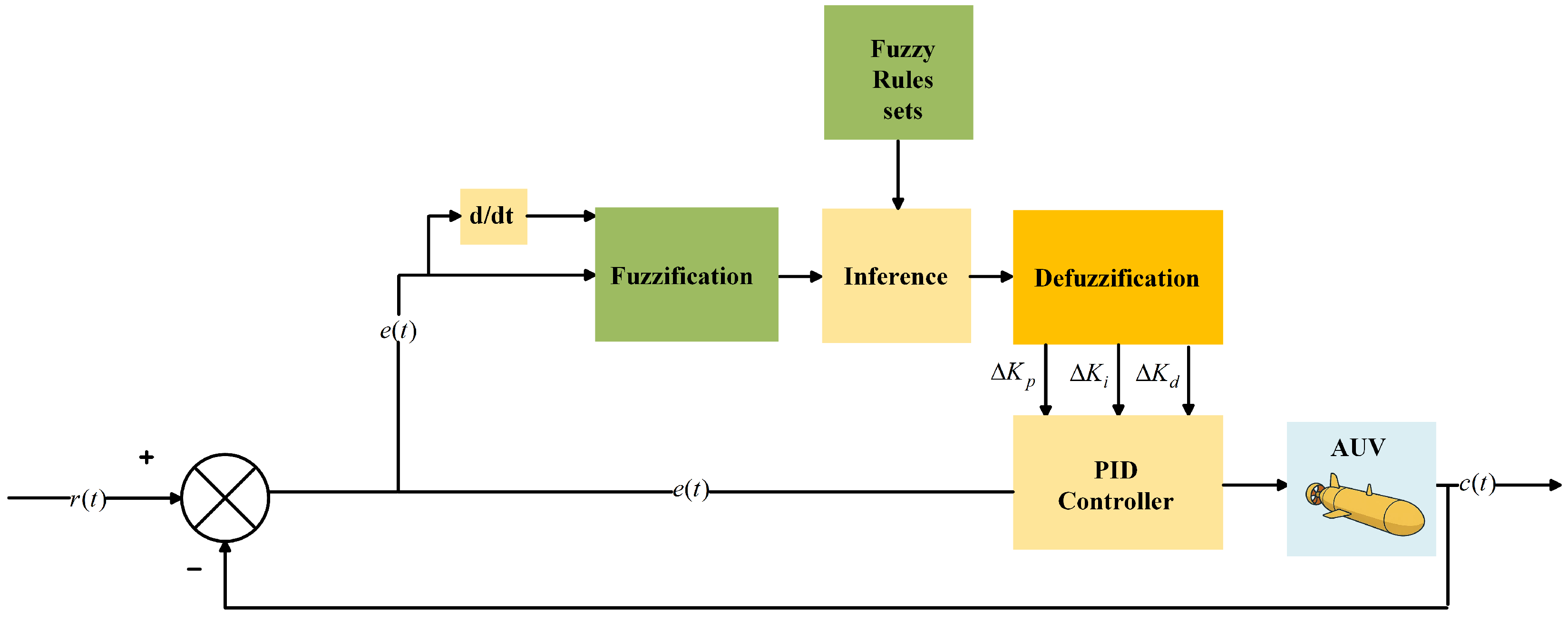
The purpose of the fuzzy control system is to enhance the responsiveness and adaptability of PID control, leading to improved output responses. When designing the fuzzy PID controller of an underwater vehicle, the PID value should have an acceptable response, and the fuzzy logic controller is then used for more tuning. In the process of determining the fuzzy value, it is only necessary to improve the existing PID value. Its system block diagram is shown in
Figure 2.
In the fuzzy PID control system, the motion error
e and the error change
serve as the fuzzy control inputs. The changes
,
, and
in the parameters
,
, and
are used as the control outputs and also as inputs to the PID controller. These changes, combined with the original parameters
,
, and
, form new parameters that can be adjusted in real-time to enhance the control performance of the system. The expressions for these adjustments are as follows:
3.1. Fuzzification
Fuzzification transforms precise input values into fuzzy linguistic terms using a membership function, determining the degree of membership for each discrete input value within each input fuzzy set. The primary objective is to align the input physical signal with the fuzzy control rule base at the controller’s core. During controller design, the magnitude of input and output variables is typically described using terms such as “big,” “medium,” and “small,” with “positive” and “negative” indicating direction, and the zero state also considered. Thus, the fuzzy set for input and output variables is defined as:
{negative large, negative medium, negative small, zero, positive small, positive middle, positive big},
commonly abbreviated as {NB, NM, NS, Z, PS, PM, PB}.
Generally, a larger descriptive vocabulary for input and output variables expands the coverage of control rules but increases the complexity of the control process. Conversely, a limited vocabulary may degrade control performance. Therefore, the choice of descriptive terms should be optimized based on the specific application. To enable the controller to achieve satisfactory tracking performance, Gaussian membership functions are adopted at the boundaries of the domain to ensure smooth transitions, while triangular membership functions are employed in the central region to reduce computational complexity and enhance sensitivity around small errors. The parameters of these membership functions (centers, widths, and slopes) were initially selected according to common practices in fuzzy control design and further refined through iterative simulations, with the objective of obtaining fast convergence and minimal overshoot.
The membership function of fuzzy PID input and output variables of AUV is shown in
Figure 3.
3.2. Fuzzy Control Rules Set and Fuzzy Inference
The control rule is derived from a manual control strategy, which is transformed into numerical values for computation using fuzzy set theory. The corresponding control action is then executed based on the reasoning of these computed results, enabling the actuator to regulate the controlled object and maintain system operation. Typically, fuzzy conditional inference statements are employed to articulate the control strategy.
Fuzzy rules adopt an “If-Then” structure, where the “If” part includes one or more preconditions, and the “Then” part specifies one or more resulting actions. The fuzzy controller’s response to input conditions is determined by processing the rule base module, with rule preconditions directly corresponding to the membership degrees calculated during fuzzification. The membership of a rule is derived from the antecedent condition’s value, typically using a minimum function that assigns the lowest true precondition value as the rule’s membership. When multiple rules apply to the same action, the rule with the highest membership is prioritized.
Based on the above, a general fuzzy rule table can be constructed as shown in
Table 1.
In fuzzy inference, the motion error e and the error change rate serve as the primary inputs to the fuzzy controller. The fuzzy sets of these inputs, combined with the original parameters, are adjusted in real-time to optimize the control performance. This enables the actuator to regulate the controlled object effectively, ensuring stable system operation.
3.3. Defuzzification Method Design
The centroid method calculates the area center of gravity enclosed by the membership function curve, using the horizontal coordinate as the controller’s output value. This value is then scaled to determine the actual control quantity through a proportional adjustment. The output inference and control provided by the centroid method are smooth and continuous, with high sensitivity, enabling appropriate responses to small signal input changes. Compared with alternatives such as the maximum or bisector methods, the centroid method avoids abrupt changes by considering the contribution of all activated rules, which makes it particularly suitable for real-time AUV control. Consequently, this method is employed to address fuzzification.
The mathematical expression is given by:
where
U represents the output value,
denotes the membership function, and the integrals are evaluated over the interval
.
3.4. Stability Analysis and Performance Rationale
The nonlinear state-space expression of the AUV considering kinematic and dynamic coupling is given by:
To facilitate controller design, the system is linearized at the equilibrium point (i.e., all velocities and control inputs are zero) using first-order Taylor expansion:
The closed-loop transfer function for each control channel under PID feedback is:
where
denote the inertial and damping coefficients of each control axis (i.e.,
,
, and
).
In the fuzzy PID controller, the gain parameters are no longer constant but vary with time, based on the system error
and its derivative
. Using the Center of Gravity (COG) method, the time-varying gains are computed as:
where
are normalized membership functions satisfying:
For notational convenience, we write the PID law with online-updated gains as
which is understood pointwise in time (with
t fixed), i.e., it is a notation for the controller law rather than a fixed transfer function. With
t fixed, the local closed-loop mapping is
Theorem 1 (Sufficient Condition for Stability under Fuzzy Gain Scheduling)
. Let the set be defined based on the Routh–Hurwitz stability criterion as:Then the fuzzy PID controller guarantees closed-loop BIBO stability if the following conditions are satisfied:
- (i)
All local gain vectors
- (ii)
The membership functions are continuous and satisfy
Under these conditions, the time-varying gains remain within the convex hull of stable gains: Theorem 1 provides concrete guidance for designing the fuzzy rule base and scheduling gains: (i) select each rule’s consequent gains inside the Routh–Hurwitz stability set for the corresponding SISO channel; (ii) use continuous, normalized membership functions that form a smooth partition of unity so the centroid (COG) defuzzifier returns a convex weighted sum of those stable consequents; and (iii) scale—and, when necessary, saturate—the incremental outputs so the scheduled totals , , remain within at all times.
Stability, in this work, is established theoretically by Theorem 1 and supported by simulations (speed, depth, horizontal, comprehensive, and parameter-variation tests) showing convergent responses without sustained oscillations. Therefore, the fuzzy PID control law is a convex combination of individually stable PID controllers, and the overall closed-loop system remains stable under gain scheduling.
In standard form, the natural frequency, damping ratio, and exponential decay rate are
Convergence speed. A fixed-gain PID must keep
above a safety margin under uncertain
to avoid overshoot and actuator stress, which imposes conservative bounds on
and thus upper-bounds
. The fuzzy-adaptive PID computes
with normalized memberships
,
. When
or
is large, rules increase
(and moderately adjust
), raising
and shortening the transient; as the error shrinks,
is rolled back and
restored for bias removal while keeping adequate damping.
Oscillation suppression. For a second-order mode,
Practically, large
or
triggers higher
with restrained
and non-excessive
, increasing
while keeping
in a safe range; as the error diminishes,
is reduced and
restored so that
does not drop, capping overshoot without losing speed.
4. AUV Control Strategy
The objective of motion control is to enable the system to operate autonomously without manual intervention. The motion control system is responsible for guiding the underwater vehicle to achieve specific control objectives, such as maintaining a desired speed or heading, or following a predefined motion trajectory. The motion control strategy for this project is implemented in the following sections.
4.1. Velocity Control Strategy
The AUV speed is determined by the thrust provided by the actuators. In this simulation experiment, actuator dynamics are neglected, and the controller directly outputs the execution signal to the AUV model. The speed control structure is illustrated in
Figure 4.
The AUV speed control system adopts a single-loop configuration. The reference signal denotes the target speed, while the output V is the actual speed. The controller takes the speed error and its derivative as inputs, and generates the thrust command . To ensure physical feasibility, is subject to a saturation limit of approximately 700 N, consistent with the thrust capability of typical mid-sized AUVs.
4.2. Depth Control Structure
In AUV depth control, direct control of the depth
z by the controller is not feasible; thus, coupling control of the pitch angle
and speed
v is employed to achieve sinking or rising operations. The motion control strategy is implemented as
Figure 5.
The depth control employs a cascade control system due to the need for coupling control of the AUV’s depth. This system utilizes two independent controllers and two feedback loops: the output of the former controller (depth controller) serves as the input to the latter controller (pitch controller), with the output of the latter sent to the AUV. The depth controller acts as the main controller, responsible for depth regulation, while the pitch angle controller, the sub-controller, adjusts the pitch angle to facilitate sinking. The cascade control enhances the dynamic characteristics and control quality of the system, making it suitable for nonlinear and strongly coupled AUV systems.
Since the fall primarily depends on the pitch angle change, the inner loop (pitch control) must respond faster than the outer loop (depth control). Consequently, the PID parameter tuning of the inner loop requires significantly greater adjustment than that of the outer loop.
In this experiment, the AUV’s initial position is on the horizontal plane with an initial z-direction value of 0. According to the definition, a negative pitch angle is required for diving. Thus, the reference signal at the first adder is negative, and the feedback signal is positive, ensuring the AUV dives normally.
For depth regulation, the input reference is the target diving depth, and the output D represents the measured depth, with denoting the pitch angle. A fuzzy PID controller regulates the depth, while a conventional PID controller adjusts the pitch angle. The feedback signals D and are provided to the depth and stern controllers, respectively. The control output is the pitching torque , which drives the stern plane deflection. To reflect actuator limits, the stern plane angle is saturated at , consistent with typical AUV design practice.
4.3. Heading Control Strategy
In under-actuated AUVs, the absence of a propulsion device to directly control the Y-direction freedom necessitates coordination with the main propeller speed and yaw angle to achieve trajectory tracking in the X–Y plane.
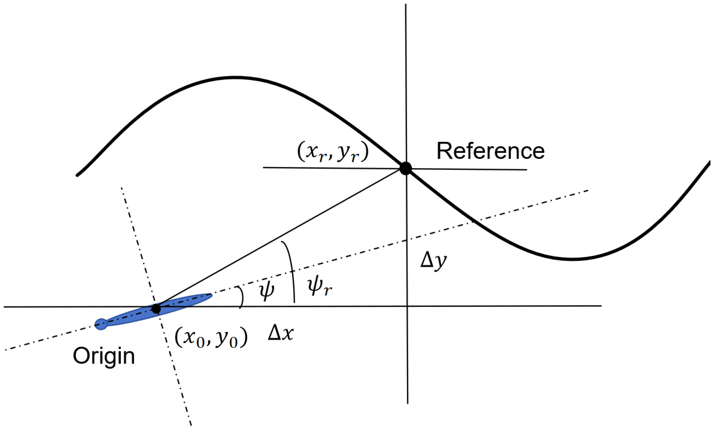
As a result, it is essential to design guidance laws to assist the AUV in maintaining the correct trajectory. Simultaneously, the heading control of the AUV must account for the influence of motion trajectory on a two-dimensional plane. Given the AUV’s course control is determined by its yaw angle, the guidance law must be designed to ensure the AUV reaches the target heading angle. The design of the guidance law, as shown in
Figure 6, is based on the actual location of the AUV
and the reference trajectory location
, with the difference defined as:
The reference heading angle is calculated as:
The block diagram of the heading control strategy is shown in
Figure 7. The fuzzy PID controller produces the heading torque
, with a saturation limit of 1000 N·m imposed to ensure that the control command remains physically realizable.
5. Simulation Experiment
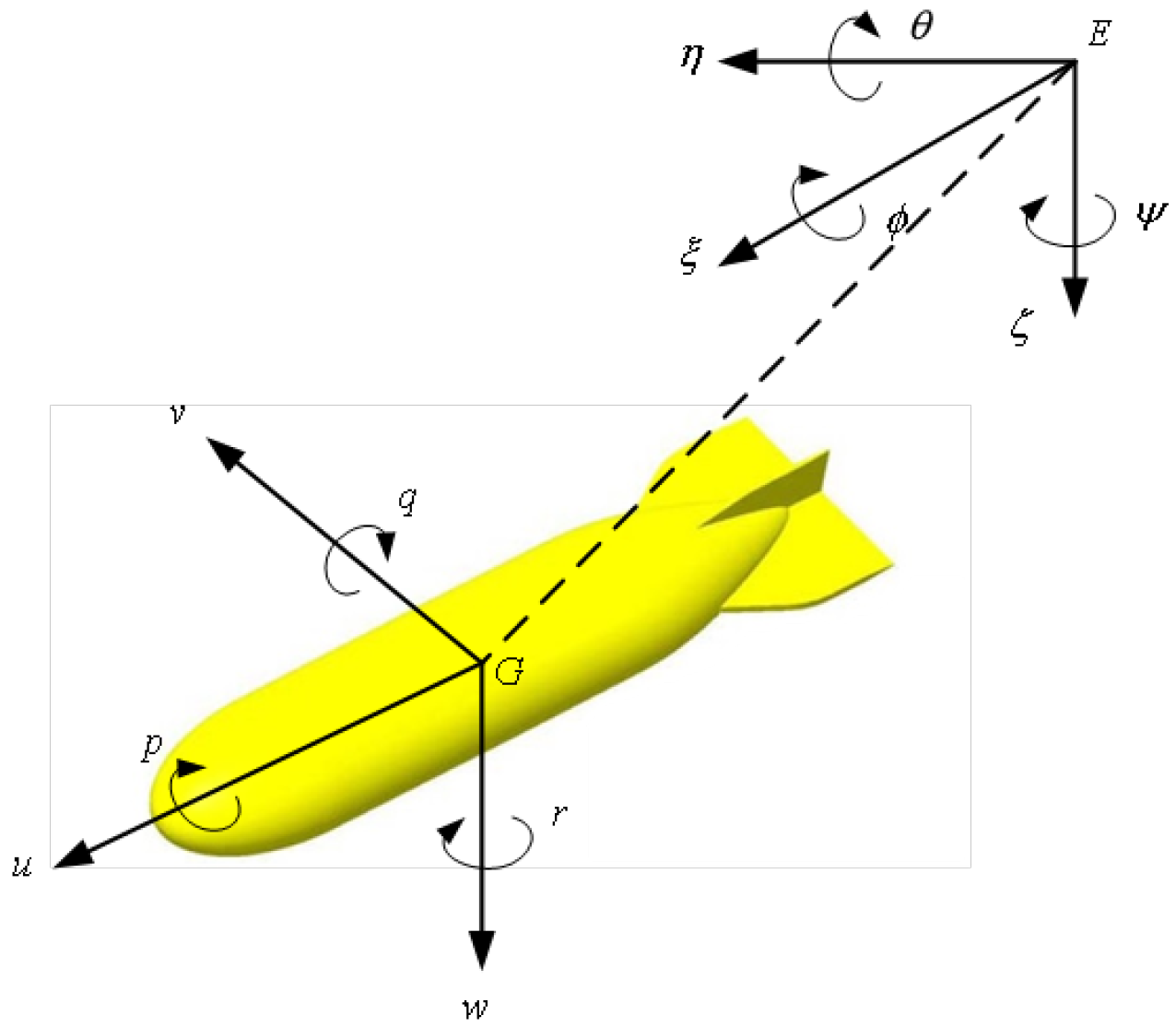
To evaluate the control performance of the proposed strategies under realistic conditions, numerical simulations are conducted based on a 5-DOF model of an underactuated AUV. The physical and hydrodynamic parameters used in the simulation are summarized as follows.
The AUV has a total mass of , with principal moments of inertia and . The added mass coefficients, which account for the inertial influence of the surrounding fluid, are given by , , and for translational motion, and , for rotational motion.
Viscous damping effects are modeled using both linear and nonlinear coefficients. The linear damping terms include , , and , while the nonlinear terms are , , and . For the rotational degrees of freedom, the damping coefficients are given as , , , and .
Other relevant coefficients include the longitudinal metacentric height , which characterizes hydrostatic stability, and the buoyancy force , which is set slightly higher than the gravitational force to ensure positive buoyancy.
All baseline controllers were tuned with the same systematic procedure under identical constraints (fixed sampling time , actuator saturation and rate limits, first-order derivative filtering, and identical reference signals). For the PID controller, the initial gains were obtained using the Ziegler–Nichols (ZN) method, followed by performance-based refinement to reduce overshoot and the integral of absolute error (IAE), while ensuring reasonable rise and settling times. The PID controller was tuned once under the nominal case and then kept fixed across all experiments. For the fuzzy controller, the same input variables, membership function types, and inference mechanism as in the fuzzy adaptive PID were adopted to ensure fairness. The rule base was constructed using a standard Mamdani-type design and fine-tuned with the same performance indices as for PID.
5.1. Speed Control Experiment
To simplify the speed-loop design, only the surge motion is considered, neglecting couplings with sway/heave and surge-direction disturbances. Around the operating point the surge subsystem reduces to a first-order model . Under unity-feedback PD/PID control the closed loop has a single real pole , hence the time constant . The step response is therefore non-oscillatory, and it follows that while : only the proportional gain can shorten the response, whereas larger actually slows the convergence; the integral action mainly removes bias without reducing .
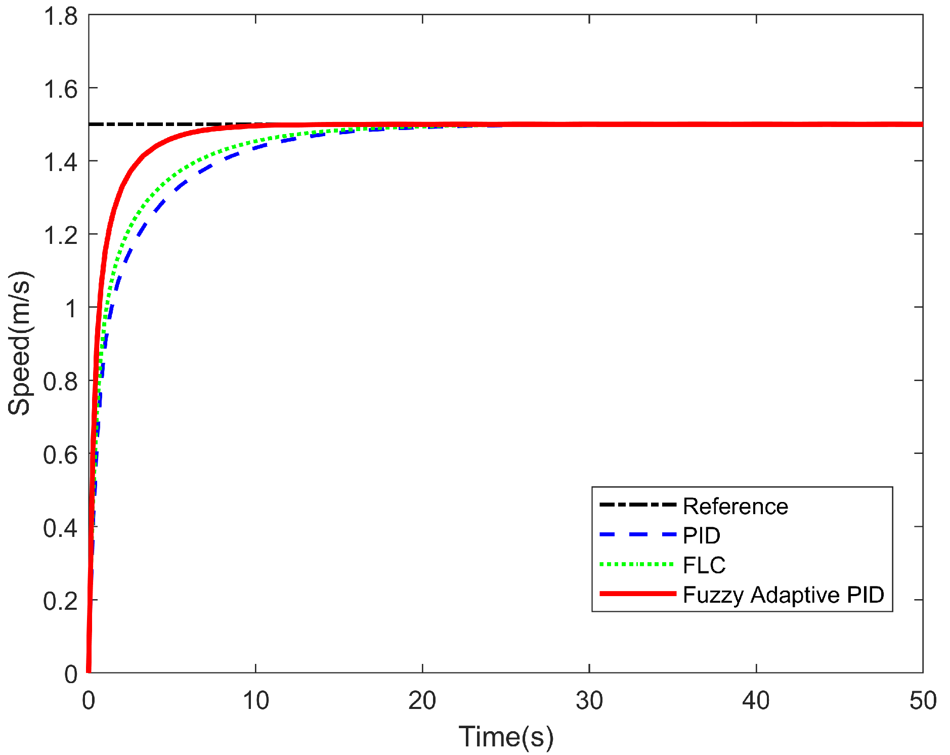
As shown in
Figure 8, both PID (
) and FLC yield reasonable speed responses. Embedding a fuzzy adaptive mechanism into the PID framework further accelerates convergence without increasing overshoot, demonstrating the benefit of online parameter adaptation. Quantitatively, the sum-to-one normalized RMSEs are 0.375 (PID), 0.343 (FLC), and 0.282 (Fuzzy Adaptive PID); the corresponding effective time constants are 4.72 s, 4.63 s, and 3.69 s, respectively. For idealized speed regulation with negligible disturbances and mild set-point profiles, a proportional strategy can already meet basic requirements; the adaptive design mainly provides faster convergence and improved tracking accuracy under non-ideal conditions.
This structure is illustrated in
Figure 9, where the surface
decreases monotonically with
and shows limited benefit from
.
5.2. Constant Depth Motion Experiment
The depth control of an AUV primarily concerns the regulation of heave motion to maintain a prescribed depth. The constant-depth tracking experiment is a fundamental benchmark for vertical control performance.
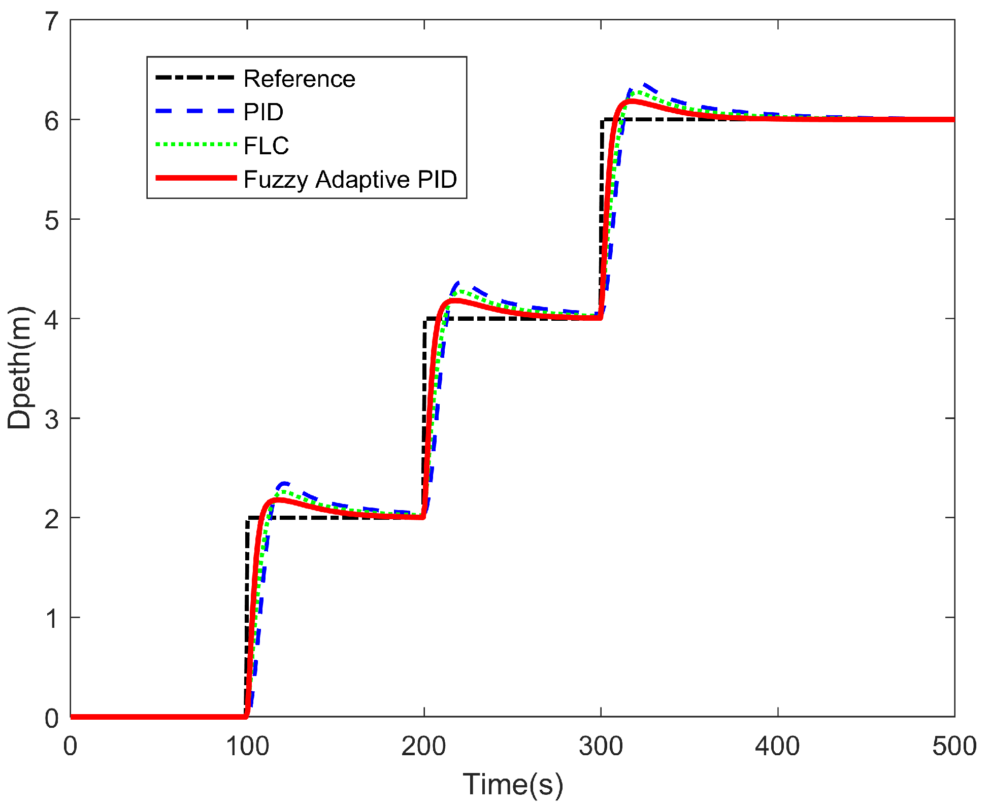
As illustrated in
Figure 10, continuous constant-depth tracking reveals the behavior during diving and surfacing and under different operating depths. The baseline PID controllers were tuned empirically with inner-loop gains
and outer-loop gains
. The fuzzy adaptive PID controller shortens the rise interval and suppresses overshoot, yielding faster and more stable regulation than PID and FLC. Quantitatively, the normalized-RMSEs are 0.415 (PID), 0.327 (FLC), and 0.258 (Fuzzy Adaptive PID); the averaged step-wise
values are 9.69 s, 7.01 s, and 5.01 s, respectively.
5.3. Horizontal Motion Experiment
The horizontal motion of an AUV serves as an important benchmark for lateral control while neglecting vertical disturbances. In this experiment, the vehicle follows a predefined sinusoidal trajectory along the water surface.
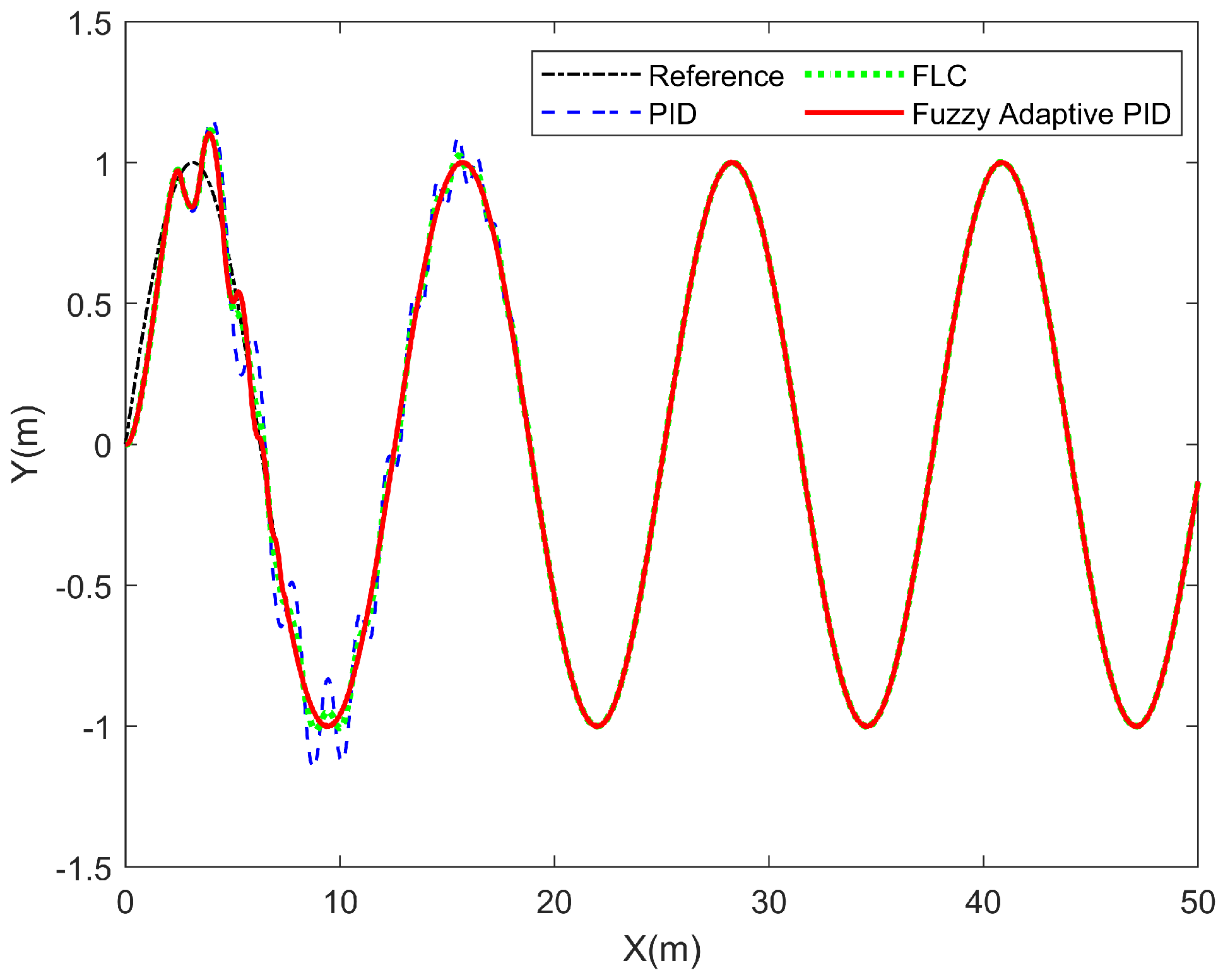
As shown in
Figure 11, all controllers achieve rapid convergence to the sinusoidal reference with comparable rise segments. The baseline PID was tuned empirically with
. The main difference lies in the suppression of oscillations around the trajectory. Quantitatively, the normalized RMSEs are 0.460 (PID), 0.284 (FLC), and 0.257 (Fuzzy Adaptive PID), indicating that the proposed controller yields the smallest relative error share. These results highlight that, under sinusoidal tracking, the advantage of the fuzzy adaptive PID strategy is reflected in stronger oscillation suppression and enhanced trajectory stability rather than distinct rise times.
5.4. Comprehensive Motion Experiment
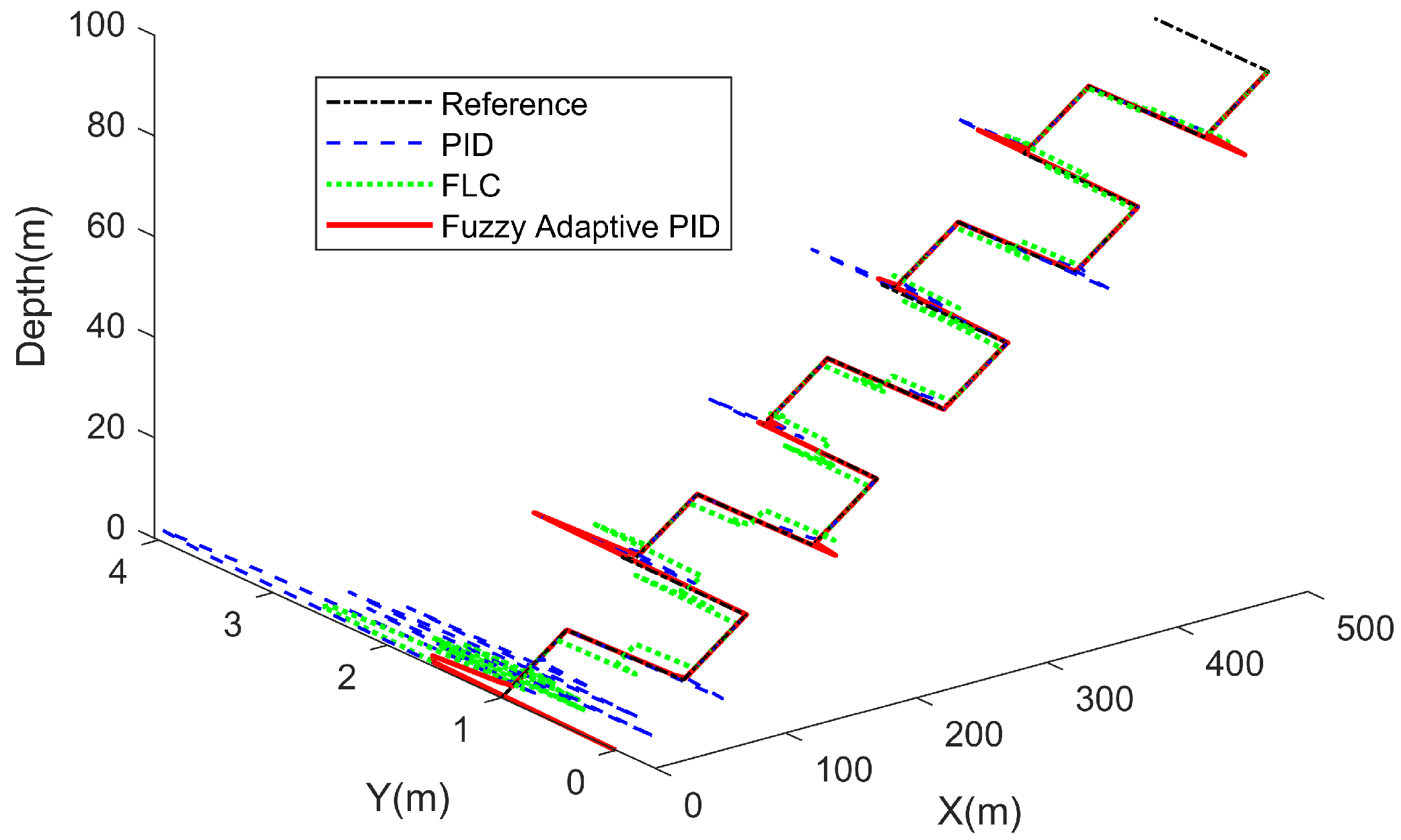
After evaluating the AUV’s performance under individual control modes, a comprehensive experiment is conducted to emulate real-world operating conditions. In this test, a relatively complex trajectory is designed: the AUV starts from a given point, descends steadily along the z-axis, moves forward at a constant velocity in the x-direction, and simultaneously follows a continuous pulse trajectory in the y-direction.
As illustrated in
Figure 12, the PID controller exhibits noticeable oscillations at the beginning of the maneuver and requires a longer distance to stabilize. Moreover, substantial overshoots occur at each turning point of the pulse trajectory, indicating limited dynamic adaptability. The FLC achieves only marginal improvements over PID, as its suppression of overshoot and trajectory smoothing remain insufficient under the tested conditions. In contrast, the fuzzy adaptive PID controller demonstrates superior performance across multiple aspects: although a moderate initial overshoot is observed, it converges rapidly without sustained oscillation, and overshoot at pulse corners is markedly reduced. Quantitatively, the normalized RMSEs are 0.405 (PID), 0.334 (FLC), and 0.262 (Fuzzy Adaptive PID), confirming that the proposed controller achieves the smallest relative error share.
In summary, under this extreme and comprehensive test scenario, the fuzzy adaptive PID control strategy exhibits clear advantages, effectively handling coupled multi-dimensional motion and outperforming both PID and fuzzy logic control approaches.
5.5. Parameters Variant Tracking
To emulate practical uncertainties, the PID parameters
,
, and
are kept unchanged, while the added-mass matrix is perturbed by scaling the hydrodynamic coefficients in
by a factor of 1.2. This adjustment evaluates the controllers’ adaptability to parameter variations.
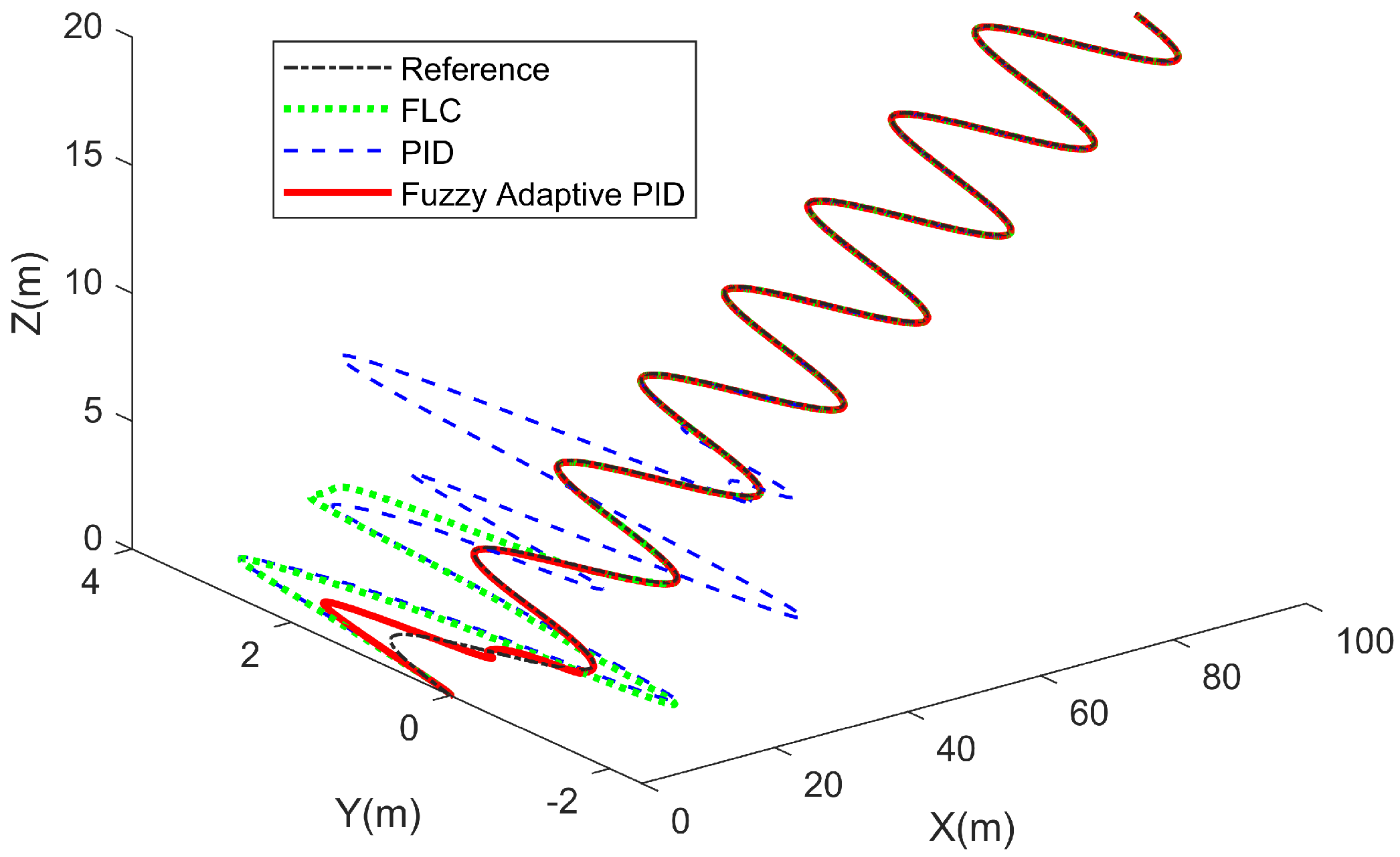
In this test, the AUV continues descending along the
z-axis, moves at a constant speed in the
x-direction, and tracks a sinusoidal trajectory in the
y-direction. As shown in
Figure 13, after perturbing the hydrodynamic parameters, the PID controller degrades markedly, exhibiting slower convergence and evident oscillations. The fuzzy logic controller provides improved stability relative to PID, yet still suffers performance loss under parameter variations. In contrast, the fuzzy adaptive PID controller maintains excellent performance: its online gain adaptation enables rapid convergence and effective suppression of oscillations. Quantitatively, the normalized RMSEs are 0.433 (PID), 0.367 (FLC), and 0.200 (Fuzzy Adaptive PID), confirming its superior adaptive performance.
In summary, under parameter perturbations representative of uncertain or time-varying hydrodynamic environments, PID and FLC controllers struggle to maintain consistent performance. The fuzzy adaptive PID controller, by dynamically adapting its gains, achieves higher robustness and is better suited for deployment in complex and uncertain underwater conditions.
5.6. Disturbance Rejection Experiment
To further evaluate robustness and to provide comparison with an advanced method, an additional experiment was conducted under sinusoidal acceleration disturbances that emulate surface wave effects. The proposed fuzzy adaptive PID controller was compared against the conventional PID and the differential flatness-based feedback linearization (DFFL) controller.
In this setup, a deterministic sinusoidal disturbance was applied in the surge and sway directions to mimic a long-period ocean swell. The disturbance was active only within the interval 60–120 m. Its parameters were set as m/s2 (surge), m/s2 (sway), and Hz (wave period of 10 s), with a phase difference between surge and sway components to emulate oblique wave forcing. No perturbations were added in the heave or rotational channels.
For the DFFL controller, the design is based on the differential flatness property of the underactuated AUV. The flat outputs were chosen as surge velocity
u, pitch angle
, and yaw angle
. Through input–output feedback linearization, the dynamics were expressed in affine form
where
represents the nonlinear terms,
is the input matrix, and
v is the virtual input used to shape the tracking error dynamics of the flat outputs. The reference trajectory and its derivatives were obtained through flatness mapping. For tuning, the surge channel followed a first-order error dynamics
with
. The pitch and yaw channels were tuned as second-order error dynamics
, with critical damping
and natural frequency
rad/s, yielding
and
.
As illustrated in
Figure 14, the DFFL controller achieves a competitive response in the nominal condition; however, when disturbances are introduced, it exhibits strong oscillations and degraded robustness, even worse than the conventional PID. The PID controller maintains moderate stability but shows noticeable tracking deviations during wave peaks. By contrast, the fuzzy adaptive PID controller closely follows the reference trajectory with minimal oscillations and the least degradation under disturbance. Quantitatively, the normalized RMSE values are approximately 0.361 (PID), 0.450 (DFFL), and 0.189 (Fuzzy Adaptive PID), confirming that the proposed controller achieves the smallest relative error share.
In summary, this experiment highlights the superior robustness of the fuzzy adaptive PID strategy, effectively resisting sinusoidal wave-like disturbances and outperforming both conventional PID and DFFL control approaches.
6. Conclusions
and Future Work
This work designed and evaluated a tracking control scheme for an underactuated AUV based on a simplified 5-DOF kinematic–dynamic model. By integrating fuzzy logic with PID, a fuzzy adaptive PID controller was developed to manage AUV behavior. A series of tests—including constant-depth maneuvers, horizontal motion, comprehensive maneuvers, and parametric variations of hydrodynamic coefficients—were conducted to assess trajectory tracking. The results show that the fuzzy adaptive PID achieves faster convergence and smaller tracking errors than conventional PID, with clearer advantages on complex trajectories and under parameter changes.
6.1. Limitations
(i) Part of the fuzzy rule base was initialized heuristically: in regions with large error magnitude and high error rate, the consequents were designed to increase and while suppressing , prioritizing rapid error reduction and damping; in the central regions, the consequents were adjusted through simulation to balance steady-state accuracy and overshoot. Such heuristic initialization may limit generalization when the hydrodynamic coefficients, coupling strength, or operating conditions deviate significantly from those considered here.
(ii) The 5-DOF model neglects roll dynamics and omits higher-order hydrodynamic effects. Although this simplification is adequate for the tested scenarios, it may under-represent highly dynamic maneuvers or asymmetric vehicle configurations.
(iii) Robustness was examined through variations in hydrodynamic coefficients and actuator saturation. However, stochastic sensor noise and external environmental disturbances such as ocean waves and background currents were not explicitly included in this version, in order to keep the controller effects interpretable.
(iv) Experimental validation was limited to the tested scenarios. Hardware-in-the-loop simulation and full-scale field trials were not carried out.
6.2. Future Work
(i) Data-driven refinement of the heuristic rules and consequents, combined with the exploration of online adaptation strategies.
(ii) Extension of the simulator to include stochastic noise sensors, as well as representative ocean wave and current models, together with estimator-in-the-loop evaluation, to complement the current parametric-variation tests.
(iii) Deployment-oriented studies focusing on typical missions, such as pipeline inspection for constant-altitude tracking, structured harbor surveys, detailed bathymetric surveys, and low-altitude seabed mapping under background currents. Corresponding controller refinements and anti-windup implementations under actuator limits will also be explored.
(iv) Hardware-in-the-loop experiments and field trials will be conducted. When required by the application, the model and controller will be extended to incorporate roll dynamics and to address operation in high sea states.
