Abstract
The development of electromechanical linear actuators (EMLAs) aims at compactness, energy efficiency, and high reliability. Conventional design methods often rely on costly prototypes and individual considerations of mechanics, electromagnetics, and control dynamics. This leads to long development cycles, inadequate treatment of nonlinear effects, and suboptimal performance. To address these challenges, our paper introduces a novel hybrid design methodology, integrating Analytical Modeling, Finite Element Analysis (FEA), Genetic Algorithms (GAs), and targeted experiments. Analytical Modeling provides rapid sizing, FEA combined with a GA refines geometry, and targeted experiments quantify nonlinear effects (friction, wear, thermal variability, and dynamic resonances). Unlike conventional methods, the integration is performed within iterative loops, using empirical data to refine simulation assumptions. As a result, development time is reduced by 30% and nonlinear effects are precisely addressed. The method is demonstrated on an automotive-grade EMLA. Its design is based on a claw-pole Permanent Magnet Stepper Motor, a trapezoidal lead screw, and an open-loop control with Hall effect end-position detection. After applying the method, the EMLA delivers more than 40 N of push force and achieves 600,000 actuations under the required conditions, making it suitable for various applications.
1. Introduction
Road transport accounts for 20% of global CO2 emissions [1] and has a major impact on climate change [2]. Decarbonization strategies prioritize enhanced public transport, zero-emission fuels, and vehicle electrification [3], with EMLAs increasingly gaining a key role. Compared to hydraulic/pneumatic and active material-based actuators [4], EMLAs provide cleaner operation, a higher force-to-size ratio, and improved energy efficiency. These advantages enable widespread use of EMLAs across automotive systems (engine valve management [5], clutch actuation [6], active suspension control [7], seat adjusters [8], window lifters [9], brake assist [10], and adaptive headlights [11]), medical devices (surgical robots [12], exoskeleton limbs [13], wheelchair braking systems [14], patient beds [15], and drug dosing machines [16]), and industrial automation and other industries (assembly automation [17], marine risers [18], aerospace flight control systems [19], and smart home automation [20]).
EMLAs (e.g., Figure 1) need to balance the following multidisciplinary and often conflicting design trade-offs, which require simultaneous assessment, shown in of [21]:
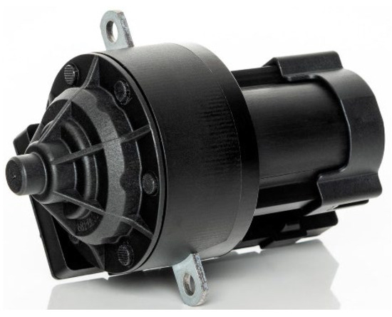
Figure 1.
An example of an EMLA utilizing a Permanent Magnet Stepper Motor, a lead screw, and open-loop control for opening and closing the automotive headlight mechanism.
- Maximizing output force while consuming minimum energy (e.g., minimum 40 N at maximum 0.8 A and 12 V).
- Achieving compact design space (e.g., maximum 108 × 54 mm) and low noise levels (< 40 dB (A) at a distance of 0.3 m).
- Ensuring reliability within the full lifecycle of 15 years (e.g., equivalent to 600,000 actuations) while being exposed to harsh conditions (temperature range of −40 °C to 105 °C, 95% relative humidity, high vibrations, and presence of contaminants like metallic particles).
- Incorporating low-cost, recyclable materials manufactured in compliance with sustainability goals [22].
A detailed list of requirements, supported by international standards, is provided in. in chapter 3.1. Requirements.
Combinations of these challenges exponentially accelerate performance degradation and induce premature wear-based failures [23]. To avoid high replacement costs, productivity losses, and safety risks, mitigation must be performed in early design phases [24]. However, the existing design methods are limited in managing the complex and nonlinear behavior of EMLAs (Table 1). This includes temperature-dependent friction, subharmonic resonances, hysteresis effects, manufacturing tolerance accumulation, wear-induced parameter drift, and multiphysics coupling of multiple physical domains.

Table 1.
Strengths and limitations of design methods/approaches.
1.1. Limitations of Existing Design Methods
Analytical Modeling is effective for initial sizing [25] and basic electromagnetic calculations [26] but falls short with complex geometries and multi-physics interactions (e.g., magnetic flux non-uniform distribution or thermal gradients). Additionally, nonlinear phenomena (e.g., friction, backlash, and hysteresis) lead to inaccurate performance predictions [27], numerous prototyping iterations, and implementation of over-conservative safety factors [28].
FEA improves nonlinear modeling accuracy but at the expense of long computation time, convergence issues, sensitivity to boundary conditions, and material property assumptions. By using analytical FEA models, the computation time can be reduced for several orders of magnitude [29], but at the expense of lower accuracy [30]. Despite efforts, EMLAs are too complex for the FEA-only approach and need a more systematic approach.
Model-Based Design (MBD) provides a systematic approach with reduced computation time and early system-level trade-offs [31]. For example, system-level block diagram simulations in Matlab Simulink (version 23.2, Matlab R2023b), may encounter difficulties associated with manufacturing variability, oversimplified electromagnetic models, dynamic coupling, subharmonic resonances prediction, and nonlinear friction modeling [32]. Even in cases of more advanced nonlinear dynamic models, such as Karnopp [33] or LuGre [34] friction models, these designs struggle with nonlinearities, interface assumptions, and unpredictable degradation behaviors over time [35].
Promising approaches that aim to improve modeling precision and include nonlinearities are data-driven methods and Machine Learning (ML). Even though these methods rely on large-scale and high-quality datasets, they have shown success in predicting force–speed behavior [36], estimating component failure [37], and adapting control strategies for friction error compensation [38]. Although high-quality experimental data [39] is often unavailable or cost-restrictive, optimization techniques and physical experimentation with surrogate modeling are utilized instead.
1.2. Optimization and Experimental Gaps
Optimization techniques used in EMLA development are based on mathematical algorithms and are divided into Single-Objective Optimization (SOO) or Multi-Objective Optimization (MOO) approaches. SOO can be deterministic (gradient-based, derivative-free, convex, structured, or recursive) or stochastic (evolutionary, swarm intelligence, hybrid, metaheuristic, or physics- or nature-inspired). In low-dimensional problems with a good initial estimate of the optimal solution location, deterministic algorithms (e.g., Newton’s Method) are typically faster than stochastic ones. However, in more complex and non-convex objective functions, they may fail to escape local minima, meaning that stochastic algorithms (e.g., Genetic Algorithms (GAs), Particle Swarm Optimization (PSO), and Differential Evolution (DE)) are more robust and perform better in the global search for optimal solutions. A trade-off between speed and accuracy can be achieved by combining deterministic and stochastic approaches. For example, GAs and PSO explore large design spaces while Newton’s Method performs local refinement.
In cases using EMLAs, which typically involve multiple design goals (e.g., force, cost, efficiency, noise, size, and reliability), MOO should be employed. However, having more than five competing objectives, evolutionary algorithms (e.g., Non-dominated Sorting Genetic Algorithm II (NSGA-II)) experience slow convergence, high parameter sensitivity, and a large computational burden. This means that experiments are necessary to address nonlinear and system-level effects. As a result, DfX, Design of Experiments (DoE), and surrogate modeling are used to evaluate reliability, manufacturability, safety, and cost aspects [40]. Design of Experiments (DoE) and surrogate modeling help to determine the optimal number of prototypes and test iterations. Simulation assumptions are validated by accounting for real-world nonlinear effects and manufacturing variability.
1.3. Paper Contribution and Scope
No single method can universally, accurately, and efficiently resolve the full range of trade-offs in EMLA development. Traditionally, they are utilized in a sequential design process, which often leads to suboptimal results and long development cycles. Therefore, this paper demonstrates a comprehensive hybrid design methodology that integrates the advantages of modeling, simulation, optimization, and experimental validation into the following components:
- Analytical Modeling for preliminary sizing and mechanical architecture selection.
- FEA for multiphysics electromagnetic motor simulation.
- GA optimization to refine motor topology and maximize torque output.
- Targeted physical experiments to capture real-world friction losses and validate performance under manufacturing variability.
The integration interest lies in establishing the iterative feedback loops for empirical refinement of analytical and numerical models. As a result, it reduces costly redesign and prototype iterations, shortens development time, enhances reliability, and explicitly addresses nonlinear effects (e.g., friction, resonance, and thermal losses). The proposed methodology is demonstrated through the development of a new automotive-grade EMLA for adaptive LED headlight actuation, in which the final architecture includes a rare-earth claw-pole Permanent Magnet Stepper Motor, a trapezoidal lead screw, and a cost-effective open-loop control system with Hall-sensor-based end-stop detection.
2. Hybrid Design Optimization Methodology
The development of complex mechatronic EMLAs requires a systematically structured and agile design framework such as the commonly used V-Model [41]. The framework utilizes a multidisciplinary collaboration of different engineering fields (Figure 2). Elicitation of requirements is followed by the design phase, system integration, verification, and final validation.
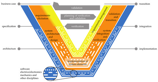
Figure 2.
V-Model for new VDI 2206 [41].
The traditional V-Model can be too rigid and time-consuming for modern agile engineering cycles (sequential process with late-stage verification phase). As an improvement, the “Incremental V-Model” is introduced [42]. By overlapping development phases, verification time can be reduced by 50% and quality improved by 45%. In addition, the “Slicing V-Model” [43] is proposed to improve traceability and robustness of requirement management by slicing development into smaller tasks. Further improvements are presented in the form of the “Digital Variant Design V-Model for Rapid Product Development” [44] and by “Expanding the Classical V-Model for the Development of Complex Systems Incorporating AI” [45].
Despite these advancements in concurrent engineering, requirements management, and AI-supported performance simulations, real-world nonlinear effects are difficult to capture due to the complexity of EMLAs. To address these challenges, we propose a hybrid design methodology that balances simulation with practical experimentations, minimizing both cost and development time. The key process steps include the following (Figure 3):
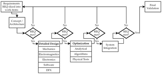
Figure 3.
Optimized V-Model-based approach using a combination of multiple approaches.
- 1.
- Requirements Management
A hybrid combination of Incremental and Slicing V-Models enables fast and traceable development. Requirements (REQs) are decomposed into manageable work items, which facilitates incremental verification loops at each design stage and reduces the risk of late-stage failures.
- 2.
- Concept and Architecture
Early design exploration of multiple concepts is driven by analytical pre-sizing models, allowing rapid assessment of performance metrics. It enables quick architecture selection before engaging in computationally intensive simulations.
- 3.
- Detailed Design
A multiphysics approach integrates mechanical, electromagnetic, electronic, software, and DfX disciplines. This ensures a robust, manufacturable actuator design aligned with system-level REQs.
- 4.
- Design Optimization
Genetic algorithms optimize motor geometry for performance and compactness. Analytical models are used in parallel to fine-tune the mechanical transmission system. Targeted physical tests supplementing the process are conducted to verify critical parameters.
- 5.
- System Integration
Sub-systems are integrated and evaluated against system-level requirements. Continuous verification loops allow earlier detection of all failures.
- 6.
- Final Validation
Final validation is conducted on a custom test bench that replicates the full actuator use case (e.g., actuation in LED headlight mechanisms). It validates force output, control accuracy, reliability, and robustness under real-world conditions.
The unique combination of these steps provides a modular, scalable, and iterative workflow, supported by continuous and short feedback verification loops. The proposed model ensures that EMLA performance, manufacturability, and reliability are verified at every design stage. These integrated feedback loops are a critical building block that significantly reduces the number of costly redesign iterations and enables efficient development for a wide range of cost-sensitive applications.
3. Case Study of the Proposed Method for EMLA Design Optimization in Headlights
3.1. Requirements
Modern headlight systems of battery electric vehicles (BEVs) strive for high performance, energy efficiency, reliability, and visual appeal. In this novel LED matrix headlight system (Figure 4), the custom-made EMLA must incorporate these targets into the adaptive mechanism switching between daytime running lights and fully engaged matrix LED lights at night.
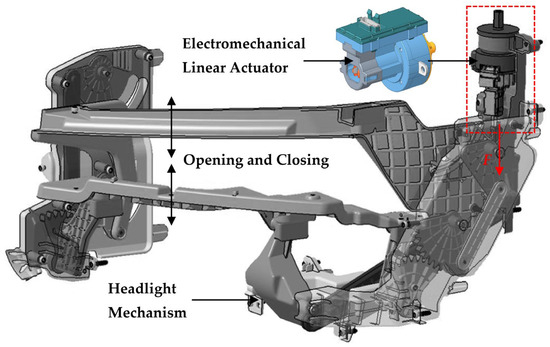
Figure 4.
The position of the EMLA in the headlight’s mechanism.
To ensure its function, the EMLA must meet several demanding requirements (Table 2), including size compactness, stroke positioning accuracy, high push and holding forces, low noise level, reliability, and energy efficiency under harsh environmental conditions.

Table 2.
EMLA requirements.
3.2. Concept Architecture
Several types of motors, transmissions, and controls were considered in the process of selecting EMLA architecture. The most suitable combination, which meets all the requirements and optimally balances performance, cost, and manufacturability, consists of a stepper motor, a lead screw, and open-loop control:
- (a)
- Stepper Motor:
- A Permanent Magnet Stepper Motor (PM-SM; Figure 5) is an optimal solution to achieving high energy efficiency, high torque at low-speed operation, and cost effectiveness. The Variable Reluctance Stepper Motor (VR-SM; Figure 6) costs less but also delivers lower performance, while the Hybrid Stepper Motor (H-SM; Figure 7) has the highest performance but significantly higher cost.
- The PM-SM’s bipolar winding configuration is used instead of a unipolar variant. It allows full coil utilization, achieving 30–40% more torque at lower electric currents.
- Stator’s claw-pole shape ensures compactness, short magnetic flux paths, and minimized magnetic losses.
- The 48-full-step configuration offers an optimal balance between step precision, manufacturability, and cost.
- Hybrid PM-SM and H-SM versions are applicable but too costly to implement [57].
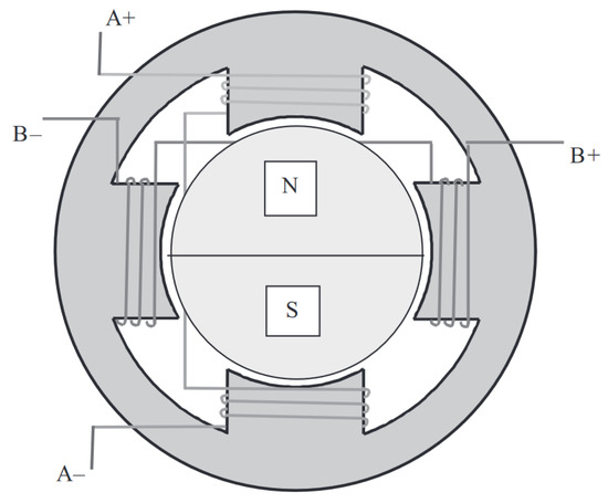
Figure 5.
Permanent Magnet SM [58].
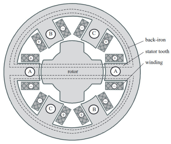
Figure 6.
Variable-reluctance SM [58].
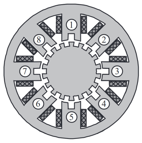
Figure 7.
Hybrid SM [58].
- (b)
- Lead Screw with Nut:
- The advantage of a lead screw and nut assembly is high load capacity within a compact size and cost-effectiveness.
- A trapezoidal thread profile and a flank angle of 30° ensure enough friction and can achieve efficiency in the range of 30–50%.
- The combination of stainless steel and brass alloy optimally balances robustness, friction, and wear.
- The application of high-end lubricant lowers the acoustic noise and maintains the friction coefficient in the range of 0.05 to 0.15.
- The initial size determination is based on balancing manufacturability, wear effects, and buckling resistance. For example, outer diameters greater than 4 mm increase the EMLA’s overall size, inertia, and cost, while outer diameters below 4 mm may lead to manufacturability issues and excessive cost.
- Even though compared to lead screws, ball screws are superior in precision and efficiency, with minimal backlash, lower friction, and wear, they are costlier, non-self-locking, and unable to meet the size requirements. Therefore, lead screws with nuts are an optimal cost-performance solution.
- (c)
- Bearings:
- Pre-lubricated deep-groove ball bearings minimize torque losses and wear.
- These bearings ensure reliability over the required lifetime and provide good support for axial or radial loads while experiencing frequent movement reversals.
- (d)
- Control system:
- Open-loop control is preferred over closed-loop control for simplicity and cost.
- Closed-loop control relies on encoders, while open-loop control employs step counting and end-position detection with simple and cost-effective Hall-effect sensors.
- The half-step mode provides precise open-loop positioning, while smooth operation is achieved using the trapezoidal speed profile (less jerky and less overshooting compared to triangular or S-curve profiles).
3.3. Detailed Design
The conceptual design is based on analytical equations (Table 3). The goal is to perform pre-sizing of the complete actuator. All calculations are validated by checking compliance with the requirements. If the requirements are not met, the design parameters are changed accordingly.

Table 3.
Conceptual design parameters.
The conceptual design and pre-sizing of the EMLA are verified with several design verification loops. Once all requirements are theoretically satisfied, the process moves to the next phase of Multi-Objective Optimization.
3.4. Optimization
The level of an EMLA’s linear force depends on the generated motor torque, the lead screw’s factors (pitch, efficiency, and efficiency), control strategy, and friction losses. To meet the requirements and achieve optimal performance within a compact design envelope (Figure 8), the motor, lead screw–nut pair, and control strategy must be optimized and verified for compliance with the technical requirements.
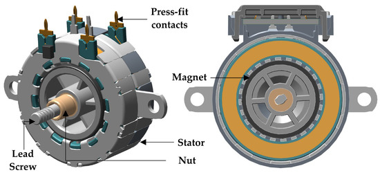
Figure 8.
Compact claw-pole Permanent Magnet Stepper Motor architecture.
3.4.1. Optimization of Permanent Magnet Stepper Motor
The goal of optimizing the stepper motor is to maximize the output and holding torque, which are directly proportional to the maximization of magnetic flux density. Analytical approaches based on air-permanence models allow magnetic saturation at pole tips, resulting in insufficient accuracy. In contrast, 3D FEA provides significantly higher precision, but at considerable computational cost. A compromise can be reached by combining analytical models and FEA at the expense of accuracy or by combining 3D FEA and GAs [59]. The key areas of consideration in increasing magnetic flux density while ensuring continuous compliance with the requirements are as follows:
- Claw-pole architecture, which ensures compactness, mitigates eddy current and hysteresis, and enhances thermal behavior.
- Stator segmentation into two symmetrical halves [60], which reduces magnetic saturation risks and facilitates coil excitation at lower current levels.
- “Amper-turns” balance between maximum performance and minimum inductance [61].
- High-permeability materials, such as NdFeB for the rotor and DX-grade steel for the stator. The higher the material grade, the greater the magnetic saturation risk. Torque output can be limited, and a significant cost increase occurs [62].
- Dynamic performance considerations include minimization of rotor inertia with a cup-shaped design [63], shorter rotor length, increased number of stator poles [64], and reduced impact of natural frequencies via structural FEA (Figure 9) [65].
 Figure 9. Structural FEA (a) and simulations of natural frequencies (eigenvalues) (b).
- The air gap between stator poles and rotor magnet, where an air gap reduction of 25% increases the torque by 34% [66]. The optimal range is between 0.1 mm and 0.2 mm to maintain the balance between manufacturing variability and maximum detent torque.
- Stator geometry included GA optimization of the claw-pole shape (pole, root, and slot). An increasing number of stator poles combined with rotor multipole magnetization [67] enables more magnetic interactions and higher magnetic flux density. Furthermore, skewing poles, rounding edges, and slot size optimization would additionally increase the magnetic flux density [68], which is not physically possible in our miniature-sized motor. The usual rule of thumb for claw-pole stator design [69] is that optimal root width is from 1.2 to 1.5× of the pole tip width, and the pole trapezoidal shape must avoid sharp root corners < 0.5 mm.
Several verification loops included simulations using an advanced genetic algorithm optimizer with three variables. Their initial values and value ranges are stated in Table 4:

Table 4.
Variables for GA optimization.
For the GA setup, 30 individuals were used for the parent selection, mating pool, and children generation. This value represents a balance between exploration and computational cost, providing sufficient diversity while remaining feasible for FEA-based evaluations. The Pareto front was limited to 10 individuals. This elitism strategy ensures that the top-performing candidates are preserved across generations, while the remaining 20 slots in the population are allowed to be filled with new offspring. By restricting the Pareto survivors to 10 (one-third of the population), the optimizer avoids premature convergence and maintains a healthy balance between exploration and exploitation. The stopping criteria are set to the maximum available duration limit of 2 weeks. The results showed that the maximum torque of 28.4 mN·m mN·m is achieved with the slot = 1.7 mm, the root = 0.5 mm, and the pole = 5.6 mm (Figure 10). This represents a 21.3% increase on the initial value.
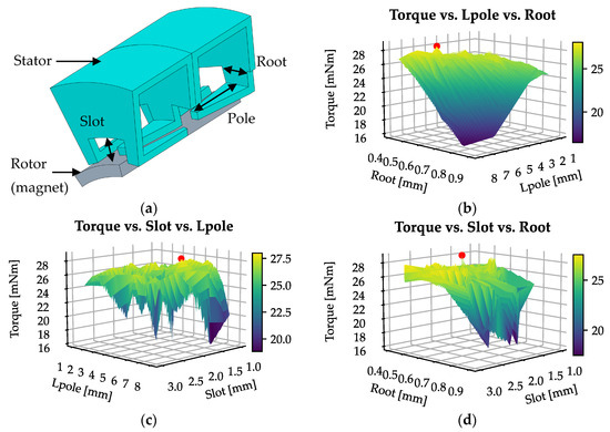
Figure 10.
GA optimization determined the stator geometry (a) for reaching the highest torque. The graph (b) shows torque dependency on Root and Pole, (c) shows torque dependency on Pole and Slot, and (d) shows torque dependency on Root and Slot.
- A rotor magnet with multiple poles increases magnetic interactions. Magnet thickness has the highest influence on holding torque [70]. Narrowing the magnetic poles also increases holding torque but at the expense of pull-in torque [71]. Lower speed has a negative impact on pull-in torque [72] and the rise in acoustic noise levels [73]. This could be mitigated through costly overlapping phases [74] or a costly speed-adaptive resonant controller by delaying the electric current [75]. The results indicate an optimal configuration involving twelve magnetic pole pairs (Figure 11).

Figure 11.
Rotor magnet poles.
The motor simulation (Figure 12) was conducted under the following parameters: second-order solver with nonlinear residual 0.005; general transient decomposition method using 20 ms stop time and 0.05 ms step time; initial mesh set to “auto”; and a torque output of 50 to 60 mN·m mN·m within the operating speed range of 700 rpm to 900 rpm. This provides a sufficiently high safety margin for the entire EMLA lifecycle.
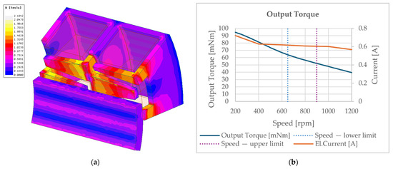
Figure 12.
Simulation of the magnetic flux density (a) led to the final torque output (b). Across the 650–900 rpm speed range, the torque demonstrates an adequate margin to satisfy the requirement of 600,000 actuation cycles.
3.4.2. Optimization of the Lead Screw–Nut Assembly
Motor torque can be converted into linear force using magnetic, ball screw, or lead screw transmission mechanisms, as explained below in Table 5:

Table 5.
Comparison of transmission screw types (magnetic, lead, and ball) according to different features (e.g. efficiency, precision, etc).
- Magnetic transmission systems offer frictionless, non-contact transfer with sub-micrometer positioning and high efficiency [76]. They outperform ball and lead screws in terms of lifetime, noise, backlash elimination, and thermal stability. However, their magnetic components are overly sensitive to manufacturing tolerances, which affects flux distribution and reduces load capacity [77]. The load capacity can be improved with stronger magnetic materials and optimized geometry, but at an excessive cost.
- Ball screws are a more economical alternative to magnetic screws. They are characterized by high efficiency, moderate precision, and greater load capacity. The drawbacks include backlash, wear of balls, absence of self-locking, and reliance on lubricants.
Despite the advantages of magnetic and ball screw transmission mechanisms, the lead screw–nut pair remains the preferred solution in automotive applications due to its compact design, cost-effectiveness, and inherent self-locking capability. The adequate torque-to-force conversion depends on a combination of factors: screw geometry, material, kinematics, manufacturing quality, and friction. When optimized holistically and verified through testing, lead screws can achieve a favorable balance of performance, efficiency, and longevity.
KISSsoft (version 03/2014) is the software used for refining the sliding speed, buckling resistance, and load distribution, which are critical for reducing wear mechanisms, including adhesive, abrasive, and corrosive damage [78]. Especially critical is the wear of the nut, which increases if dynamic loading rates increase [79]. These can cause friction-induced heating and self-excited vibrations, which lead to excessive noise and instability [80]. Predictive models using deep neural networks (DNNs) can identify the instability conditions based on process parameters, where manufacturing tolerances of the whirl milling process remain critical. This can be mitigated with costly inline tool deviation correction techniques [81]. The final result depends on the interaction between the lead screw and nut, material selection, system eigenvalues, the number of tightening and loosening cycles, speed, acceleration, applied load, level of backlash prevention [82], and lubrication state, which is categorized as “dry or lubricated” [83]. Our simulation for lead screw–nut assembly did not include DNNs or other algorithms, but rather the calculation of the worst-case scenario (the “worn/dry” condition shown in Figure 13), backed with DoE tribological pin-on-disc analysis (see Table 6).
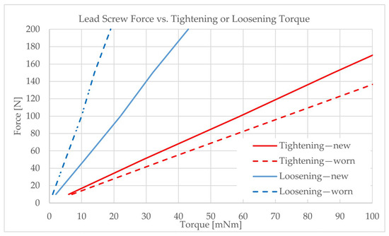
Figure 13.
Lead screw optimization is utilized to maximize linear push and holding force with maximum contribution to the self-locking function.

Table 6.
Pin-on-disc tribological experiments of the lead screw–nut interface and lubricant combination samples.
The results showed the average tightening (actuation) torque above 50 mN·m mN·m and force greater than 67 N in the range of operating speed, which is sufficient for the lifetime requirement.
3.4.3. Control Selection
Control techniques critically affect torque output, dynamic performance, and overall system reliability. These methods are typically classified as either open-loop or closed-loop control:
- Closed-Loop Control systems use encoders or resolvers for real-time feedback, i.e., actively correcting deviations in position, speed, or torque. They offer greater robustness against load disturbances and are preferred in high-precision applications. Hybrid approaches, such as sensorless feedback via back-EMF, offer a balance between complexity and performance.
- Open-Loop Control is cost-effective and simple, relying on predefined pulse sequences to energize motor windings without real-time feedback. It is suitable for low-load, low-precision applications where step accuracy can be assumed.
Control modes include full-step, half-step, and microstepping options:
- Full-step energizes two phases simultaneously, ensuring stability but offering limited resolution and reduced torque at high speeds.
- Half-step alternates between one and two-phase activations, increasing resolution at the expense of smoothness.
- Microstepping divides each full step into finer increments, improving accuracy and minimizing vibration and acoustic noise. However, it requires more complex and costly electronics and may reduce torque.
To prevent step losses under dynamic conditions, techniques such as variable-frequency drive control [84] and adaptive current controllers [85] are recommended. Sensorless methods like PWM-based control [86] and back-EMF observers [87] can also enhance torque availability without increasing system complexity. For higher smoothness and precision, an improved segmented S-shaped correction fitting curve is advised [88] with the combination of soft balanced phase voltage [89], PWM, or a disturbance observer [90]. While proportional–integral (PI) controllers are adequate for moderate demands [91], high-performance applications benefit from advanced methods, such as the following:
- Kalman filters for noise suppression and state estimation [92].
- Space vector PWM for smooth high-frequency commutation [93].
- Model predictive control and adaptive fuzzy systems for managing nonlinear dynamics and external disturbances [94,95].
- Algorithms for multi-mode operation balancing torque and precision, using neural networks [96], adapting control time with load or current angles [97], and applying a minimum energy consumption approach using nonlinear FEA [98]. More about algorithms can be found in [99].
As automotive applications are under intense cost pressure, a low-cost open-loop approach is selected. It uses Hall-effect sensors for end-stop detection and a trapezoidal motion profile for smoother transitions. This configuration must be verified within the samples and test equipment to offer sufficient positioning reliability, precision, and torque while maintaining system cost and complexity at minimum acceptable levels. However, mounting precision of Hall-effect sensors is crucial, meaning that electromagnetic simulation and tolerance chain calculations (Figure 14) must be performed in order to ensure the required precision of mounting the sensors onto printed circuit board assemblies (PCBAs).
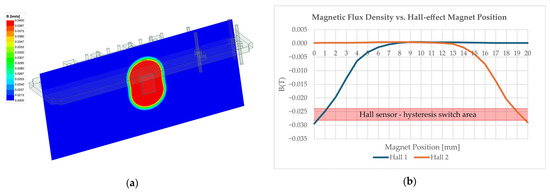
Figure 14.
Simulation in (a) shows the magnetic flux density distribution around the unipolar Hall sensor location, and (b) shows the hysteresis area for switching between ON/OFF states.
The switching values (−0.0282 T and −0.0239 T) of the Hall sensor are based on the manufacturer’s information. Based on the simulation, this determines the location of both sensors compared to the magnet position (Hall 1 from 0.3 mm to 1.2 mm and Hall 2 from 18.8 mm to 19.7 mm). Statistically, positioning Hall sensors during the PCBA manufacturing process does not represent an issue, as the process capability index Cpk is 1.75 (N = 96 samples), which is above the required 5-sigma Cpk level of 1.67.
3.5. System Integration and Final Validation
After all components and their design factors are determined, the EMLA is integrated into the system and validated. System integration and final validation are often performed separately; however, in our case, a seamless combination of both ensures that EMLAs are validated under the specified environmental and operational conditions, enabling efficient traceability and confirming that the EMLA meets system-level requirements. The final validation is performed through adequate reliability assessment, including validation tests, and nonlinear effects are evaluated based on force loss determination.
3.5.1. Reliability Assessment
The reliability strategy must ensure consistent and long-term performance under harsh environmental and operational conditions. The main goal is to minimize the occurrence of failure by achieving system- and component-level robustness. This can be achieved with design-related enhancements, redundancy, fault detection, condition monitoring, prediction modeling, and quality assurance. In the presented case, redundancy and system diagnostics with predictive maintenance are not applicable due to the requirement of cost-efficiency. Therefore, the main goal is to improve the design by setting reliability objectives, identifying failure risks (e.g., FMEA), and performing reliability predictions based on verification loops consisting of accelerated experiments, physics-of-failure, or reliability block diagrams.
The most critical failure-prone components of the selected EMLA are ball bearings and the lead screw–nut pair with applied lubricant, while the robustness of other components is already assured in early design stages. According to [100], bearings mostly fail due to excessive wear, corrosion, contamination, lubricant degradation, misalignment [101], internal clearance [102], preload [103], and overloading [104]. Materials like hybrid ceramics with low-friction coating [105] or improved surface finish of ball and raceway curvature could extend the product lifetime [106], but at a great cost. Therefore, fault detection and condition monitoring are advised instead. Local defects manifest as modulation in vibration signals [107], where fault isolation in noisy environments could be enhanced with artificial intelligence [108]. Bearing degradation prediction uses statistical life models like Weibull and maximum entropy distributions [109], physics-informed artificial intelligence [110], and hybrid models for small datasets [111]. Despite monitoring and failure prediction, consistent manufacturing shall be ensured. Either by bootstrapped reliability analysis of robustness under limited data [112], end-of-line vibration tests to identify defective bearings [113], or wear characterization via noise and lubricant monitoring [114].
Our case is focused on ensuring reliability and maximal EMLA linear push force by selecting the adequate lubricant type in ball bearings and an optimal combination of lead screw–nut and lubricant. The main goal is to directly lower the friction levels and degradation of material, affecting torque or force losses. The optimal lubricant to achieve the lowest torque losses across the complete temperature range from −40 °C to +150 °C is determined by the supplier’s experimentally supported calculator (Figure 15).
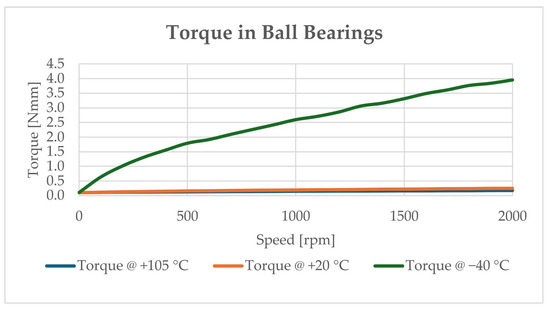
Figure 15.
Optimal bearing lubrication ensures the lowest torque losses.
The most crucial components in terms of reliability are the lead screw, nut, and lubricant applied to both. The combined interface significantly impacts the efficiency of transferring motor torque to linear force and the lifetime of the actuator. The interface experiences mechanical wear, friction, and potential dynamic instability. Key effects are fatigue and unwanted accelerated wear due to uneven load distribution across threads [115], thermal-induced backlash, and transverse or torsional vibrations with increased noise levels [116]. These risks are mitigated through an adequate selection of materials, manufacturing quality assurance, interdisciplinary wear, and fatigue life modeling [78], or by using costly magnetic lead screws, which eliminate contact between the nut and the screw [77]. The lubricants are either based on mineral, synthetic, or semi-synthetic base oils. Their viscosity, high-load resistance, oxidation, and thermal stability are altered with different additives. However, exposure to a wide range of temperatures from −40 °C to +105 °C and the presence of contaminants (moisture, dust, and metal particles) can accelerate oxidative degradation, resulting in higher friction and wear of the lead screw–nut interface.
The amount of wear, the wear factor, and the change in axial play were evaluated through a case study with the aim of selecting the optimal combination of the materials used in the lead screw, the nut, and the lubricant in order to reach the reliability requirements. The test results of pin-on-disc tests simulating 600,000 actuations and conditions inside the lead screw–nut assembly are shown in Table 7, Figure 16. The minimum material wear and change in axial play are achieved with a stainless steel 1.4305 lead screw, special grade CuZn31Mn2SiAl nut material, and high-performance lubricant based on PFPE base oil with PTFE thickener (see sample combination in Table 6).

Table 7.
Pin-on-disc tribological experiments of the lead screw–nut interface and lubricant combination (mean and standard deviation (STDEV) results).
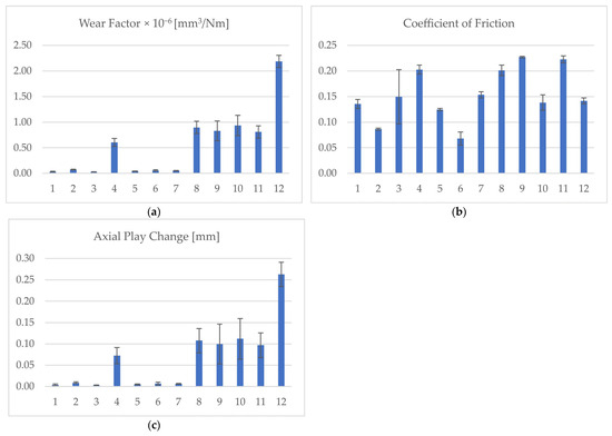
Figure 16.
Graphs show mean and standard deviation values for (a) wear factor, (b) coefficient of friction (CoF), and (c) axial play change for 12 different material combinations of lead screw–nut assembly and lubrication.
Based on an extensive tribological analysis performed at 25 °C, it can be concluded that the lowest wear factor and the lowest axial play change are observed in sample group 3. Although the sample size is three samples per group, the observed mean values differ significantly, providing sufficient confidence that sample group 3 represents the tribologically optimal solution and should therefore be employed in accelerated lifecycle tests. The results are used within a feedback loop to improve the analytical and numerical models.
The accelerated lifecycle tests were performed to confirm the EMLA configuration of the highest motor torque and the lowest torque losses in the bearings and in the lead screw–nut interface, as well as the use of high-performance lubricant. The most critical parameters are mechanical endurance and thermal cycling tests, which exhibit reliability issues in terms of not reaching the minimum push force of 40 N. In mechanical endurance tests (constant +105 °C, 600,000 actuation cycles), EMLAs fail after 500,000 actuations (Figure 17), while in thermal cycling tests (six temperature cycles, 97.38 h each, cycling from −40 °C to +105 °C and back), EMLAs fail to deliver 40 N in the subzero temperature range. The failures do not indicate a shortcoming of the methodology itself but highlight the need for improved material life models and lubricant aging considerations in the design loop. In future work, integrating these into the iterative framework will further improve lifetime prediction accuracy.
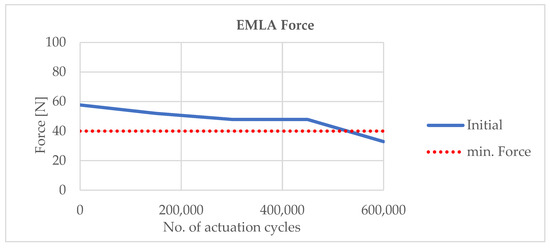
Figure 17.
Initial mechanical endurance test at the maximum specified ambient temperature showed that EMLAs run at 880 Hz (880 steps/s) did not ensure a min. force of 40 N throughout the lifecycle.
Based on the proposed methodology with feedback loops, a review of the requirements, concept, and detailed design is needed prior to using targeted physical experiments for excessive force loss root causes.
3.5.2. Force Loss Determination Experiments
The force loss is detected during the experimental testing and represents a discrepancy between simulated and measured results. The design methodology steps could include infinite design updates and verification tests; however, the proposed methodology included force loss analysis of several potential root causes, such as the following:
- Idealized Lead Screw–Nut Contact Assumptions: Calculations assumed an ideal lead screw–nut contact without micro-slipping or misalignment. In practice, thread friction varies due to surface roughness, wear, and manufacturing tolerances.
- Neglected Lubrication Effects: Temperature-dependent grease viscosity changes, which drastically affect torque. These effects are impossible to address in the thermal-electromechanical model without physical experimentation.
- Dynamic Stiffness and Compliance: Structural elements between the housing and the slider exhibit higher friction under load, altering force paths. Simulations modeled these as rigid parts.
- Friction Nonlinearity and Preload Variation: Frictional losses are not constant and are underestimated in steady-state models. Variation in preload due to assembly tolerances led to further discrepancies.
- Subharmonic Resonances: At a driving speed of 880 Hz, subharmonic resonances can occur that reduce effective force output. These nonlinear dynamic effects are not represented in FEA or analytical models.
- Experiment Summary:
- Tests were performed on a suspended actuator using a two-way load setup (Figure 18) with applied moment (Figure 19), and applied side forces (Figure 20).
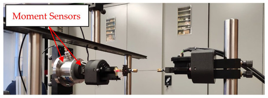 Figure 18. Suspended EMLA with attached moment sensors (X, Y, and Z).
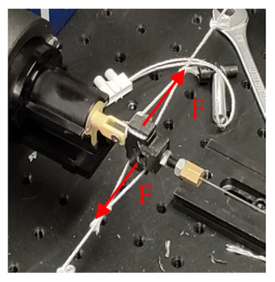 Figure 19. Moment applied to the EMLA.
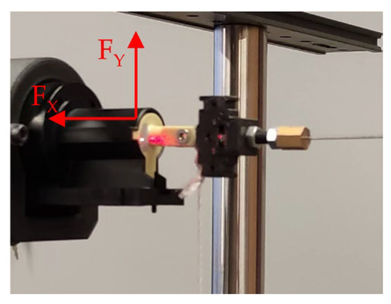 Figure 20. Side force applied to the EMLA.
 - Friction varied via a mechanical adjustment bolt at various actuator speeds of 440, 660, and 880 Hz.
- Sensors captured axial push/pull forces at varying friction levels and side loads (X/Y directions).
- The measurements detected an influence of ramp settings and low temperatures (−30 °C to −40 °C).
- Key Results of Force Loss Tests:
- Friction force is increased due to tighter slider–housing interaction and bearing lubricant viscosity at low temperatures, but it does not have a significant influence on maximum push force.
- Tighter tolerances and improved surface roughness of lead screw–nut threads do not significantly improve the push force.
- Subzero temperatures reduce force in the range of 30%, due to increased lubricant viscosity despite using a high-performance lubricant (Figure 21). Some of the measurements are performed at slightly different subzero temperatures due to practical test bench constraints, introducing small deviations in nut friction due to lubricant viscosity and material contraction. The theoretical curve remains valid as the overall trend is preserved.
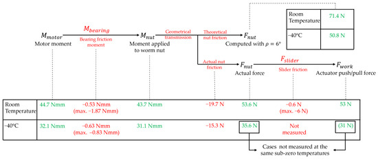 Figure 21. Force loss breakdown exhibits a significant force difference in actuations at room temperature and −40 °C.
 - Different speed ramps from 3 to 13 Hz/ms at constant driving frequency have little effect on maximum force (worst at 13 Hz/ms and best in the range of 9–11 Hz/ms).
- A considerable number of natural frequencies are detected in the range of 880 Hz driving frequency (Figure 22). Three subharmonics emerged at 220 Hz, 440 Hz, and 660 Hz (Figure 23). During operation, vibrations in the range of natural frequencies cause excessive wear, step losses, lower push force, and failure during lifetime tests. Therefore, it is essential to avoid these ranges by lowering the driving frequency to between 660 Hz and 880 Hz. Increasing the frequency over 880 Hz is not possible due to a motor torque curve drop, while decreasing the frequency increases the EMLA force. The optimal level of new driving frequency of 690 Hz is determined by reviewing other key requirements, such as time and speed of actuation.
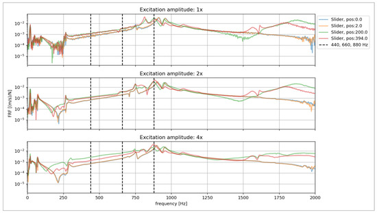 Figure 22. A considerable number of natural frequencies were detected.
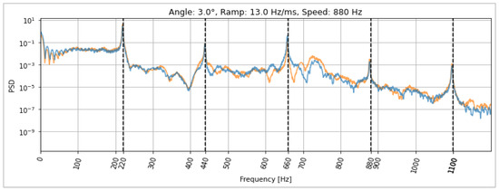 Figure 23. Three subharmonics of 880 Hz driving frequency are the cause of performance issues.
4. Results and Discussion
This study demonstrates the advantages of a hybrid actuator development methodology that combines Analytical Modeling, FEA, GA-based optimization, control, reliability assessment, and short verification loops in each step, with the following key considerations:
- Performance Enhancement through Optimization
The GA-augmented electromagnetic FEA significantly improves torque density by optimizing claw-pole and magnetic path geometry. Unlike traditional empirical design or look-up-based motor sizing, this method explores non-intuitive design solutions while respecting manufacturing constraints. The result is a quantifiable increase in torque output and energy efficiency under constrained current limits.
- Trade-offs and Integration Benefits
By jointly optimizing the motor and mechanical transmission, the design ensured a balance between force delivery, self-locking functions, and compactness. This systemic approach avoided over-design in any sub-system and enabled a modular actuator package suitable for automotive constraints such as noise (<40 dB), vibration, and ISO 26262 compliance.
- Control Strategy Justification
The decision to retain an open-loop drive with Hall sensor end-stop detection was validated against application needs. Although closed-loop control can improve dynamic response, the added complexity, cost, and wiring would outweigh the benefits in this short-stroke, low-speed application. The trapezoidal motion profile further enhanced smoothness without inducing excessive stress.
- Reliability Assessment
Physical wear factors (e.g., screw friction) were modeled analytically and supported by design-of-experiments data. The components are designed to achieve the highest possible performance before introducing physical experimentation. Consequently, loops of experiments and rework are decreased while reliability confidence is increased.
- Comparison to Conventional Design Methods
The proposed methodology was compared with the sequential design method (CAD-FEA iterations, MBD, and late-stage prototype testing) by two separate design teams. The sequential approach needs more than seven months of design iterations, and it is unable to accurately model nonlinear effects without numerous physical experiments. Alternatively, the proposed hybrid approach reduced development time by ~30% by enabling early-stage decisions based on physics-informed modeling, avoiding reliance on oversimplified safety factors and eliminating typical convergence or rework issues, thereby leading to significant material and labor cost savings.
- Final Design Improvements
Improving the lead screw–nut interface (surface roughness, geometry, and quality of threads) by decreasing the driving frequency from 880 Hz to 690 Hz significantly increased the push force (Figure 24).
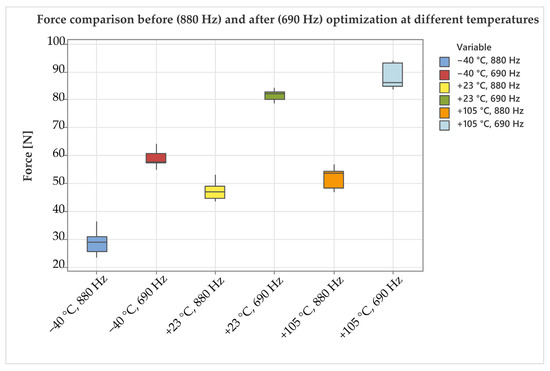
Figure 24.
Force comparison before and after optimization showed a significant increase in EMLA force, reaching more than 40 N across the complete temperature range from −40 °C to +105 °C.
In repeated validation tests, a higher overall push force enabled the EMLA to reach more than 40 N over the complete lifetime of 600,000 actuations (Figure 25) and a sufficiently high push force in the subzero temperature range.
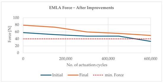
Figure 25.
Final optimization ensured the required lifetime of 600,000 actuation cycles.
5. Conclusions
This paper presents a comprehensive hybrid design methodology that successfully addresses the complex requirements of EMLAs in demanding automotive environments. The integration of Analytical Modeling, FEA simulations, GA-based optimization, and targeted physical experiments for force loss determination has proven to be a highly effective approach for achieving both high-performance and long-term reliability. The methodology, with included verification feedback loops, enables the development of an actuator that exceeds critical performance requirements, namely output push force greater than 40 N and a lifetime of over 600,000 actuations, while simultaneously delivering significant reductions in design time and costs. These outcomes demonstrate the value of a multidisciplinary optimization framework, particularly in high-precision and reliability-critical applications. While the novelty primarily lies in the strategic integration of well-established techniques, the research makes a clear and practical contribution to the applied sciences or the field of actuator design. By validating the methodology through an automotive case study, this work sets a precedent for broader adoption in related engineering domains. Future work should aim to generalize the methodology across other actuator types and applications, incorporate more advanced optimization techniques, and increase the depth of experimental validation.
Author Contributions
M.Đ.: conceptualization, methodology, research, tests, writing—original draft. D.B.: writing—review and editing, validation. L.S.: data processing, validation. All authors have read and agreed to the published version of the manuscript.
Funding
This research was funded by Iskra Mehanizmi d.o.o. and ARIS P2-0270 Production systems, laser technologies, and material joining.
Data Availability Statement
The data supporting this study is available on-site at Iskra Mehanizmi d.o.o. and can be provided upon request.
Acknowledgments
During the preparation of this study, the author(s) used different tools and reviewed and edited the output. The authors take full responsibility for the content of this publication.
Conflicts of Interest
The authors declare no conflicts of interest.
Abbreviations
The following abbreviations are used in this manuscript:
| Abbreviation | Full Name |
| AI | Artificial Intelligence |
| ASIL-B | Automotive Safety Integrity Level B |
| BEMF | Back Electromotive Force |
| BEV | Battery Electric Vehicle |
| CAD | Computer-Aided Design |
| CO2 | Carbon Dioxide |
| CoF | Coefficient of Friction |
| Cpk | Process Capability Index |
| DE | Differential Evolution |
| DfX | Design for X (where X can be Reliability, Manufacturability, Safety, …) |
| DNN | Deep Neural Network |
| DoE | Design of Experiments |
| EMF | Electromotive Force |
| EMLA | Electromechanical Linear Actuator |
| FEA | Finite Element Analysis |
| FMEA | Failure Mode and Effects Analysis |
| FTA | Fault Tree Analysis |
| GA | Genetic Algorithm |
| H-SM | Hybrid Stepper Motor |
| LED | Light-Emitting Diode |
| MBD | Model-Based Design |
| ML | Machine Learning |
| MOO | Multi-Objective Optimization |
| MPC | Model Predictive Control |
| NSGA-II | Non-dominated Sorting Genetic Algorithm II |
| PCBA | Printed Circuit Board Assembly |
| PI | Proportional–Integral (controller) |
| PM-SM | Permanent Magnet Stepper Motor |
| ppm | Parts Per Million |
| PSO | Particle Swarm Optimization |
| PWM | Pulse-Width Modulation |
| REQs | Requirements |
| rpm | Revolutions per minute (used for easier indication in motors) |
| RSM | Response Surface Methodology |
| SOO | Single-Objective Optimization |
| STDEV | Standard Deviation |
| SVPWM | Space Vector Pulse-Width Modulation |
| VR-SM | Variable Reluctance Stepper Motor |
References
- Lyu, P.; Wang, S.; Liu, Y.; Wang, Y. Review of the Studies on Emission Evaluation Approaches for Operating Vehicles. J. Traffic Transp. Eng. (Engl. Ed.) 2021, 8, 493–509. [Google Scholar] [CrossRef]
- Forster, P.M.; Smith, C.; Walsh, T.; Lamb, W.F.; Lamboll, R.; Cassou, C.; Hauser, M.; Hausfather, Z.; Lee, J.-Y.; Palmer, M.D.; et al. Indicators of Global Climate Change 2024: Annual Update of Key Indicators of the State of the Climate System and Human Influence. Earth Syst. Sci. Data 2025, 17, 2641–2680. [Google Scholar] [CrossRef]
- Lequesne, B. Automotive Electrification: The Nonhybrid Story. IEEE Trans. Transp. Electrif. 2015, 1, 40–53. [Google Scholar] [CrossRef]
- Jain, T.; Bdy, S.; Hasan, M.; Jain, A.; B, S.; Chahuan, N. Smart Materials for Sensing and Actuation: State-of-the-Art and Prospects. E3S Web Conf. 2024, 505, 01034. [Google Scholar] [CrossRef]
- Di Gaeta, A.; Montanaro, U.; Giglio, V. Modelling and Cycle-by-Cycle Control of an Electromechanical Engine Valve Actuator with Impact Speed Limiter Based on Hydraulic Damper. Asian J. Control. 2024, 26, 2278–2296. [Google Scholar] [CrossRef]
- Temporelli, R.; Boisvert, M.; Micheau, P. Control of an Electromechanical Clutch Actuator Using a Dual Sliding Mode Controller: Theory and Experimental Investigations. IEEE/ASME Trans. Mechatron. 2019, 24, 1674–1685. [Google Scholar] [CrossRef]
- Klimenko, Y.I.; Batishchev, D.V.; Pavlenko, A.V.; Grinchenkov, V.P. Design of a Linear Electromechanical Actuator with an Active Vehicle Suspension System. Russ. Electr. Eng. 2015, 86, 588–593. [Google Scholar] [CrossRef]
- Kocabicak, Z.; Demir, U. Design and Optimization of an Electromechanical Actuator for the Latch of a Foldable Vehicle Seat. Mater. Test. 2020, 62, 749–755. [Google Scholar] [CrossRef]
- Kim, H.; Kim, J.; Han, K.; Won, D. 1D Modeling Considering Noise and Vibration of Vehicle Window Brushed DC Motor. Appl. Sci. 2022, 12, 11405. [Google Scholar] [CrossRef]
- Wu, J.; Zhang, H.; He, R.; Chen, P.; Chen, H. A Mechatronic Brake Booster for Electric Vehicles: Design, Control, and Experiment. IEEE Trans. Veh. Technol. 2020, 69, 7040–7053. [Google Scholar] [CrossRef]
- Lee, C.; Lim, M.; Kim, C.; Bae, S.J. Reliability Analysis of Accelerated Destructive Degradation Testing Data for Bi-Functional DC Motor Systems. Appl. Sci. 2021, 11, 2537. [Google Scholar] [CrossRef]
- Le, H.M.; Do, T.N.; Phee, S.J. A Survey on Actuators-Driven Surgical Robots. Sens. Actuators A Phys. 2016, 247, 323–354. [Google Scholar] [CrossRef]
- Yi, F.; Zhang, C.; Chen, S.; Qiu, S.; Zhang, H.; Du, Q.; Wang, W.; Yang, G. A Compact Actuator for Lower-Limb Exoskeletons with High Torque Density and High Backdrivability. IEEE/ASME Trans. Mechatron. 2025, 30, 1–12. [Google Scholar] [CrossRef]
- Kończak, M.; Kukla, M.; Warguła, Ł.; Rybarczyk, D.; Wieczorek, B. Considerations for the Design of a Wheelchair Dynamometer Concerning a Dedicated Braking System. Appl. Sci. 2023, 13, 7447. [Google Scholar] [CrossRef]
- Hermawan, S.; Rochardjo, H. Preliminary Design of Electric Linear Actuator for Hospital Bed Domestic Product. J. Mech. Des. Test. 2022, 4, 25. [Google Scholar] [CrossRef]
- Pravika, M.; Jacob, J.; Paul Joseph, K. Design of Linear Electromechanical Actuator for Automatic Ambulatory Duodopa Pump. Eng. Sci. Technol. Int. J. 2022, 31, 101056. [Google Scholar] [CrossRef]
- Fedosovsky, M.E.; Uvarov, M.M.; Aleksanin, S.A.; Pyrkin, A.A.; Colombo, A.W.; Prattichizzo, D. Sustainable Hyperautomation in High-Tech Manufacturing Industries: A Case of Linear Electromechanical Actuators. IEEE Access 2022, 10, 98204–98219. [Google Scholar] [CrossRef]
- Mohammed, M.J.; Mat Darus, I.Z.; Shaharuddin, N.M.R.; AL-Khafaji, A.A.M. Open Loop Active Control Technique on Segmented Marine Riser Vibration Using Electromechanical Actuator. Iran. J. Sci. Technol. Trans. Mech. Eng. 2019, 43, 799–813. [Google Scholar] [CrossRef]
- Bertolino, A.C.; De Martin, A.; Jacazio, G.; Sorli, M. Design and Preliminary Performance Assessment of a PHM System for Electromechanical Flight Control Actuators. Aerospace 2023, 10, 335. [Google Scholar] [CrossRef]
- Malik, S.; Shafqat, W.; Lee, K.-T.; Kim, D.-H. A Feature Selection-Based Predictive-Learning Framework for Optimal Actuator Control in Smart Homes. Actuators 2021, 10, 84. [Google Scholar] [CrossRef]
- Redekar, A.; Deb, D.; Ozana, S. Functionality Analysis of Electric Actuators in Renewable Energy Systems—A Review. Sensors 2022, 22, 4273. [Google Scholar] [CrossRef]
- Qiao, G.; Liu, G.; Shi, Z.; Wang, Y.; Ma, S.; Lim, T. A Review of Electromechanical Actuators for More/All Electric Aircraft Systems. Proc. Inst. Mech. Eng. Part C J. Mech. Eng. Sci. 2017, 232, 4128–4151. [Google Scholar] [CrossRef]
- Yin, Z.; Neil, H.; Chen, J.; Yang, Y.; Shen, G. A Review of Fault Diagnosis, Prognosis and Health Management for Aircraft Electromechanical Actuators. IET Electr. Power Appl. 2022, 16, 1249–1272. [Google Scholar] [CrossRef]
- Budinger, M.; Reysset, A.; Halabi, T.E.; Vasiliu, C.; Maré, J.-C. Optimal Preliminary Design of Electromechanical Actuators. Proc. Inst. Mech. Eng. Part G J. Aerosp. Eng. 2014, 228, 1598–1616. [Google Scholar] [CrossRef]
- Budinger, M.; Liscouët, J.; Hospital, F.; Maré, J.-C. Estimation Models for the Preliminary Design of Electromechanical Actuators. Proc. Inst. Mech. Eng. Part G J. Aerosp. Eng. 2012, 226, 243–259. [Google Scholar] [CrossRef]
- Miroschnitschenko, B.; Amrhein, W.; Poltschak, F. Design and Optimization of a Linear-Rotary Electromagnetic Actuator Based on Analytical Model of Magnetic Flux. In Proceedings of the 2024 International Symposium on Power Electronics, Electrical Drives, Automation and Motion (SPEEDAM), Napoli, Italy, 19–21 June 2024; pp. 1002–1009. [Google Scholar] [CrossRef]
- Liu, C.; Chau, K.T.; Lee, C.H.T.; Song, Z. A Critical Review of Advanced Electric Machines and Control Strategies for Electric Vehicles. Proc. IEEE 2021, 109, 1004–1028. [Google Scholar] [CrossRef]
- Figueroa, A.; Lin, Y. Design and Prototyping of a Linear Electromechanical Actuator. Appl. Mech. Mater. 2011, 110–116, 4951–4961. [Google Scholar] [CrossRef]
- Di Gaeta, A.; Glielmo, L.; Giglio, V.; Police, G. Modeling of an Electromechanical Engine Valve Actuator Based on a Hybrid Analytical-FEM Approach. IEEE/ASME Trans. Mechatron. 2008, 13, 625–637. [Google Scholar] [CrossRef]
- Stuebig, C.; Ponick, B. Comparison of Calculation Methods for Hybrid Stepping Motors. IEEE Trans. Ind. Appl. 2012, 48, 2182–2189. [Google Scholar] [CrossRef]
- Barbieri, G.; Fantuzzi, C.; Borsari, R. A Model-Based Design Methodology for the Development of Mechatronic Systems. Mechatronics 2014, 24, 833–843. [Google Scholar] [CrossRef]
- Hucko, S.; Matthiesen, G.; Reinertz, O.; Schmitz, K. Investigation of Magnetic Force Hysteresis in Electromechanical Actuators. Chem. Eng. Technol. 2023, 46, 158–166. [Google Scholar] [CrossRef]
- Maré, J.-C. Friction Modelling and Simulation at System Level: Considerations to Load and Temperature Effects. Proc. Inst. Mech. Eng. Part I J. Syst. Control. Eng. 2015, 229, 27–48. [Google Scholar] [CrossRef]
- Kebairi, A.; Becherif, M.; El Bagdouri, M. Modelling, Simulation, and Identification of an Engine Air Path Electromechanical Actuator. Control Eng. Pract. 2015, 34, 88–97. [Google Scholar] [CrossRef]
- Maré, J.-C. Practical Considerations in the Modelling and Simulation of Electromechanical Actuators. Actuators 2020, 9, 94. [Google Scholar] [CrossRef]
- Ahmed, F.S.; Laghrouche, S.; El Bagdouri, M. Overview of the Modelling Techniques of Actuator Non-Linearities in the Engine Air Path. Proc. Inst. Mech. Eng. Part D J. Automob. Eng. 2013, 227, 443–454. [Google Scholar] [CrossRef]
- Wang, J.; Zhang, Y.; Luo, C.; Miao, Q. Deep Learning Domain Adaptation for Electro-Mechanical Actuator Fault Diagnosis Under Variable Driving Waveforms. IEEE Sens. J. 2022, 22, 10783–10793. [Google Scholar] [CrossRef]
- Li, H. Nonlinear Control Method of Electromechanical Actuator Using Genetic Algorithm. Int. J. Mechatron. Appl. Mech. 2020, I, 182–189. [Google Scholar]
- Veresnikov, G.S.; Bazhenov, S.G.; Bashkirov, I.G.; Chernyshev, S.L.; Goncharenko, V.I.; Skryabin, A.V.; Petrov, D.A. Machine Learning-Based Synthesis of Diagnostic Algorithms for Electromechanical Actuators to Improve the Aerospace Flight Safety. Acta Astronaut. 2025, 226, 239–247. [Google Scholar] [CrossRef]
- Juniani, A.I.; Singgih, M.L.; Karningsih, P.D. Design for Manufacturing, Assembly, and Reliability: An Integrated Framework for Product Redesign and Innovation. Designs 2022, 6, 88. [Google Scholar] [CrossRef]
- Graessler, I.; Hentze, J. The New V-Model of VDI 2206 and Its Validation. Automatisierungstechnik 2020, 68, 312–324. [Google Scholar] [CrossRef]
- Liu, B.; Zhang, H.; Zhu, S. An Incremental V-Model Process for Automotive Development. In Proceedings of the 2016 23rd Asia-Pacific Software Engineering Conference (APSEC), Hamilton, New Zealand, 6–9 December 2016; pp. 225–232. [Google Scholar] [CrossRef]
- Deuter, A. Slicing the V-Model—Reduced Effort, Higher Flexibility. In Proceedings of the 2013 IEEE 8th International Conference on Global Software Engineering, Bari, Italy, 26–29 August 2013; pp. 1–10. [Google Scholar] [CrossRef]
- Liu, P.S.; Chin, J.F.; Ab-Samat, H.; Xie, Z.P. Digital Variant Design V-Model for Rapid Product Development. Int. J. Adv. Manuf. Technol. 2025, 139, 2103–2121. [Google Scholar] [CrossRef]
- Ullrich, L.; Buchholz, M.; Dietmayer, K.; Graichen, K. Expanding the Classical V-Model for the Development of Complex Systems Incorporating AI. IEEE Trans. Intell. Veh. 2025, 10, 1790–1804. [Google Scholar] [CrossRef]
- DIN ISO 2768-1; General Tolerances—Part 1: Tolerances for Linear and Angular Dimensions Without Individual Tolerance Indications. Deutsches Institut für Normung (DIN): Berlin, Germany, 1991.
- ISO 16750-3; Road Vehicles—Environmental Conditions and Testing for Electrical and Electronic Equipment—Part 3: Mechanical Loads. International Organization for Standardization (ISO): Geneva, Switzerland, 2023.
- ISO 16750-2; Road Vehicles—Environmental Conditions and Testing for Electrical and Electronic Equipment—Part 2: Electrical Loads. International Organization for Standardization (ISO): Geneva, Switzerland, 2023.
- DIN EN 60034-1; Rotating Electrical Machines—Part 1: Rating and Performance. Deutsches Institut für Normung (DIN): Berlin, Germany; International Electrotechnical Commission (IEC): Geneva, Switzerland, 2011.
- VW 80101; General Test Conditions for Electrical, Electromechanical, and Electronic Assemblies in Motor Vehicles. Volkswagen AG: Wolfsburg, Germany, 2009.
- ISO 16750-4; Road Vehicles—Environmental Conditions and Testing for Electrical and Electronic Equipment—Part 4: Climatic Loads. International Organization for Standardization (ISO): Geneva, Switzerland, 2023.
- ISO 3744; Acoustics—Determination of Sound Power Levels of Noise Sources Using Sound Pressure—Engineering Method in an Essentially Free Field over a Reflecting Plane. International Organization for Standardization (ISO): Geneva, Switzerland, 2010.
- ISO 16750-5; Road Vehicles—Environmental Conditions and Testing for Electrical and Electronic Equipment—Part 5: Chemical Loads. International Organization for Standardization (ISO): Geneva, Switzerland, 2023.
- IATF 16949; Quality Management System Requirements for Automotive Production and Relevant Service Parts Organizations. International Automotive Task Force (IATF): Torino, Italy, 2016.
- IEC 60034-14; Rotating Electrical Machines—Part 14: Mechanical Vibration of Certain Machines with Shaft Heights 56 mm and Higher—Measurement, Evaluation and Limits of Vibration Severity. International Electrotechnical Commission (IEC): Geneva, Switzerland, 2018.
- ISO 26262; Road Vehicles—Functional Safety. International Organization for Standardization (ISO): Geneva, Switzerland, 2018.
- Lu, B.; Xu, Y.; Ma, X. Design and Analysis of a Novel Stator-Permanent-Magnet Hybrid Stepping Motor. IEEE Trans. Appl. Supercond. 2016, 26, 0607705. [Google Scholar] [CrossRef]
- Acarnley, P. Stepping Motors: A Guide to Theory and Practice; IET: London, UK, 2002. [Google Scholar]
- Rajagopal, K.R.; Singh, B.; Singh, B.P. Optimal Tooth-Geometry for Specific Performance Requirements of a Hybrid Stepper Motor. IEEE Trans. Magn. 2003, 39, 3010–3012. [Google Scholar] [CrossRef]
- Hojati, M.; Baktash, A.; Jabbari, A.; Soury, E. An Improved Structure for Hybrid Stepper Motors to Increase the Torque Density. Iran. J. Sci. Technol. Trans. Electr. Eng. 2022, 46, 1223–1232. [Google Scholar] [CrossRef]
- Hojati, M.; Baktash, A. Design and Fabrication of a New Hybrid Stepper Motor with Significant Improvements in Torque Density. Eng. Sci. Technol. Int. J. 2021, 24, 1116–1122. [Google Scholar] [CrossRef]
- Rajagopal, K.R.; Singh, B.; Singh, B.P.; Murthy, S.S. Torque Saturation, and Inherent Temperature Compensation of Hybrid Stepper Motor Used in Space Application. J. Appl. Phys. 2002, 91, 6964–6966. [Google Scholar] [CrossRef]
- Hojati, M.; Baktash, A. Hybrid Stepper Motor with Two Rows of Teeth on a Cup-Shaped Rotor and a Two-Part Stator. Precis. Eng. 2022, 73, 228–233. [Google Scholar] [CrossRef]
- Teodor-Ionut, I.; Craiu, O.; Popescu, L. Analyzing A Three Hundred Teeth Bi-Phase Hybrid Stepper Motor with Different Numbers of Pole Pairs. Rev. Roum. Sci. Tech. Série Électrotechnique Énergétique 2023, 68, 283–288. [Google Scholar] [CrossRef]
- Pillans, J. Reducing Position Errors by Vibration Optimization of Stepper Motor Drive Waveforms. IEEE Trans. Ind. Electron. 2021, 68, 5176–5183. [Google Scholar] [CrossRef]
- Ionica, I.; Modreanu, M.; Morega, A.; Boboc, C. Numerical Analysis of a Hybrid Stepper Motor for the Electromagnetic Torque Calculation. In Proceedings of the 11th International Symposium on Advanced Topics in Electrical Engineering, Bucharest, Romania, 28–30 March 2019; pp. 1–6. [Google Scholar] [CrossRef]
- Madhavan, R.; Mane, D.U.; Saxena, D. Effect of Multi-Pole Rotor Magnetization on Can-Stack Stepper Linear Actuator Performance. In Proceedings of the 2016 IEEE Annual India Conference (INDICON), Bangalore, India, 16–18 December 2016; pp. 1–5. [Google Scholar] [CrossRef]
- Hojati, M.; Baktash, A.; Mukhopadhyay, S. Investigation of Torque and Sensitivity Analysis of a Two-Phase Hybrid Stepper Motor. Int. J. Smart Sens. Intell. Syst. 2024, 17, 1–21. [Google Scholar] [CrossRef]
- Xin, Y.; Sun, Y.; Wang, X.; Xi, X.; Su, Y.; Yang, Y. Static Torque Analysis of Micro Claw-Pole Stepper Motor Based on Field-Circuit Combination. Micromachines 2022, 13, 1517. [Google Scholar] [CrossRef] [PubMed]
- Xi, X.; Sun, Y.; Wang, X.; Xin, Y.; Yang, Y. A Study on the Detent Torque and Holding Torque of a Micro-Claw Pole Stepper Motor. Micromachines 2022, 13, 931. [Google Scholar] [CrossRef] [PubMed]
- Mariolo, L.; Rubino, A.; Spelta, D.; Frosini, L. Modeling of Hybrid Stepper Motor Finalized to the Optimization of the Holding Torque. In Proceedings of the 2021 IEEE Workshop on Electrical Machines Design, Control and Diagnosis (WEMDCD), Modena, Italy, 27–28 April 2021; pp. 107–112. [Google Scholar] [CrossRef]
- Szewczyk, K.; Koscielniak, A.; Kot, R. Analysis of Magnetic Circuits for a Hybrid Stepper Motor with Cogging Torque Reduction. Prz. Elektrotechniczny 2012, 88, 44–46. [Google Scholar]
- Peng, Z.; Bi, C.; Fang, L.; Xiao, L. Optimization of Three-Phase Hybrid Stepper Motors for Noise Reduction. Sensors 2022, 22, 356. [Google Scholar] [CrossRef]
- Bernat, J.; Kołota, J.; Stępień, S. Minimising of Electromagnetic Torque Ripple of Reluctance Stepper Motor. Przegląd Elektrotechniczny 2012, 88, 200–203. [Google Scholar]
- Arias, A.; Caum, J.; Ibarra, E.; Grino, R. Reducing the Cogging Torque Effects in Hybrid Stepper Machines by Means of Resonant Controllers. IEEE Trans. Ind. Electron. 2019, 66, 2603–2612. [Google Scholar] [CrossRef]
- Lu, K.; Wu, W. Electromagnetic Lead Screw for Potential Wave Energy Application. IEEE Trans. Magn. 2014, 50, 8205004. [Google Scholar] [CrossRef]
- Bahrami Kouhshahi, M.; Bird, J.Z.; Kadel, J.D.; Williams, W.B. Designing and Experimentally Testing a Magnetically Geared Lead Screw. IEEE Trans. Ind. Appl. 2018, 54, 5736–57471. [Google Scholar] [CrossRef]
- Meruva, K.; Bi, Z.; Mueller, D.; Kang, B. Formulation and Validation of Multidisciplinary Design Problem on Wear and Fatigue Life of Lead Screw Actuators. Math. Probl. Eng. 2013, 2013, 303967. [Google Scholar] [CrossRef]
- Varanasi, K.; Nayfeh, S. The Dynamics of Lead-Screw Drives: Low-Order Modeling and Experiments. J. Dyn. Syst. Meas. Control. 2004, 126, 388–396. [Google Scholar] [CrossRef]
- Kang, J.; Seo, K.; Kim, K. Experimental Investigation of Friction Noise in Lead Screw System under Mode-Coupling. J. Mech. Sci. Technol. 2015, 29, 5183–5188. [Google Scholar] [CrossRef]
- Nam, J.; Kim, S.; Ko, D. Analysis of Friction Noise Mechanism in Lead Screw System of Autonomous Vehicle Seats and Dynamic Instability Prediction Based on Deep Neural Network. Sensors 2023, 23, 6169. [Google Scholar] [CrossRef] [PubMed]
- Sato, K.; Murayama, Y.; Imada, S.; Shimokohbe, A. Control and Elimination of Lead Screw Backlash for Ultra-Precision Positioning. JSME Int. J. Ser. C Dyn. Control. Robot. Des. Manuf. 1995, 38, 36–41. [Google Scholar] [CrossRef]
- Hu, D.; Wang, K.; Zhang, L.; Wang, P.; Chen, G. Research on Tool Presetting and Tool Deviation in CNC Lead Screw Grinding Process. Int. J. Adv. Manuf. Technol. 2022, 121, 827–835. [Google Scholar] [CrossRef]
- Tarkowski, P.; Malujda, I.; Talaśka, K.; Kukla, M.; Górecki, J. Influence of the Type of Acceleration Characteristic of the Stepping Motor for Efficient Power Usage. Procedia Eng. 2016, 136, 370–374. [Google Scholar] [CrossRef][Green Version]
- Abdelkader, H.; Hachemi, G.; Colak, I.; Kayisli, K.; Dumbrava, V. Control Strategy of the Permanent Magnet Stepper Motor. In Proceedings of the 2021 10th International Conference on Renewable Energy Research and Application (ICRERA), New York, NY, USA, 26–29 September 2021; pp. 314–319. [Google Scholar] [CrossRef]
- Peng, Z.; Bi, C. A Position Sensorless Closed-Loop Control Mode of a Three-Phase Hybrid Stepper Motor. Energies 2022, 15, 804. [Google Scholar] [CrossRef]
- Tran Ngoc, H.; Nguyen, T.T.; Cao, H.Q.; Le, K.M.; Jeon, J.W. Improving the Accuracy of Permanent Magnet Rotor Position Estimation for Stepper Motors Using Magnetic Induction and Harmonic Rejection. IET Power Electron. 2020, 13, 2236–2244. [Google Scholar] [CrossRef]
- Che, X.; Zeng, H.; Zhou, K.; Xiao, H.; Wang, X.; Wu, X.; Li, C. Modeling and Simulation of the Stepping Motor Operation Curve. J. Phys. Conf. Ser. 2023, 2658, 012062. [Google Scholar] [CrossRef]
- Lyshevski, S.E. Microstepping and High-Performance Control of Permanent-Magnet Stepper Motors. Energy Convers. Manag. 2014, 85, 245–253. [Google Scholar] [CrossRef]
- Kim, W.; Shin, D.; Chung, C.C. Microstepping Using a Disturbance Observer, and a Variable Structure Controller for Permanent-Magnet Stepper Motors. IEEE Trans. Ind. Electron. 2013, 60, 2689–2699. [Google Scholar] [CrossRef]
- Arias, A.; Caum, J.; Griñó, R. Moving towards the Maximum Speed in Stepping Motors by Means of Enlarging the Bandwidth of the Current Controller. Mechatronics 2016, 40, 51–62. [Google Scholar] [CrossRef]
- Butcher, M.; Masi, A.; Picatoste, R.; Giustiniani, A. Hybrid Stepper Motor Electrical Model Extensions for Use in Intelligent Drives. IEEE Trans. Ind. Electron. 2014, 61, 917–929. [Google Scholar] [CrossRef]
- Rhyu, S.-H.; Lee, J.-J.; Gu, B.-G.; Choi, B.-D.; Lim, J.-H. Development of a Micro-Step Voltage-Fed Actuator with a Novel Stepper Motor for Automobile AGS Systems. Sensors 2014, 14, 8026–8036. [Google Scholar] [CrossRef] [PubMed]
- Bernardi, F.; Carfagna, E.; Migliazza, G.; Buticchi, G.; Immovilli, F.; Lorenzani, E. Performance Analysis of Current Control Strategies for Hybrid Stepper Motors. IEEE Open J. Ind. Electron. Soc. 2022, 3, 460–472. [Google Scholar] [CrossRef]
- Wang, C.; Cao, D. New Sensorless Speed Control of a Hybrid Stepper Motor Based on Fuzzy Sliding Mode Observer. Energies 2020, 13, 4939. [Google Scholar] [CrossRef]
- Ma, X.; Wong, P.; Zhao, J. Practical Multi-Objective Control for Automotive Semi-Active Suspension System with Nonlinear Hydraulic Adjustable Damper. Mech. Syst. Signal Process. 2019, 117, 667–688. [Google Scholar] [CrossRef]
- Jiang, S.-B.; Chuang, H.-C.; Kung, C.-W.; Deng, X.-G.; Shen, Y.-P.; Chen, L.-W. Innovative Microstepping Motor Controller with Excitation Angle-Current Dual-Loop Feedback Control. IEEE Access 2023, 11, 62382–62393. [Google Scholar] [CrossRef]
- Bernat, J.; Stępień, S. Minimum Energy Control Analysis of the Switched Reluctance Stepper Motor Considering a Nonlinear Finite Element Model. Simul. Model. Pract. Theory 2012, 28, 1–11. [Google Scholar] [CrossRef]
- Furtat, I.; Slobodzyan, N.; Pryanichnikov, R. Overview of Models and Control Methods for Step Motors and Permanent Magnet Motors. Cybern. Phys. 2022, 11, 190–197. [Google Scholar] [CrossRef]
- Munteanu, R.A.; Iudean, D.; Zaharia, V.; Muresan, C.; Cretu, T. Implementing a Failure Mode and Effect Analysis for Small and Medium Electric Motors Powered from Photovoltaic Panels. IFAC Proc. Vol. 2013, 46, 74–77. [Google Scholar] [CrossRef]
- Zhang, Y.; Gu, J. Dynamic Reliability Analysis of Angular Contact Ball Bearings in Positioning Precision. Proc. Inst. Mech. Eng. Part O J. Risk Reliab. 2020, 234, 723–734. [Google Scholar] [CrossRef]
- Yu, A.; Huang, H.-Z.; Li, H.; Li, Y.-F.; Bai, S. Reliability Analysis of Rolling Bearings Considering Internal Clearance. J. Mech. Sci. Technol. 2020, 34, 3963–3971. [Google Scholar] [CrossRef]
- Xu, T.; Xu, G.; Zhang, Q.; Zhang, S.; Luo, A. An Optimum Preload Method for Machine Tool Spindle Ball Bearings. Proc. Inst. Mech. Eng. Part B J. Eng. Manuf. 2016, 230, 2016–2025. [Google Scholar] [CrossRef]
- Xu, F.; Ding, N.; Li, N.; Liu, L.; Hou, N.; Xu, N.; Guo, W.; Tian, L.; Xu, H.; Lawrence Wu, C.-M.; et al. A Review of Bearing Failure Modes, Mechanisms and Causes. Eng. Fail. Anal. 2023, 152, 107518. [Google Scholar] [CrossRef]
- Yu, A.; Huang, H.-Z.; Li, Y.-F.; Li, H.; Zeng, Y. Fatigue Life Prediction of Rolling Bearings Based on Modified SWT Mean Stress Correction. Chin. J. Mech. Eng. 2021, 34, 110. [Google Scholar] [CrossRef]
- Brecher, C.; Gerlach, G. Testing and Wear Analysis of HNS Spindle Ball Bearings Coated with A-C:H:W. Tribol. Trans. 2012, 55, 481–490. [Google Scholar] [CrossRef]
- Liu, J.; Xu, Y.; Wang, L.; Zidan, X.; Tang, C. Influence of the Local Defect Distribution on Vibration Characteristics of Ball Bearings. Ekspolatacja I Niezawodn. Maint. Reliab. 2019, 21, 485–492. [Google Scholar] [CrossRef]
- Cheng, H.; Li, X.; Ma, G.; Shi, X.; Yang, Z. Fatigue Life and Fatigue Reliability Mechanism of Ball Bearings. J. Mech. 2024, 40, 79–92. [Google Scholar] [CrossRef]
- Xia, X.; Chang, Z.; Zhang, L.; Yang, X. Estimation on Reliability Models of Bearing Failure Data. Math. Probl. Eng. 2018, 2018, 6189527. [Google Scholar] [CrossRef]
- Wang, B.; Gao, C.; Chang, P.; Wu, Z.; Mei, X. A Grey Modelling Method for the Friction Torque of Angular Contact Ball Bearings. J. Balk. Tribol. Assoc. 2015, 21, 1100–1111. [Google Scholar]
- Kundu, P.; Chopra, S.; Lad, B.K. Multiple Failure Behaviors Identification and Remaining Useful Life Prediction of Ball Bearings. J. Intell. Manuf. 2019, 30, 1795–1807. [Google Scholar] [CrossRef]
- Qin, L.; Shen, X.; Chen, X.; Gao, P. Reliability Assessment of Bearings Based on Performance Degradation Values under Small Samples. SV-JME 2017, 63, 248–254. [Google Scholar] [CrossRef]
- Bermeo-Ayerbe, M.A.; Cocquempot, V.; Ocampo-Martinez, C.; Diaz-Rozo, J. Remaining Useful Life Estimation of Ball-Bearings Based on Motor Current Signature Analysis. Reliab. Eng. Syst. Saf. 2023, 235, 109209. [Google Scholar] [CrossRef]
- Sun, P.; Chen, W.; Shen, Y.; Wang, D. Calculation Method for Comprehensive Damping of Ball Bearings Based on Multigrid Method. Ind. Lubr. Tribol. 2020, 72, 937–945. [Google Scholar] [CrossRef]
- Murphy, D.J.; Blanchet, T.A. Load Redistribution on Lead Screw Threads Wearing Under Varying Operating Conditions. J. Tribol. 2008, 130, 045001. [Google Scholar] [CrossRef]
- Kang, J. Friction-Induced Noise of Gear System with Lead Screw and Nut: Mode-Coupling Instability. J. Sound. Vib. 2015, 356, 155–167. [Google Scholar] [CrossRef]
Disclaimer/Publisher’s Note: The statements, opinions and data contained in all publications are solely those of the individual author(s) and contributor(s) and not of MDPI and/or the editor(s). MDPI and/or the editor(s) disclaim responsibility for any injury to people or property resulting from any ideas, methods, instructions or products referred to in the content. |
© 2025 by the authors. Licensee MDPI, Basel, Switzerland. This article is an open access article distributed under the terms and conditions of the Creative Commons Attribution (CC BY) license (https://creativecommons.org/licenses/by/4.0/).