Abstract
An adaptive predefined-time quantized control issue is considered for strict-feedback systems with actuator quantization. To handle the unknown nonlinearities of a system, the neural networks are first applied to model them. To analyze the predefined-time stability under approximation error, a stability lemma is first introduced. Then, a refreshing predefined-time quantized control strategy is presented. Compared with the existing control studies for actuator quantization, the stability time is not influenced by the initial state and can be set in advance. Furthermore, unlike the available predefined-time control studies, a new parameter adaptive law and virtual controllers are designed. This design not only ensures the predefined-time stability, but overcomes the singularities of system in coventional backstepping control design because of repeating differentiation for virtual controllers.
1. Introduction
With the development of the network, quantized control is receiving more and more attention due to the impact of bandwidth limitation in communication. The stabilization problem was firstly considered for discrete quantized linear systems in [1,2]. Then, several quantized feedback control designs followed for nonlinear systems in [3,4,5,6]. Given that the control methods in [3,4,5,6] were only fit for certain model control systems, two types of adaptive quantized feedback strategies were presented for uncertain systems in [7,8]. One thing that should be pointed out is that an effective stability condition cannot be achieved beforehand, as found in [7,8]. By establishing a nonlinear decomposition of a quantizer, several fuzzy quantized feedback controllers were designed for nonlinear systems to improve the stability conditions in [9,10,11,12]. Specifically, the above control strategies are personalized to the infinite-time stability of systems. However, the system performance needs to be accomplished within a very limited time in practical engineering applications.
To improve the stability time, numerous finite-time control results have sprung up over the last few years. A sliding mode controller was established in [13] to ensure the finite-time stability of the rigid robots. On the grounds of a Lyapunov theory, two finite-time control strategies were put forward in [14,15], which prevented a possible chattering phenomenon in [13]. Further intelligent finite-time controllers were designed on the grounds of the approximation of fuzzy logic systems/neural networks in [16,17,18,19,20,21,22,23,24,25] for uncertain systems. Despite these achievements, the settling time in [13,14,15,16,17,18,19,20,21,22,23,24,25] depends upon the initial conditions of systems. The designer cannot achieve the effective initial conditions in practical applications. Thus, the settling time is impossible to obtain, which limits the application area of the finite-time control. To cope with this issue, a fixed-time stability was considered in [26]. The advantage of fixed-time control is that the stability time has an upper bound, which is not affected by initial conditions. Based on the stability lemma established in [26], several fixed-time control strategies were presented in [27,28,29]. Furthermore, a fixed-time stability lemma for uncertain nonlinear systems was put forward in Ref. [30]. In view of the a stability lemma, some interesting adaptive fixed-time control approaches were raised in [30,31]. Although some achievements have been made in [26,27,28,29,30,31], the boundary of settling time is dependent on the design parameters. What is far more important is that the connection between the convergence time and design parameters is not clear, which leads to the design parameters being difficult to adjust according to actual control requirements.
To further optimize the convergence time, a definition of predefined-time stability was firstly introduced in Refs. [32,33]. The boundary of stability time in [32,33] can be pre-defined according to practical control needs. In view of the definition in [32,33], a predefined-time stability was given consideration for a second-order multi-agent system in [34]. By applying a sliding mode control method, an output feedback strategy is developed for a second-order multi-agent system in [35], which ensures the predefined-time stability of the system. The predefined-time stability was considered for high-order systems with immeasurable states in [36,37]. A predefined-time control approach was put forward in [38] for distributed order systems. Some predefined-time schemes were proposed for strict-feedback systems in [39,40,41,42,43]. A predefined-time stability problem was considered in [44] for stochastic nonlinear system. An adaptive predefined-time control scheme was presented for nonlinear systems with output hysteresis in [45]. Despite recent progress in predefined-time control in [32,33,34,35,36,37,38,39,40,41,42,43,44,45], a predefined-time control is not yet available for quantized nonlinear systems. However, more and more industrial systems require remote control through network, which makes the quantized control inevitable. Therefore, predefined-time control is significant for quantized systems. Motivated by the above statements, a predefined-time control will be intended to handle the tracking problem of nonlinear quantized systems. In this paper, the nonlinear functions of the system are completely unknown, and the neural networks are used to model these nonlinearities. To analyse the predefined-time stability under approximation error, a stability criterion is first introduced. By applying an adaptive neural network method, a brand-new predefined-time quantized control strategy is proposed. This manuscript makes contributions to the following areas:
(1) Compared with the available quantized control research, the settling time is not influenced by the initial states and can be set in advance. To analyse the predefined-time stability under approximation error, this paper establishes a new stability criterion, which gives an effective solution to the predefined-time control under neural networks approximation.
(2) Compared with the existing predefined-time control studies, a novel parameter adaptive law and virtual controllers are designed. This new adaptive parameter design can not only ensure the predefined-time stability but can also reduce control gain. The proposed design for virtual controllers can overcome the singularities of the system in the subsequent backstepping control design caused by repeated differentiations of virtual controllers.
2. Prior Knowledge and Problem Statement
2.1. Prior Knowledge
Consideration is given to the following system:
where represents a state variable and the continuous function meets the condition .
Definition 1
([32]). The system (1) is practically predefined-time stable if there exists a constant and a predefined time , such that for all .
Definition 2.
The strictly increasing and continuous function is called and functions if it satisfies = 0 and .
Lemma 1.
Proof.
Define and .
If , we have
Here, (3) represents monotone decreasing in , which means that will get into the set and not leave . Denote as the required time that needs to get into the set , then, according to (3), we can obtain
Thus, we have
From the above discussion, will get into the set within the predefined time . According to (2), ; therefore, the system is practically stable in the given time . □
Remark 1.
Lemma 1 provides an effective stability analysis approach for the following neural network predefined-time control. Compared with the available finite-time control study, the settling time is not influenced by the initial state in this article and may be set beforehand based upon the system requirement.
Lemma 2
([46]). For and , one has
Lemma 3
Remark 3.
Lemma 4
([47]). For , the following relationships can be obtained:
Lemma 5
([48]). The following inequality holds for and :
where w and χ are variables, and are constants.
Lemma 6
([49]). For a real variable χ and a positive variable w, one has
2.2. Problem Statement
Let us give consideration to a tracking issue of the nonlinear quantized system, which is described as
where stands for state vector; indicates an unknown nonlinear function; u is a designed controller to fulfill the requirement of the system; and y represents the system output. is an input of the system and is the output of the quantizer, which is defined in the following form [7]:
where and , represents a measure of quantization density. Then, .
In this article, a quantized control strategy is going to be presented to make y fall in a small neighborhood of a given signal in a predefined time.
Remark 4.
In contrast to the available quantized control studies in [1,2,3,4,5,6,7,8,9,10,11,12], in this paper, the proposed settling time may be set beforehand, and its boundary is not influenced by the initial states and design parameters. Thus, the presented predefined-time control method is more in line with the needs of the practical application.
Lemma 7
([9]). can be further expressed as
where and meet
2.3. RBF Neural Networks
Considering that functions are unknown, they will be approximated by radial basis function neural networks (RBF NNs):
where is an input vector, with being a weight vector, and is a basis function vector with being the Gaussian function in the following form:
where denotes the center of the receptive field and denotes the width of the basis function .
In view of [49], for any continuous function defined on a compact set , , there exists an RBF NN (15) to make the following equality hold:
where denotes an ideal weight vector in the following form:
and denotes an approximation error which meets .
3. Predefined-Time Neural Networks Control Design
This part proposes a predefined-time neural network control strategy for (11) on the grounds of backstepping steps. At step , a neural network is going to be applied to approximate an unknown nonlinear function. In the controller design process, needs to be defined, where represents a two-norm of a neural network weighted vector . It is clear that is an unknown positive constant. Considering that is unknown, is used to estimate . Define . Define . Let us suppose and its derivative are continuous and bounded.
Here is a coordinate conversion:
where is an intermediate controller, which is going to be constructed in the ensuing control design.
Step 1: Choose the following Lyapunov function:
where denotes a design parameter.
Operating the derivative of along (11), one has
Taking advantage of Young’s inequality, we have
Denote . Considering that is unknown, by using the approximation ability of neural networks, for , we have
where the definitions of and can be found in (15) with . Applying Young’s inequality, one has
where is a constant.
Let us set up the first virtual controller:
where is represented as
in which , with , , is a design constant, the definition of p and can be found in Lemma 1, and is a predefined accuracy.
Remark 5.
To guarantee the predefined-time stability of the system, the term needs to be included in the virtual controller . However, since , this will cause singularity during differentiation for at in the following stability analysis: To avoid the singularity, Equation (24) is designed. From (24), when the tracking error tends to be zero, i.e., , the terms and fail to work, which prevents the singularity occurrence.
The adaptive law design of is defined in the following form:
Remark 6.
In the existing predefined-time control study, is often chosen, which can not meet the predefined-time stability condition in Lemma 1. Different from the above design form, a new design for (25) is designed. Since the nonlinear term is contained within (25), the predefined-time performance can be guaranteed.
Bringing (20)–(25) into (19), we have
By applying Lemma 6, one has
By applying the definition of and Lemmas 2 and 3, we have
If , substituting (24) and (27)–(29) into (26) gives
If , the tracking objective has been achieved. Furthermore,
By comparing (30) and (31), (30) still holds in the case of .
. Let us suppose that the virtual controllers have been constructed such that satisfies the following inequality:
where , , are positive design constants.
Choose the following Lyapunov function:
where is a positive design constant.
Differentiating along (11), one obtains
where the definition of is
Based on Young’s inequality, we obtain
Now, define the function Considering that is unknown, we apply neural networks to approximate . For , we have
where the definitions of and can be found in (15) and (5) with .
Applying Young’s inequality, one has
where is a constant. Design the virtual controller as
where is a constant and is represented as
in which .
If , substituting (32) and (36)–(44) into (34) gives
If , the tracking objective has been achieved and (45) still holds.
m. Consider the following Lyapunov function:
where is a positive design constant.
The following inequality can easily be obtained:
Now, define the function Applying the approximation ability of neural networks, for , we have
where the definitions of and can be found in (15) and (5) with .
Similar to the discussion in (38), we have
where is a constant.
Let us set up the following controller:
where is a constant and is represented as
in which . Based on Lemma 6 and (51), we have
Design the rate of change for as
Similar to (43) and (44), one has
Substituting (45), (48)–(56) into (47) gives
We apply Lemma 5 to the term with , , , and , then the following inequality can be obtained:
We substitute (58) into (57) and apply Lemma 4 to (57) to obtain
where
Here, (59) can be represented as
In light of Lemma 1, we can understand that the system is practically stable within the predefined time and . Furthermore, the tracking error satisfies for .
Now, the main result can be concluded in the following Theorem:
4. Simulation Example
In this part, an electromechanical system [50] is given to illustrate the validity of the presented control scheme (see Figure 1). Its dynamics can be expressed as
where , and , J denotes a rotor inertia, m represents a link mass, denotes a load mass, denotes a link length, denotes the radius of the load, G represents a gravity coefficient, denotes a coefficient of viscous friction at the joint, represents an angular motor position (and hence the position of the load), denotes a motor armature current, is an electromechanical conversion coefficient of armature current to torque, L denotes an armature inductance, R denotes an armature resistance, denotes a back-emf coefficient, and denotes a voltage input.
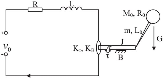
Figure 1.
Structure diagram of electromechanical system.
Considering that the quantization is inevitable in remote control, we think about the quantized input in (57), where is defined in (12). By performing the coordinate transformation , , and , the electromechanical system can be further expressed as
In the control process, each input variable selects six nodes for , , and in their compact sets. The width of the basis functions is selected as 2. Thus, nodes are contained in , with centers distributed evenly in ; nodes are included in , with centers distributed evenly in ; and nodes are included in , with centers distributed evenly in .
In the following, we apply Theorem 1 to make y follow in a given time s. The block diagram of the control system structure is shown in Figure 2.
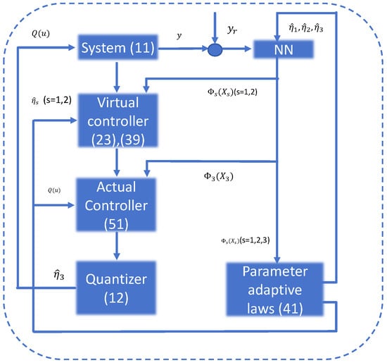
Figure 2.
The block diagram of the proposed scheme.
The simulation is conducted using MATLAB, with a sampling time of 0.01 s. The parameters of the electromechanical system are listed in Table 1. We choose the design parameters as , , , , and , and set the initial conditions as . Comparing this with the adaptive predefined-time control scheme in [45], the actuator quantization is taken into the control design, which is more applicable to the remote control system. To validate the effectiveness of the proposed scheme, a tracking performance comparison between the paper and [45] is given in Figure 3 under the same initial conditions and parameters, where the output hysteresis is neglected and actuator quantization is considered in [45]. From Figure 3, it is evident that the proposed method in our work achieves higher convergence accuracy under actuator quantization. Figure 4, Figure 5 and Figure 6 exhibit the curves of state variables (angular position), (angular velocity), and (angular acceleration), respectively. From Figure 7, the adaptive parameters are bounded. Figure 8 depicts the control signal u and the quantized signal (angular jerk). As observed in Figure 3, Figure 4, Figure 5, Figure 6, Figure 7 and Figure 8, the developed scheme can achieve the control goal. Furthermore, we conducted a statistical analysis of u and , as summarized in Table 2. The results indicate that the mean value of is slightly lower than that of u, and the variance of is nearly identical to that of u. The lower mean value of compared to u reflects a slight reduction in the control signal’s amplitude after quantization.

Table 1.
Parameters of the electromechanical system.
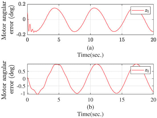
Figure 3.
The trajectory of the tracking error under this paper (a) and [45] (b).
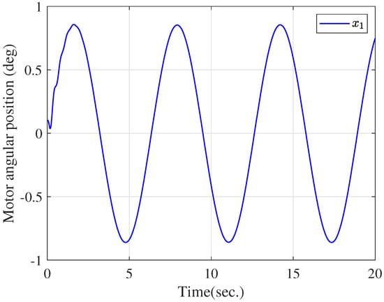
Figure 4.
The trajectory of .
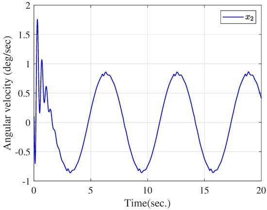
Figure 5.
The trajectory of .
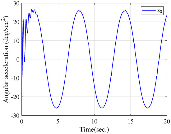
Figure 6.
The trajectory of .
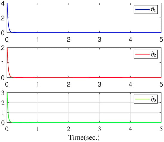
Figure 7.
The trajectories of , , and .
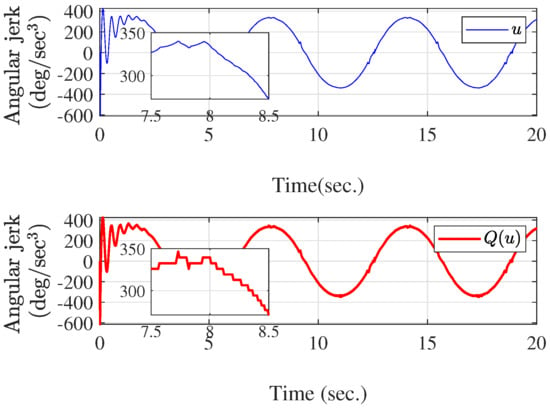
Figure 8.
The trajectories of u and .

Table 2.
Performance evaluation of control input u and quantized input .
5. Conclusions
A predefined-time control strategy is presented for an unknown nonlinear system with actuator quantization. The neural networks are applied to approximate the unknown nonlinearity of the system. To facilitate the stability analysis in the presence of approximation error, the predefined-time stability criterion is first introduced. This criterion gives an effective means of the predefined-time control based on the neural network’s framework. A new quantized control design is then presented. This design not only ensures the predefined-time stability, but the singular problem is overcome in the backstepping control design because of repeatedly differentiating for virtual controllers. Compared with the existing quantized control studies, the settling time is not influenced by the initial state and can be set based upon the system requirement. Finally, the feasibility of the main result is tested using an example.
Author Contributions
Conceptualization, W.Z. and B.Y.; methodology, W.Z.; software, W.Z.; validation, W.Z. and B.Y.; formal analysis, W.Z.; investigation, W.Z.; resources, B.Y.; writing—original draft preparation, W.Z.; writing—review and editing, W.Z.; visualization, W.Z.; supervision, B.Y.; project administration, B.Y.; funding acquisition, W.Z. All authors have read and agreed to the published version of the manuscript.
Funding
This research received no external funding.
Data Availability Statement
No new data were created or analyzed in this study. Data sharing is not applicable to this article.
Conflicts of Interest
The authors declare no conflicts of interest.
References
- Elia, N.; Mitter, S. Stabilization of linear systems with limited information. IEEE Trans. Autom. Control 2001, 9, 1384–1400. [Google Scholar] [CrossRef]
- Hayakawaa, T.; Ishii, H.; Tsumurac, K. Adaptive quantized control for linear uncertain discrete-time systems. Automatica 2009, 3, 692–700. [Google Scholar] [CrossRef]
- Liberzon, D.; Hespanha, J. Stabilization of nonlinear systems with limited information feedback. IEEE Trans. Autom. Control 2005, 6, 910–915. [Google Scholar] [CrossRef]
- Gao, H.; Chen, T. A new approach to quantized feedback control systems. Automatica 2008, 2, 534–542. [Google Scholar] [CrossRef]
- Persis, C.D.; Isidori, A. Stabilizability by state feedback implies stabilizability by encoded state feedback. Syst. Control Lett. 2004, 11, 249–258. [Google Scholar] [CrossRef]
- Gao, H.; Meng, X.; Chen, T. Stabilization of networked control systems with a new delay characterization. IEEE Trans. Autom. Control 2008, 10, 2142–2148. [Google Scholar] [CrossRef]
- Hayakawaa, T.; Ishii, H.; Tsumurac, K. Adaptive quantized control for nonlinear uncertain systems. Syst. Control Lett. 2009, 9, 625–632. [Google Scholar] [CrossRef]
- Zhou, J.; Wen, C.; Yang, G. Adaptive backstepping stabilization of nonlinear uncertain systems with quantized input signal. IEEE Trans. Autom. Control 2014, 2, 460–464. [Google Scholar] [CrossRef]
- Liu, Z.; Wang, F.; Zhang, Y.; Chen, C.L.P. Fuzzy adaptive quantized control for a class of stochastic nonlinear uncertain systems. IEEE Trans. Cybern. 2016, 2, 524–534. [Google Scholar] [CrossRef]
- Wang, F.; Liu, Z.; Zhang, Y.; Chen, C.L.P. Adaptive quantized controller design via backstepping and stochastic small-gain approach. IEEE Trans. Fuzzy Syst. 2016, 4, 330–343. [Google Scholar] [CrossRef]
- Wang, H.; Liu, P.X.; Xie, X.; Liu, X.; Hayat, T.; Alsaadi, F.E. Adaptive fuzzy asymptotical tracking control of nonlinear systems with unmodeled dynamics and quantized actuator. Inf. Sci. 2021, 10, 779–792. [Google Scholar] [CrossRef]
- Wang, F.; Liu, Z.; Zhang, Y.; Chen, C.L.P. Adaptive quantized fuzzy control of stochastic nonlinear systems with actuator dead-zone. Inf. Sci. 2016, 11, 779–792. [Google Scholar] [CrossRef]
- Tang, Y. Terminal sliding mode control for rigid robots. Automatica 1998, 1, 51–56. [Google Scholar] [CrossRef]
- Bhat, S.P.; Bernstein, D.S. Continuous finite-time stabilization of the translational and rotational double integrators. IEEE Trans. Autom. Control 1998, 5, 678–682. [Google Scholar] [CrossRef]
- Bhat, S.P.; Bernstein, D.S. Finite-time stability of continuous autonomous systems. SIAM J. Control Optim. 2000, 6, 751–766. [Google Scholar] [CrossRef]
- Li, H.; Zhao, S.; He, W.; Lu, R. Adaptive finite-time tracking control of full state constrained nonlinear systems with dead-zone. Automatica 2019, 2, 99–107. [Google Scholar] [CrossRef]
- Zhang, Y.; Wang, F.; Yan, F. Fast finite time adaptive neural network control for a class of uncertain nonlinear systems subject to unmodeled dynamics. Inf. Sci. 2021, 7, 306–325. [Google Scholar] [CrossRef]
- Wang, F.; Chen, B.; Sun, Y.; Gao, Y.; Lin, C. Finite-time fuzzy control of stochastic nonlinear systems. IEEE Trans. Cybern. 2020, 6, 2617–2626. [Google Scholar] [CrossRef]
- Lu, K.X.; Liu, Z.; Lai, G.Y.; Chen, C.L.P.; Zhang, Y. Adaptive fuzzy output feedback control for nonlinear systems based on event-triggered mechanism. Inf. Sci. 2019, 6, 419–433. [Google Scholar] [CrossRef]
- Sui, S.; Chen, C.L.P.; Tong, S.C. Event-trigger-based finite-time fuzzy adaptive control for stochastic nonlinear system with unmodeled dynamics. IEEE Trans. Fuzzy Syst. 2021, 7, 1914–1926. [Google Scholar] [CrossRef]
- Huang, J.; Wen, C.; Wang, W.; Song, Y.D. Design of adaptive finite-time controllers for nonlinear uncertain systems based on given transient specifications. Automatica 2016, 7, 395–404. [Google Scholar] [CrossRef]
- Wang, F.; Zhang, Y.; Zhang, L.; Zhang, J.; Huang, Y. Finite-Time Consensus of Stochastic Nonlinear Multi-agent Systems. Int. J. Fuzzy Syst. 2020, 2, 77–88. [Google Scholar] [CrossRef]
- Sui, S.; Chen, C.L.P.; Tong, S.C. Neural network filtering control design for non-triangular structure switched nonlinear systems in finite-time. IEEE Trans. Neural Netw. 2019, 7, 2153–2162. [Google Scholar]
- Wu, J.; Chen, W.S.; Li, J. Global finite-time adaptive stabilization for nonlinear systems with multiple unknown control directions. Automatica 2016, 7, 298–307. [Google Scholar] [CrossRef]
- Zhu, Z.; Xia, Y.Q.; Fu, M.Y. Attitude stabilization of rigid spacecraft with finite-time convergence. Int. J. Robust Nonlinear Control 2011, 4, 686–702. [Google Scholar] [CrossRef]
- Polyakov, A. Nonlinear feedback design for fixed-time stabilization of linear control systems. IEEE Trans. Automat. Control 2012, 8, 2106–2110. [Google Scholar] [CrossRef]
- Zuo, Z.Y. Non-singular fixed-time terminal sliding mode control of nonlinear systems. IET Control Theory Appl. 2015, 2, 545–552. [Google Scholar]
- Li, J.P.; Yang, Y.N.; Hua, C.C. Fixed-time backstepping control design for high-order strictfeedback non-linear systems via terminal sliding mode. IET Control Theory Appl. 2017, 5, 1184–1193. [Google Scholar] [CrossRef]
- Hua, C.C.; Li, Y.F.; Guan, X.P. Finite/Fixed-Time Stabilization for Nonlinear Interconnected Systems with Dead-Zone Input. IEEE Trans. Autom. Control 2017, 5, 2554–2560. [Google Scholar] [CrossRef]
- Sun, Y.M.; Wang, F.; Liu, Z.; Zhang, Y.; Chen, C.L.P. Fixed-time fuzzy control for a class of nonlinear systems. IEEE Trans. Cybern. 2022, 5, 3880–3887. [Google Scholar] [CrossRef]
- Sun, J.L.; Yi, J.Q.; Pu, Z.Q. Fixed-time adaptive fuzzy control for uncertain nonstrict-feedback systems with time-varying constraints and input saturations. IEEE Trans. Fuzzy Syst. 2022, 4, 1114–1128. [Google Scholar] [CrossRef]
- Sánchez-Torres, J.D.; Sanchez, E.N.; Loukianov, A.G. Predefined time stability of dynamical systems with sliding modes. In Proceedings of the 2015 American Control Conference (ACC), Chicago, IL, USA, 1–3 July 2015; Volume 7, pp. 5842–5846. [Google Scholar]
- Sánchez-Torres, J.D.; Gómez-Gutiérrez, D.; López, E.; Loukianov, A.G. A class of predefined-time stable dynamical systems. IMA J. Math. Control Inf. 2018, 3, 1–29. [Google Scholar] [CrossRef]
- Ni, J.; Liu, L.; Tang, Y.; Liu, C. Predefined-time consensus tracking of second-order multiagent systems. IEEE Trans. Syst. Man, Cybern. Syst. 2021, 4, 2550–2560. [Google Scholar] [CrossRef]
- Ferrara, A.; Incremona, G.P. Predefined-time output stabilization with second order sliding mode generation. IEEE Trans. Autom. Control. 2021, 3, 1445–1451. [Google Scholar] [CrossRef]
- Li, K.; Hua, C.C.; Ahn, X.Y.C.K. Output feedback predefined-time bipartite consensus control for high-order nonlinear multiagent systems. IEEE Trans. Circuits Syst. I 2021, 7, 3069–3078. [Google Scholar] [CrossRef]
- Ni, J.K.; Shi, P. Global Predefined Time and Accuracy Adaptive Neural Network Control for Uncertain Strict-Feedback Systems with Output Constraint and Dead Zone. IEEE Trans. Syst. Man Cybern. Syst. 2021, 12, 7903–7918. [Google Scholar] [CrossRef]
- Muñoz-Vázquez, A.J.; Fernández-Anaya, G.; Sánchez-Torres, J.D.; Meléndez-Vázquez, F. Predefined-time control of distributed-order systems. Nonlin. Dyn. 2021, 2, 2689–2700. [Google Scholar]
- Liu, D.C.; Liu, Z.; Chen, C.L.P.; Zhang, Y. Distributed adaptive fuzzy control approach for prescribed-time containment of uncertain nonlinear multi-agent systems with unknown hysteresis. Nonlin. Dyn. 2021, 6, 257–285. [Google Scholar] [CrossRef]
- Zhang, J.X.; Yang, G.H. Low-complexity tracking control of strictfeedback systems with unknown control directions. IEEE Trans. Autom. Control 2019, 4, 5175–5182. [Google Scholar] [CrossRef]
- Mazhar, N.; Malik, F.M.; Raza, A.; Khan, R. Predefined-time control of nonlinear systems: A sigmoid function based sliding manifold design approach. Alexandria Eng. J. 2022, 9, 6831–6841. [Google Scholar] [CrossRef]
- Liu, B.J.; Hou, M.S.; Wu, C.H.; Wang, W.C.; Wu, Z.H.; Huang, B. Predefined-time backstepping control for a nonlinear strict-feedback system. Int. J. Robust Nonlinear Control 2021, 5, 3354–3372. [Google Scholar] [CrossRef]
- Liu, L.; Wang, D.; Peng, Z.; Li, T.; Chen, C.L.P. Cooperative path following ring-networked under-actuated autonomous surface vehicles: Algorithms and experimental results. IEEE Trans. Cybern. 2020, 4, 1519–1529. [Google Scholar] [CrossRef] [PubMed]
- Li, W.Q.; Krstic, M. Prescribed-time output-feedback control of stochastic nonlinear systems. IEEE Trans. Autom. Control 2023, 3, 1431–1446. [Google Scholar] [CrossRef]
- Zhang, Y.; Chadli, M.; Xiang, Z. Predefined-Time Adaptive Fuzzy Control for a Class of Nonlinear Systems with Output Hysteresis. IEEE Trans. Fuzzy Syst. 2023, 8, 2522–2531. [Google Scholar] [CrossRef]
- Wang, F.; Lai, G.Y. Fixed-time control design for nonlinear uncertain systems via adaptive method. Syst. Control Lett. 2020, 6, 104704. [Google Scholar] [CrossRef]
- Hardy, G.H.; Littlewood, J.E.; Polya, G. Inequalities; Cambridge University Press: Cambridge, UK, 1952. [Google Scholar]
- Qian, C.; Lin, W. Non-Lipschitz continuous stabilizers for nonlinear systems with uncontrollable unstable linearization. Syst. Control Lett. 2001, 3, 185–200. [Google Scholar] [CrossRef]
- Polycarpou, M.M.; Ioannou, A.P. A robust adaptive nonlinear control design. Automatica 1993, 6, 1365–1369. [Google Scholar]
- Dawson, D.M.; Carroll, J.J.; Schneider, M. Integrator backstepping control of a rush DC motor turning a robotic load. IEEE Trans. Control Syst. Technol. 1994, 9, 233–244. [Google Scholar] [CrossRef]
Disclaimer/Publisher’s Note: The statements, opinions and data contained in all publications are solely those of the individual author(s) and contributor(s) and not of MDPI and/or the editor(s). MDPI and/or the editor(s) disclaim responsibility for any injury to people or property resulting from any ideas, methods, instructions or products referred to in the content. |
© 2024 by the authors. Licensee MDPI, Basel, Switzerland. This article is an open access article distributed under the terms and conditions of the Creative Commons Attribution (CC BY) license (https://creativecommons.org/licenses/by/4.0/).