Abstract
Origami exhibits the remarkable ability to transform into diverse shapes, including quadrilaterals, triangles, and more complex polygons. This unique property has inspired the integration of origami principles into engineering design, particularly in the development of foldable mechanisms. In the field of robotics, when combined with actuators, these foldable mechanisms are referred to as active origami. Origami-based mechanisms play a pivotal role as versatile end effectors or grippers, enabling them to accurately trace desired trajectories. The performance of these mechanisms heavily relies on their specific fold patterns. To shed light on their capabilities, this study focuses on five representative structures using spherical mechanisms: oriceps, Miura ori, MACIOR, and two hexagonal structures. To assess their potential, a comparative analysis is conducted, evaluating their kinematic and scaling performances. The analysis employs the “scaling factor” as a metric, which quantifies the mechanical advantage of these mechanisms. This metric aids in the selection of appropriate structures for various applications.
Keywords:
scaling factor; active origami; kinematics; fold patterns; robotic grippers; end effectors 1. Introduction
Origami has long been revered for its artistic beauty and intricate patterns, captivating artisans and artists. In recent times, origami has transcended its traditional realm and found a myriad of applications in engineering and science. The diverse utility of origami includes engineering aspects [1]. Traditional rigid grippers need actuators like motors to actuate the gripper in a single direction. They are also bulky and occupy a lot of space. On the contrary, origami-based mechanisms are easily actuated using actuators such as magnets, and they occupy lesser space than the rigid counterparts. Moreover, they are easily manufactured due to their relatively planar geometry. Previous research has found applications of origami folding, the kinematics, and the topology of folding [2]. Their kinematic architectures have been studied in [3]. The inherent compliance of origami structures enables them to achieve trajectories that are impossible with standard mechanisms. Researchers have developed mechanisms on the surfaces of objects such as cones [4,5]. The required action or output is accomplished with minimal inputs, giving a reduced degree of freedom than conventional mechanisms, reducing the dependent parameters and increasing controllability. Along with the advantages, origami robots often present challenges due to their inherent nonlinear models.
Kinematic models generally assume the structures to have zero thickness or width at the folds and creases. Considering these parameters causes the computation to become difficult due to nonlinearities and local bending present in the governing equations. Researchers have also found models to account for the inherent thickness present in origami folds [6,7]. Overcoming the intrinsic nonlinear modeling of origami robots further leads to meta-material research, which are structures created by humans with no precedent mechanical properties. Previous researchers have tried the folding possibilities using reinforced concrete [8] and graphene oxide for origami fabrication [9].
Origami-based mechanisms have a wide range of applications [10,11]. Miura ori and its similar structures are used as unmanned aerial vehicles (UAVs) and finger exoskeletons [12]. Origami structures are also used to develop flexible solar panels. The spherical mechanisms from origami modeling have been used to open car doors [13]. Origami structures have been developed that can mimic the motion of umbrellas [14]. Origami structures with single and multiple degrees of freedom can be used as deployable arms [15,16,17]. The structures are used as tiny hands capable of twisting and gripping various objects [18]. With soft robotic structures [19,20], origami actuation can behave like elevator platforms [21]. Variations of origami structures are used as jumping robots by controlling and regulating their inherent compliance [22]. Origami mechanisms using peristaltic gait [23] produce flipping and snapping motions. Origami also plays a significant role in the field of biomedical engineering, such as surgical retractors for tissue interaction [24] and the magnetic resonance imaging of joints [25]. Its application as a grasper can aid in surgeries [26]. A MACIOR can mimic a caterpillar-based gait [27]. Origami structures have been used for wireless communication between different robots [28]. Buildings have origami-based modeling to share an architectural aspect [3].
Different applications of origami use different types of structures with different numbers of motion generation mechanisms. It is also possible to manipulate the stiffness of an origami structure with the help of curved creases to obtain a range of mechanical advantages for the same structure [29].
Sensors in origami have been possible using embedded systems. Some examples of possible origami sensors include micro-fluid channels filled with metallic constituents that can measure bending strain, carbon ink curvature sensors, and piezoelectric sensors in an origami structure. The control of an origami robot is usually simple at a low level, with angles between folds being one of the main parameters. At higher levels, it becomes complicated due to the unconstrained nature of origami, leading to multiple degrees of freedom. The low-level controls are accountable for nonlinearities in the origami motion. It also depends on the type of folding, i.e., whether they are external or internal self-folding systems.
Algorithms have been developed for the low-level control of desired origami shapes. Systems, such as an origami worm, have gait generators to achieve the gait patterns.
Past research has focused on the general modeling of origami and different parameters in an origami-based robot [12]. The ability of origami to fold in any manner to produce any geometric folding leads to the necessity of an algorithm for folding, not only theoretically but also in the form of software that can visually provide us an insight into folding.
While the literature presents the kinematics by the origami structures [30] and properties of origami motion generation structures, this work presents an insight into the comparison of five different base structures based on the scaling factor. The scaling factor refers to the ratio by which the input motion is scaled in the output, and it does not have anything to do with the size of the origami structure. The scaling factor helps choose between origami structures for different requirements of manipulation. It presents an insight into the suitable structure for a required application based on its scaling effects. This work also provides insight into the ability of the material to reduce the scaling factor of an origami mechanism due to the deformation energy lost in the creases. Through this work, we also study the characteristics of three new origami structures, called MACIOR, and two hexagonal structures. The kinematics presented by the literature is extended and studied for these new structures introduced. Additionally, we also generate novel variations of the MACIOR structure so that these grippers not only pinch (normal gripping) but can also twist, which provides gripping forces in two orthogonal directions. These variations indicate that a single input force can provide gripping in two directions, which could be used in twisting requirements such as opening a bottle lid. We finally compare these structures based on their scaling factor. This is useful for providing information about what type of structure to select or what family of structures, based on the scaling factor of the rigid structure, which can help us to select based on the application for which the origami is being used. Furthermore, if the force requirements are available for gripping, this study helps us understand the input force to be provided and which structure needs the least or highest input force based on the angle at which the object is being gripped by the structure. The theory section introduces spherical mechanisms, scaling factors, and their modeling of origami mechanisms. Further sections provide insight into the performances of individual origami motion generation structures, which is followed by a comparison of these origami mechanisms, suitable materials for fabrication, and specific applications for structures.
2. Scaling Factor of Origami Structures
The scaling factor introduced in this paper is defined in the Introduction section as the ratio by which the input motion is transferred to the output. It is commonly known as a mechanical advantage and is a dimensionless quantity. The scaling factor of a compliant mechanism can be calculated by assuming it to be a rigid mechanism and compensating for the loss in elastic potential energy, as obtained from [31]. A scaling factor of higher than one implies that the mechanical advantage is over one and is used for amplification purposes.
A scaling factor of less than one implies that the mechanical advantage is less than one, necessary for purposes requiring fine manipulation. This concept can be applied to origami-based foldable mechanisms as well.
where is the scaling factor of the compliant mechanism; is the scaling factor, assuming it to be a rigid mechanism (referred to as just here onwards); is the small change in strain energy; and is the small change in work.
In origami-based designs, the folds function as joints, categorized into two types: creased folds and smooth folds [32]. Creased folds act as hinges, represented by straight lines without occupying any area. Smooth folds involve bending a portion of the paper, as shown in Figure 1, with the middle part of the origami structure serving as the bending joint. There are two types of folding directions: mountain folds and valley folds [32]. Mountain folds enter the plane of the paper. Valley folds come out of the plane of the paper.
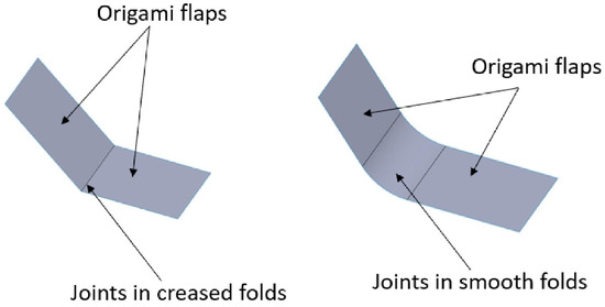
Figure 1.
An illustration of the smooth fold and creased fold acting as joints in a two-flap origami, where the flaps act as linkages.
Origami with creased folds can be modeled and visualized with the help of spherical mechanisms [33].
Spherical mechanisms are spatial mechanisms where the pin joints are not parallel, as shown in Figure 2. The axis of every revolute joint in a spherical mechanism intersects at a common point, which becomes the origami’s vertices about which the spherical mechanisms are built.

Figure 2.
A spherical degree of four vertices, used to model the four sides of an origami structure. The intersection of axes forms a remote center of motion and acts as the meeting point of the creases of origami.
Hence, the common center acts as the center of the vertex. The joint axes of the spherical mechanism are the crease lines of the origami structures. This point of intersection of different axes acts as a remote center of motion, a property of spherical mechanisms widely used in surgical applications [34]. This mechanism is used for modeling and comparing the performance of origami patterns. Different origami structures have different scaling factors, which differ depending on several physical features of the origami.
Different combinations of spherical mechanisms produce different folding patterns and kinematic results. Origami spherical mechanisms fall into different groups [35,36], possessing a closed chain or an open chain. The spherical mechanism model of these origami patterns helps us understand the kinematics and executed trajectories. The modeling of spherical four-bar and six-bar mechanisms and kinematics based on rotational transformations has been performed in previous research [37,38,39,40,41].
The primary classification of origami folding patterns is based on a closed chain of spherical mechanisms [35] into networks and open chains. The classification branches out depending on the number of spherical mechanisms, chain structure, and periodicity of multiple loops [35].
In the following section, the performances of five different types of origami, namely the oriceps [7,42], Miura ori [43,44], MACIOR [27], and two hexagonal structures, are studied.
3. Oriceps
The oriceps are origami-based forceps that can grip objects. The center rectangle acts as the grounded surface, and the adjacent rectangular flaps act as the end effectors. The trapezoidal flaps act as the active joints and are actuated. The design of oriceps is shown in Figure 3. This causes the downward movement of the rectangular flaps on the right and left sides, which causes a gripping motion and grips anything between the two sides. Oriceps comprise four spherical mechanisms: two such mechanisms in series, and two parallel. This model of oriceps has been inspired by Shafer’s chamfer [7], a structure composed of two spherical mechanisms. The oriceps do not have a loop of shared folds with the spherical mechanisms and follow a simple chain of two spherical mechanisms parallel to another set of similar mechanisms. It can be called an extended version of a coupled origami type [7]. The two parallel spherical mechanisms can be fused into a single mechanism, as shown in Figure 3. The two linkage assemblies form a combination of two spherical mechanisms fused about the axis due to the symmetry of the oriceps. The four vertices of the ground rectangle serve as the four centers of the respective spherical mechanisms. The four sets of spherical mechanisms intersect at their respective vertices at the ground link of the Oriceps, as seen in Figure 3. The motion of the origami structure can be seen in Figure 4.
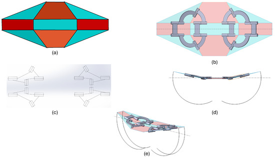
Figure 3.
(a) Top view of oriceps as a flat surface. The trapezium-shaped flaps are actuated, providing output at the rectangular flaps. (b) The mechanism architecture of the oriceps and the spherical modeling of the origami structure is shown. The symmetry of the structure reduces the number of spherical structures from four to two. (c) The kinematic architecture of the revolute joint network is shown on the right. (d,e) The workspace of the output link of the oriceps, from an isometric and orthographic perspective, is also shown. The path traced is a circle, and it represents the pinching motion of the end effectors.

Figure 4.
The motion of the oriceps from two orthogonal views, the front view and side view. The angle is taken as sixty degrees, and the four views show the progressive motion of pinching or gripping the structure.
3.1. Kinematics
The kinematics of the origami is computed as follows. This is based on the research shown in [45,46]. The output and input angle of oriceps can be related using the following equations. The sides of a single spherical four-bar mechanism are taken as shown in Figure 5.
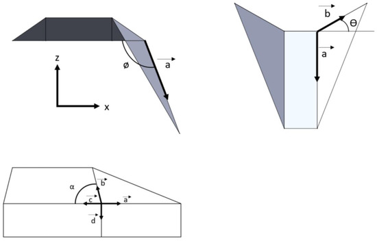
Figure 5.
The orthogonal views of the oriceps with vectorial representations and angular parameters. The angle produced by the output link with the ground link is measured as , and the input angle of actuation is . The four vectors of a four-degree vertex are highlighted for kinematic analysis.
Figure 5 shows the orthogonal views of oriceps with vectors. The input angle of actuation is , and the output angle is . Note that is the angle of the trapezium slant edge with the base.
The sides of a single spherical joint are represented as vectors , , , . Each of them is taken as a unit vector. The origin is taken as the vertex where all the vectors meet. The vectors can be represented in terms of their magnitude and argument as
The coordinates of after a rotation of in the positive direction is given by . Let the vector a be represented as . The y component is 0 as is on the x–z plane. We take the dot product of a and b vectors, whose result is the cosine of the angle between them, which is equal to . Thus, we obtain the following equations:
Because the vector a is a unit vector, we obtain the following equation:
Solving these two equations, we arrive at the following:
The angle of the output flap is given by:
Hence, the relation between the input and output flap angle, , can be plotted in Figure 6.
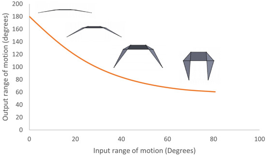
Figure 6.
The plot of the output to input range of motion of the oriceps, measured in degrees. As the oriceps motion folds, the output angles decrease, indicating the pinch motion of the end effectors up to an angle of approximately eighty degrees.
3.2. Scaling Factor
The scaling factor of the oriceps is dependent on several parameters. There are several works on the scaling factor for a multiple-input actuation system [45,46]. Our discussion will stick to a single input at the trapezoidal faces of the oriceps. The scaling factor of oriceps has been derived from previous works [45,46] according to Equation (1) as
where represents the sector angles and represents the dihedral angles. Equation (11) gives us the scaling factor of a rigid oriceps mechanism. Solving by substituting the values, we obtain the following equation.
where and are shown in Figure 5. The variation of the scaling factor with the input angle of actuation for at sixty degrees is shown in Figure 7.
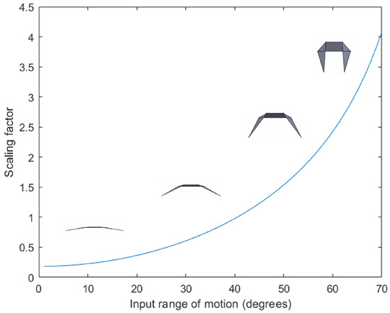
Figure 7.
This is a plot of the scaling factor versus the range of motion of the origami structure. The plot of the scaling factor shows that it can be used for fine manipulation as well as amplification purposes.
4. Miura Ori String
The Miura ori string, an element created out of a Miura origami [44] is another type of origami fold pattern that can perform the gripping motion. It consists of quadrilateral panels that fold in specific directions to produce the gripping action. It can also mimic the motion exhibited by the fingers, such as finger flexion. Miura ori does not have a grounding. The red trapezoidal flaps are the active joints actuated, and the green parallelogram flaps are the end effectors. There are two types of strings, symmetric and asymmetric strings. If the center red trapezium angles in Figure 8 are the same, the string is symmetric. While symmetric strings can only grip, asymmetric strings can also twist and wrap about the vertical axis along the center of mass of the structure for different types of angles, as performed in [47].
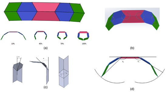
Figure 8.
(a) The design of a Miura ori string, with six trapezoidal and four parallelogram linkages. The red trapezoidal flaps produce a motion in the green parallelogram links connected by the blue trapeziums. Below is the motion of Miura ori, as the trapezium fold is actuated at different stages. (b) The series of spherical mechanisms of Miura ori showcase a network of four spherical mechanisms in series, with the vertices of origami creases acting as remote centers of motion. (c) The angles and are in the z–x plane and x–y plane, respectively. One side of the Miura ori structure is shown. The is the angle measured along the pinch direction, and is the direction that causes twists of an asymmetric Miura ori structure. (d) The workspace of a pinch Miura ori end effector and angles are measured in degrees. The workspace traced is a circular arc, providing a pinching action.
Miura origami can be modeled as a branch of spherical four-bar mechanisms in series, forming a 1-DOF mechanism. The motion of the Miura ori is represented in phases as shown in Figure 8.
4.1. Kinematics
The position of the end effectors of a Miura ori string is determined by the angles of the Miura center link. A comprehensive kinematic analysis has been carried out in the work in [48]. When the link is symmetric, the Miura can exhibit only motion that can pinch. Hence, the input parameter would be , the angle of actuation, and , the angle of the end effector. When the angles are asymmetric, we obtain an additional component, representing the movement along the perpendicular axis to the plane of . The angles are illustrated in Figure 8, along with the spherical mechanism visualization. Previous works [48] have carried out kinematic position analysis and have developed a relation between the input actuation angle . The Miura ori angles are and , and the output angles are and , as shown in Figure 8. The angle is the actuation angle of the trapezoidal input flaps. For a symmetric Miura ori, is zero, and the origami structure does not exhibit twisting or wrapping motion.
The workspace of the end effector of a pinch-type Miura ori is shown in Figure 8. The twisting and wrapping Miura ori additionally have a lateral displacement, measured by the angle .
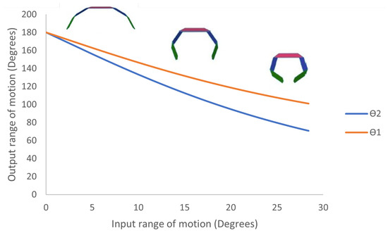
Figure 9.
The variation of the output range of motion and with the input range of motion, all measured in degrees. For an angle of thirty degrees of input, the end effector reaches its final position.
The angles and are given by the following expressions [48]:
where
where and are the angles of the Miura ori center; and are the output angles as seen in Figure 8. The angle is the angle of actuation.
4.2. Scaling Factor
The scaling factor of the Miura ori string can be computed for two directions: along the pinch direction and twist direction. The scaling factor can be written as a function of differentials of the driving and driven angles. The scaling factor of a Miura ori string as a rigid model can be expressed as
Solving the above equation gives:
where
Upon solving this, we obtain:
where
Plotting the above two equations using MATLAB, we obtain the following plot as shown in Figure 10.
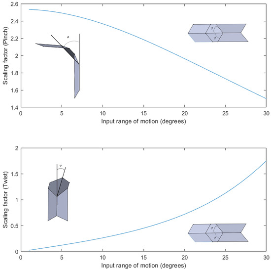
Figure 10.
The variation of scaling factor along the pinch and twist directions with input range of motion. The scaling factor decreases in the pinch motion with actuation but increases in the twist direction.
5. MACIOR Origami with a Six-Degree Vertex
MACIOR stands for magnetically actuated caterpillar-inspired origami robot, originating from previous research where several MACIOR units are combined to form a robotic worm [27]. The MACIOR origami with six vertices is the third type of origami under comparison. One unit of this origami is modeled. The MACIOR origami is extensively folded, comprising triangular folds. A single unit of the six-degree vertex MACIOR includes twelve triangles. The central triangular flaps are actuated, and the triangular flaps form an end effector at either end. Unlike the four-bar spherical mechanisms, a single vertex of the MACIOR unit has six intersecting lines, which gives rise to a spherical six-bar mechanism, as illustrated in Figure 11. A single MACIOR unit can be taken as three rectangular regions with four triangles inscribed. Upon actuating the middle region, a MACIOR exhibits a gripping motion as shown in Figure 11. The MACIOR structure must be taken to a convenient angle manually to avoid coincident flaps leading to a singularity or toggle point in the motion. A MACIOR is actuated in reverse to return to its initial state, implying bidirectional actuation.
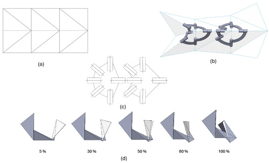
Figure 11.
(a) A single MACIOR unit cell and its joint architecture. A single unit comprises twelve triangular flaps, which constitute the creases of the origami structure. (b,c) The spherical mechanism modeling of a MACIOR origami is shown. It consists of two spherical six-degree vertex folds, with the joint axes intersecting at the center of the creases, acting as a remote center of motion. (d) The gripping pinching motion of the MACIOR structure is shown at various levels. The structure is taken to the initial position manually to avoid any singularity.
5.1. Kinematics
A MACIOR has a six-bar 6R spherical mechanism. The kinematics of a MACIOR has multiple degrees of freedom. One way of solving for a MACIOR is using the loop closure method explained in [38], which gives a relation between the angles rotated by the different spherical joints in the 6R mechanism. We assume that one input angle rotates by twice the actual angle keeping the other link fixed. It does not alter the solution as the relative angular displacements between the links do not change. The angles measured are shown in Figure 12. The angular displacements of symmetric links are equal. The angle is the input angle, and is the output angle. Angles and are the intermediate joint angles. is the angle created by the diagonal crease of a MACIOR with the horizontal crease.
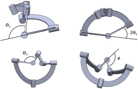
Figure 12.
The measure of different joint angles of the 6R spherical mechanism, where is the input, is the output, and , are intermediate angles.
The loop closure equations have two components: the rotation of each link, which is variable and denoted by Z, and the rotation of the spherical links that are fixed and denoted by S. The rotations Z are about the z-axis of every joint and S about the x-axis, as mentioned in [38]. Thus, the loop equation for the given 6R spherical mechanism is given by
where is the rotation of the joint, where is , is , and is the fixed rotation corresponding to the joint at Z, with being and being . Solving this according to [23], the final relation relating the several parameters of the 6R mechanism is as follows.
The complex relation above gives the relation between different joint angles of the 6R spherical mechanism. Certain assumptions are made to relate the input angles to the output angles. We have assumed angles and to be set and 120 degrees each. The angle is taken as 30 degrees, resulting in the below relation between the input and output angles.
This variation obtained between the output and input angle of actuation is plotted in Figure 13.
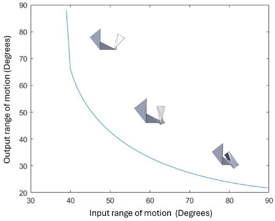
Figure 13.
The plot of the range of motion of the angle produced by the output flap with respect to the input range of motion, in degrees of a MACIOR origami structure. The structure achieves maximum pinch for an angle of ninety degrees actuation.
5.2. Scaling Factor
The MACIOR scaling factor is calculated using a similar method as in the previous cases. The differential of the output and input angles is taken as the scaling factor, calculated in the following equation.
A plot of the scaling factor as a function of the input angle of actuation for a MACIOR is given in Figure 14.
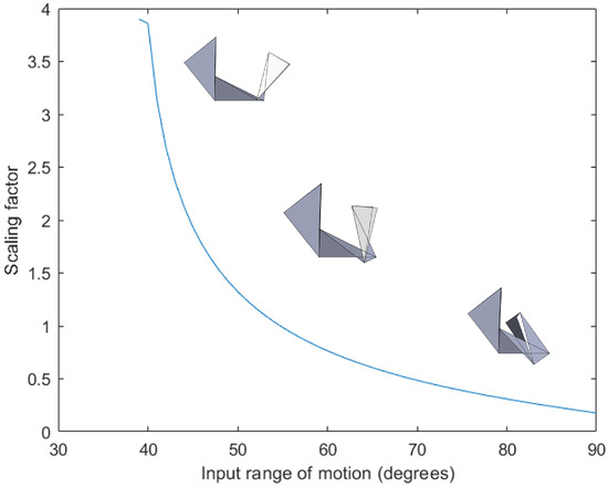
Figure 14.
The scaling factor of a MACIOR origami plotted with respect to the input range of motion, measured in degrees. The scaling factor decreases with an increase in input angle, from the amplification zone to the fine manipulation zone.
MACIORs can also have an asymmetric structure with distinct angles, namely and . The asymmetric structure can lead to twisting motions like Miura ori and other motions depending on the fixed parameters. A flat layout of an asymmetric MACIOR is shown in Figure 15. The side view and top view of the twisting motion of an asymmetric MACIOR are also presented in Figure 15. It indicates that a MACIOR can be used for twisting and wrapping purposes. The six-degree vertex of the MACIOR can generate a myriad of motions that can be chosen by fixing any angles by the user according to convenience and avoiding any toggle points and singularities.
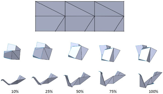
Figure 15.
The layout of an asymmetric MACIOR structure, with triangular flaps at the bottom half and trapezoidal and smaller triangular flaps at the upper half. Below is the motion of an asymmetric MACIOR structure with input actuation angle. The side view in the upper half shows the movement of the structure along the twisting direction, and the front view in the bottom half shows a motion similar to a pinching motion.
6. Hexagonal Structures
Hexagonal structures have a hexagonal base and different patterns of end effectors. Two types of hexagonal motion generation structures are studied to evaluate their performance. The design of the structures is shown below in Figure 16.
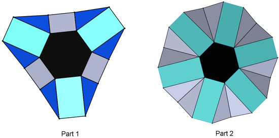
Figure 16.
Two types of hexagonal-based structures. In both cases, the light blue links are the input flaps and the grey flaps are the output flaps.
Pattern 1 has two different-sized rectangular flaps as end effectors, with right triangle flaps joining both. Each hexagon vertex acts as the ground and center of a spherical four-bar mechanism, and the mechanism has six spherical four-bar mechanisms. As the larger flaps are actuated, the minor flaps act as end effectors and grip the object in between them.
Pattern 2 has the same-sized rectangular flaps. Each rectangular flap is joined with the adjacent rectangle flaps by two triangular flaps. Each hexagon vertex is the center of a spherical five-bar mechanism as five edges meet at a vertex. Each flap is independent and requires six actuators to actuate each of the six flaps and has six degrees of freedom. The gripping action of the type 2 structure is illustrated as well. Here, all six flaps come together to grip the target object. The structure can actuate to the point where the triangular flaps become collinear. Once the triangular flaps become collinear, the structure is locked and cannot grip further (Figure 17). The gripping motion of the type 1 and type 2 patterns, in the right of Figure 16, is shown in the Figure 17.
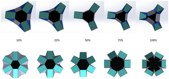
Figure 17.
The top view of the hexagonal structure type 1 in action, where the light blue links are actuated and the grey links come close to each other, providing a three-face gripping action. In the top view of the structure of type 2 in action, the blue links are actuated and the grey links come close, forming a six-face gripping action. In the top view of structure type 2 in action, the blue links are actuated and the grey links come close, forming a six-face gripping action.
We see that the minor rectangular flaps act as end effectors and can grip any object with a thickness more than the triangle encompassed by the three flaps.
To compare the performances of both mechanisms, we carried out an analysis of their output link performances for identical input motions. The angle of the end-effector flap with respect to the hexagonal base was then plotted over time to track their respective performances. As the end-effector link moves according to the input, the angle between the base and the end-effector flap gradually decreases until it reaches a minimum. Structure type 1 covers more angles compared with structure 2 for the same input and at the same time. On the other hand, structure type 2 can grip objects of any size. As the flaps become collinear, the flaps meet the opposite flap and hence grip objects of any size. Moreover, the flaps have six contacts, thereby meaning that the grip is robust.
6.1. Kinematics
The kinematic layout of vectors representing the creases of both the hexagonal structures are shown in Figure 18.
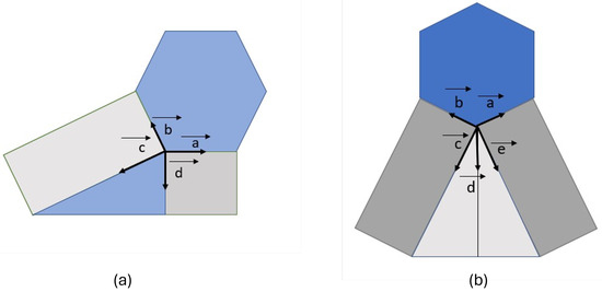
Figure 18.
(a) The vector representation of a single spherical joint in the type 1 Hexagonal structure, where the four-degree folds intersect at the remote center of motion. (b) Type 2 has a vector representation of the spherical five-bar joint, where the five-degree vertex intersects at the remote center of motion, the vertex of the hexagon.
6.1.1. Type 1
The kinematics of the hexagonal origami involves finding the position of the end effector of a particular spherical mechanism out of the six spherical mechanisms. The angle produced by the end-effector flap as a function of the input angle of actuation gives us the position of the end effector for a corresponding actuation angle. Note that is actuated with an angle , and indicates the angle produced by the output vector with the hexagonal surface. The internal angle of the hexagon is . The coordinates of after an actuation angle of are obtained by performing successive rotations and pre-multiplying the transformations. The initial coordinates of C are given by
The final coordinates of C are given by
The angle between and is constant and has a value of . Using geometry, we can find that has a zero x-component throughout the gripping motion. Solving for the two equations below, we obtain the components of .
The final values obtained for are
The output angle is given by
6.1.2. Type 2
Type 2 hexagonal origami comprises six sets of spherical five-bar linkage systems. The angle produced by the output flap with the hexagonal base is calculated similarly to the previous case. In this case, the vector is rotated by an angle of in the clockwise direction. This is a rotation equivalent to aligning with the negative y-axis. Given an input angle of actuation of , the angle between and is constant. Hence, the dot product of the angles would result in the cosine of the angle. The x-component of is zero, which is seen in Figure 18. Solving for the angles, we obtain the following results.
The output angle is calculated as given below:
The plot of the output angle produced with the hexagonal base as a function of the input angle of actuation for both hexagonal structures is shown in Figure 19.
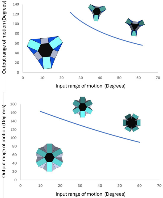
Figure 19.
Plot of the output range of motion angle versus input range of motion angle for the hexagon structures measured in degrees. Type 1 is set at an initial configuration of twenty degrees and actuates to a sixty-degree final angle. A type 2 hexagonal structure is set at an initial angle of ten degrees. The structure is actuated up to sixty degrees.
6.2. Scaling Factor
6.2.1. Type 1
The scaling factor of a type 1 hexagonal structure can be expressed similarly to the previous ones regarding differentials of the driving to driven angles.
Solving for the above equation, we obtain the scaling factor as a function of the actuation angle .
where
where
The variation of the scaling factor with the actuation angle is plotted using MATLAB, as shown in Figure 20.
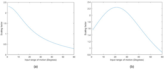
Figure 20.
Plot of a scaling factor with the input range of motion angle measured in degrees. (a) The gripper A has a maximum scaling factor between twenty and thirty degrees, and most of the actuation lies in the amplification zone. (b) The scaling factor of gripper B continuously decreases with the range of motion angle, with parts in both the amplification and fine manipulation zone.
6.2.2. Type 2
For the type 2 hexagonal structure, this can be expressed as the function of the actuation angle as
The above scaling factor formula pertains to a single spherical mechanism. The overall scaling factor of a mechanism also depends on the number of structures. The following plot in Figure 20 gives the variation of the scaling factor with the actuation angle for the type 2 hexagonal structure.
7. Comparison of Different Structures
The structures have been studied individually, and this section brings the study together for comparison. Table 1 and Table 2 give us a comparison of the physical parameters of the origami structures and their arrangement, respectively.

Table 1.
The properties of the five structures in terms of their physical parameters.

Table 2.
Properties of the five structures in terms of their crease arrangement pattern.
The classification of the structures also takes into account the arrangement of spherical mechanisms. A “4 long linear chain” is a crease pattern where there are four centers of spherical mechanisms lying on a linear pattern. Miura ori has four such spherical centers, and a MACIOR has three such centers. Hence, they are classified accordingly in Table 2.
Figure 21 compares the scaling factor of the different origami structures. Different structures have different angles that lead to the final position. Hence, each line ends at different angles of actuation. From Figure 21, we see the variation of the scaling factors of all of the origami structures that have been discussed so far, plotted with respect to the input angle of actuation. Broadly, the workspace can be classified into a binary, namely the amplification zone and the fine manipulation zone. The former consists of regions where the scaling factor is higher than one, while the latter is the opposite, where the scaling factor is less than one. This can prove to be an important factor in making a selection of a particular structure family, given the application and other parameters like the geometry of the object being gripped.
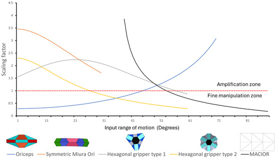
Figure 21.
A comparison of the scaling factor of the various structures with input range of motion angle, measured in degrees. The dotted red lines separate the amplification zone and the fine manipulation zone, giving us the structures that can operate in the corresponding zones for the corresponding angles of actuation.
7.1. Simulation of Oriceps with Different Materials
Material selection for such origami mechanisms has been pondered in previous works. Important criteria for such materials are stiffness and compliance. While the scaling factor and the kinematic relationship between the input and output faces of the origami is independent of the material chosen, the inherent compliance associated with the material and the origami structure causes the scaling factor to reduce slightly below the expected value, depending on the material properties. Hence, the choice of material strongly affects the performance of the origami structures. Commonly used materials include metals, polymers, and plastics. Five different materials, namely titanium metal, ABS plastic, thermosetting polymer PET, thermoplastic polymer PVC, and nylon fiber, were given an input of on both input flaps, and the bending displacement was simulated using SolidWorks 18. URES here stands for the resultant displacement.
From the figure, different models tend to grip in different ways for the same input, as the material’s stiffness plays a vital role in folding an origami. Nylon 101 in Figure 22 showed maximum displacement, and titanium alloy, Figure 22, showed the least displacement of all. This gives us a fair insight into the class of materials to grasp. Therefore, nylon shows the least deviation of the scaling factor from the rigid model scaling factor of the structures.
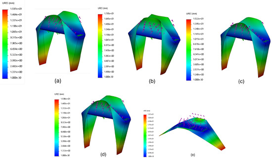
Figure 22.
A simulation of the deflection of folding the oriceps upon application of the same input with five different classes of materials to illustrate the effect of material properties on reducing the compliant scaling factor. (a) is ABS plastic, (b) is Nylon 101, (c) is PET plastic, (d) is PVC rigid, and (e) is titanium alloy.
7.2. Potential Design Concept and Usage in Four-Bar Mechanisms
Several origami designs can extend the use of four-bar mechanisms for actuating the input flaps. These structures fall widely into the class of the oriceps family or the Miura ori family. These can be suitably used depending on the structure in the fine manipulation zone for precision handling and soft gripping or in the amplification zone for magnifying the output. Figure 23 shows patterns similar to the oriceps, which can be used for amplification purposes.
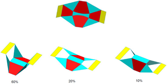
Figure 23.
Pattern that shares similarity with the properties of the oriceps that can be used for applications involving scaling factor amplification, having a scaling factor greater than one. The three views of an origami structure can be used for motion amplification resembling the structure of an oriceps.
Origami models have also been developed by combining two mechanisms and forming extended actuators. Such structures can be used for precision manipulation, where delicate objects are handled. Origami structures also have redundant degrees of freedom for obstacle avoidance and extended actuators, which can be remotely actuated, useful in many applications such as robotic surgery and potential swab collection for medical tests. Some examples are provided in Figure 24 and Figure 25.
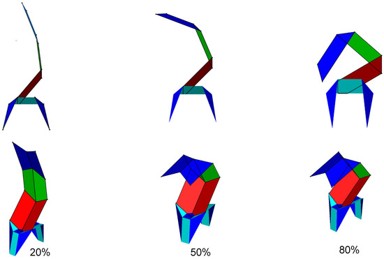
Figure 24.
Extended versions of the oriceps, which could be used for fine manipulation, and remote actuators for holding swabs from medical tests.
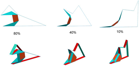
Figure 25.
The isometric and front view of an extended oriceps coupled with a four-bar mechanism. The three views represent three different actuation angles.
The motion of this extended version of an oriceps based on a four-bar mechanism is shown in Figure 25. Unlike the normal oriceps, a different link is grounded to obtain this motion.
7.3. Emerging Trends in Origami
Trends in origami are emerging every day. The above mechanism and structures have widespread potential in the future to serve as grippers, also having the ability to perform two or more degrees of freedom with a single actuator, that is, to act as an under-actuated system. This, when coupled with the scaling effects, can make origami a very viable and efficient alternative to traditional grippers. It is also possible to have one actuator and a modular system so that different origami structures can be attached and released, and this would provide one universal gripper attachment that can be fitted with different structures to produce varying amounts of force or kinematic angles as per the need of the application. With additional twisting capabilities along with simple gripping, under-actuated systems bring in more cost-efficient structures, avoiding additional actuators.
8. Conclusions and Discussions
A comparative analysis was conducted on five distinct origami structures, namely oriceps, Miura ori, MACIOR, and two hexagonal structures, considering their kinematic, dynamic, and geometric characteristics. This study explored how some of these structures can flexibly pinch and twist based on their symmetries. Additionally, a comparative examination of the scaling factor was performed using spherical mechanism modeling. This analysis aids in selecting the most suitable structure shape for different applications, enabling the identification of the most efficient structures based on the comparison of scaling effects. A suitable material for fabricating origami to minimize the loss in scaling factor due to compliance is also discussed. Future research can predict the scaling factor lost due to the inherent compliance in the structures, the ability to use curved creases [29], and designs that mimic complex trajectories.
Author Contributions
Conceptualization, S.K., H.R. and X.X.; methodology, S.K., X.X. and H.R.; software, S.K.; validation, S.K.; formal analysis, S.K. and X.X.; investigation, S.K.; resources, X.X. and H.R.; data curation, S.K.; writing—original draft preparation, S.K.; writing—review and editing, H.R.; visualization, H.R.; supervision, X.X. and H.R.; project administration, H.R. All authors have read and agreed to the published version of the manuscript.
Funding
This work was supported in part by Hong Kong Research Grants Council (RGC) Collaborative Research Fund (CRF C4026-21G), and General Research Fund (GRF 14216022), Regional Joint Fund Project of the Basic and Applied Research Fund of Guangdong Province (GBABF 2021B1515120035).
Data Availability Statement
No new data were created or analyzed in this study. Data sharing is not applicable to this article.
Conflicts of Interest
The authors declare no conflicts of interest.
References
- Turner, N.; Goodwine, B.; Sen, M. A review of origami applications in mechanical engineering. Proc. Inst. Mech. Eng. Part J. Mech. Eng. Sci. 2016, 230, 2345–2362. [Google Scholar] [CrossRef]
- Balkcom, D.; Mason, M. Robotic origami folding. Int. J. Robot. Res. 2008, 27, 613–627. [Google Scholar] [CrossRef]
- Sapienza, V.; Rodonò, G. Kinetic Architecture and Foldable Surface. Athens J. Archit. 2016, 2, 223–236. [Google Scholar] [CrossRef]
- Nelson, T.G.; Zimmerman, T.K.; Magleby, S.P.; Lang, R.J.; Howell, L.L. Developable mechanisms on developable surfaces. Sci. Robot. 2019, 4, eaau5171. [Google Scholar] [CrossRef] [PubMed]
- Yao, W.; Dai, J. Dexterous manipulation of origami cartons with robotic fingers based on the interactive configuration space. J. Mech. Des. 2008, 130, 022303. [Google Scholar] [CrossRef]
- Chen, Y.; Peng, R.; You, Z. Origami of thick panels. Science 2015, 349, 396–400. [Google Scholar] [CrossRef] [PubMed]
- Edmondson, B.J.; Bowen, L.A.; Grames, C.L.; Magleby, S.P.; Howell, L.L.; Bateman, T.C. Oriceps: Origami-Inspired Forceps. In Smart Materials, Adaptive Structures and Intelligent Systems; American Society of Mechanical Engineers: New York, NY, USA, 2013; Volume 1. [Google Scholar] [CrossRef]
- von der Woerd, J.D.; Chudoba, R.; Hegger, J. Single-curved shell structure made out of textile-reinforced concrete plate using a folding technique. Proc. Iass Annu. Symp. 2013, 2013, 1–6. [Google Scholar]
- Yang, H.; Yeow, B.; Chang, T.; Li, K.; Fu, F.; Chen, P. Graphene Oxide-Enabled Synthesis of Metal Oxide Origamis for Soft Robotics. ACS Nano 2019, 13, 5410–5420. [Google Scholar] [CrossRef]
- Lee, M.J.T.; Yeow, B.S.; Cai, C.J.; Tse, Z.T.H.; Ren, H. Prototyping soft origami quad-bellows robots from single-bellows characterization. In Flexible Robotics in Medicine: A Design Journey of Motion Generation Mechanisms and Biorobotic System Development; Academic Press: Cambridge, MA, USA, 2020; pp. 19–37. [Google Scholar]
- Thomson, A.; Hao, C.T.S.; Yanhui, L.O. Modular origami joint operator to create bendable motions with multiple radii. In Flexible Robotics in Medicine: A Design Journey of Motion Generation Mechanisms and Biorobotic System Development; Academic Press: Cambridge, MA, USA, 2020; pp. 101–148. [Google Scholar]
- Rus, D.; Tolley, M. Design, fabrication and control of origami robots. Nat. Rev. Mater. 2018, 3, 101–112. [Google Scholar] [CrossRef]
- Abdul-Sater, K.; Winkler, M.M.; Irlinger, F.; Lueth, T.C. Three-Position Synthesis of Origami-Evolved, Spherically Constrained Spatial Revolute–Revolute Chains. J. Mech. Robot. 2015, 8, 011012. [Google Scholar] [CrossRef]
- Banerjee, H.; Kakde, S.; Ren, H. OrumBot: Origami-Based Deformable Robot Inspired by an Umbrella Structure. In Proceedings of the 2018 IEEE International Conference on Robotics and Biomimetics (ROBIO), Kuala Lumpur, Malaysia, 12–15 December 2018; pp. 910–915. [Google Scholar] [CrossRef]
- Matsuo, H.; Asada, H.H.; Takeda, Y. Design of a Novel Mutliple-DOF Extendable Arm With Rigid Components Inspired by a Deployable Origami Structure. IEEE Robot. Autom. Lett. 2020, 5, 2730–2737. [Google Scholar] [CrossRef]
- Lang, R.J.; Magleby, S.; Howell, L. Single Degree-of-Freedom Rigidly Foldable Cut Origami Flashers. J. Mech. Robot. 2016, 8, 031005. [Google Scholar] [CrossRef]
- Zimmermann, L.; Stankovic, T. Rigid and Flat Foldability of a Degree-Four Vertex in Origami. J. Mech. Robot. 2020, 12, 011004. [Google Scholar] [CrossRef]
- Lee, K.; Wang, Y.; Zheng, C. TWISTER Hand: Underactuated Robotic Gripper Inspired by Origami Twisted Tower. IEEE Trans. Robot. 2020, 36, 488–500. [Google Scholar] [CrossRef]
- Su, Y.; Fang, Z.; Zhu, W.; Sun, X.; Zhu, Y.; Wang, H.; Tang, K.; Huang, H.; Liu, S.; Wang, Z. A High-Payload Proprioceptive Hybrid Robotic Gripper with Soft Origamic Actuators. IEEE Robot. Autom. Lett. 2020, 5, 3003–3010. [Google Scholar] [CrossRef]
- Deshpande, A.R.; Ho, Z.T.; Ren, H. Origami-inspired bi-directional soft pneumatic actuator with integrated variable stiffness mechanism. In Proceedings of the 2017 18th International Conference on Advanced Robotics (ICAR), Hong Kong, China, 10–12 July 2017; pp. 417–421. [Google Scholar] [CrossRef]
- Salerno, M.; Firouzeh, A.; Paik, J. A Low Profile Electromagnetic Actuator Design and Model for an Origami Parallel Platform. J. Mech. Robot. 2017, 9, 041005. [Google Scholar] [CrossRef]
- Tolley, M.T.; Shepherd, R.F.; Karpelson, M.; Bartlett, N.W.; Galloway, K.C.; Wehner, M.; Nunes, R.; Whitesides, G.M.; Wood, R.J. An untethered jumping soft robot. In Proceedings of the 2014 IEEE/RSJ International Conference on Intelligent Robots and Systems, Chicago, IL, USA, 14–18 September 2014; pp. 561–566. [Google Scholar] [CrossRef]
- Banerjee, H.; Pusalkar, N. Single-Motor Controlled Tendon Driven Peristaltic Soft Origami Robot. J. Mech. Robot. 2018, 10, 064501. [Google Scholar] [CrossRef]
- Banerjee, H.; Li, T.; Ponraj, G.; Kumar, K.S.; Lim, C. Origami-Layer-Jamming Deployable Retractor with Variable Stiffness and Tactile Sensing. J. Mech. Robot. 2019, 12, 031010. [Google Scholar] [CrossRef]
- Taylor, A.J.; Slutzky, T.; Feuerman, L.; Ren, H.; Tokuda, J.; Nilsson, K.; Tse, Z.T. MR-Conditional SMA-Based Origami Joint. IEEE/ASME Trans. Mechatron. 2019, 24, 883–888. [Google Scholar] [CrossRef] [PubMed]
- Salerno, M.; Zhang, K.; Menciassi, A.; Dai, J.S. A Novel 4-DOF Origami Grasper with an SMA-Actuation System for Minimally Invasive Surgery. IEEE Trans. Robot. 2016, 32, 484–498. [Google Scholar] [CrossRef]
- Cai, C.J.; Xiao, X.; Kalairaj, M.S.K.; Lee, I.J.; Mugilvannan, A.K.; Yeow, B.S.; Tan, J.H.; Huang, H.; Ren, H. Diversified and Untethered Motion Generation Via Crease Patterning from Magnetically Actuated Caterpillar-Inspired Origami Robot. IEEE/ASME Trans. Mechatron. 2021, 26, 1678–1688. [Google Scholar] [CrossRef]
- Yang, H.; Yeow, B.S.; Li, Z.; Li, K.; Chang, T.; Jing, L.; Li, Y.; Ho, J.S.; Ren, H.; Chen, P.Y. Multifunctional metallic backbones for origami robotics with strain sensing and wireless communication capabilities. Sci. Robot. 2019, 4, eaax7020. [Google Scholar] [CrossRef]
- Zhai, Z.; Wang, Y.; Lin, K.; Wu, L.; Jiang, H. In situ stiffness manipulation using elegant curved origami. Sci. Adv. 2020, 6, eabe2000. [Google Scholar] [CrossRef]
- Qiu, C.; Zhang, K.; Dai, J. Repelling-Screw Based Force Analysis of Origami Mechanisms. J. Mech. Robot. 2016, 8, 031001. [Google Scholar] [CrossRef]
- Salamon, B.A.; Midha, A. An Introduction to Mechanical Advantage in Compliant Mechanisms. J. Mech. Des. 1998, 120, 311–315. [Google Scholar] [CrossRef]
- Hernandez, E.P.; Hartl, D.; Lagoudas, D. Active Origami: Modeling, Design, and Applications; Springer: Berlin/Heidelberg, Germany, 2019. [Google Scholar] [CrossRef]
- Bai, S.; Li, X.; Angeles, J. A review of spherical motion generation using either spherical parallel manipulators or spherical motors. Mech. Mach. Theory 2019, 140, 377–388. [Google Scholar] [CrossRef]
- Yip, H.M.; Li, P.; Navarro-Alarcon, D.; Wang, Z.; Liu, Y. A new circular-guided remote center of motion mechanism for assistive surgical robots. In Proceedings of the 2014 IEEE International Conference on Robotics and Biomimetics (ROBIO 2014), Bali, Indonesia, 5–10 December 2014; pp. 217–222. [Google Scholar] [CrossRef]
- Bowen, L.A.; Grames, C.L.; Magleby, S.P.; Lang, R.J.; Howell, L.L. An Approach for Understanding Action Origami as Kinematic Mechanisms. In Proceedings of the Volume 6B: 37th Mechanisms and Robotics Conference, Portland, OR, USA, 4–7 August 2013. [Google Scholar] [CrossRef]
- Huffman. Curvature and Creases: A Primer on Paper. IEEE Trans. Comput. 1976, 100, 1010–1019. [Google Scholar] [CrossRef]
- Farhang, K.; Zargar, Y.S. Design of Spherical 4R Mechanisms: Function Generation for the Entire Motion Cycle. J. Mech. Des. 1999, 121, 521–528. [Google Scholar] [CrossRef]
- Hernández, S.; Bai, S.; Angeles, J. The Design of a Chain of Spherical Stephenson Mechanisms for a Gearless Robotic Pitch-Roll Wrist. J. Mech. Des. 2006, 128, 422–429. [Google Scholar] [CrossRef]
- Hull, T.C.; Tachi, T. Double-line rigid origami. arXiv 2017, arXiv:1709.03210. [Google Scholar]
- Feng, H.; Peng, R.; Ma, J.; Chen, Y. Rigid Foldability of Generalized Triangle Twist Origami Pattern and Its Derived 6R Linkages. J. Mech. Robot. 2018, 10, 051003. [Google Scholar] [CrossRef]
- Fang, H.; Li, S.; Wang, K. Self-locking degree-4 vertex origami structures. Proc. R. Soc. Math. Phys. Eng. Sci. 2016, 472, 20160682. [Google Scholar] [CrossRef]
- Edmondson, B.J. Development of a Thickness Accommodation Technique for Origami-Inspired Design; Brigham Young University: Provo, UT, USA, 2015. [Google Scholar]
- Kamrava, S.; Mousanezhad, D.; Felton, S.M.; Vaziri, A. Programmable Origami Strings. Adv. Mater. Technol. 2018, 3, 1700276. [Google Scholar] [CrossRef]
- Miura, K. The Science of Miura-Ori: A Review. Origami 2009, 4, 87. [Google Scholar]
- Butler, J.; Bowen, L.; Wilcox, E.; Shrager, A.; Frecker, M.I.; von Lockette, P.; Simpson, T.W.; Lang, R.J.; Howell, L.L.; Magleby, S.P. A Model for Multi-Input Mechanical Advantage in Compliant and Origami-Based Mechanisms. J. Mech. Robot. 2018, 10, 061007. [Google Scholar] [CrossRef]
- Wilcox, E.W.; Shrager, A.; Bowen, L.; Frecker, M.; Lockette, P.V.; Simpson, T.; Magleby, S.; Lang, R.J.; Howell, L.L. Considering mechanical advantage in the design and actuation of an origami-based mechanism. In Proceedings of the ASME Design Engineering Technical Conference, 39th Mechanisms and Robotics Conference, Boston, MA, USA, 2–5 August 2015; ASME: New York, NY, USA, 2016. [Google Scholar] [CrossRef]
- Orlofsky, A.; Liu, C.; Kamrava, S.; Vaziri, A.; Felton, S.M. Mechanically Programmed Miniature Origami Grippers. In Proceedings of the 2020 IEEE International Conference on Robotics and Automation (ICRA), Paris, France, 31 May–31 August 2020; pp. 2872–2878. [Google Scholar] [CrossRef]
- Kamrava, S.; Liu, C.; Orlofsky, A.; Vaziri, A.; Felton, S. A Closed-form Solution for the Kinematics of Asymmetric Miura Vertices. arXiv 2020, arXiv:2001.07657. [Google Scholar]
Disclaimer/Publisher’s Note: The statements, opinions and data contained in all publications are solely those of the individual author(s) and contributor(s) and not of MDPI and/or the editor(s). MDPI and/or the editor(s) disclaim responsibility for any injury to people or property resulting from any ideas, methods, instructions or products referred to in the content. |
© 2024 by the authors. Licensee MDPI, Basel, Switzerland. This article is an open access article distributed under the terms and conditions of the Creative Commons Attribution (CC BY) license (https://creativecommons.org/licenses/by/4.0/).