Article

An Adaptive Magnetorheological Fluid-Based Robotic Claw with an Electro-Permanent Magnet Array

1
Department of Aerospace Engineering, University of Maryland, College Park, MD 20742, USA
2
Altius Space Machines, Broomfield, CO 80020, USA
*
Author to whom correspondence should be addressed.
These authors contributed equally to this work.
Actuators 2023, 12(12), 469; https://doi.org/10.3390/act12120469
Submission received: 17 November 2023 / Revised: 8 December 2023 / Accepted: 12 December 2023 / Published: 16 December 2023
(This article belongs to the Special Issue Advancement in the Design and Control of Robotic Grippers)

Abstract

:
The increasing demand for the adept handling of a diverse range of objects in various grasp scenarios has spurred the development of more efficient and adaptable robotic claws. This study specifically focuses on the creation of an adaptive magnetorheological fluid (MRF)-based robotic claw, driven by electro-permanent magnet (EPM) arrays to enhance gripping capabilities across different task requirements. In pursuit of this goal, a two-finger MRF-based robotic claw was introduced, featuring two magnetorheological (MR) grippers equipped with MR elastomer (MRE) bladders and EPM arrays at the fingertips. The operational principle involved placing a target object between these MR grippers and adjusting the normal force applied to the object for effective grasping. During this process, the contact stiffness of the MR grippers was altered by activating the EPM arrays in three distinct operation modes: passive, short-range (SR), and long-range (LR). Through experimentation on a benchtop material testing machine, the holding performance of the MRF-based robotic claw with the integrated EPM arrays was systematically evaluated. This study empirically validates the feasibility and effectiveness of the MRF-based robotic claw when equipped with EPM arrays.

1. Introduction

Humans can grasp and manipulate objects of a wide range of sizes, weights, and shapes by using fingers dextrously and adaptively. Various industrial automation applications require safely, reliably, and robustly controllable robotic grasping and manipulation technologies that are closer to human hand dexterity [1] and also excel over human capabilities [2] (e.g., the lifting of a heavy-weight object, highly repeatable accurate gripping, and very fast gripping). In the past several decades, various robotic gripping technologies have been developed to produce such grasping dexterity and capabilities. Among these, robotic claws stand out as effective robot grippers due to their straightforward design, offering powerful and precise grips. They excel in performing delicate maneuvers in diverse industrial settings, including assembly, pick-and-place operations, and packaging and palletizing tasks. Also, robotic claws can be used for grasping instruments from spacecraft in space [3] and satellite or space debris removal [4]. Also, they can grasp marine life samples from submarines in the ocean [5]. Generally, robotic claws are designed with a minimum of two fingers that converge from opposing sides to securely grasp an object [6]. Conventional robotic fingers have been mainly made of low elastic compliance materials and are suitable for tightly grasping stiff material objects or power-gripping heavier objects. But, more recently, soft fingers that are made of highly elastic compliance materials have been actively developed to build robotic claws for handling and manipulating fragile or delicate objects and also being suitable to safely operate with humans [7,8]. Lately, there have been advancements in the development of adaptive magnetorheological fluid (MRF)-based robotic claws capable of dynamically altering their contact compliances by adjusting a magnetic field. MRF-based robotic claws offer distinct advantages compared to traditional electric and pneumatic claws. The inclusion of adaptively adjustable elastic compliance components enables MRF-baed robotic claws to grasp objects of diverse shapes and sizes without requiring prior information about the objects. Also, these claws can delicately grip soft and fragile targets without the need for extensive sensors and intricate control algorithms.
In investigations concerning MRF-based robotic claws, Pettersson et al. [9] pioneered the development of a two-finger MRF-based robotic claw designed for the delicate handling of diverse-shaped food products. They utilized partially MRF-filled soft polyurethane bladders affixed to electromagnets (EMs) surfaces. The two-finger MRF-based robotic claw’s holding capabilities were evaluated using a benchtop material testing machine with various wood target objects in different shapes and sizes. Subsequently, the claw was integrated onto a six-axis KUKA robot, successfully executing pick-and-place tests for real foods like tomatoes, carrots, strawberries, broccoli, and grapes without causing damage. Liu et al. [10] introduced a conceptual design for a two-joint robotic finger utilizing MRF, conducting analytical investigations into its grasping torque. Nishida et al. [11] and the same authors in subsequent works [12,13] developed MRF-based universal grippers capable of grasping a broad spectrum of objects without relying on a claw or jaw mechanism. Bernat et al. [14] devised a two-finger magnetorheological elastomer (MRE)-based robotic claw tailored for soft robotic applications. Guan et al. [15] contributed to the field by creating a two-finger soft robotic claw using a 3D-printed hybrid magnetorheological (MR) material, encapsulating an MRF within an MRE matrix. More recently, the same authors [16] assembled a two-finger MRF-based robotic claw employing a conventional EM, evaluating its holding performance through experimental assessments. To gauge the claw’s performance, a set of criteria including dynamic and static holding forces, controllable holding forces, and holding coefficients were proposed and experimentally measured.
In our previous study [
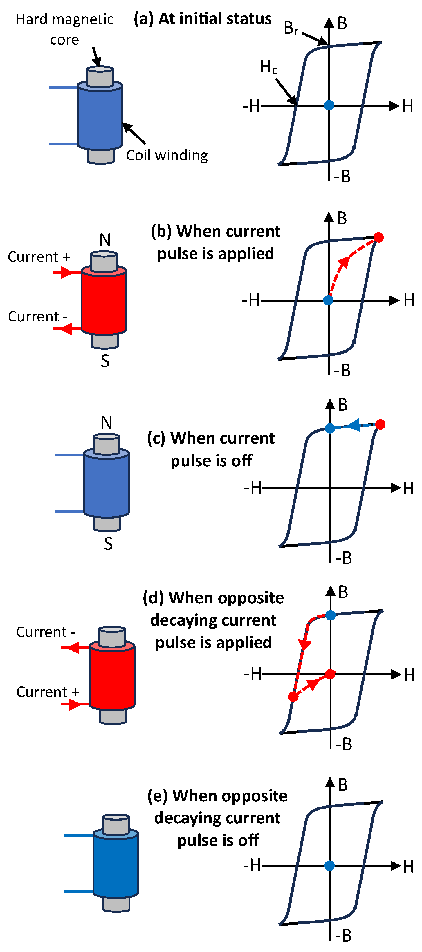
16], round-type conventional EMs were used to activate the stiffening of the MRF, thereby controlling the contact compliance of the MRF-based robotic claw. But, conventional EMs that consist of a coil winding, inner magnetic core, and outer magnetic flux return cannot be continuously operated for a long period of time because of heating up. Because of this fact, the grasping and manipulation operation of the MRF-based robotic claw using the conventional EM should be temporary and also limited to a short period of operating time. To overcome this disadvantage of the MRF-based robotic claw using the conventional EM developed in the previous study, the electro-permanent magnet (EPM) technology is applied to construct the MRF-based robotic claw in this study.
EPMs are known to be solid-state devices whose external magnetic flux can be stably switched on and off by a discrete electrical current pulse, and they retain their magnetic state with zero power. As a result, EPMs can provide a high magnetic field for a longer operating time with low power consumption and no heat-up issue. Thus, the development of an adaptive MRF-based robotic claw energized by the EPMs is addressed in this study. To this end, a two-finger type of MRF-based robotic claw was selected in this study. Two MR grippers that consisted of MRE bladders and EPM arrays were configured at the fingertips of the MRF-based robotic claw. A target object was positioned between these two MR grippers and secured by modifying the normal force applied to the object through the MR grippers. At this time, the contact compliances of the MR grippers were changed by activating the EPM arrays in three different operation modes: passive, short-range, and long-range. Because of those adaptive contact compliance characteristics, the holding forces of the MRF-based robotic claw were also changed by a magnetic field produced by the EPM arrays. By using the testing setup constructed on the Instron material testing machine, the holding performances of the MRF-based robotic claw with the EPM arrays were experimentally evaluated. From this work, the feasibility of the MRF-based robotic claw with the EPM arrays was experimentally confirmed.

2. MRF-Based Robotic Claw with Electro-Permanent Magnet (EPM) Arrays

The MRF-based robotic claw proposed in this study was configured by attaching MR grippers operated via the EPM arrays to the fingertips of the solid fingers. Firstly, the working principle and design of the MR grippers will be explained in detail, and secondly, the testing setup for the holding performance evaluation will be described.

2.1. MR Gripper with the EPM Arrays

Figure 1 presents the schematic for the working principle of the EPM. The EPM consists of the aluminum–nickel–cobalt (AlNiCo) magnetic core inside a coil winding. Generally, magnetic core materials are divided into two main groups via the criterion of coercivity: soft and hard magnetic materials. Soft magnetic materials have a low coercivity and high magnetic permeability, resulting in easy magnetization and demagnetization. Hard magnetic materials have a high coercivity and low magnetic permeability, thereby being hard to be magnetized and also demagnetized. Typically, the intrinsic coercivity values of soft magnetic materials are less than 1 kA/m, while the coercivity of hard magnetic materials is in the range of 1 kA/m–5000 kA/m [17]. AlNiCo magnetic materials exhibit a moderate coercivity range of 1 kA/m–300 kA/m and are suitable for applications that require a balance between magnetization stability and ease of magnetization. Because of this fact, AlNico was selected for the EPM used in this study.
As illustrated in Figure 1, the EPM in this study can be magnetized and demagnetized in five operating steps. At the initial status, the EPM has no magnetic flux density, B, at the zero magnetic field, H (i.e., no current input). In this case, the working point marked as the blue-colored dot (see Figure 1a) in the B-H plot is located at the origin of this plot. Here, the blue-colored dot and blue-colored coil winding mean no current input status. For the magnetization of the EPM, when a current pulse is applied to the coil winding and its magnetic field is sufficiently larger than the coercivity ( H c ) of the magnetic core material, the magnetic flux density of the EPM changes from the zero (i.e., the blue-colored dot) to the peak saturation point (i.e., the red-colored dot in Figure 1b) in the first quadrant of the B-H plot. Here, the red-colored dot and red-colored coil winding mean the current input status. Also, the magnetic pole direction of the EPM can be determined using Ampere’s right-hand grip rule. It should be noted that the magnetization of the EPM in this study was achieved by supplying a short duration of high-frequency current pulse in the kHz range. But, because of the short-duration current pulse, the EPM did not heat up like conventional EMs. On the other hand, when a current pulse is off in Figure 1c, the magnetic flux of the EPM is falling to the point where the magnetic field is zero. This magnetic flux density (i.e., the blue-colored dot in Figure 1c) is called remanence or residual magnetic flux density, B r . At this point, the EPM becomes a permanent magnet and also holds the magnetic pole without requiring any other current input. For the demagnetization, the decaying current pulse waves are applied to the coil winding. Since the opposite magnetic field input is applied, the working point is falling along the magnetic hysteresis loops in the second and third quadrants of the B-H plot (see Figure 1d), but cannot reach the negative peak saturation point in the third quadrant because of the current input amplitude decaying to zero. Finally, the working point (see Figure 1e) reaches the origin of the B-H plot. When the opposite decaying current pulse is off, the EPM is fully demagnetized and has no magnetic pole.
The EPM can be also magnetized to have the opposite of the magnetic pole of Figure 1b if the current pulse direction is reversely applied to the coil winding. Thus, the EPM can be magnetized to have any magnetic pole and also demagnetized by the current pulse. Also, for the magnetization and demagnetization processes of the EPM, it does not need to maintain a continuous current input and is only required to change its working state in the B-H curve.
The EPM explained above has a small magnetic effect area because of a small magnetic core diameter. To increase the magnetic effect area, an EPM array that contains multiple EPMs was used in this study. By using the EPM array, the MR gripper was configured as shown in Figure 2. As seen in this figure, the MR gripper consists of the MRF-filled soft MRE bladder, the EPM array, and the 3D-printed clamping flange with an adjustable hose clamp. Here, the EPM array consists of 16 EPMs (=4 × 4 EPMs), and each EPM has a coil winding that is individually energized by the inhouse current amplifier (maximum voltage: 26 V and maximum instantaneous current: 3 A). Thus, each EPM can produce a magnetic pole on each magnet’s face. The EPM array can produce three different operating modes including passive mode, short-range (SR) mode, and long-range (LR) mode by changing its magnetic pole configuration. The passive mode means that each EPM has no magnetic pole; therefore, no magnetic flux output. In this passive mode, the MRF of the MR gripper is not activated and works as a general fluid. The SR mode was configured to produce higher magnetic flux density close to the magnet’s face, whereas the LR mode was configured such that the magnetic flux of the EPM array is maximized at a longer distance from the EPM’s face. This can be experimentally confirmed from Figure 3. As observed in this figure, the magnetic flux density close to the EPM’s face was nominally 133 mT in the SR mode and 119 mT in the LR mode. But at 9.9 mm away from the EPM’s face, the nominal magnetic flux density was 2.6 mT in the SR mode and 30.3 mT in the LR mode, demonstrating that a magnetic flux density can be achieved in the LR mode. In this case, a Gauss/Teslameter (F.W. Bell, 5080) was used for the magnetic flux density measurement. It should be noted that the magnetic pole patterns in the first and second rows of the EPM array were identical to those in the third and fourth rows. Thus, only the magnetic pole patterns from the first and second rows were measured and presented in Figure 3. On the other hand, there was the fluctuation in the magnetic density magnitude in Figure 3 because the magnetic properties of the AlNiCo magnetic cores and the coil windings in the EPM array were not identical in practice.
On the other hand, as seen in Figure 2, a square shape of the MRE bladder was used to contain the MRF. This MRE bladder was made by dispersing 25% in volume (hereinafter vol%) of magnetizable iron oxide particles into the liquid silicone rubber (Shore 00-20) and cured in a 3D-printed plastic mold. The cross-sectional area of the bladder was 47.0 mm × 47.0 mm, and its thickness was 3.0 mm. The cross-sectional area of the EPM array was 40.9 mm × 40.9 mm, and its height was 43.2 mm. The MRF was synthesized by dispersing 45 vol% bidispersed carbonyl iron particles (i.e., 1:1 mixing ratio of 1–3 microns and 6–10 microns) into a 5000 cSt high-viscosity linear polysiloxane (HVLP) carrier fluid. This MRF was partially filled into the bladder volume enclosed by both the MRE bladder and the EPM array so that the bladder could be easily deformed by the object. Nominally, 75% of the bladder volume was filled with MRF.
The MRE bladder is the compliant component of this MR gripper and is elastically deformed by objects when gripped. The contact compliance of the MR gripper can be adaptively changed by mainly using the MRF energized by the EPM array. In the absence of a magnetic field, the iron particles inside the MRF are randomly distributed and the MRF has no yield stress, which is the stress for the fluid to start and maintain flowing. Thus, the MR gripper is soft in the absence of a magnetic field, and its bladder is passively deformed to the target object’s shape under gripping action. But, if the magnetic field of the EPM array activates the MRF, the iron particles inside the MRF can form particle chains and resist the fluid flow. This fluid resistance of the MRF can be continuously controlled via the magnetic field intensity. Thus, the MRF-filled bladder can be hardened by the EPM array, and its hardness also can be controlled. If the MRF-filled bladder is pressed around an object, some portions of this object will be entrapped inside the bulged bladder. At this time, if the MRF-filled bladder is hardened by the EPM array, the object locks in the bladder. This can be a constraint for the object to release from the MR gripper and also can increase the holding performance of the MRF-based robotic claw. It should be noted that the EPM activates both the MRF and the MRE at the same time. Thus, the MRE bladder itself can be hardened and help to increase the lock-up effect of the MRF. But, the MRF is the main component to harden the bladder of the MR gripper using the EPM array.
In order to observe the contact compliance change of the MR gripper with the EPM array, its contact force was measured in this study. Figure 4 presents the experimental testing setup for the measurement of the contact force of the MR gripper with the EPM array. A benchtop Instron material testing machine (Instron Dynamight 8841) was used, and the object was attached to the load cell fixed to the testing machine. The MR gripper was attached to the hydraulic actuator of the testing machine, and its displacement was measured via a linear variable differential transformer (LVDT) sensor. At the initial status, the MR gripper was placed slightly touching the top part of the object. Using a hydraulic actuator, the MR gripper pressed the object at a rate of 0.1 mm/s, and the force and displacement were measured at the same time. Figure 5 presents the contact force and contact stiffness of the MR gripper with the EPM array versus the displacement. In this case, the displacement means the compressed deflection of the bladder of the MR gripper, and two different-diameter objects (i.e., 61.0 mm and 114.3 mm) were used. As seen in this figure, the contact force of the MR gripper shows nonlinear force increment behavior. Until a displacement of about 5 mm, the contact force moderately increased with the increased displacement. This behavior can be also clearly observed in the contact stiffness plot in Figure 5b. Initially, the contact stiffness of the MR gripper slowly increased with the increased displacement. But, after a displacement of about 5 mm, the contact stiffness steeply increased. This implies that the bladder of the MR gripper was easily deflected by the applied displacement until a displacement of about 5 mm because of the partially filled bladder. But, after a displacement of about 5 mm, the bladder was passively bulged by the object’s shape. Here, the contact stiffness of the MR gripper was obtained by differentiating the contact force with the displacement.

2.2. MRF-Based Robotic Claw with an EPM Array

Figure 6 presents an MRF-based robotic claw with an EPM array and its testing setup for the holding force measurement. The MRF-based robotic claw consists of two MR grippers with EPM arrays and two solid fingers. The adjustor, represented by the nut on the threaded rod, facilitated the clamping motion of the two MR grippers, generating a normal force onto the object. The load cell sensor attached to the finger was utilized to measure this applied normal force. When the normal force is applied, the bladders of the MR grippers are elastically deformed by the object. The deformed shapes of the MR grippers can work as the constraint for the object to release or drop from the robotic claw. The gripping action of the MRF-based robotic claw can occur from both the applied normal force and the deformed bladders.
For the holding force measurement, a hydraulic testing machine (Instron Dynamight 8841) was employed with the MRF-based robotic claw. The upper section of the hydraulic actuator was linked to the robotic claw, while the target object, consisting of polyvinyl chloride (PVC) plastic pipes with outer diameters of 61.0 mm, 88.9 mm, and 114.3 mm, was affixed to the load cell connected to the testing apparatus. The process involved manually adjusting the distance between the robotic claw’s fingers to grasp the target object. This clamping action caused the passive deformation of the MRE bladder in the MR gripper to conform to the shape of the target object. Upon activation via the EPM arrays, the deformed MRE bladders securely gripped the target object. The hydraulic actuator then vertically lifted the MRF-based robotic claw, applying a constant extension force with a rate of 2 N/s. The resulting holding force exerted by the robotic claw was measured using the load cell, while the vertical displacement was tracked via the LVDT sensor. The study focused on assessing the holding forces of the MRF-based robotic claw for the specified PVC plastic pipes with different outer diameters. This comprehensive testing setup provides a controlled environment for evaluating the gripping performance of the MR grippers under standardized conditions, with collected data facilitating an analysis of their effectiveness in holding various-sized target objects.

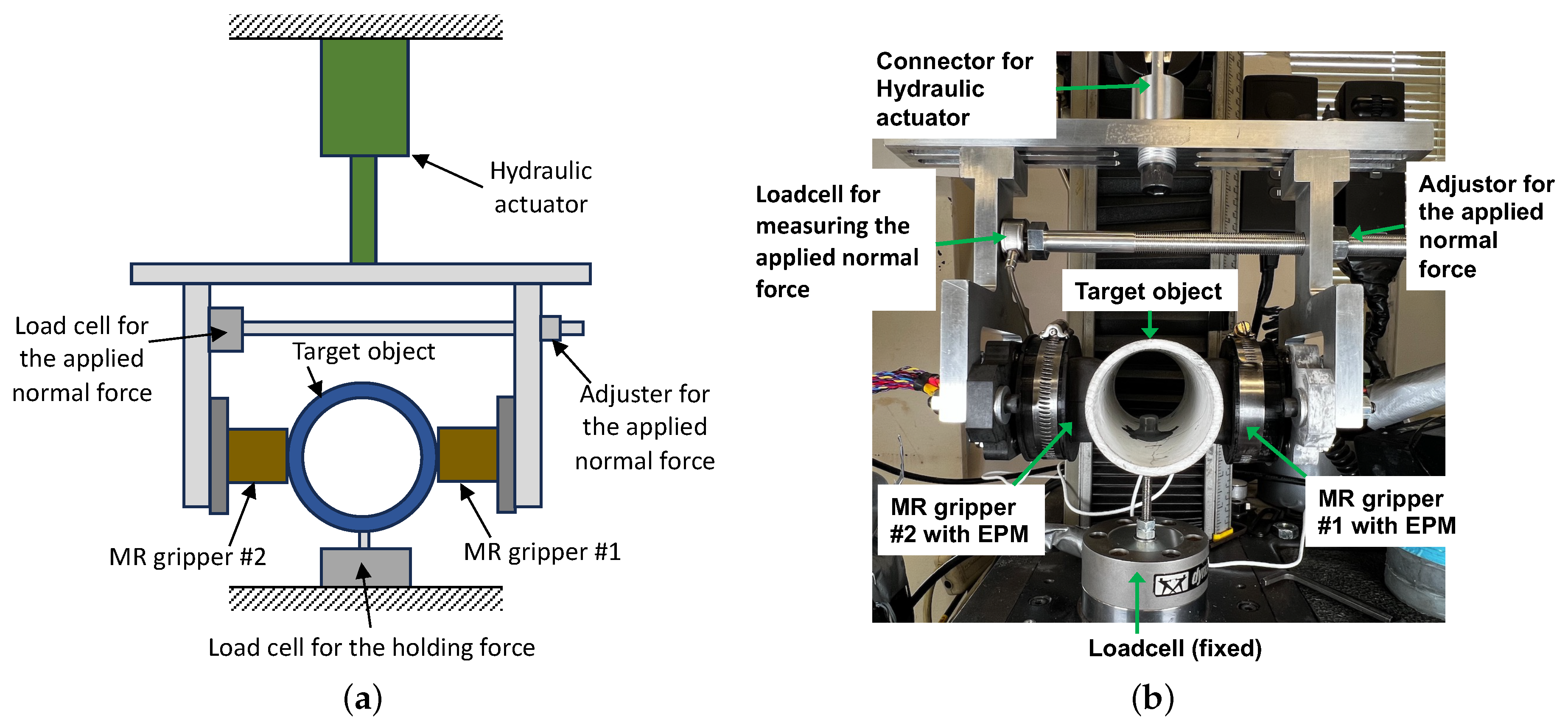
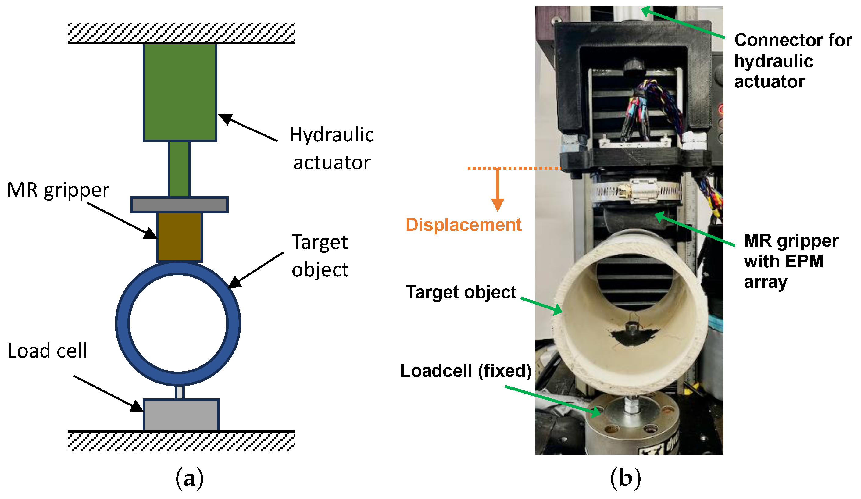
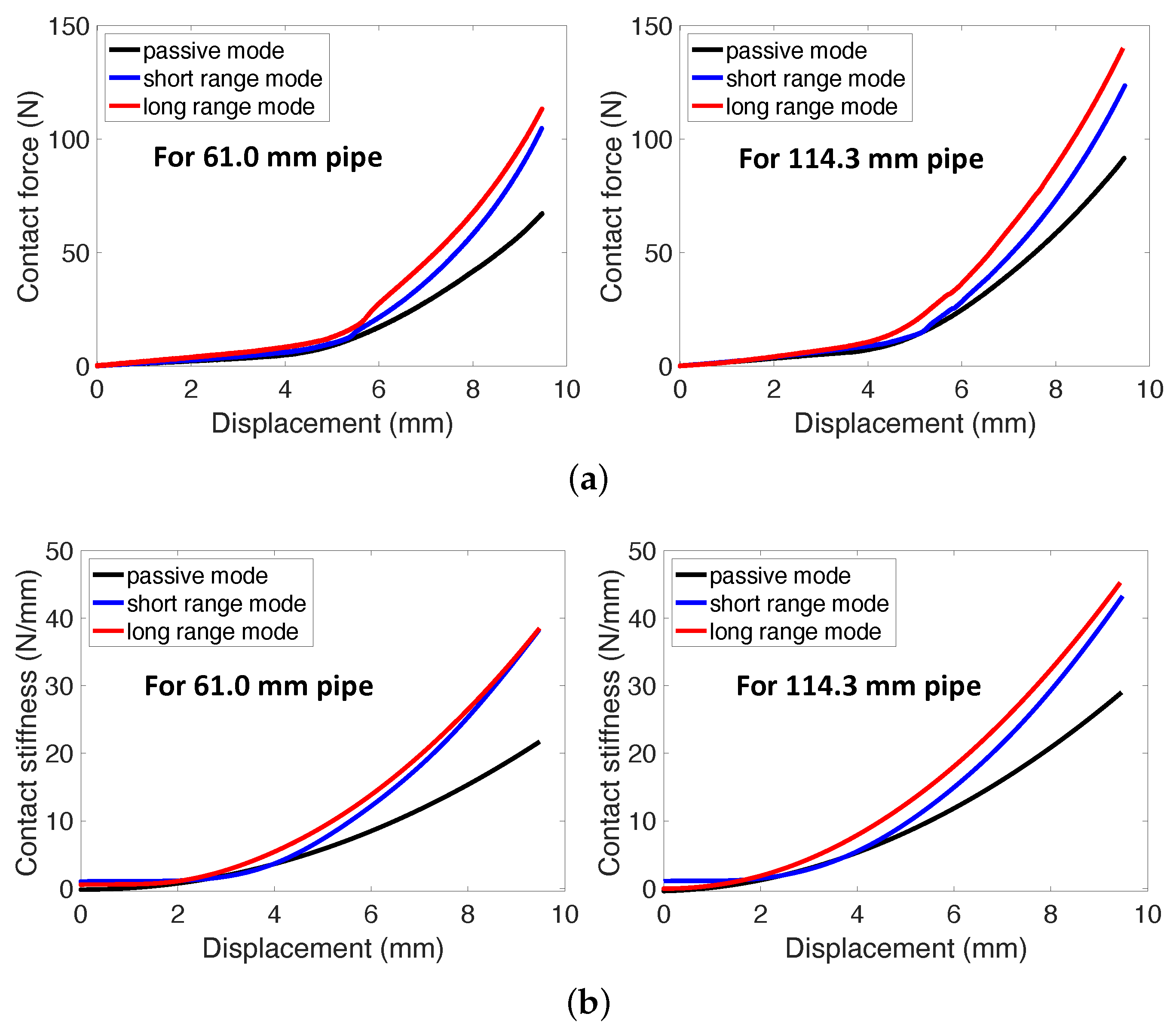
3. Measured Holding Performances of the MRF-Based Robotic Claw

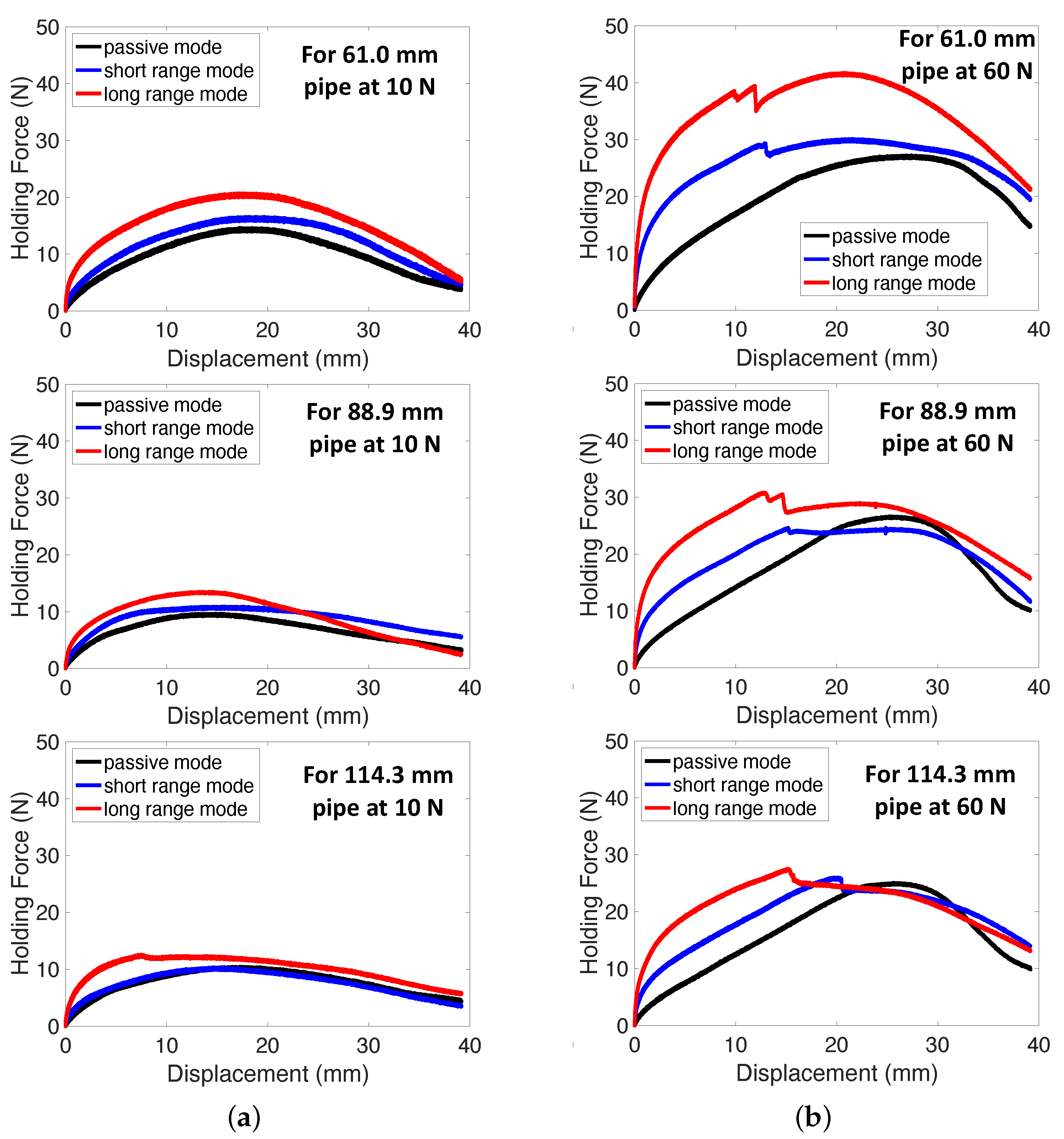
Figure 7 presents the measured holding forces of the MRF-based robotic claw with the EPM array versus the displacement at two different applied normal forces (i.e., 10 N and 60 N). As seen in this figure, the holding forces of the MRF-based robotic claw increased with the increased displacement. But, after a certain displacement point, the holding forces started to slowly decrease. The decline in holding forces resulted from the central sections of the MR grippers sliding up the center of the target object, causing a reduction in the contact area between the target object and the MRE bladders. In this study, the dynamic and static holding forces were used as the performance evaluation indices of the MRF-based robotic claw and were quantified via
F h , d = F h at z = 7 m m , F h , s = F h at z = 0.5 m m
Here, F h , d is the dynamic holding force, F h , s is the static holding force, F h is the holding force, and z is the vertical displacement of the MRF-based robotic claw, respectively. In this case, z = 7 mm for the dynamic holding force was selected as the maximum displacement, where the holding forces of all tested cases continuously increased without holding force jittering. Also, z = 0.5 
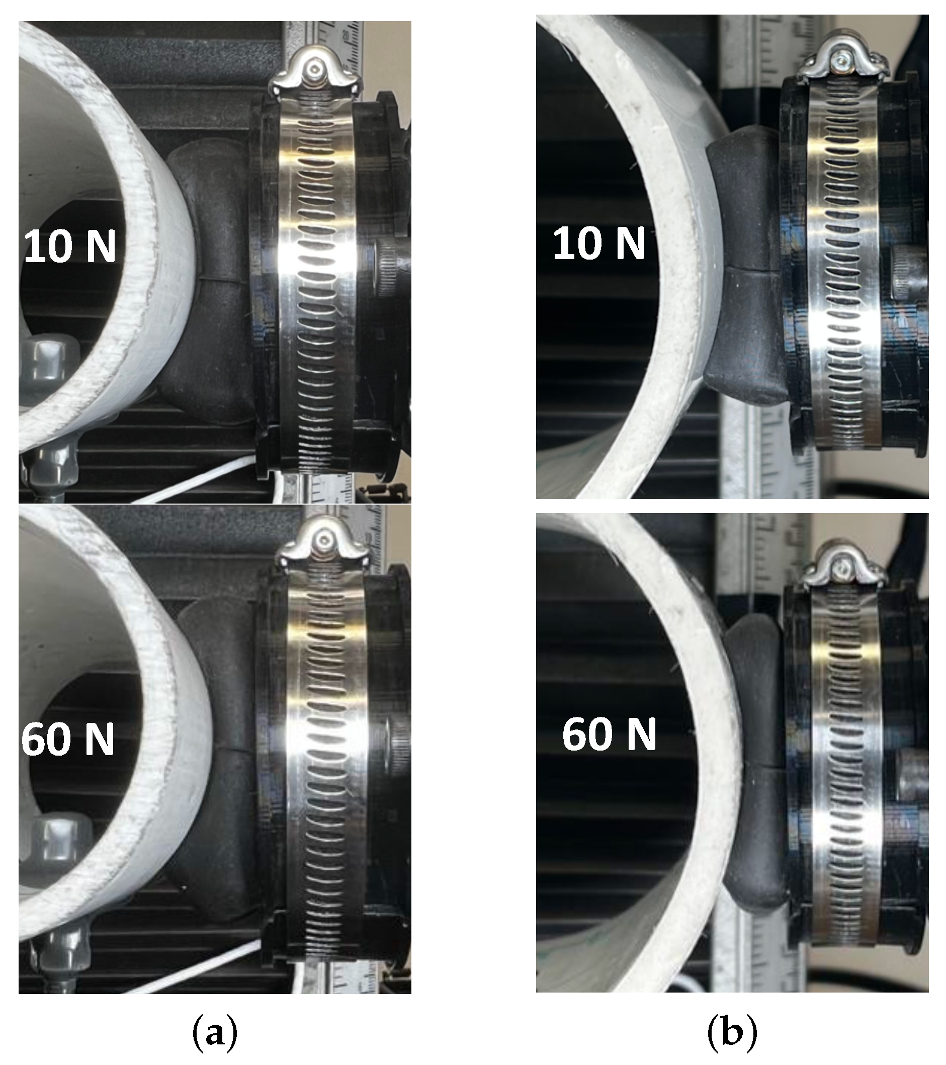
mm for the static holding force was selected by assuming the pick-and-placement accuracy of the MRF-based robotic claw. The dynamic holding force physically represents the maximum effective force exerted by the MRF-based robotic claw before the target object is released from its grip. On the other hand, the static holding force denotes the maximum effective force applied by the MRF-based robotic claw before the object begins to slip. It is important to highlight that the criteria for defining dynamic and static holding forces can be adjusted based on the intended purpose of employing the robotic claw. On the other hand, the holding forces of the MRF-based robotic claw were significantly changed by three different operation modes of the EPM array. The LR mode case could produce a higher holding force than the cases of the other operating modes. This phenomenon is because the magnetic flux in the LR mode could travel a longer distance from the top face of the EPM array than that in the SR mode. As a result, more portions of the MRF inside the bladders of the MR grippers could be energized by the EPM array in the LR mode than those in the SR mode. On the other hand, the applied normal force also significantly affected the holding forces of the MRF-based robotic claw. The holding forces of the MRF-based robotic claw at an applied normal force of 60 N were much larger than those at an applied normal force of 10 N. This is because the gripping action of the MRF-based robotic claw results from the friction between the bladders and the object. At an applied normal force of 10 N, the holding force difference between the three operating modes of the EPM array was small. But, at an applied normal force of 60 N, the holding force difference of the MRF-based robotic claw due to the three operating modes was relatively large. Also, these additional holding force increments by the SR and LR modes from the passive mode (i.e., no magnetic field) are due to the constraint of the hardened bladders of the MR grippers due to the MR effect. This can be observed from the photographs of the bladder shapes of the MRF-based robotic claw shown in Figure 8. As seen in this figure, the bladder of the MR gripper was elastically deformed by the object’s shape. The deformed amounts of the bladder were dependent on the applied normal forces. The larger the applied normal force, the more the bladder was deformed. The bladder was pushed by the object at the condition where the center of the MR gripper was initially aligned with the center of the object, and thus the edges’ shapes of the bladder were almost symmetric from the bladder center, as shown in Figure 8. Also, when the bladder was deformed, its center was closer to the top surface of the EPM array and its edges were bulged. Because of this phenomenon, some portions of the object can be entrapped inside the bladder, and the bulged edges of the bladder work as the constraint preventing the object to drop. If the bladder is hardened by the energized MRF, this constraint will be also strong, thereby considerably increasing the holding force of the MRF-based robotic claw from the passive mode case. Because of this fact, the SR and LR modes cases could produce greater holding forces than the passive mode case.
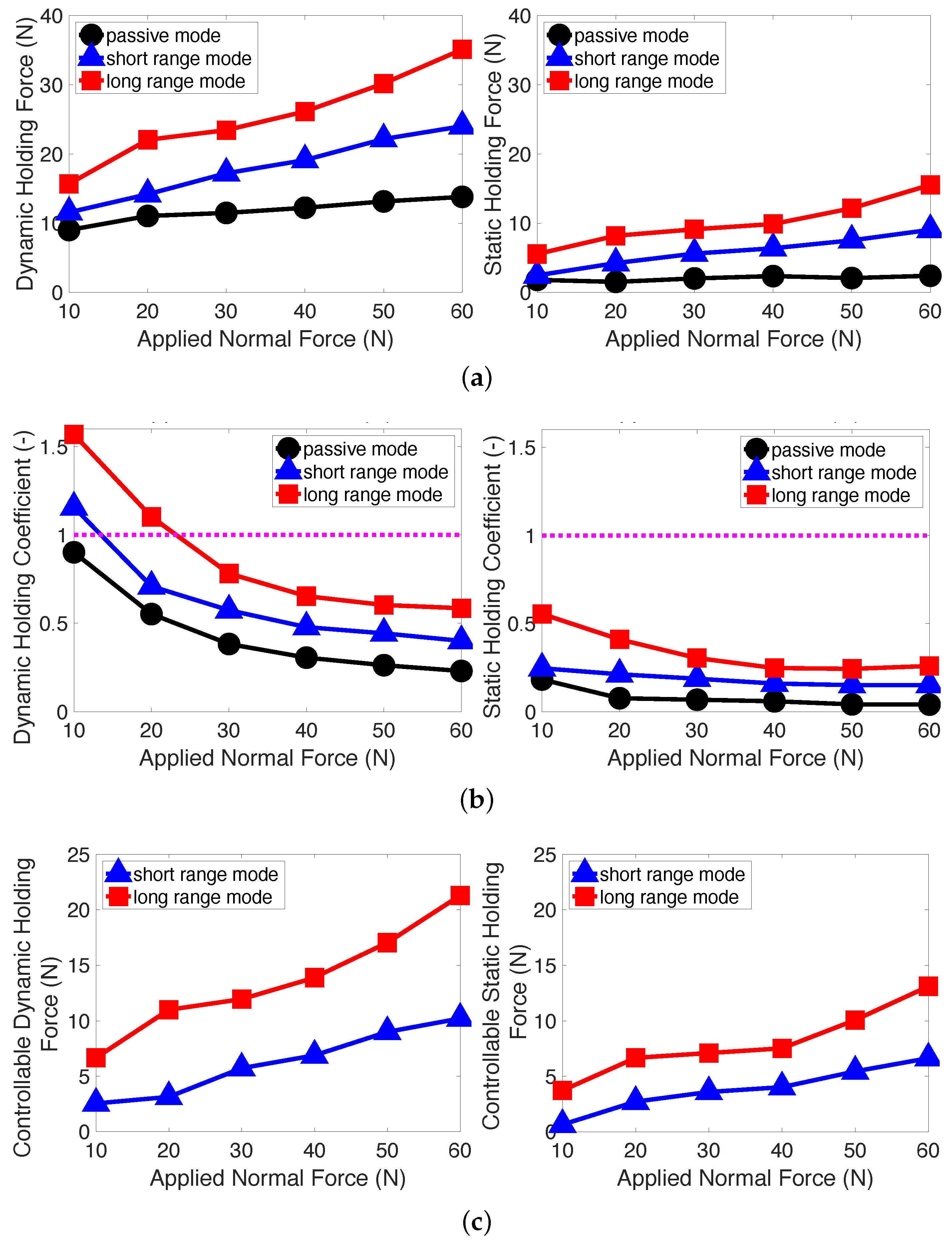
Figure 9 presents the holding performance of the MRF-based robotic claw with the EPM array versus the applied normal force for the 61.0 mm pipe. In this case, the dynamic and static holding forces were determined via the criteria of Equation (1). Also, the dynamic and static holding coefficients were determined via
μ d = F h , d F a and μ s = F h , s F a
Here, μ d is the dynamic holding coefficient, μ s is the static holding coefficient, and F a is the applied normal force. A higher holding coefficient indicates either improved holding force at the same applied normal force or the same holding force at a reduced applied normal force. Also, the controllable dynamic and static holding forces were determined via
Δ F h , d = F h , d | S R o r L R F h , d | p a s s i v e , Δ F h , s = F h , s | S R o r L R F h , s | p a s s i v e
Here, Δ F h , d is the controllable dynamic holding force and Δ F h , s is the controllable static holding force. Physically, the controllable dynamic and static holding forces mean the ranges of the additional dynamic and static holding forces that can be controlled by the SR and LR modes of the EPM array. As seen in Figure 9a, the dynamic holding forces were much larger than the static holding forces because the dynamic holding forces were determined at the status where the MRF-based robotic claw slid up the object further. As expected, the applied normal force continuously increased the dynamic and static holding forces. At all the applied normal forces tested here, the LR mode case could produce larger dynamic and static holding forces than the SR mode case. The maximum dynamic and static holding forces in the LR mode occurred at an applied normal force of 60 N because the object was closer to the EPM array’s top surface and the contact curvature of the bladder was larger at a higher applied normal force, as already observed in Figure 8a. The maximum dynamic and static holding forces at an applied normal force of 60 N were 35 N and 16 N, respectively. In the SR mode, the maximum dynamic and static holding forces also occurred at an applied normal force of 60 N, and they were 24 N and 9 N, respectively. In the passive mode, the maximum dynamic and static holding forces were 14 N and 2 N, respectively. On the other hand, as shown in Figure 9b, the dynamic and static holding coefficients decreased with the increased applied normal forces. At the low applied normal forces of less than 20 N, the dynamic holding force in the LR mode was larger than 1. This physically means that the dynamic holding force of the robotic claw at an applied normal force of less than 20 N was larger than the applied normal force. Also, this can imply that the MRF-based robotic claw is able to grasp a wider range of delicate or fragile objects with less damage or bruises. The maximum dynamic and static holding coefficient occurred at an applied normal force of 10 N. This trend is the opposite of the trend of Figure 9a. In the LR mode, the maximum dynamic and static holding coefficients were 1.6 and 0.6, respectively. In the SR mode, they were 1.2 and 0.25, respectively. In the passive mode, they were 0.9 and 0.2, respectively. On the other hand, the controllable dynamic and static holding forces almost linearly increased with the increased applied normal forces. Compared to the SR mode, the controllable dynamic and static holding forces in the LR mode were almost twice as large. The maximum controllable dynamic and static holding forces in the LR mode occurred at an applied normal force of 60 N, and they were 21 N and 14 N, respectively. In the SR mode, they were 10 N and 7 N, respectively.
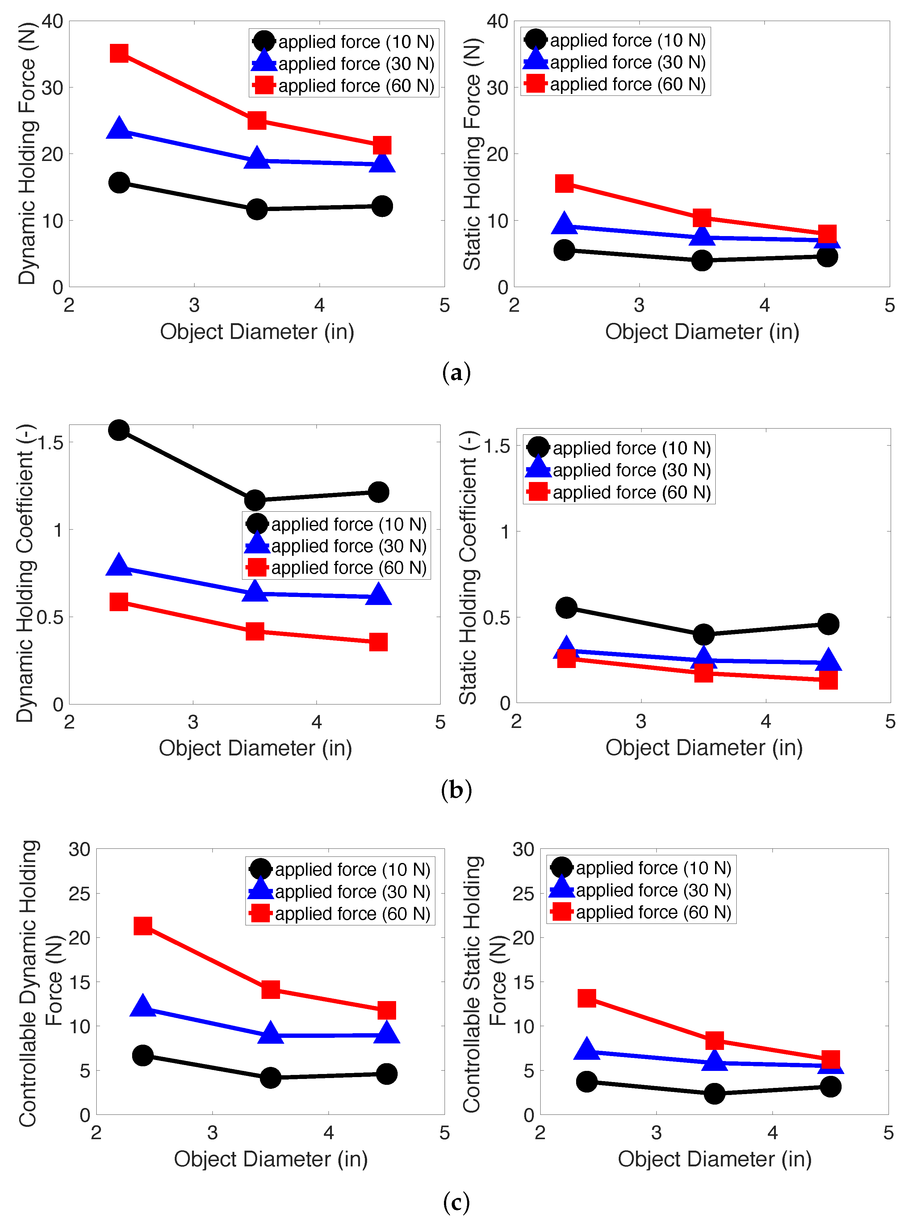
Figure 10 presents the holding performance of the MRF-based robotic claw with the EPM array in the LR mode versus the object size at three different applied normal forces (10 N, 30 N, and 60 N). As seen in Figure 10a, the dynamic and static holding forces almost continuously decreased with the increased object diameter for almost all applied forces tested here. This phenomenon is because when the diameter of the object increased, the bulged edges and contact curvatures of the bladder became smaller, as already seen in Figure 8. This can cause a decrease in the dynamic and static holding forces of the MRF-based robotic claw at a larger object diameter. At an applied normal force of 60 N, the dynamic and static holding forces for the 61.0 mm (2.4”) pipe were 35 N and 16 N, respectively. But, for the 114.3 mm (4.5”) pipe, the dynamic and static holding forces decreased to 21 N and 5 N, respectively. Similar to the trend of the dynamic and static holding forces in Figure 10a, both the holding coefficients in Figure 10b and the controllable holding forces in Figure 10c also decreased with the increased object diameter for most of the applied normal force cases. At an applied normal force of 10 N, the dynamic and static holding coefficients for the 61.0 mm pipe were 1.6 and 0.6, respectively. For the 114.3 mm pipe, the dynamic and static holding coefficients decreased to 1.2 and 0.5, respectively. On the other hand, the controllable dynamic and static holding forces at an applied normal force of 60 N for the 61.0 mm pipe were 21 N and 13 N, respectively. For the 114.3 mm pipe, the controllable dynamic and static holding forces decreased to 12 N and 6 N, respectively.
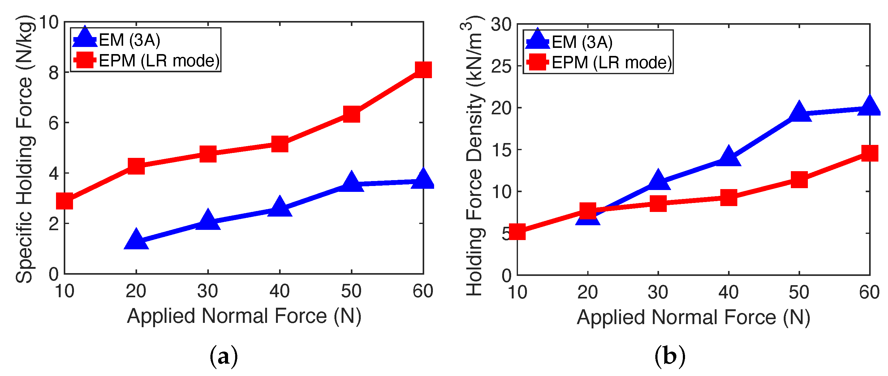
Figure 11 presents the comparison of the two different MRF-based robotic claws using the EM or the EPM array on the holding performance for the 61.0 mm pipe. First, as stated in the introduction, the holding performance of the MRF-based robotic claw using the conventional EM was reported in our prior study [16]. But, because of different device sizes and operating configurations, a direct comparison between the two different MRF-based robotic claws cannot be conducted. But, in aerospace and other engineering fields where stringent mass and volume constraints are imperative, there is a pronounced demand for devices that are both lighter and smaller. In light of this requirement, the holding performances of two different MRF-based robotic claws were compared. To this end, the specific holding force and the holding force density are proposed in this study as follows:
F s = F h , s | L R 2 M and F d = F h , s | L R 2 V
Here, F s is the specific holding force and F d is the holding force density. M and V are the mass and volume of the MR gripper, respectively. For the case of the MR gripper with the EPM array, the masses and volumes of both the MR gripper and the inhouse current amplifier (see 
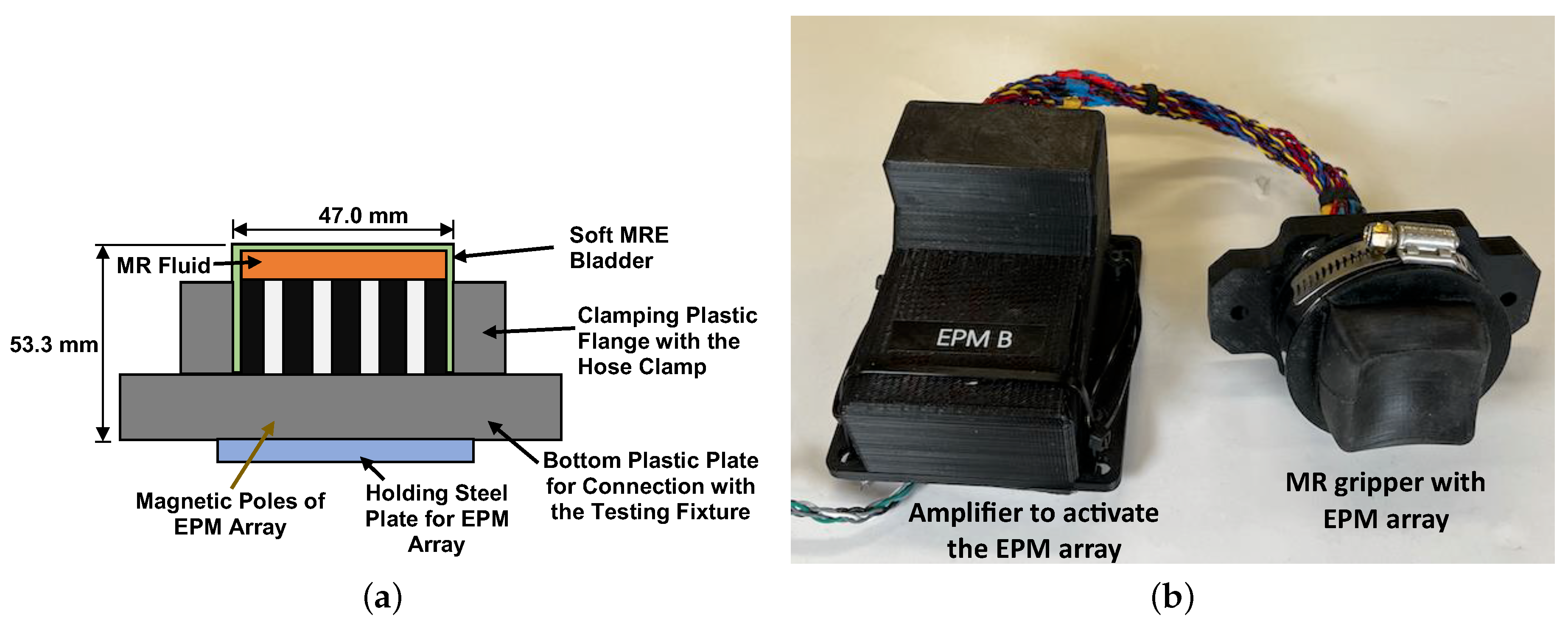
Figure 2b) to switch on and off the EPM array were considered. But, for the case of the MR gripper with the EM, a general-purpose, large, and hefty power supply was utilized. Thus, the mass and volume of this power supply were not factored into the determination of the specific holding force and holding force density. On the other hand, since the MRF-based robotic claws have two MR grippers, there is the number 2 in the denominator in Equation (4). Instead of using the dynamic holding force, the static holding force was used to determine both the specific holding force and holding force density because the static holding forces of two different MRF-based robotic claws were determined at the same displacement of z = 0.5 mm. As seen in Figure 11a, the MRF-based robotic claw with the EPM array in the LR mode could produce a larger specific holding force than the MRF-based robotic claw with the EM at a constant current input of 3 A (that result was obtained from our previous study [16]). But, for the holding force density shown in Figure 11b, the MRF-based robotic claw with the EPM array was better than the MRF-based robotic claw with the EM. This can imply that the MRF-based robotic claw with the EPM array may be better for the application required for lighter device weight and the MRF-based robotic claw with the EM may be better for the application required for less device volume.

4. Conclusions

In this study, the holding performance of an adaptive magnetorheological fluid (MRF)-based robotic claw operated with an electro-permanent magnet (EPM) array was addressed. To construct a two-finger type of MRF-based robotic claw, two magnetorheological (MR) grippers that consisted of MR elastomer (MRE) bladders and EPM arrays were configured at the end of each finger. A target object could be grasped by the normal force applied through these two MR grippers, and their contact stiffnesses could be also changed by activating the EPM array in three different operation modes: passive mode (i.e., no magnetic field), short-range (SR) mode (i.e, stronger on the magnet’s face but shorter magnetic flux travel ability), and long-range (LR) mode (i.e., longer magnetic flux travel ability). Because of those adaptive contact stiffness characteristics, the holding forces of the MRF-based robotic claw with the EPM array were changed by the operation modes of the EPM array at the same applied normal force. By using the testing setup constructed on the Instron material testing machine, the holding performances of the MRF-based robotic claw with the EPM array were experimentally evaluated. Three different diameter objects (i.e., 61.0 mm, 88.9 mm, and 114.3 mm) were tested as target objects, and the dynamic and static holding force, the dynamic and static holding coefficients, and the controllable dynamic and static holding forces were determined to evaluate the holding performance of the MRF-based robotic claw. Those holding performances of the MRF-based robotic claw could be increased with the EPM array, and the LR mode case could produce a better holding performance than the cases of the SR and passive modes. To compare the holding performances of two different MRF-based robotic claws using the EPM array or the conventional electromagnet (EM), the specific holding force and the holding force density were proposed and determined in this study. From this work, it was experimentally confirmed that the MRF-based robotic claw with the EPM array was very feasible for grasping a wider range of objects and could produce a better specific holding force than the MRF-based robotic claw with the conventional EM.

Author Contributions

Conceptualization: Y.C., K.D., M.J., C.H. and N.W.; Methodology: Y.C., C.H. and N.W.; Software: Y.C.; Validation: Y.C., C.H. and N.W.; Data Curation: Y.C.; Writing—original draft preparation: Y.C., N.W. and C.H.; writing—review and editing: Y.C., K.D., M.J., C.H. and N.W.; Resources: C.H. and M.J.; Supervision: M.J. and N.W.; Funding acquisition; C.H. and M.J. All authors have read and agreed to the published version of the manuscript.

Funding

Air Force Research Laboratory: Small Business Technology Transfer (STTR) Phase I Contract No. FA9453-22-C-A040 entitled “MR CLAW: Magneto-Rheological Capture, Locomotion, Anchoring, and Work-holding”.

Data Availability Statement

The data presented in this study are available on reasonable request from the corresponding author.

Conflicts of Interest

The authors report no conflict of interest.

References

  1. Xiang, C.; Guo, J.; Rossiter, J. Soft-Smart Robotic End Effectors with Sensing, Acutation, and Gripping Capabilities. Smart Mater. Struct. 2019, 28, 055034. [Google Scholar] [CrossRef]
  2. Tai, K.; El-Sayed, A.; Shahriari, M.; Biglarbegian, M.; Mahmud, S. State of the Art Robotic Grippers and Applications. Robotics 2016, 5, 11. [Google Scholar] [CrossRef]
  3. Ackerman, E. Here’s How NASA Will Grab an Asteroid Using a Spike Robot Gripper, 2015. IEEE Spectrum, 18 June 2015. Available online: https://spectrum.ieee.org/heres-how-nasa-will-grab-an-asteroid (accessed on 8 December 2023).
  4. Zheng, Y.; Lei, G.; Zhang, M.; Che, Q. Mechanical Design and Analysis of a Gripper for Noncooperative Target Capture in Space. Adv. Mech. Eng. 2018, 10, 1–11. [Google Scholar] [CrossRef]
  5. Mazzeo, A.; Aguzzi, J.; Calisti, M.; Canese, S.; Vecchi, F.; Stefanni, S.; Controzzi, M. Marines Robotics for Deep-Sea Specimen Collection: A Systematic Review of Underwater Grippers. Sensors 2022, 22, 648. [Google Scholar] [CrossRef] [PubMed]
  6. Hernandez, J.; Sunny, M.; Sanjuan, J.; Rulik, I.; Zarif, M.; Ahamed, S.; Ahmed, H.; Rahman, M. Current Designs of Robotic Arm Grippers: A Comprehensive System Review. Robotics 2023, 12, 5. [Google Scholar] [CrossRef]
  7. Tawk, C.; Mutlu, R.; Alici, G. A 3D Printed Modular Soft Gripper Integrated with Metamaterials for Conformal Grasping. Front. Robot. 2022, 8, 799230. [Google Scholar] [CrossRef] [PubMed]
  8. Xu, W.; Zhang, H.; Yuan, H.; Liang, B. A Compliant Adaptive Gripper and Its Intrinsic Force Sensing Method. IEEE Trans. Robot. 2021, 37, 1584–1603. [Google Scholar] [CrossRef]
  9. Pettersson, A.; Davis, S.; Gray, J.; Dodd, T.; Ohlsson, T. Design of a magnetorheological robot gripper for handling of delicate food products with varying shapes. J. Food Eng. 2010, 98, 332–338. [Google Scholar] [CrossRef]
  10. Liu, Q.; Jing, T.; Mo, A.; Xu, X.; Zhang, W. A Novel Robot Hand with the Magneto-Rheological Fluid Solidification. In Proceedings of the 2015 IEEE Conference on Robotics and Biomimetrics, Zhuhai, China, 6–9 December 2015. [Google Scholar] [CrossRef]
  11. Nishida, T.; Okatani, Y.; Tadakuma, K. Development of Universal Robot Gripper Using MRα Fluid. Int. J. Humanoid Robot. 2016, 13, 1650017. [Google Scholar] [CrossRef]
  12. Choi, Y.T.; Hartzell, C.M.; Wereley, N.M.; Leps, T.J.G. Gripping characteristics of an electromagnetically activated magnetorheological fluid-based gripper. AIP Adv. 2018, 8, 056701. [Google Scholar] [CrossRef]
  13. Hartzell, C.M.; Choi, Y.T.; Wereley, N.M.; Leps, T.J.G. Performance of a magnetorheological fluid-based robotic end effector. Smart Mater. Struc. 2019, 8, 035030. [Google Scholar] [CrossRef]
  14. Bernat, J.; Gajewski, P.; Kapela, R.; Marcinkowsk, A. Design, Fabrications and Analysis of Magnetorheological Soft Gripper. Sensors 2022, 22, 2757. [Google Scholar] [CrossRef] [PubMed]
  15. Guan, R.; Zheng, H.; Liu, Q.; Ou, K.; Li, D.S.; Fan, J.; Fu, Q.; Sun, Y. DIW 3D Printing of Hybrid Magnetorheological Materials for Application in Soft Robotic Grippers. Compos. Sci. Technol. 2022, 223, 109409. [Google Scholar] [CrossRef]
  16. Choi, Y.T.; Hartzell, C.M.; Wereley, N.M. Holding Performance of the an Adaptive Magnetorheological Fluid-Based Robotic Claw. IEEE Trans. Magn. 2023, 59, 4600705. [Google Scholar] [CrossRef]
  17. Tumanski, S. Handbook of Magnetic Measurements; CRC Press: Boca Raton, FL, USA, 2011. [Google Scholar]
Figure 1. Schematic for the working principle of the electro-permanent magnet (EPM).
Actuators 12 00469 g001
Figure 2. Magnetorheological (MR) gripper with the EPM array. (a) Schematic, (b) photo.
Actuators 12 00469 g002
Figure 3. The measured magnetic flux density of the MR gripper with the EPM array at different operating modes. (a) In the SR mode, (b) in the LR mode.
Actuators 12 00469 g003
Figure 4. Experimental testing setup for the measurement of the contact force of the MR gripper with the EPM array. (a) Schematic, (b) photograph.
Actuators 12 00469 g004
Figure 5. The contact force and contact stiffness of the MR gripper with the EPM array versus the displacement. (a) Contact force, (b) contact stiffness.
Actuators 12 00469 g005
Figure 6. MRF-based robotic claw with the EPM array and its testing setup for the holding force measurement. (a) Schematic, (b) photograph.
Actuators 12 00469 g006
Figure 7. The holding forces of the MRF-based robotic claw with the EPM array versus the displacement at two different applied normal forces (i.e., 10 N and 60 N). (a) At an applied normal force of 10 N, (b) at an applied normal force of 60 N.
Actuators 12 00469 g007
Figure 8. The bladder shapes of the MRF-based robotic claw with the EPM array at different applied normal forces (i.e., 10 N and 60 N). (a) For the 61.0 mm pipe, (b) for the 114.3 mm pipe.
Actuators 12 00469 g008
Figure 9. The holding performance of the MRF-based robotic claw with the EPM array versus the applied normal force for the 61.0 mm pipe. (a) Dynamic and static holding forces, (b) dynamic and static holding coefficients, (c) dynamic and static controllable holding forces.
Actuators 12 00469 g009
Figure 10. The holding performance of the MRF-based robotic claw with the EPM array in the LR mode versus the object size at three different applied normal forces (10 N, 30 N, and 60 N). (a) Dynamic and static holding forces, (b) dynamic and static holding coefficients, (c) dynamic and static controllable holding forces.
Actuators 12 00469 g010
Figure 11. Comparison of the two different MRF-based robotic claws using the electromagnet (EM) or EPM array on the holding performance for the 61.0 mm pipe. (a) Specific holding force, (b) holding force density.
Actuators 12 00469 g011
Disclaimer/Publisher’s Note: The statements, opinions and data contained in all publications are solely those of the individual author(s) and contributor(s) and not of MDPI and/or the editor(s). MDPI and/or the editor(s) disclaim responsibility for any injury to people or property resulting from any ideas, methods, instructions or products referred to in the content.

