Article

Disturbance Observer-Based Adaptive Fault Tolerant Control with Prescribed Performance of a Continuum Robot

Institute of Logistics Science and Engineering, Shanghai Maritime University, Shanghai 201306, China
Actuators 2024, 13(7), 267; https://doi.org/10.3390/act13070267
Submission received: 11 June 2024 / Revised: 10 July 2024 / Accepted: 11 July 2024 / Published: 14 July 2024
(This article belongs to the Section Actuators for Robotics)

Abstract

:
This paper studies an adaptive fault tolerant control (AFTC) scheme for a continuum robot subjected to unknown actuator faults, dynamics uncertainties, unknown disturbances, and prescribed performance. Specifically, to deal with uncertainties, a function approximation technique (FAT) is employed to evaluate the unknown actuator faults and uncertain dynamics of the continuum robot. Then, a nonlinear disturbance observer (DO) is developed to estimate the unknown compounded disturbance, which contains the unknown disturbances and approximation errors of the FAT. Furthermore, the prescribed error bound is treated as a time-varying constraint, and the controller design method is based on an asymmetric barrier Lyapunov function (BLF), which is operated to strictly ensure the steady-state and transient performance of the continuum robot. Afterwards, the simulation results validate the effectiveness of the proposed AFTC in dealing with the unknown actuator faults, uncertainties, unknown disturbances, and prescribed performance. Finally, the effectiveness of the proposed AFTC scheme is verified through experiments.

1. Introduction

Continuum robots are a new type of robot inspired by octopus tentacles and elephant trunks [1]. Continuum robots have resilient structures which supply them with amusing abilities such as flexibility and shape resumption. Continuum robots can fit into sophisticated environments and are popularly used in practice, such as in aeroengine maintenance, nuclear reactor maintenance, minimally invasive surgery, and so on [2]. However, compared with the conventional rigid robots, the dynamics of the continuum robots form a strongly nonlinear system. Thus, it is laborious to acquire the accurate dynamics expression of continuum robots [3]. Furthermore, owing to the flexibility of the continuum robots, the tracking performance will be severely affected when the continuum robots endure actuator faults and external disturbances [4]. Therefore, it is an immensely challenging task to study the fault-tolerant tracking control of the continuum robots [5,6,7].
In the literature, several fault tolerant control (FTC) methods have been developed to assure the tracking performance of the robot is maintained when subjected to actuator faults; these methods may be typically parted into passive and active FTC [8,9]. For active FTC, the controller leans upon the fault detection and diagnosis (FDD) methods which chiefly involve model-based and model-free methods [10]. However, the model-based FDD method needs to know the precise dynamics of the robot. Furthermore, the model-free FDD method is mostly stemmed from measured data, so the fault detection may not be reliable and may increase the computational burden [11]. On the contrary, for passive FTC, no feedback is required in controller design for the regular and fault manipulation [12]. Although the passive FTC methods are easy to implement, they entail the operator to be aware and to have an a priori know-how of faults. Furthermore, over the past few years, numerous smart passive FTC methods have been developed to counteract actuator faults [13]. However, for the smart passive FTC methods, the fault tolerance function which was merely set by a known constant is considered without uncertainties and disturbances [14]. Furthermore, the research on FTC for the continuum robot is marginally reported in the literature. Thus, more general passive FTC problems related to continuum robots, such as uncertainties, disturbances, and actuator faults, need to be further researched [15,16].
For the uncertainties, an adaptive control utilizing a fuzzy logic system (FLS) or neural network (NN) is an efficacious method to overcome this problem [17,18,19]. An adaptive controller was proposed for the nonlinear systems using FLS [20]. Considering the actuator dynamics, an adaptive constrained controller based on FLS was developed for hypersonic vehicles [21]. An adaptive NN controller was proposed for the mechanisms with an unknown dead zone [22]. To improve robustness, an adaptive switching controller utilizing NN was presented for a dynamic system [23]. Considering the unknown parameters, an adaptive fuzzy compensation control scheme was proposed for flexible joint robots [24]. FLS and NN mainly have a good approximation ability to continuous function, but a poor approximation ability to discontinuous function. Furthermore, in practical applications for the robot, the actuator faults may be discontinuous. Therefore, for these cases, FLS and NN will provide a large estimation error and poor approximation performance. Fortunately, a function approximation technique (FAT) employing Fourier series (FS) expansions or Legendre polynomials (LP) was proposed for unknown functions, which has a good approximation capability for continuous and discontinuous functions [25]. A FAT-based adaptive controller was proposed for the nonidentical systems [26]. Compared with the fuzzy control and NN control methods, the FAT-based adaptive control approach is simpler and has less computation, since there are fewer tuning parameters [25,27]. However, the above-mentioned approximation approaches possess good approximation performance for the functions of the system mode and control input, and offer a large approximation error and weak approximation performance for unknown external disturbances.
To deal with the issue of unknown disturbances, an estimation technique based on the disturbance observer (DO) is developed [28]. An integral DO was designed to efficaciously estimate the total disturbance and raise the estimation accuracy [29]. A DO-based attitude tracking control approach was proposed for the reusable launch vehicles [30]. Considering the input lag of nonlinear systems, a partitioned switching nonlinear DO was exercised to estimate the unknown composite disturbance for a switched uncertain system, which itself improved the stability of the systems [31]. Furthermore, an adaptive fuzzy control approach integrated with an additional torque input by using a DO was proposed, which was designed for the robotic exoskeleton [32]. A DO-based boundary adaptive control approach was proposed to restrain the deflection of a flexible robot, realize angular positioning, and hold-up unknown disturbances [33]. Nevertheless, the methods mentioned above do not consider the prescribed performance.
The excellent dynamic performance of the robot is gradually receiving attention, and its main characteristics are precision demands and response speed [34]. The prescribed performance control (PPC) is an effectual manner in which to surmount issues that the robot faces [35]. A tracking PPC scheme was designed for input-saturated spacecraft [36]. Considering the jumps of uncertain parameters, a neural PPC with the filtered term was designed for uncertain systems [37]. Moreover, considering the input constrictions, a PPC approach was presented for the unmanned surface vessel; the restricted system with inequality strictures is changed into the system with equality strictures using the barrier Lyapunov function (BLF) [38]. An adaptive fuzzy observer-based controller using the BLF was developed for a nonlinear system [39]. Nevertheless, the transient response of the BLF-based control mentioned above is tardy, the convergence speed is poor, the control signal is prone to chattering, and the transient and steady-state performance has not been considered simultaneously.
On account of the above discussions, numerous research achievements on actuator faults, uncertainties, disturbances, and prescribed performance have been reported. However, to the author’s knowledge, at least up to now, there are few reported cases from the literature on FTC for the continuum robot subjected to actuator faults, uncertainties, disturbances, and prescribed performance simultaneously. Furthermore, the precise dynamics of the continuum robots are difficult to obtain. Additionally, due to the flexibility of the continuum robot, the tracking performance will be greatly affected by actuator faults and external disturbances. Thus, how to achieve FTC with the prescribed performance for the continuum robot remains an open issue, particularly due to the existence of the unknown actuator faults, uncertain dynamics, and unknown disturbances. Motivated by solving this problem, this paper presents a novel adaptive FTC (AFTC) scheme combined with BLF, FAT, and DO to simultaneously handle unknown actuator faults, model uncertainties, and unknown disturbances for the continuum robot. The main contributions of this paper are summarized as follows:
(1)
Compared with the conventional prescribed performance results, in this paper, an asymmetric time-varying BLF is applied for uncertain continuum robot systems to avert the tracking error contravening the time-varying constraint, which has a faster convergence speed and higher tracking accuracy.
(2)
A function approximation technique (FAT) is introduced to effectively evaluate the lumped unknown term of the continuum robot. The proposed FAT has a good capability to approximate the discontinuous and continuous unknown functions, respectively. Furthermore, FAT has less computation, since there are fewer tuning parameters.
(3)
In contrast with the traditional DO-based AFTC methods, a nonlinear DO is operated to estimate the new compounded disturbance, which can erase the disturbance quickly and offer higher estimation accuracy. Furthermore, no matter when actuator faults occur, the proposed controller of the continuum robot can evaluate the uncertain disturbance in real time and has a good control performance.

2. System Description and Problem Formulation

The continuum robot is constituted of a base disk, spacer disks, an end disk, and flexible NiTi backbones. To ease the analysis, it is supposed that the simplified bending model of the continuum robot is a circular arc, as shown in Figure 1. Point O is the center point of base disk, O x y z denotes the global coordinate, and O x c y c z c represents the bending plane coordinate [3,5]. θ stands for the angle of bending primary backbone in the O x c z c plane. The angle between the axis x and axis x c is defined as φ . In addition, i   ( i = 1 , 2 , 3 ) denotes the label of secondary backbone. r is the distance from the primary backbone to each secondary backbone on the disk. L is the length of the primary backbone [7]. The secondary backbone is the driving backbone, which makes the continuum robot actualize bending movement.
The simplified dynamics of the continuum robot can be described by [2,4]
M 0 ( q ) q ¨ + C 0 ( q , q ˙ ) q ˙ + G 0 ( q ) + Δ H ( q , q ˙ , q ¨ ) + d = F
where q = [ θ , φ ] T is the vector of the joint variable, M 0 ( q ) R 2 × 2 is the nominal inertia matrix, C 0 ( q , q ˙ ) R 2 × 2 denotes the nominal matrix of Coriolis and centripetal forces, G 0 ( q ) R 2 expresses the nominal gravity vector, d R 2 represents the external disturbance, and F = [ f 1 , f 2 ] T denotes the driving force. Δ H ( q , q ˙ , q ¨ ) denotes the uncertain dynamics of the continuum robot resulting from the uncertain inertia matrix Δ M ( q ) R 2 × 2 , uncertain Coriolis and centrifugal matrix Δ C ( q , q ˙ ) R 2 × 2 , uncertain gravitational torque Δ G ( q ) R 2 , and friction force F b ( q , q ˙ ) R 2 . The modality of Δ H ( q , q ˙ , q ¨ ) is as follows:
Δ H ( q , q ˙ , q ¨ ) = Δ M ( q ) q ¨ + Δ C ( q , q ˙ ) q ˙ + Δ G ( q ) + F b ( q , q ˙ )
Remark 1.
Since the continuum robot has two degrees of freedom, the configuration of the continuum robot can be determined by two driving forces. Moreover, the structure of the continuum robot is center symmetric about the primary backbone, so the driving forces f 1 , f 2 and f 3 are spatial center symmetric about the primary backbone. The continuum robot is driven by simultaneously pulling any two independent secondary backbones among the three secondary backbones. Equation (2) is based on the assumption that f 1 and f 2 are driving forces.
Property 1.
The matrix M 0 ( q ) is symmetric and positive definite, and matrix ( 1 / 2 ) M ˙ 0 ( q ) C 0 ( q , q ˙ ) is skew-symmetric [2].
Property 2.
There are positive scalars, 1 and 2 , such that 0 < 1 < λ min ( M 0 ( q ) ) M 0 ( q ) λ max ( M 0 ( q ) ) < 2 < , where M 0 ( q ) is the induced Frobenius norm of M 0 ( q ) . λ min ( ) and λ max ( ) denote the minimum and maximum eigenvalues of a matrix, respectively [7].
Lemma 1.
Suppose c b is a positive constant; if x R and | x | < c b , then the following inequality holds [2,13]
ln c b c b x 2 x 2 c a x 2
Lemma 2.
Suppose that there exists a continuous and positive function V ( x ) > 0 , such that its derivative satisfies
V ˙ ( x ) = c 1 V ( x ) + c 2
where c 1 and c 2 are positive constants. Then, the solution x ( t ) is uniformly bounded [7,13].
Assumption 1.
The external disturbance d is assumed to be continuous and bounded, satisfying d d ¯ , where d ¯ is a positive constant.
The model of one actuator fault is given by [13]
u i = ρ i u F , i + ς i ( t ) ,   i = 1 , 2
where ρ i expresses the gain fault factor of the i th joint actuator, and ς i ( t ) represents the bias force.
Thus, in light of (5), the fault model of all actuators for the continuum robot can be expressed by
u = ρ u F + ς ( t )
where u F = [ u F 1 , u F 2 ] T is the control input vector, ρ = diag [ ρ 1 , ρ 2 ] is the gain fault matrix, and ς ( t ) = [ ς 1 ( t ) , ς 2 ( t ) ] T is the bias force vector.
Assumption 2.
There is a constant ς ¯ > 0 such that ς ( t ) ς ¯ .
Denoting x 1 q and x 2 q ˙ , substituting (6) into (1), then the dynamics of (1) can be rewritten as
x ˙ 1 = x 2 x ˙ 2 = M 0 1 ( x 1 ) [ u F C 0 ( x 1 , x 2 ) x 2 G 0 ( x 1 ) Δ ξ d ]
where Δ ξ = [ ( I ρ ) u F ς ( t ) + Δ H ( x 1 , x 2 , x ˙ 2 ) ] means a new lumped unknown term with Δ ξ = [ Δ ξ 1 , Δ ξ 2 ] T , and I R 2 × 2 is an identity matrix.
The objective of this paper is to develop an AFTC scheme for the continuum robot with the actuator faults, uncertainties, external disturbances, and prescribed performance, so that the continuum robot can retain a good tracking performance.

3. Design of AFTC

3.1. Controller Design

Assuming that x 1 d is the desired position trajectory of the continuum robot and x 2 d = x ˙ 1 d , it is supposed that x 1 d and x 2 d satisfy | x i d | < x ¯ , i = 1 , 2 , and x ¯ > 0 is a constant.
e 1 = x 1 x 1 d
e 2 = x 2 η 1
where e 1 = [ e 11 , e 12 ] T , η 1 is a virtual control vector to be subsequently designed.
From (8), one has
e ˙ 1 = x ˙ 1 x ˙ 1 d
According to (9), it can be deduced that
e ˙ 2 = x ˙ 2 η ˙ 1 = M 0 1 ( x 1 ) [ u F C 0 ( x 1 , x 2 ) x 2 G 0 ( x 1 ) Δ ξ d ] η ˙ 1
The lower and upper time-varying constraints of e 1 are designed as
k b ( t ) = [ k b 1 ( t ) , k b 2 ( t ) ] T
k c ( t ) = [ k c 1 ( t ) , k c 2 ( t ) ] T
Then, this obtains
e 1 i [ k b i ( t ) , k c i ( t ) ] ,   i = 1 , 2
Introducing a BLF as
V 1 = i = 1 2 [ S ( e 1 i ) 2 ln k c i 2 ( t ) k c i 2 ( t ) e 1 i 2 + 1 S ( e 1 i ) 2 ln k b i 2 ( t ) k b i 2 ( t ) e 1 i 2 ]
where
S ( e 1 i ) = { 0 ,   e 1 i 0 1 ,   e 1 i > 0 ,   i = 1 , 2
Through coordinate transformation, one has
μ b i = e 1 i k b i ( t ) ,   μ c i = e 1 i k c i ( t )
Which defines
μ i = S ( e 1 i ) μ c i + ( 1 S ( e 1 i ) ) μ b i
Then, (15) can be expressed by
V 1 = 1 2 i = 1 2 ln 1 1 μ i 2
where μ i is set to | μ i | < 1 to assure that V 1 is positive.
Differentiating V 1 , and combining with (18), one has
V ˙ 1 = i = 1 2 ( μ i 1 μ i 2 )
= i = 1 2 [ S ( e 1 i ) μ c i ( 1 μ c i 2 ) k c i ( t ) ( η 1 i + e 2 i x ˙ 1 i d k ˙ c i ( t ) k c i ( t ) e 1 i ) ]
+ i = 1 2 [ ( 1 S ( e 1 i ) ) μ b i ( 1 μ b i 2 ) k b i ( t ) ( η 1 i + e 2 i x ˙ 1 i d k ˙ b i ( t ) k b i ( t ) e 1 i ) ]
Selecting the virtual controller η 1 as
η 1 = ( K 1 + Λ 1 ) e 1 + x ˙ 1 d
where K 1 = diag [ k 11 , k 12 ] is a positive-definite gain matrix, and Λ 1 = diag [ Λ 11 , Λ 12 ] with
Λ 1 i = χ s + ( k ˙ b i ( t ) k b i ( t ) ) 2 + ( k ˙ c i ( t ) k c i ( t ) ) 2
and χ s is a positive constant.
Remark 2.
Compared with the available prescribed performance outcomes, in this paper, a proper asymmetric time-varying BLF is employed for uncertain continuum robot systems to impede the tracking error contravening a time-varying constraint, which has a faster convergence speed and a higher tracking accuracy. Furthermore, the proposed prescribed performance function can assure that the tracking error converges to an arbitrary small region. Meanwhile, the proposed prescribed performance function can ensure a good steady-state performance of the continuum robot and also achieve a good system transient tracking performance. However, this is a shortcoming of the existing results using exponential-prescribed performance function.
Substituting (21) and (22) into (20) yields
V ˙ 1 = i = 1 2 S ( e 1 i ) μ c i ( 1 μ c i 2 ) k c i ( t ) [ e 2 i ( Λ 1 i + k ˙ c i ( t ) k c i ( t ) ) e 1 i k 1 i e 1 i ]
+ i = 1 2 ( 1 S ( e 1 i ) ) μ b i ( 1 μ b i 2 ) k b i ( t ) [ e 2 i ( Λ 1 i + k ˙ b i ( t ) k b i ( t ) ) e 1 i k 1 i e 1 i ]
i = 1 2 λ i e 1 i e 2 i i = 1 2 μ 1 2 1 μ 1 2 k 1 i
where
λ i = i = 1 2 ( S ( e 1 i ) k c i 2 ( t ) e 1 i 2 + 1 S ( e 1 i ) k b i 2 ( t ) e 1 i 2 )
and λ = diag [ λ 1 , λ 2 ] .
According to FAT, the lumped unknown term Δ ξ can be expressed by
Δ ξ = W * T φ ( Z ) + ε Z
where W * = [ w 1 * , w 2 * , , w n * ] is the ideal weight, Z = [ x 1 , , x 2 , ρ , ς ] T is the input variable, φ ( Z ) = [ φ 1 ( Z ) , φ 2 ( Z ) , , φ n ( Z ) ] T is the basis function, and ε Z is the estimation error.
The adaption law is designed as
w ^ ˙ i = Γ i [ φ i ( Z ) e 2 i + γ i | e 2 i | w ^ i ]
where w ^ i   ( i = 1 , 2 , , n ) denotes the actual weight which is used to estimate w i * , Γ i > 0 is a constant, and γ i > 0 is a small constant.
Defining a compounded disturbance as
δ = d + ε Z
where δ and δ ˙ are bounded, and | δ ˙ | 1 with a constant 1 .
Defining the control law as
u F = W ^ T φ ( Z ) λ e 1 K 2 e 2 + C 0 ( x 1 , x 2 ) η 1 + G 0 ( x 1 ) + M 0 ( x 1 ) η ˙ 1 + δ ^
where K 2 = diag [ k 21 , k 22 ] is a positive-definite gain matrix.
Substituting (25) into (11) obtains
e ˙ 2 = M 0 1 ( x 1 ) [ u F C 0 ( x 1 , x 2 ) x 2 G 0 ( x 1 ) δ W * T φ ( Z ) ] η ˙ 1
Remark 3.
Traditional AFTC approaches utilizing an FLS and NN have a good approximation performance to continuous functions but poor approximation ability to discontinuous functions [20,21,22,23]. However, in practical applications for the continuum robot, the abrupt and intermittent faults of the actuators may be discontinuous. For these cases, traditional an FLS and NN will provide a large estimation error and poor approximation performance. Compared with traditional an FLS and NN, the proposed FAT has a good ability to approximate discontinuous and continuous unknown functions, respectively. Thus, in this paper, FAT is applied to evaluate Δ ξ , which gathers the unknown and uncertain dynamics, frictions, and actuator faults of the continuum robot.
To compensate the disturbance, a nonlinear DO is adopted to estimate the compounded disturbance δ . Introducing an auxiliary variable as
e 3 = δ Ψ ( e 2 )
where a nonlinear function Ψ ( e 2 ) is designed.
Taking the derivative of (30), one has
e ˙ 3 = d ˙ Λ ( e 2 ) e ˙ 2 = d ˙ Λ ( e 2 ) M 0 1 ( x 1 ) [ u F C 0 ( x 1 , x 2 ) x 2 G 0 ( x 1 ) δ M 0 ( x 1 ) η ˙ 1 W * T φ ( Z ) ]
where the nonlinear matrix Λ ( e 2 ) = ( Ψ ( e 2 ) ) / ( e 2 T ) is designed.
To obtain the disturbance estimate value, the estimate e ^ 3 is given by
e ^ ˙ 3 = Λ ( e 2 ) M 0 1 ( x 1 ) [ u F C 0 ( x 1 , x 2 ) x 2 G 0 ( x 1 ) δ ^ M 0 ( x 1 ) η ˙ 1 W ^ T φ ( Z ) ]
where e ^ 3 is the estimation of e 3 .
From (30) this yields
δ ^ = e ^ 3 + Ψ ( e 2 )
Defining
δ ˜ = δ ^ δ
e ˜ 3 = e ^ 3 e 3
In light of (30) and (33)–(35), it follows that
δ ˜ = e ˜ 3
Differentiating (36), and considering (31) and (32), yields
δ ˜ ˙ = δ ˙ + Λ ( e 2 ) M 0 1 ( x 1 ) ( δ ˜ + W ˜ T φ ( Z ) )
where W ˜ T = W ^ T W ^ * T .

3.2. Stability Analysis

Theorem 1.
Consider the continuum robot system in (7) using the proposed AFTC scheme in (28), composed of FAT in (25), adaptive law in (26), and DO in (33). Then, the error variables e 1 , e 2 , w ˜ i , and δ ˜ are uniformly bounded. Furthermore, the prescribed performance of the tracking error e 1 is ensured, namely, t 0 , e 1 i [ k b i ( t ) , k c i ( t ) ] .
Proof. 
The proof of Theorem 1 is given in Appendix A. □
Remark 4.
It is often difficult or even impossible for sensors in robot systems to physically gauge disturbances. However, ordinary DOs are no longer applicable to uncertain robot systems, because most DOs are built with system information. Therefore, compared with the traditional DO-based AFTC methods, a nonlinear DO is applied to evaluate the new compounded disturbance δ of the continuum robot, which is constituted of FAT approximation errors and external disturbances. The proposed DO can expunge the disturbance quickly and tender higher estimation accuracy. Furthermore, the actual control laws of the continuum robot include δ ^ . This is helpful for the real-time estimation of uncertain disturbances and the automatic updating of the control law, according to the uncertainties of the continuum robot. Thus, the tracking performance of the continuum robot system can be greatly improved.

4. Simulation Results

In this section, the proposed AFTC scheme of the continuum robot is validated via simulations. The parameters of the continuum robot are L = 210 mm and r = 5 mm. The dynamics of the continuum robot can be attained using the Lagrange dynamics approach [3]. In order to facilitate simulation, the secondary backbone 3 of the continuum robot does not engender driving force; only the secondary backbones 1 and 2 of the continuum robot generate a driving force that makes the continuum robot bend. The sampling period is 1 ms. The initial position and velocity of the continuum robot are q ( 0 ) = [ 0 , 0 ] T rad and q ˙ ( 0 ) = [ 0 , 0 ] T rad/s, respectively. The desired trajectories of the continuum robot are given by
θ d = 1 cos ( π 35 t )
φ d = 2 π 3 sin ( π 40 t )
The friction force is selected by
F b ( q , q ˙ ) = [ 0.2 θ ˙ 0.7 sin ( 5 θ ) 1.3 φ ˙ + 1.6 cos ( 3 θ ˙ ) ]
Here, the external disturbance is chosen as
d = [ 2 sin t cos t sin 2 t + 5 sin t ]
The parameters of the actuator faults for the continuum robot are selected by
ρ 1 = { 1 , if   t < 10   s 0.7 + 0.1 sin t , if   t 10   s ,   ς 1 ( t ) = { 0 , if   t < 10   s 0.6 , if   t 10   s
ρ 2 = { 1 , if   t < 10   s 0.5 + 0.2 cos t , if   t 10   s ,   ς 2 ( t ) = { 0 ,   if   t < 10   s 0.8 , if   t 10   s
Moreover, the time-varying constraints of e 1 are designed by
k b ( t ) = [ 0.12 e t 0.03 , 0.13 e t 0.05 ] T
k c ( t ) = [ 0.45 e t + 0.05 , 0.35 e t + 0.07 ] T
The function Ψ ( e 2 ) is set as 3 e 2 2 + 2 e 2 . The initial weight matrix of FS is selected as W ^ 1 ( 0 ) = 0 R 13 , and the basis function of FS is chosen as
φ ( Z ) = [ 1 , cos ( γ 1 t ) , sin ( γ 1 t ) , cos ( 2 γ 1 t ) , sin ( 2 γ 1 t ) ,
cos ( 3 γ 1 t ) , sin ( 3 γ 1 t ) , , cos ( 6 γ 1 t ) , sin ( 6 γ 1 t ) ] T R 13
where parameter γ 1 is selected as π / 6 .
To clearly indicate superiorities of the proposed AFTC scheme of the continuum robot, we compare AFTC with other progressive controllers, such as the PID controller [18] and the adaptive fuzzy fault tolerant control (AFFTC) [14].
The control input of PID controller is set as
u F = K p e K d e ˙ K i 0 t e ( ϑ ) d ϑ
where K p , K d and K i denote the proportional, differential, and integral gain matrices, respectively.
The control input of the AFFTC method is given by
u F = M ( q ) ( k c s λ b e 2 + q ¨ d c a φ m η b ψ v )
with
s = λ b e 1 + e 2
φ m = diag [ φ m 1 , φ m 2 ] ,   φ m i 1 = b i cos 2 ( π z i 2 b i )
η b = diag [ η b 1 , η b 2 ] ,   η b i 1 = tan ( π z i 2 b i )
z i = { s i b i , s i + b i , if   0 < s i ( 0 ) < ϖ i if   ϖ i < s i ( 0 ) < 0
where k c , λ b , c a , b i , and ϖ i are positive constants, s i is the i th component of s , and s i ( 0 ) is the initial value of s i , i = 1 , 2 .
Additionally, the parameters of the above controllers for the continuum robot are chosen on a trade-off between the position tracking accuracy and driving force input through trial and error until good tracking performance is achieved; these parameters are summarized in Table 1.
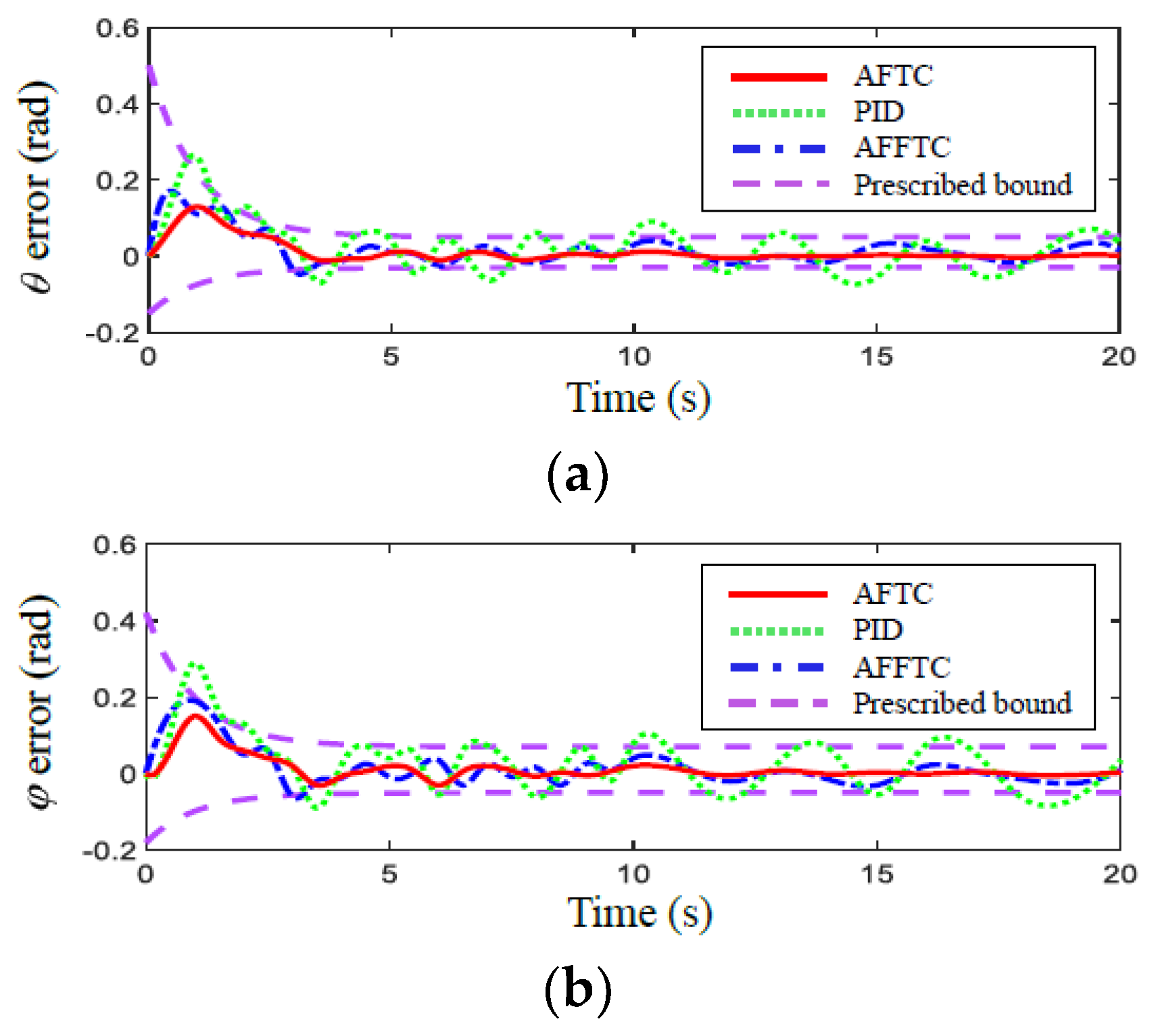
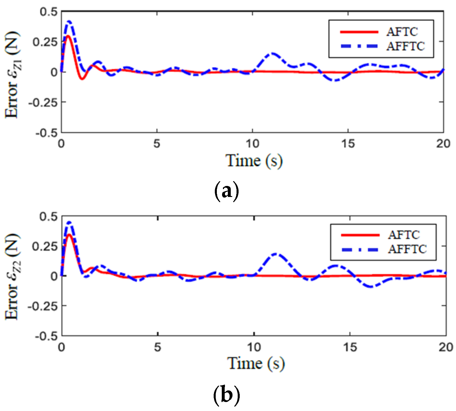
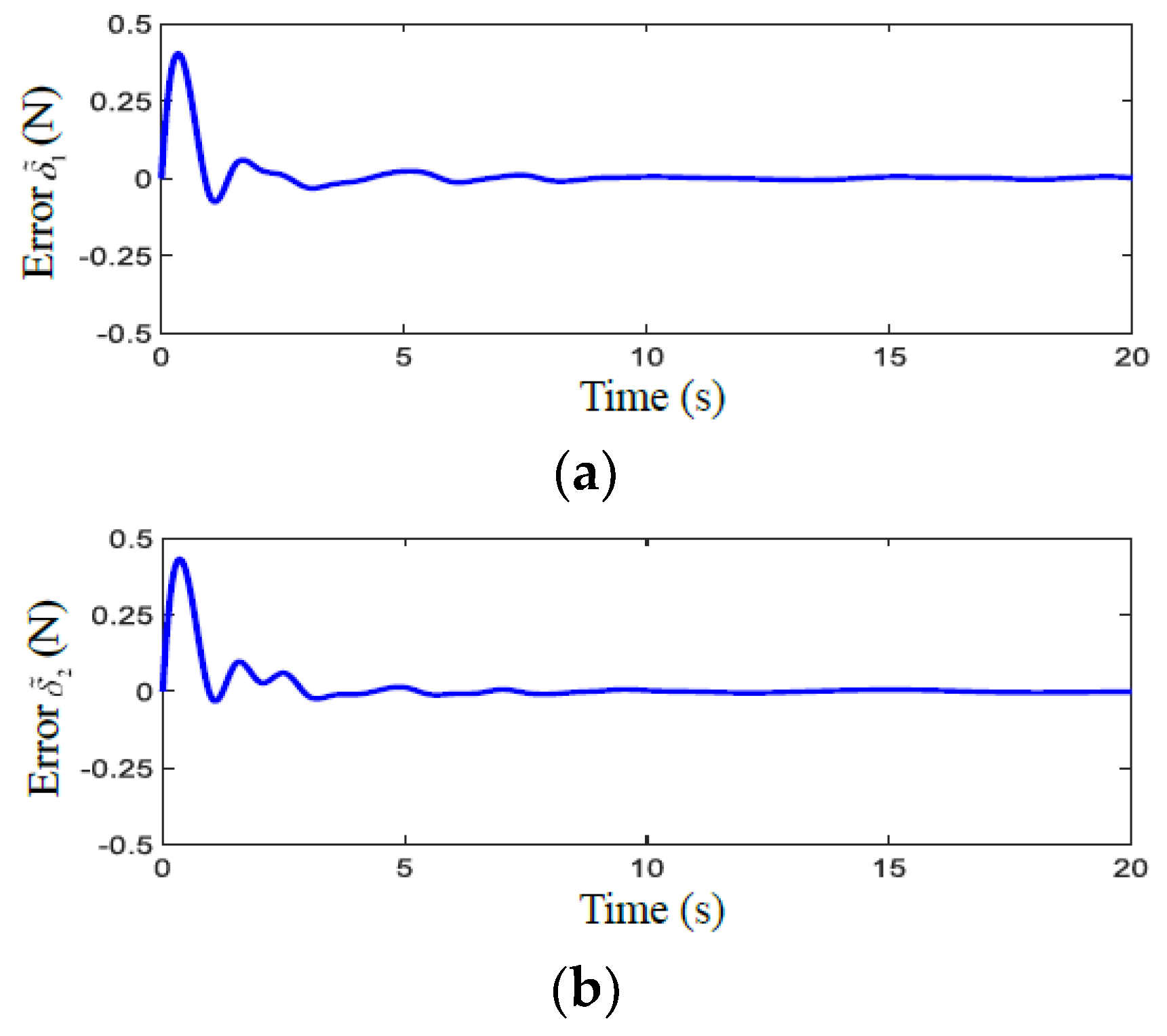
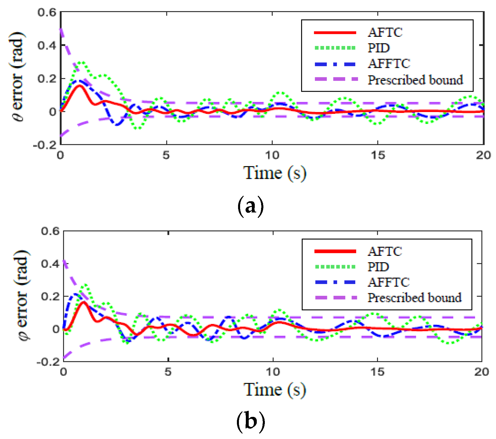
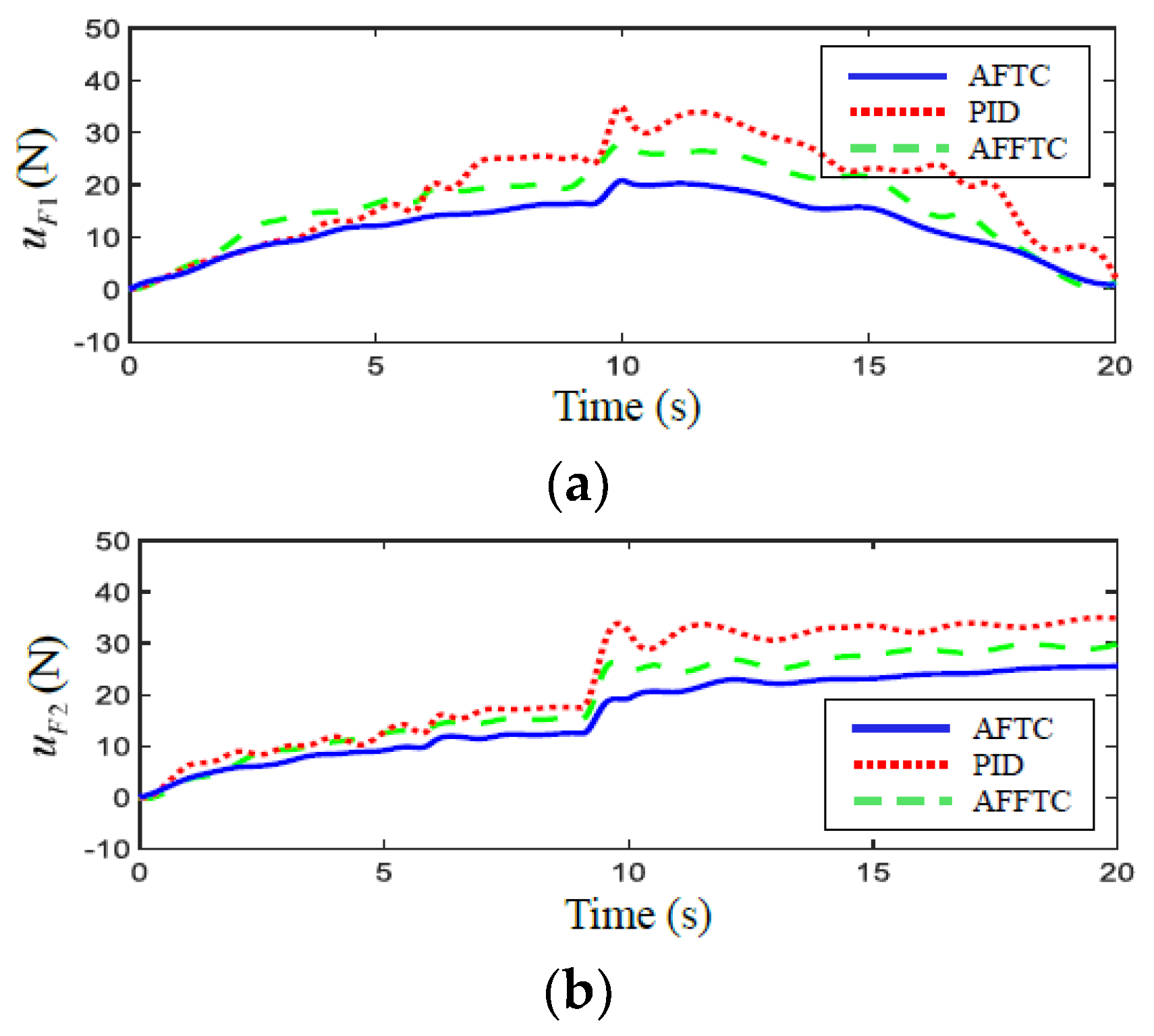
Figure 2 and Figure 3 show the simulation results of the trajectory tracking errors and driving forces of the continuum robot in the presence of the actuator faults and external disturbances, respectively. We can see that the three control methods that fulfill the trajectory tracking errors progressively converge to zero, and the proposed AFTC scheme attains a faster convergence rate than the PID and AFFTC methods. Evidently, when the actuator faults occur ( t = 10 s), the PID has inferior robustness to actuator faults, and the trajectory tracking errors cannot keep within the bound of time-varying constraints. For AFFTC, the trajectory tracking errors transcend the bound of time-varying constraints before 5 s. The proposed AFTC scheme offers much better robustness and transient response when the actuator faults occur ( t = 10 s), and assures that the trajectory tracking errors are always within the bound of time-varying constraints. Table 2 displays the tracking root-mean-square error (RMSE) of the three controllers. It is found that the proposed AFTC scheme manifests better trajectory tracking accuracy than the PID and AFFTC methods. Furthermore, Figure 4 and Figure 5 illustrate the approximation performance of the proposed AFTC scheme using FAT and DO. It can be seen that the proposed AFTC scheme utilizing FAT provides a better approximation performance than the AFFTC utilizing FLS, and the proposed DO has a good disturbance estimation ability. Thus, based on the simulation, it is concluded that the proposed AFTC scheme provides a better tracking performance than the PID and AFFTC methods of the continuum robot with actuator faults and external disturbances.

5. Experiment Results

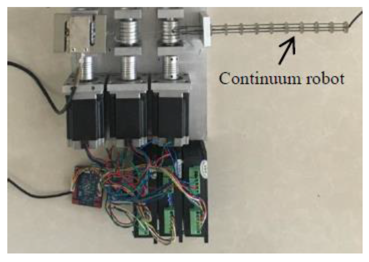
To illustrate the validity of the proposed AFTC scheme, the experimental validations for the proposed controller on a continuum robot are shown in Figure 6 [5]. The dimensions of the continuum robot are L = 210 mm and r = 5 mm. The desired trajectories, actuator faults, and FAT parameters are the same as the version in simulation. The controller parameters were chosen as a trade-off between the position tracking accuracy and chattering using trial and error. The parameters of PID are K p = diag [ 12 , 12 ] , K i = diag [ 6 , 6 ] , and K d = diag [ 15 , 15 ] . The parameters of the AFFTC are k c = 6 , λ b = 5 , c a = 5 , b 1 = 3 , b 2 = 0.8 , ϖ 1 = 0.1 , and ϖ 2 = 1.5 . The parameters of the AFFTC are K 1 = diag [ 7 , 7 ] , K 2 = diag [ 13 , 13 ] , χ s = 0.3 , γ 1 = 0.2 , γ 2 = 0.2 , Γ 1 = 3 , Γ 2 = 3 , and 1 = 0.2 .
The experiment results of the continuum robot are illustrated in Figure 7 and Figure 8, respectively. Moreover, Table 3 offers the trajectory tracking RMSE of three controllers. Clearly, the three controllers assure that the tracking errors converge to zero little by little. Compared with the PID and AFFTC methods, the proposed AFTC scheme carries faster transient convergence speed, a higher steady-state accuracy, and better robustness against the effects when the actuator faults occur ( t = 10 s). Furthermore, the proposed AFTC scheme always keeps the tracking errors within the bound of time-varying constraints. In contrast, the PID and AFFTC methods cannot ensure that the tracking errors remain within the bound of time-varying constraints all the time. Therefore, based on the above experiment outcomes and analysis, it can be concluded that the proposed AFTC scheme has a better tracking performance and robustness than the PID and AFFTC methods of the continuum robot.

6. Conclusions

In this paper, we proposed an AFTC scheme using the FAT and DO for the trajectory tracking of the continuum robot subjected to unknown actuator faults, uncertainties, unknown disturbances, and prescribed performance simultaneously. An adaptive control law combined with FAT is constructed to overcome the actuator faults and uncertainties of the continuum robot. Meanwhile, a novel nonlinear DO is applied to estimate and weaken the FAT approximation errors and unknown disturbances. Furthermore, a suitable asymmetric BLF is employed to avoid trajectory tracking errors for the continuum robot violating the bound of time-varying constraints. The stability of the proposed AFTC scheme is proved using the Lyapunov function. Then, the simulation results indicate that the proposed AFTC scheme can make the output track the target trajectory well, and ensure the prescribed performance compared with other advanced control methods. Finally, the experiment results show that the proposed controller gives a better tracking performance of the continuum robot. Future work will focus on developing an adaptive fault-tolerant tracking controller with input and joint constraints to deal with the faults of the sensor and actuator and the uncertainties of the continuum robot systems.

Funding

This research received no external funding.

Data Availability Statement

Data are contained within the article.

Conflicts of Interest

The authors declare no conflicts of interest.

Appendix A

Proof. 
Choosing Lyapunov function V 2 as
V 2 = V 1 + 1 2 e 2 T M 0 ( x 1 ) e 2 + 1 2 δ ˜ T δ ˜ + 1 2 i = 1 2 w ˜ i T Γ i 1 w ˜ i
Differentiating V 2 , one has
V ˙ 2 i = 1 2 λ i e 1 i e 2 i i = 1 2 μ 1 2 1 μ 1 2 k 1 i + e 2 T ( u F C 0 ( x 1 , x 2 ) x 2 G 0 ( x 1 ) δ W * T φ ( Z ) M 0 1 ( x 1 ) η ˙ 1 )
δ ˜ T δ ˙ + δ ˜ T Λ ( e 2 ) M 0 1 ( x 1 ) δ ˜ + δ ˜ T Λ ( e 2 ) M 0 1 ( x 1 ) W ˜ T φ ( Z ) i = 1 2 w ˜ i T φ i ( Z ) e 2 i i = 1 2 w ˜ i T γ i | e 2 i | w ^ i
After substituting (28) into (A2), this yields
V ˙ 2 i = 1 2 λ i e 1 i e 2 i i = 1 2 μ 1 2 1 μ 1 2 k 1 i + e 2 T ( W ˜ T φ ( Z ) λ e 1 K 2 e 2 C 0 ( x 1 , x 2 ) e 2 + δ ˜ ) δ ˜ T δ ˙
+ δ ˜ T Λ ( e 2 ) M 0 1 ( x 1 ) δ ˜ + δ ˜ T Λ ( e 2 ) M 0 1 ( x 1 ) W ˜ T φ ( Z ) i = 1 2 w ˜ i T φ i ( Z ) e 2 i i = 1 2 w ˜ i T γ i | e 2 i | w ^ i
i = 1 2 μ 1 2 1 μ 1 2 k 1 i e 2 T ( ( K 2 + C 0 ( x 1 , x 2 ) ) e 2 + e 2 T δ ˜ δ ˜ T δ ˙ + δ ˜ T Λ ( e 2 ) M 0 1 ( x 1 ) δ ˜
+ δ ˜ T Λ ( e 2 ) M 0 1 ( x 1 ) W ˜ T φ ( Z ) i = 1 2 w ˜ i T γ i | e 2 i | w ^ i
According to Young’s inequality, we obtain
e 2 T δ ˜ 1 2 e 2 T e 2 + 1 2 δ ˜ T δ ˜
δ ˜ T δ ˙ 1 2 δ ˜ T δ ˜ + 1 2 1 2
δ ˜ T Λ ( e 2 ) M 0 1 ( x 1 ) W ˜ T φ ( Z ) Λ ( e 2 ) M 0 1 ( x 1 ) 2 δ ˜ 2 2 ϑ 1 + ϑ 1 2 i = 1 2 W ˜ 2 φ i ( Z ) 2
i = 1 2 w ˜ i T γ i | e 2 i | w ^ i i = 1 2 γ i | e 2 i | 2 ( w ˜ i 2 w ^ i 2 ) 1 2 e 2 T e 2 + 1 8 i = 1 2 γ i ( w ˜ i 2 w ^ i 2 ) 2
where ϑ 1 is a positive constant. Substituting (A4)–(A7) into (A3), this yields
V ˙ 2 i = 1 2 μ 1 2 1 μ 1 2 k 1 i e 2 T ( ( K 2 + C 0 ( x 1 , x 2 ) I ) e 2 + 1 2 1 2
+ δ ˜ T [ Λ ( e 2 ) M 0 1 ( x 1 ) + 1 2 ϑ 1 ( Λ ( e 2 ) M 0 1 ( x 1 ) 2 + 2 ϑ 1 ) I ] δ ˜
1 4 i = 1 2 γ i 2 w ˜ i 2 w ^ i 2 + 1 8 i = 1 2 γ i 2 ( w ˜ i 4 + w ^ i 4 )
a 1 V 2 + b 1
where
a 1 = min { min i = 1 , 2 { 2 k 1 i } , 2 λ min ( K 2 + C 0 ( x 1 , x 2 ) I ) λ max ( M 0 ( x 1 ) ) ,
λ min ( 2 Λ ( e 2 ) M 0 1 ( x 1 ) + Λ ( e 2 ) M 0 1 ( x 1 ) 2 + 2 ϑ 1 ϑ 1 I ) , min i = 1 , 2 { γ i 2 w ^ i 2 2 λ max ( Γ i 1 ) } }
b 1 = 1 2 2 + 1 8 i = 1 2 γ i 2 ( w ˜ i 4 + w ^ i 4 )
To assure a 1 > 0 , the constant ϑ 1 , gain matrix K 2 , and matrix Λ ( e 1 ) are selected to satisfy
ϑ 1 > 0
λ min ( K 2 + C 0 ( x 1 , x 2 ) I ) > 0
λ min ( 2 Λ ( e 2 ) M 0 1 ( x 1 ) + Λ ( e 2 ) M 0 1 ( x 1 ) 2 + 2 ϑ 1 ϑ 1 I ) > 0
Multiplying both sides by e a 1 t in (A8), and integrating over [ 0 , t ] , one has
V 2 ( V 2 ( 0 ) b 1 a 1 ) e a 1 t + b 1 a 1
V 2 ( 0 ) + b 1 a 1
1 2 H 1
where H 1 = 2 ( V 2 ( 0 ) + b 1 / a 1 ) .
Then, in light of (A1), we have
1 2 ln 1 1 μ i 2 1 2 H 1
From (A15), yields
μ i 2 1 e H 1
Then, based on (16)–(18), yields
k b i 2 ( t ) ( 1 e H 1 ) e 1 i k c i 2 ( t ) ( 1 e H 1 )
In view of (A17), e 1 will converge to the bounded region [ k b i 2 ( t ) ( 1 e H 1 ) , k c i 2 ( t ) ( 1 e H 1 ) ] , and gradually converge to zero. Notice that H 1 and k b i ( t ) < 0 < k c i ( t ) ; then, e 1 i [ k b i ( t ) , k c i ( t ) ] can be easily derived. Thus, we can assure the tracking error e 1 within the prescribed bound. Furthermore, in the same way, it can be obtained that the inequalities hold the following:
e 2 < H 1 λ min ( M 0 ( x 1 ) )
w ˜ i < H 1 λ min ( Γ 1 )
δ ˜ < H 1
According to the (A17)–(A20) and uniformly bounded definition [33], it can be concluded that the errors e 1 , e 2 , w ˜ i , and δ ˜ are uniformly bounded. Therefore, all signals in the closed-loop system of the continuum robot are uniformly bounded. □

References

  1. Gao, Y.; Takagi, K.; Kato, T.; Shono, N.; Hata, N. Continuum robot with follow-the-leader motion for endoscopic third ventriculostomy and tumor biopsy. IEEE Trans. Biomed. Eng. 2020, 67, 379–390. [Google Scholar] [CrossRef] [PubMed]
  2. Xiao, B.; Cao, L.; Xu, S.; Liu, L. Robust tracking control of robot manipulators with actuator faults and joint velocity measurement uncertainty. IEEE/ASME Trans. Mechatron. 2020, 25, 1354–1365. [Google Scholar] [CrossRef]
  3. He, B.; Wang, Z.; Li, Q.; Xie, H.; Shen, R. An analytic method for the kinematics and dynamics of a multiple-backbone continuum robot. Int. J. Adv. Robot. Syst. 2013, 10, 84. [Google Scholar] [CrossRef]
  4. Jabari, M.; Zakeri, M.; Janabi-Sharifi, F.; Norouzi-Ghazbi, S. Inverse kinematics of concentric tube robots in the presence of environmental constraints. Appl. Bionics Biomech. 2021, 2021, 4107732. [Google Scholar] [CrossRef] [PubMed]
  5. Xu, S.; He, B. Adaptive approximation tracking control of a continuum robot with uncertainty disturbances. IEEE Trans. Cybern. 2024, 54, 230–240. [Google Scholar] [CrossRef] [PubMed]
  6. Lai, J.; Huang, K.; Lu, B.; Zhao, Q.; Chu, H. Verticalized-tip trajectory tracking of a 3D-printable soft continuum robot: Enabling surgical blood suction automation. IEEE/ASME Trans. Mechatron. 2022, 27, 1545–1556. [Google Scholar] [CrossRef]
  7. Xu, S. Adaptive approximation sliding-mode control of an uncertain continuum robot with input nonlinearities and disturbances. Appl. Bionics Biomech. 2024, 2024, 8533606. [Google Scholar] [CrossRef]
  8. Jin, X.; Che, W.; Wu, Z.; Wang, H. Analog control circuit designs for a class of continuous-time adaptive fault-tolerant control systems. IEEE Trans. Cybern. 2022, 52, 4209–4220. [Google Scholar] [CrossRef]
  9. Zhu, S.; Li, H.; Wang, G.; Kuang, C.; Chen, H.; Gao, J.; Xie, W. Research on fault-tolerant control of distributed-drive electric vehicles based on fuzzy fault diagnosis. Actuators 2023, 12, 246. [Google Scholar] [CrossRef]
  10. Chang, Y.; Wu, C.; Lin, H. Adaptive distributed fault-tolerant formation control for multi-robot systems under partial loss of actuator effectiveness. Int. J. Control Autom. Syst. 2018, 16, 2114–2124. [Google Scholar] [CrossRef]
  11. Lomakin, A.; Deutscher, J. Reliable algebraic fault detection and identification of robots. IEEE Trans. Autom. Sci. Eng. 2022, 19, 3821–3837. [Google Scholar] [CrossRef]
  12. Zhao, D.; Jiang, B.; Yang, H. Backstepping-based decentralized fault-tolerant control of hypersonic vehicles in PDE-ODE form. Int. J. Robust Nonlinear Control 2022, 67, 1210–1225. [Google Scholar] [CrossRef]
  13. Van, M.; Mavrovouniotis, M.; Ge, S.S. An adaptive backstepping nonsingular fast terminal sliding mode control for robust fault tolerant control of robot manipulators. IEEE Trans. Syst. Man Cybern. Syst. 2019, 49, 1448–1458. [Google Scholar] [CrossRef]
  14. Zhang, J.; Yang, G. Adaptive fuzzy fault-tolerant control of uncertain Euler-Lagrange systems with process faults. IEEE Trans. Fuzz. Syst. 2020, 28, 2619–2630. [Google Scholar] [CrossRef]
  15. Chen, Z.; Wang, X.; Cheng, Y. Model free based finite time fault-tolerant control of robot manipulators subject to disturbances and input saturation. Int. J. Robust Nonlinear Control 2022, 32, 5281–5303. [Google Scholar] [CrossRef]
  16. Van, M.; Ge, S.S. Adaptive fuzzy integral sliding-mode control for robust fault-tolerant control of robot manipulators with disturbance observer. IEEE Trans. Fuzz. Syst. 2021, 29, 1284–1296. [Google Scholar] [CrossRef]
  17. He, W.; Huang, H.; Ge, S.S. Adaptive neural network control of a robotic manipulator with time-varying output constraints. IEEE Trans. Cybern. 2017, 47, 3136–3147. [Google Scholar] [CrossRef] [PubMed]
  18. Hu, B.; Guan, Z.; Lewis, F.; Chen, C.L.P. Adaptive tracking control of cooperative robot manipulators with markovian switched couplings. IEEE Trans. Ind. Electron. 2021, 68, 2427–2436. [Google Scholar] [CrossRef]
  19. Lin, C.; Sie, T. Design and experimental characterization of artificial neural network controller for a lower limb robotic exoskeleton. Actuators 2023, 12, 55. [Google Scholar] [CrossRef]
  20. Liu, Y.; Zhang, H.; Wang, Y.; Sun, S. Adaptive fuzzy control for nonstrict-feedback systems under asymmetric time-varying full state constraints without feasibility condition. IEEE Trans. Fuzz. Syst. 2021, 29, 976–985. [Google Scholar] [CrossRef]
  21. Lv, M.; Li, Y.; Pan, W.; Baldi, S. Finite-time fuzzy adaptive constrained tracking control for hypersonic flight vehicles with singularity-free switching. IEEE/ASME Trans. Mechatron. 2022, 27, 1594–1605. [Google Scholar] [CrossRef]
  22. Wang, S.; Yu, H.; Yu, J.; Na, J.; Ren, X. Neural-network-based adaptive funnel control for servo mechanisms with unknown dead-zone. IEEE Trans. Cybern. 2021, 50, 1383–1394. [Google Scholar] [CrossRef]
  23. Zhang, Y.; Niu, H.; Tao, J.; Li, X. Novel data and neural network-based nonlinear adaptive switching control method. IEEE Trans. Neural Netw. Learn. Syst. 2022, 33, 789–797. [Google Scholar] [CrossRef]
  24. Huang, H.; Pan, H.; Cheng, Y. Tracking control for flexible joint robots based on adaptive fuzzy compensation with uncertain parameters. Int. J. Adapt. Control Signal Process. 2021, 35, 1633–1648. [Google Scholar] [CrossRef]
  25. Izadbakhsh, A. FAT-based robust adaptive control of electrically driven robots without velocity measurements. Nonlinear Dyn. 2017, 89, 289–304. [Google Scholar] [CrossRef]
  26. Wang, Y.; Bai, Y.; Svinin, M. Function approximation technique based adaptive control for chaos synchronization between different systems with unknown dynamics. Int. J. Control Autom. Syst. 2021, 19, 2611–2621. [Google Scholar] [CrossRef]
  27. Khodamipour, G.; Khorashadizadeh, S.; Farshad, M. Observer-based adaptive control of robot manipulators using reinforcement learning and the Fourier series expansion. Trans. Inst. Meas. Control 2021, 43, 2307–2320. [Google Scholar] [CrossRef]
  28. Bu, W.; Li, T.; Yang, J.; Yi, Y. Disturbance observer-based event-triggered tracking control of networked robot manipulator. Meas. Control 2020, 53, 892–898. [Google Scholar] [CrossRef]
  29. Zhang, J.; Zhao, W.; Shen, G.; Xia, Y. Disturbance observer-based adaptive finite-time attitude tracking control for rigid spacecraft. IEEE Trans. Syst. Man Cybern. Syst. 2021, 51, 6606–6613. [Google Scholar] [CrossRef]
  30. Mao, Q.; Dou, L.; Yang, Z.; Tian, B.; Zong, Q. Fuzzy disturbance observer-based adaptive sliding mode control for reusable launch vehicles with aeroservoelastic characteristic. IEEE Trans. Ind. Inform. 2020, 16, 1214–1223. [Google Scholar] [CrossRef]
  31. Zhang, Q.; He, D. Disturbance-observer-based adaptive fuzzy control for strict-feedback switched nonlinear systems with input delay. IEEE Trans. Fuzz. Syst. 2021, 29, 1942–1952. [Google Scholar] [CrossRef]
  32. Li, Z.; Su, C.; Wang, L.; Chen, Z.; Chai, T. Nonlinear disturbance observer-based control design for a robotic exoskeleton incorporating fuzzy approximation. IEEE Trans. Ind. Electron. 2015, 62, 5763–5775. [Google Scholar] [CrossRef]
  33. Zhao, Z.; He, X.; Ahn, C. Boundary disturbance observer-based control of a vibrating single-link flexible manipulator. IEEE Trans. Syst. Man. Cybern. Syst. 2021, 51, 2382–2390. [Google Scholar] [CrossRef]
  34. Cui, G.; Yu, J.; Shi, P. Observer-based finite-time adaptive fuzzy control with prescribed performance for nonstrict-feedback nonlinear systems. IEEE Trans. Fuzz. Syst. 2022, 30, 767–778. [Google Scholar] [CrossRef]
  35. Zhou, Q.; Zhao, S.; Li, H.; Lu, R.; Wu, C. Adaptive neural network tracking control for robotic manipulators with dead zone. IEEE Trans. Neural Netw. Learn. Syst. 2019, 30, 3611–3620. [Google Scholar] [CrossRef] [PubMed]
  36. Shao, X.; Hu, Q.; Shi, Y.; Jiang, B. Fault-tolerant prescribed performance attitude tracking control for spacecraft under input saturation. IEEE Trans. Control Syst. Technol. 2020, 28, 574–582. [Google Scholar] [CrossRef]
  37. Nai, Y.; Yang, Q.; Wu, Z. Prescribed performance adaptive neural compensation control for intermittent actuator faults by state and output feedback. IEEE Trans. Neural Netw. Learn. Syst. 2021, 32, 4931–4945. [Google Scholar] [CrossRef]
  38. Shen, Z.; Wang, Q.; Dong, S.; Yu, H. Dynamic surface control for tracking of unmanned surface vessel with prescribed performance and asymmetric time-varying full state constraints. Ocean. Eng. 2022, 253, 111319. [Google Scholar] [CrossRef]
  39. Liu, Y.; Gong, M.; Liu, L.; Tong, S.; Chen, C.L.P. Fuzzy observer constraint based on adaptive control for uncertain nonlinear MIMO systems with time-varying state constraints. IEEE Trans. Cybern. 2021, 51, 1380–1389. [Google Scholar] [CrossRef]
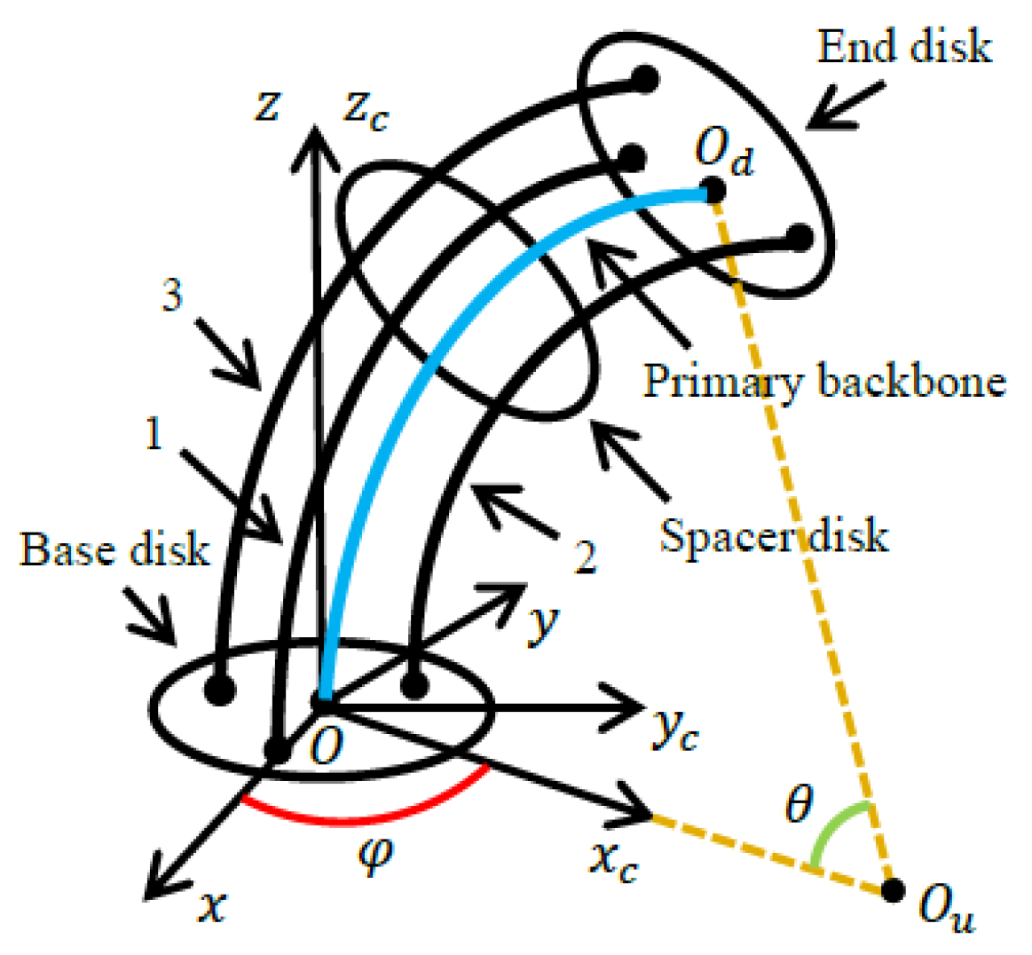
Figure 1. The bending model of the continuum robot.
Actuators 13 00267 g001
Figure 2. Simulation of the tracking errors for the continuum robot. (a) Tracking errors of θ . (b) Tracking errors of φ .
Actuators 13 00267 g002
Figure 3. Simulation of the driving forces for the continuum robot. (a) Driving force u F 1 . (b) Driving force u F 2 .
Actuators 13 00267 g003
Figure 4. Error ε Z = [ ε Z 1 , ε Z 2 ] T of AFTC and AFFTC for the continuum robot. (a) Error ε Z 1 . (b) Error ε Z 2 .
Actuators 13 00267 g004
Figure 5. Disturbance error δ ˜ = [ δ ˜ 1 , δ ˜ 2 ] T of AFTC scheme for the continuum robot. (a) Error δ ˜ 1 . (b) Error δ ˜ 2 .
Actuators 13 00267 g005
Figure 6. The prototype of the continuum robot.
Actuators 13 00267 g006
Figure 7. The prototype of the continuum robot. Experiment of the tracking errors for the continuum robot. (a) Tracking errors of angle θ . (b) Tracking errors of angle φ .
Actuators 13 00267 g007
Figure 8. Experiment of the driving forces for the continuum robot. (a) Driving force u F 1 . (b) Driving force u F 2 .
Actuators 13 00267 g008
Table 1. Parameters of the controllers in simulation.
ControllersParameters
PID K p = diag [ 10 , 10 ] , K i = diag [ 8 , 8 ] , K d = diag [ 20 , 20 ]
AFFTC k c = 8 , λ b = 6 , c a = 3 , b 1 = 2 ,
b 2 = 0.6 , ϖ 1 = 0.2 , ϖ 2 = 1
AFTC K 1 = diag [ 5 , 5 ] , K 2 = diag [ 10 , 10 ] , χ s = 0.5 ,
γ 1 = 0.1 , γ 2 = 0.1 , Γ 1 = 2 , Γ 2 = 2 , 1 = 0.3
Table 2. Tracking errors of the controllers in simulation.
Controllers θ RMSE (rad) φ RMSE (rad)
PID0.02160.0273
AFFTC0.01830.0172
AFTC0.01020.0118
Table 3. Tracking error of the controllers in experiments.
Controllers θ RMSE (rad) φ RMSE (rad)
PID0.02370.0295
AFFTC0.01960.0183
AFTC0.01120.0126
Disclaimer/Publisher’s Note: The statements, opinions and data contained in all publications are solely those of the individual author(s) and contributor(s) and not of MDPI and/or the editor(s). MDPI and/or the editor(s) disclaim responsibility for any injury to people or property resulting from any ideas, methods, instructions or products referred to in the content.