Abstract
Soft continuum robots, characterized by their dexterous and compliant nature, often face limitations due to buckling under small loads. This study explores the enhancement of axial performance in soft robots intrinsically actuated with extensile fluidic artificial muscles (EFAMs) through the incorporation of bio-inspired radial supports, or ossicles. By conducting quasi-static force response experiments under varying pressure conditions (103.4–517.1 kPa), and a modified Euler column buckling model, we demonstrate that ossicles significantly increase the robots’ resistance to buckling, thereby extending their application scope in payload-carrying tasks. These findings not only underscore the effectiveness of ossicle reinforcement in improving structural robustness but also pave the way for future research to optimize soft robot design for enhanced performance.
1. Introduction
Recent advancements in robotics and material science have catalyzed the emergence of soft robots, capable of operation outside the confines of structured environments such as labs and factories [1]. These robots, crafted from materials with a Young’s modulus below Pa [2], are designed to emulate the adaptability and safety of biological counterparts, promising applications in diverse areas from autonomous exploration to minimally invasive surgery. However, their inherent softness, while advantageous for compliance and safety, often results in a significant drawback: a tendency to buckle under modest loads, limiting their functional utility in tasks demanding substantial actuation forces.
Continuum soft robots, which blend the attributes of soft robotics with the versatility of hyper-redundant systems [3], typically employ extensile fluidic artificial muscles (EFAMs) to achieve a broad range of motion. These EFAM-driven systems, exemplified in various configurations and applications [4,5,6,7], demonstrate the potential for significant functional versatility. These EFAM-driven robots leverage multiple interconnected EFAMs to achieve complex, continuous bending motions, adjusting to new equilibrium states upon actuation (see Figure 1). This study explores the potential of enhancing the structural integrity and actuation capacity of EFAM-actuated continuum soft robots through bio-inspired skeletal reinforcements.
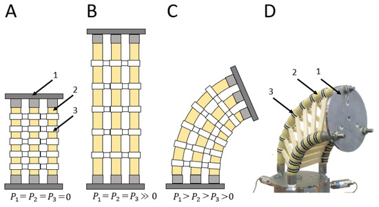
Figure 1.
(A–D) Diagram of a continuum soft robot constructed from end plates (1); extensile fluidic artificial muscles (2); and radial supports (ossicles) (3): (A) deflated; (B) equally pressurized; (C) differentially pressurized; (D) differentially pressurized (prototype).
The early development of continuum robots utilizing fluidic artificial muscles (FAMs) was marked by the creation of a manipulator capable of rotating substantial loads using a combination of contractile and extensile muscles [8]. This innovation paved the way for the OctArms series and other EFAM-driven continuum manipulators, which were validated through extensive research [5,9,10,11]. Further advancements saw the use of EFAMs in modulating the stiffness of continuum robots, offering a means to adjust their rigidity independently of muscle contraction [12]. Explorations into single-EFAM applications demonstrated their potential to produce complex motions such as bending and twisting thereby contributing to the versatility of continuum soft robots [13]. However, the inherent flexibility that grants these robots their unique capabilities also introduces a critical challenge: their tendency to buckle under minor loads. This mechanical limitation hampers the effective force transmission and, by extension, the payload capacity, of such systems, which highlights the need for improved understanding of, and innovation in, soft robotic design.
To increase the payload capability of continuum soft robots, we drew inspiration from brittle stars, specifically their ossicle-reinforced appendages that are known for their flexibility and strength [14]. This biomimicry informs the development of robots with similar kinematic properties, integrating skeletal elements to bolster performance without compromising flexibility. Our approach builds upon an EFAM-driven manipulator, incorporating radial ossicle-like supports to fortify the structure without stiffening it, thus maintaining the inherent advantages of soft robotics (see Figure 1A–D).
This concept of ossicle-inspired reinforcement was empirically validated in [15], where a multi-segment arm with radial supports demonstrated a significantly expanded operational range. Unlike previous models that used an exoskeleton with fixed-length section, our design employs a series of disconnected ossicles, accommodating the expansive stroke of EFAMs and enhancing robot adaptability.
Parallel research by [16,17] on CFAM-driven systems with radial supports underscored the benefits of such reinforcements in increasing lateral stiffness and resistance to buckling. Other researchers adopted a similar approach, using constraining plates to enhance torsional stiffness and reduce shape deviations, also addressing lateral buckling issues [18,19]. Although these studies did not directly draw from brittle star ossicles, their underlying principles resonate with our approach, suggesting a broader applicability of ossicle-like structures in soft robotics, including alternative actuator types like hydro muscles and rPAMs [20,21].
Complementary investigations into the buckling behaviors of contractile muscles by [22,23] further contextualize our study within the broader discourse on enhancing soft robot resilience and performance through strategic reinforcement.
While previous studies have successfully employed constraining plates to improve torsional stiffness and mitigate shape deviations in soft robots, there remains a notable gap in exploring the integration of bio-inspired ossicle reinforcements for enhancing load-bearing capacity and structural resilience without compromising the inherent flexibility of EFAM-driven continuum soft robots. This study aims to fill this gap by investigating the effectiveness of ossicle-like supports in extending the functional capabilities and the application range of these robots.
Despite ossicle reinforcement being recognized for its potential to vary lateral and torsional stiffness, enhance buckling capacity, and maintain structural integrity in soft robots, much of this knowledge remains unquantified in engineering practice. This gap underscores the need for a systematic investigation into the quantitative impacts of ossicle integration on the payload capacity, structural stiffness, and the actuation efficiency of EFAM-driven continuum soft robots. Our study is dedicated to bridging this gap by providing empirical evidence and a deeper understanding of how ossicle reinforcements can optimize soft robotic performance. How do ossicle reinforcements quantitatively affect the payload capacity, structural stiffness, and actuation efficiency of EFAM-driven continuum soft robots?
Our study examined the effect of ossicle reinforcement on the axial behavior of EFAM-driven soft robots through experiments that yielded force–displacement curves across a pressure range of – kPa, identifying buckling conditions. These data informed a model correlating ossicle quantity with buckling resistance, providing insights into the reinforcement’s impact on robot performance. The study provides a foundation for designing more robust and adaptable ossicle-reinforced soft robots, broadening their applicability in payload-carrying applications.
Initial Observations
The study was also motivated with initial observations in pictographic data that we found worth sharing. We collected for an EFAM continuum soft robot in bending. Figure 2 presents four robot configurations, each reinforced with an increasing number of ossicles and subjected to progressively higher payloads.
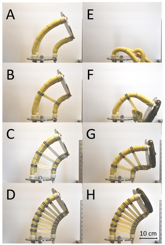
Figure 2.
Radial supports (i.e., ossicles) enhance the payload capacity of a continuum soft robot. (A–D) Robot carrying an aluminum end plate ( g) with varying ossicle reinforcements (0, 1, 3, and 7, respectively). (E–H) The robot, reinforced with ossicles, bearing a heavier payload ( g). The two left muscles were pressurized at 80 psi (552 kPa), and the right muscle at 5 psi (34 kPa).
In these tests, a robot configured with three EFAMs and varying numbers of ossicles demonstrated significant variations in the bending and payload capacity. Each EFAM, with a resting length of cm and an outer diameter of cm, was positioned cm from the center, contributing to a base weight of 129 g for the robot’s main structure. Additional weight came from the 3D-printed ABS ossicles, each adding g. Two muscles on the left were pressurized to kPa (80 psi) and the muscle on the right was pressurized to kPa (5 psi).
Initial observations revealed that, without ossicles, the robot could support an aluminum end plate with a mass of g; however, the robot exhibited a near-collapse curvature even under this minimal load. Conversely, with seven ossicles, the robot maintained a more uniform curvature and resisted buckling, even under a significantly higher payload of g, a more than seven-fold increase compared to its own mass. These findings, detailed further with various pressure and payload configurations in the Appendix (Figure A1, Figure A2, Figure A3 and Figure A4), underscored the ossicles’ critical role in increasing the robot’s load-bearing capabilities, prompting a deeper examination of their effect in axial scenarios.
2. Materials and Methods
The length and stiffness of an EFAM vary with applied internal pressure, influencing its movement and bending capabilities. While the standard operation primarily involves bending, the robot’s axial response was examined under uniform muscle pressurization levels. This axial testing aimed to offer insights into behaviors targeted for more complex bending scenarios in future studies. Analysis of the axial force response yielded crucial parameters such as blocked forces, free extensions, dead-band pressures, and structural stiffness, utilizing methods adapted from prior research on fluidic artificial muscles (FAMs) [24]. Additionally, the impact of the number of ossicles on axial performance was investigated through repeated experiments with varying ossicle counts. This evaluation involved testing five configurations, progressively reducing the number of ossicles down to three to avoid low buckling limits. The axial performance assessment utilized a quasi-static force–response testing procedure conducted with a Material Testing System (MTS), following methodologies established in contractile-FAM force response testing [24]. Buckling was observed in each experiment except for the 7-ossicle continuum soft robot configuration.
2.1. Materials
The continuum robot segment was assembled from three EFAMs and two rigid end plates. The three EFAMs were manufactured in-house: resting length and diameter of cm and cm; resting braid angle of (measured from the muscle lateral cross-section). The end fittings were manufactured with a swaging process described in [25]. EFAM performance was quantified with a blocked force of 280 N and stroke at maximum testing internal pressure of 75 psi. The design and manufacturing processes of EFAMs closely resembled those of contractile FAMs (CFAMs) [25], and were further described in [26]. More data on the EFAM design, materials, and their pre-assembly dimensions can be found in Figure 3B and Table 1.
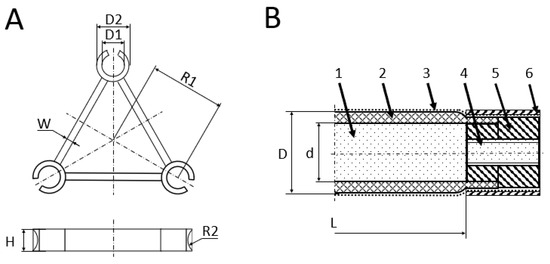
Figure 3.
(A) Dimensions of an ossicle. (B) Cross-section diagram of an extensile fluidic artificial muscle: fluid medium (1), elastomeric tube (2), bi-axial inextensible sleeve (3), fluid inlet (4), end fitting (5), swage tube (6).

Table 1.
Components of the extensile FAM assembly with their corresponding dimensions.
For the test setup, the EFAMs were equilaterally mounted to two mm thick aluminum plates, as shown in Figure 4. The ossicles were manufactured using uPrint® 3D-printer and ABS-M30 thermoplastic of Stratasys (Eden Prairie, MN, USA). The ossicles were equally spaced along the EFAMs and fastened with cable ties to reinforce their grip on the EFAMs. Figure 3A shows the dimensions of a single ossicle. The end plates and ossicles placed EFAMs cm away from the robot axis. An ossicle measured mm in height and mm in bar thickness. The EFAM-clamp part of the ossicle measured mm and mm with mm.
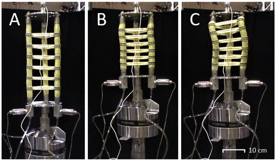
Figure 4.
The robotic segment, reinforced with six ossicles, underwent testing at 517 kPa, as shown in sequential stages: nominal operation (A), imminent buckling (B), and the buckled state (C). A slight displacement from stage B induced the critical buckling force, rapidly transitioning to the buckled condition in (C). Due to potential damage risks, the test was discontinued upon reaching the buckled state.
For quasi-static axial force response testing, a 97.9 kN MTS servo-hydraulic test machine (or MTS machine) was used to achieve the desired stroke profiles, and to acquire displacement and force data. The MTS Teststar Controller (Eden Prairie, MN, USA) measured time, displacement, and force. An external load cell (Honeywell Model 31-CV) rated for 1000 lbf (4448 N) provided high-resolution force readings. Pressure values for each FAM were obtained with three 200 psi-rated pressure transducers (Omega PC209-200G5V (Norwalk, CT, USA)). The values were recorded by a pressure regulation system adapted from [26] and regulated the internal pressure of the three EFAMs (Figure 5).
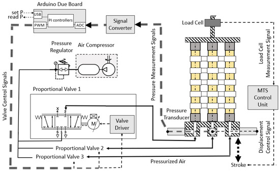
Figure 5.
Schematic of the test setup. Dashed lines represent electric signals, while solid lines denote pneumatic connections. Key components include the Arduino Due Board for control signals, an air compressor and pressure regulator for air supply, proportional valves and pressure transducers for closed-loop pressure control, a load cell for measuring applied force, and an MTS control unit for displacement measurement.
2.2. Methods
The objective of the experiments was to evaluate the impact of ossicle reinforcement on the axial performance and buckling behavior of the continuum soft robot. The experimental setup included the configuration of the robot with EFAMs placed equidistant from the center, reinforced with varying numbers of ossicles.
With the setup shown in Figure 5, the robot was stroked at mm/s starting from its free extension, as indicated by the load cell’s reading of 0 N, and stopping at the resting length of the robot, as directed by the MTS displacement control system. At each test pressure, the robot was stroked for 3 up-and-down cycles. The robot was tested under five pressure levels ranging from to kPa (15–75 psi) in kPa (15 psi) increments. For brevity, further references to the tested pressure were rounded to natural numbers. Buckling observations were also performed by incrementally increasing the pressure and observing the robot for signs of buckling, halting the tests at the first indication of buckling to prevent damage. Force response data were acquired for the robot, incrementally reducing the number of ossicles from 7 to 3, as shown in Figure 6.
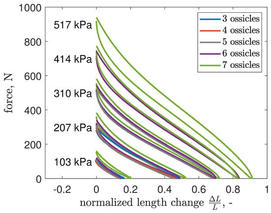
Figure 6.
Axial force response of an EFAM-actuated soft robot to varying displacement at different pressure levels, and with incrementally changing number ossicles.
Data on force, displacement, and internal pressure were collected using the 0MTS machine (Eden Prairie, MN, USA), load cell, and pressure transducers. Data were logged using the MTS control system software and subsequently analyzed using MATLAB® (2022a). The analyses followed methodologies established in our prior CFAM force response testing [24,27,28]. Theses analyses included extracting blocked force and free extension for each tested pressure from the force–displacement data, and fitting a linear function to the blocked force data to determine the dead-band pressure. Moreover, we further analyzed the experimental results with a modified Euler column model to be described in Section 4.
3. Experimental Results
The continuum soft robot, operating axially, functions similarly to a soft actuator through its composition of three EFAMs (see Figure 7). Methods originally developed for FAMs proved applicable for analyzing the axial-force–response data of the soft robot. Analysis included trends in force response, examining parameters such as maximum non-buckling pressure, dead-band pressure, blocked force, and free extension to understand the influence of radial supports on robot performance.
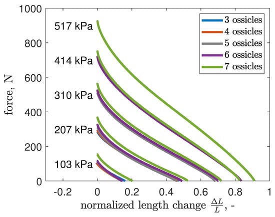
Figure 7.
Averaged axial force response of an EFAM-actuated soft robot, fabricated at the University of Maryland, to varying displacement normalized by the robot’s resting length at different pressure levels, and with incrementally changing number of ossicles.
3.1. Maximum Non-Buckling Pressure
Under specific pressures and displacements, the robot experienced buckling, akin to a hyper-elastic column under compression, as depicted in Figure 4. This buckling, which posed a risk of damage to both the robot and the test setup, was triggered when the robot reached its critical force limit during a gradual compression test at constant internal pressure. To mitigate this, the test was halted at the first sign of buckling, with the last safe pressure level recorded as the maximum sustainable without buckling. Notably, the incorporation of ossicles was effective in curbing this issue; only the variant with seven ossicles managed to resist buckling at the peak internal pressure of 517 kPa. This is reflected in Figure 7, where the absence of data points for certain ossicle counts indicates buckling incidents. The data show that, up to 207 kPa, buckling was prevented in all configurations. Beyond this, only configurations with five, six, and seven ossicles withstood up to 310 kPa, six and seven ossicles up to 414 kPa, and only the seven ossicle configuration remained stable up to 517 kPa.
3.2. Dead-Band Pressure
Another performance metric, dead-band pressure, can be calculated to observe whether the number of ossicles affected a pressure threshold needed for the robot to generate force. Dead-band pressure, , is the pressure required for the bladder to make substantial contact with the surrounding braid and initiate inflation of the FAM [29]. A linear fit to the experimental data for blocked force would yield a pressure value greater than zero for the blocked force of zero—a pressure level above which FAMs start to generate force. This is a pressure difference between the pressure-proportional Gaylord’s FAM model:
where is the blocked force, P is the internal pressure, D is the outer diameter, is the resting braid angle. The experimental data are the estimated value of the dead-band pressure. The dead-band pressure trend is shown in Figure 8. The data for the dead-band pressure were monotonically decreasing, and it suggests that the ossicles might decrease dead-band pressure.
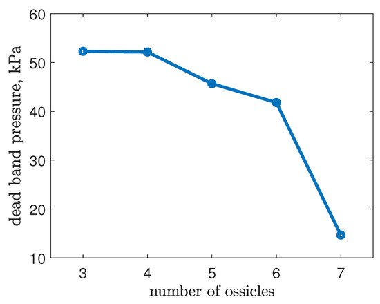
Figure 8.
Dead-band pressure calculated from experimental data versus the number of ossicles. With increasing number of ossicles, the dead-band pressure decreases.
3.3. Blocked Force
Blocked force data were analyzed to determine the impact of ossicle quantity on the robot’s axial force output at its resting length, providing insights into maximum force capabilities with minimal material strain influence.
As depicted in Figure 9, initial findings indicate a marginal increase in blocked forces at lower pressures (103 and 207 kPa), potentially due to ossicles promoting earlier bladder-braid contact, thereby reducing the dead-band pressure. Notably, the inclusion of ossicles enabled the robot to sustain operation at elevated pressures, which was challenging with fewer ossicles. Specifically, the peak force observed in the robot with seven ossicles surpassed that of the three-ossicle variant by over three-fold, attributable to the expanded non-buckling pressure range from 207 kPa to 517 kPa.
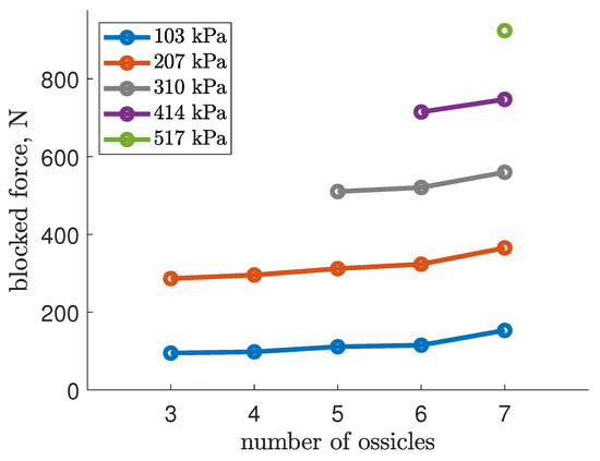
Figure 9.
Blocked forces generated by an EFAM-actuated soft robot dependent on the number of radial supports (or ossicles).
3.4. Free Extension
Free extension, defined as the maximum normalized length change of a pneumatic soft actuator under specific internal pressure without external forces, is a key performance metric. This metric is calculated by dividing the actuator’s length change by its resting length. Figure 10 illustrates how the number of ossicles correlates with free extension, indicating a minor but present influence, which was deemed negligible for this study.
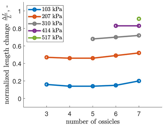
Figure 10.
Free extension of an EFAM-actuated soft robot.
Notably, ossicle reinforcement enabled operation at higher pressures, resulting in a significant increase in free extension, with the seven-ossicle configuration achieving twice the extension of the three-ossicle setup.
3.5. Axial Stiffness
Axial stiffness, defined as the force needed for a unit length change in the robot, varies with pressure and was analyzed under the assumption of constant stiffness across different lengths. This stiffness was derived from data presented in Figure 7, reinterpreted to consider the robot as a compressed column, with results illustrated in Figure 11. Here, force versus compression data are displayed, with each ossicle count’s trendline shifted by 300 N for differentiation. Solid lines indicate experimental data, while dotted lines offer linear approximations of axial stiffness at specific pressures and ossicle counts, summarized in Figure 12.
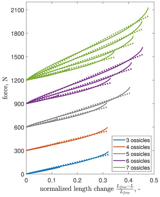
Figure 11.
Quasi-static force response with the robot as a uniformly cross-sectioned column under compression. Data for each ossicle increment are offset by 300 N for clarity, with solid lines showing experimental results and dotted lines indicating linear approximations.
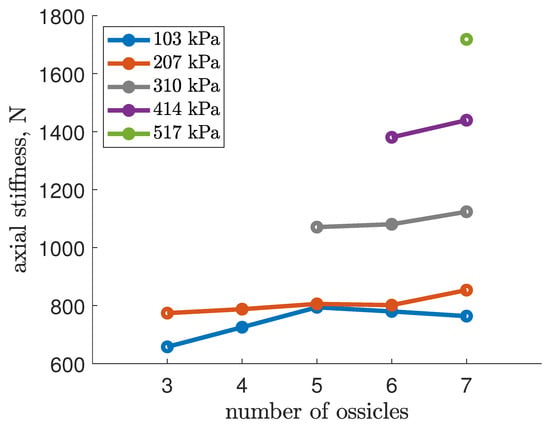
Figure 12.
Axial stiffness, , of an EFAM-actuated soft robot as a function of the number of ossicles at 5 testing internal pressures.
At 103 kPa, no clear trend emerged, possibly due to EFAMs not yet reaching nominal behavior just above dead-band pressures, indicating strong nonlinearity. At higher pressures, stiffness trends were consistent, with a peak increase of % at 207 kPa and under 5% for 310 and 414 kPa. These findings suggest that while the ossicle count influences axial stiffness, the inherent soft axial characteristics of the robot remain largely intact.
4. Buckling Analysis
To address the limitations in quantifying the buckling performance from the last section, we applied an Euler column model with an ossicle-dependent coefficient to analyze the buckling behavior of the robot. This approach enables the calculation of the critical force for buckling, considering the number of ossicles, internal pressure levels, and robot length.
The model adopts the Euler column theory, which assumes that the column is slender, the compressive load is axial, the material is homogeneous and isotropic, failure is due solely to buckling, the column behaves elastically, and self-weight effects are minimal [30,31]. However, the robot differs from an ideal Euler column in several aspects: it consists of three composite cylindrical tubes with hyper-elastic properties and ossicle reinforcements, and its length-to-width ratio varies with extension. Despite these disparities and the nonlinear behavior of the muscles, the linear approximation is deemed sufficient for understanding the fundamental physics and providing insights into the buckling mechanics.
Euler Column Model
We modeled the robot as a column whose cross-sectional area varies with its length, influenced by the kinematics of the EFAMs. Given that each test maintained constant actuator pressure, the robot was considered as a distinct column for each pressure level upon compression from free extension. This approach made Figure 11 more pertinent for our model than the actuation diagram (6).
Adopting the Euler column framework for critical load calculation under compression, we use [31]:
where is the critical buckling force, E the column stiffness, is the minimum area moment of inertia, and is the effective column length.
Assuming linear stiffness (assumption e), we recognize that varies with the robot’s length, L. Linear fits of the curves in Figure 7 provided stiffness values, , for our column-like robot at different pressures. This analysis allowed us to correlate ossicle count with axial stiffness, as detailed in Section 3 and illustrated in Figure 12.
To determine whether the normalized stiffness, E, varies with the number of ossicles, slope values from linear fits were normalized by the cross-sectional area, A, assuming ossicles remain rigid and stiffness is attributed to EFAMs. Hooke’s law was applied to calculate compression force as:
where represents the stiffness coefficient, represents the robot’s extended length, and L represents its compressed length. was derived from the linear stress–strain curve slopes (Figure 11). Normalized stiffness was then calculated using:
with representing the length-dependent cross-sectional area, determined through FAM braid kinematics.
The cross-sectional area of an EFAM, modeled as an ideal thick-walled tube, is calculated using:
where and are the length-dependent outer and inner diameters of an EFAM, respectively. These diameters can be determined using the EFAM model described in [26].
The stiffness modulus of the robot is influenced by both its length and internal pressure, and exhibits a slight increase with the addition of ossicles (Figure 12). However, the variations in stiffness across different ossicle counts were minor and thus disregarded for simplicity. An ossicle-independent representation was achieved by averaging the stiffness modulus, E, across all internal pressure levels.
To develop an empirical model for the robot’s stiffness, we fitted a surface described by Equation (6) to the experimental data, capturing the relationship between stiffness modulus, internal pressure (P), and normalized length change ():
The fitting process determined the coefficients as MPa, MPa, au, and 1/MPa, with a mean absolute error of MPa and a standard deviation of MPa in fitting. This model assumes linear stiffness variation with length and employs a cubic relationship with internal pressure, refined by a term linking length change and pressure to enhance fit accuracy.
The cross-sectional change impacts the minimum area moment of inertia, , critical for determining the minimum bending stiffness, . The area moment of inertia for an EFAM is given by:
Applying Steiner’s theorem, the minimum area moment of inertia for the EFAM robot is calculated as:
where R denotes radial distance from the EFAM center to the robot’s longitudinal axis.
To complete the calculation of the critical force in Equation (2), the remaining variable, L, representing the column length, needs to be defined, incorporating the effect of ossicles, . The effective length, adjusted for ossicle reinforcement, is expressed as:
where is the effective length coefficient, typically assumed to be for a column with pinned ends [31], and is the ossicle reinforcement coefficient. Assuming ossicles segment the robot into parts, , inversely related to the number of segments, is defined as:
with K being a constant calibrated against experimental data, indicating that decreases as the ossicle count increases.
Incorporating these definitions into the buckling model yields:
This model allows for the determination of K through algebraic transformation:
effectively linking the number of ossicles, , to the robot’s buckling behavior.
In our study, focused on force response, we retrieved four buckling data points. Additionally, an extra test conducted at 286 kPa aimed to ascertain the highest pressure at which the four-ossicle configuration could avoid buckling. A repeat test for the five-ossicle setup was necessitated by buckling during the final actuation cycle. These methodologies account for the extra buckling data points in Table 2 and Figure 13.

Table 2.
Overview of experimental buckling incidents and model predictions, detailing ossicle count, actuator internal pressure, robot length, axial force, K coefficient, and ossicle reinforcement length coefficient.
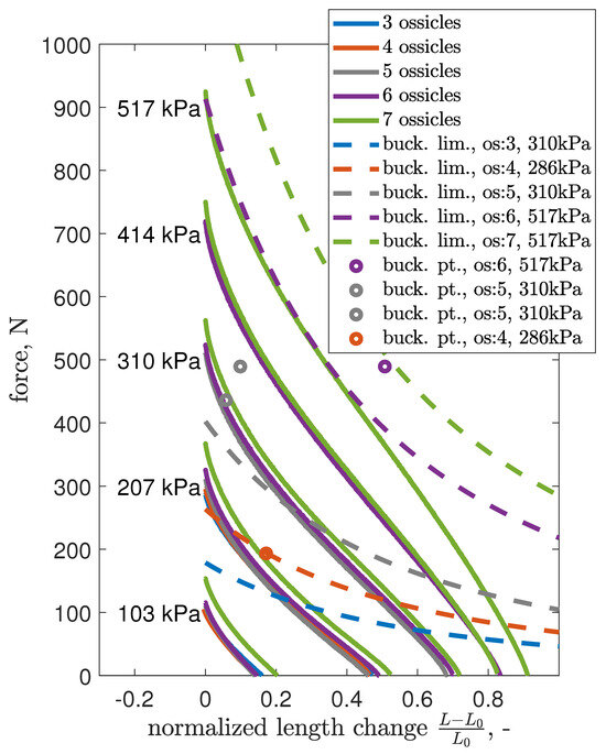
Figure 13.
Averaged axial force response (solid lines) of the EFAM robot with overlaid modeled critical force (dashed lines) at selected pressure levels.
Utilizing Equation (12), we calculated K values for the four identified buckling points, as presented in Table 2, alongside the ossicle-reinforcement coefficient . The most critical load scenario occurred with four ossicles ( and ), indicating that the robot buckled under a smaller load than predicted by an ideal Euler column. As the number of ossicles increased to six, improved to . The averaged experimental K value was with a standard deviation of , and a conservative was selected for further modeling to ensure a lower bound on the critical force.
Figure 13 synthesizes experimental and theoretical results, showing average force responses and critical forces for various ossicle counts. The conservative K value ensures that theoretical buckling limits (dashed lines) intersect with the force response curves (solid lines), indicating potential buckling under corresponding conditions. For instance, with six ossicles at 517 kPa, the proximity of the buckling limit curve to the force response suggests a high likelihood of buckling, as confirmed by observed buckling points. Conversely, the seven-ossicle configuration at 517 kPa demonstrated a safe margin, preventing buckling across all tested pressures.
The modeling, anchored to the least favorable buckling point at kPa, cm, and N, accurately intersects this critical instance, with other points lying above the modeled trends. This alignment reveals that, at lower pressures, buckling tends to occur at minor length changes due to a disproportionate decrease in critical versus EFAM force. The quadratic relationship with the ossicle count further shows this dynamic.
Figure 14 illustrates how ossicle reinforcement enhances buckling resistance, showcasing an approximate four-fold increase in critical force between the three- and seven-ossicle configurations at 517 kPa. This observation aligns with the experimental finding that ossicles contributed to a three-fold rise in blocked force, underscoring the effectiveness of ossicle reinforcement in elevating buckling thresholds and enhancing the robot’s structural resilience under load.
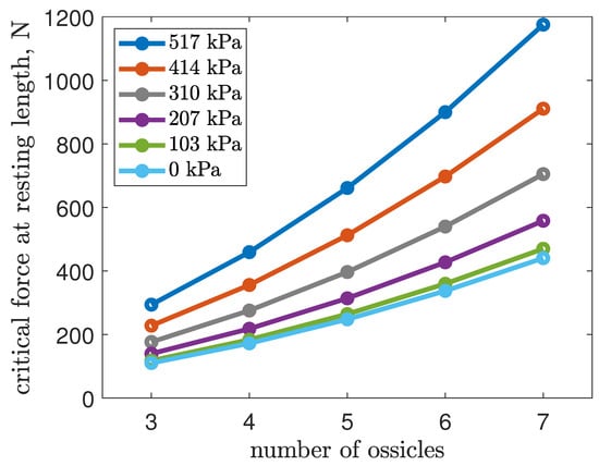
Figure 14.
Modeled critical force at blocked-force condition of the EFAM robot over an internal pressure range of – kPa.
5. Discussion
This study shows the impact of ossicle reinforcement on the axial load performance of EFAM-driven continuum robots. Axial testing revealed a propensity for buckling under load, which was mitigated by the addition of seven ossicles, preventing structural collapse (see Figure 4). The findings indicate that a higher ossicle count enhances the robot’s ability to operate at increased pressures without buckling, thereby improving force transfer capabilities.
Incrementing ossicle numbers correlated with raised maximum operational pressures, suggesting an enhancement in axial force generation capabilities without buckling. This improvement extends to bending scenarios—common operational modes for such robots—indicating that ossicle integration significantly boosts payload performance (Figure A1, Figure A2, Figure A3 and Figure A4).
While ossicle reinforcement modestly increased the blocked force (Figure 9), this effect could stem from a reduced dead-band pressure with more ossicles (Figure 8). Crucially, ossicle addition did not detrimentally affect blocked forces or dead-band pressures, but rather contributed positively. Free extension under no load remained largely unchanged (Figure 10).
The investigation into the robot’s linear stiffness revealed only minor increases with more ossicles, preserving the robot’s inherent softness despite the integration of rigid ossicles (Figure 11 and Figure 12).
Adapting the Euler column model to account for the robot’s variable cross-section and moment of inertia, we established a relationship between ossicle count and the robot’s effective length, influencing buckling behavior. This model, correlating buckling limits with experimental data, underscores the ossicles’ role in enhancing axial performance without compromising the robot’s soft characteristics.
The critical forces for buckling rose with additional ossicles, maintaining the robot’s soft nature. Despite employing an idealized Euler column framework, the model aligned closely with experimental observations, offering valuable insights into the axial buckling limits and the benefits of ossicle reinforcement in EFAM-driven continuum robots.
While ossicle reinforcement enhances the buckling resistance of soft continuum robots, it introduces potential performance drawbacks. Hard structures reduce flexibility, hindering navigation in tight spaces and limiting high-bending motion. In applications involving biological tissues or delicate environments (e.g., medical or agricultural), increased rigidity may impede safe and gentle interaction. Although ossicles significantly increase payload capacity, they add weight, which is disadvantageous in weight-sensitive applications, and affect the response time due to larger inertia. Future studies on payload-carrying robots in confined spaces and delicate environments could investigate the optimization of ossicle design (materials and configurations) to retain flexibility and maneuverability while maintaining buckling resistance. Despite these drawbacks, the benefits of improved buckling resistance and structural robustness outweigh these adverse effects in many practical payload-carrying applications.
6. Conclusions
This research demonstrates that ossicle reinforcement significantly enhances the axial performance of EFAM-driven continuum soft robots, without compromising key performance metrics such as blocked force, free extension, and dead-band pressure. In fact, these aspects show slight improvements with additional ossicles. Notably, a minimal increase in axial stiffness was observed with more ossicles, indicating the reinforcement’s role in maintaining the robot’s inherent softness while significantly boosting its load-bearing capacity. Specifically, the robot reinforced with seven ossicles exhibited a remarkable 320% increase in blocked force capability compared to its three-ossicle counterpart, a testament to the dramatic enhancement in payload-carrying potential supported by visual evidence from bending configurations.
The findings underscore that ossicle reinforcement not only preserves the robot’s axial performance but also effectively mitigates buckling, suggesting that, in designs, where the addition of ossicle mass or localized rigidity does not pose significant trade-offs, integrating numerous ossicles can substantially augment the robot’s ability to transfer force from actuators to the load across a wide operational pressure spectrum without buckling. This study sheds light on the future direction of designing robust, capable, and resilient soft robotic systems. By harnessing ossicle reinforcement, it offers a pathway to surpass current limitations in soft robot performance.
7. Future Work
The outcomes of this study will inform the advancement of payload-carrying EFAM-driven continuum soft robots. Further research specifically focused on the buckling behavior of ossicle-reinforced soft structures will be necessary to delve deeper into the principles of ossicle reinforcement.
Author Contributions
Conceptualization, N.M.W. and J.G.; methodology, N.M.W. and J.G.; software, J.G.; validation, J.G., S.C.B. and N.M.W.; formal analysis, J.G.; investigation, J.G. and S.C.B.; resources, N.M.W.; data curation, J.G.; writing—original draft preparation, J.G.; writing—review and editing, J.G., S.C.B. and N.M.W.; visualization, J.G. and N.M.W.; supervision, N.M.W.; project administration, NMW; funding acquisition, N.M.W. All authors have read and agreed to the published version of the manuscript.
Funding
Research support was provided by the U.S. Office of Naval Research under a Basic Research Challenge grant, award no. N000141712063, titled “SEA-STAR: Soft Echinoderm-Inspired Appendages for Strong Tactile Amphibious Robots”. Any opinion, findings, and conclusions or recommendations expressed herein are those of the authors.
Data Availability Statement
Data are available from the authors upon reasonable request.
Acknowledgments
J.G. acknowledges and thanks the Polish-U.S. Fulbright Commission for granting a Fulbright Scholarship, facilitating graduate studies at the University of Maryland. S.C.B. acknowledges and thanks the Maryland Robotics Center for graduate scholarship support. This research was conducted as part of the doctoral thesis of J.G. at the University of Maryland [32]. We would like to thank the committee members for their guidance and support.
Conflicts of Interest
The authors declare no conflicts of interest. Funders had neither a role in the design of the study, nor in the collection, analyses, or interpretation of data, nor in the writing of the manuscript, nor in the decision to publish results.
Abbreviations
The following abbreviations are used in this manuscript:
| EFAM | Extensile Fluidic Artificial Muscles |
| FAM | Fluidic Artificial Muscles |
| PAM | Pneumatic Artificial Muscle |
Appendix A. Pictographic Data—Spatial Behavior
The robot for which pictographic data were acquired composed of three EFAMs with 3D-printed end fittings. Each muscle measured 11.59 cm in resting length, 2.87 cm resting outer diameter and weighted 43 g. The distance of each muscle from the center was 7.422 cm. Two muscles on the left were pressurized to 551.6 kPa (80 psi) and the muscle on the right was pressurized to 34.5 kPa (5 psi). Except for different EFAM specimens, the ossicles and other parts were the same as those described in the axial experiment. Each ossicle weighted 33.45 g including cable ties. The main robot structure of three EFAMs weighed 129 g with the addition of 33.45 g for each ossicle.
The data were collected for four pressure configurations, which represented operating states such as retracted state, expanded state, and two bending states. In each pressure configuration, three different payload cases were tested: base payload, 401.77 g (I); medium payload, 1050.77 g (II); and large payload, 2794.05 g (III). For each payload case, the robot was reinforced with zero, one, three, and seven ossicles.
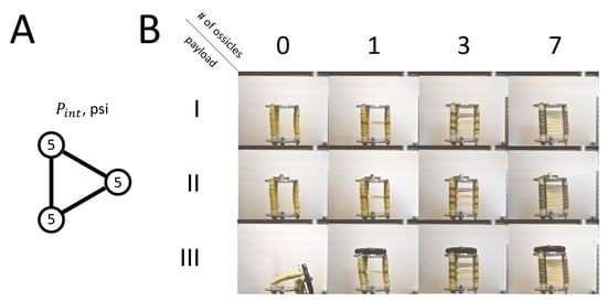
Figure A1.
(A) Configuration diagram showing internal pressure values for each muscle. (B) Pictographic table showing three payload cases (I–III) and four ossicle cases (0, 1, 3, 7).
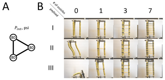
Figure A2.
(A) Configuration diagram showing internal pressure values for each muscle. (B) Pictographic table showing three payload cases (I–III) and four ossicle cases (0, 1, 3, 7).
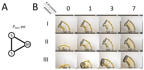
Figure A3.
(A) Configuration diagram showing internal pressure values for each muscle. (B) Pictographic table showing three payload cases (I–III) and four ossicle cases (0, 1, 3, 7).
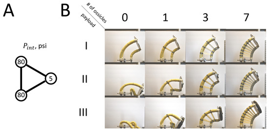
Figure A4.
(A) Configuration diagram showing internal pressure values for each muscle. (B) Pictographic table showing three payload cases (I–III) and four ossicle cases (0, 1, 3, 7).
References
- Davis, S. Pneumatic Actuators. Actuators 2018, 7, 62. [Google Scholar] [CrossRef]
- Majidi, C. Soft Robotics: A Perspective—Current Trends and Prospects for the Future. Soft Robot. 2013, 1, 5–11. [Google Scholar] [CrossRef]
- Trivedi, D.; Rahn, C.D.; Kier, W.M.; Walker, I.D. Soft Robotics: Biological Inspiration, State of the Art, and Future Research. Appl. Bionics Biomech. 2008, 5, 1176–2322. [Google Scholar] [CrossRef]
- Jones, B.A.; Walker, I.D. Practical kinematics for real-time implementation of continuum robots. IEEE Trans. Robot. 2006, 22, 1087–1099. [Google Scholar] [CrossRef]
- Neppalli, S.; Jones, B.; McMahan, W.; Chitrakaran, V.; Walker, I.; Pritts, M.; Csencsits, M.; Rahn, C.; Grissom, M. Octarm—A soft robotic manipulator. In Proceedings of the IEEE/RSJ International Conference on Intelligent Robots and Systems, San Diego, CA, USA, 29 October–2 November 2007; p. 2569. [Google Scholar]
- Webster, R.J., III; Jones, B.A. Design and kinematic modeling of constant curvature continuum robots: A review. Int. J. Robot. Res. 2010, 29, 1661–1683. [Google Scholar] [CrossRef]
- Walker, I.D. Continuous backbone “continuum” robot manipulators. ISRN Robot. 2013, 2013, 1–19. [Google Scholar] [CrossRef]
- Pritts, M.B.; Rahn, C.D. Design of an artificial muscle continuum robot. In Proceedings of the IEEE International Conference on Robotics and Automation, New Orleans, LA, USA, 26 April–1 May 2004; Volume 5, pp. 4742–4746. [Google Scholar]
- McMahan, W.; Chitrakaran, V.; Csencsits, M.; Dawson, D.; Walker, I.D.; Jones, B.A.; Pritts, M.; Dienno, D.; Grissom, M.; Rahn, C.D. Field trials and testing of the OctArm continuum manipulator. In Proceedings of the 2006 IEEE International Conference on Robotics and Automation—ICRA 2006, Orlando, FL, USA, 15–19 May 2006; pp. 2336–2341. [Google Scholar]
- Trivedi, D.; Lotfi, A.; Rahn, C.D. Geometrically Exact Models for Soft Robotic Manipulators. Trans. Rob. 2008, 24, 773–780. [Google Scholar] [CrossRef]
- Chawla, A.; Frazelle, C.; Walker, I. A Comparison of Constant Curvature Forward Kinematics for Multisection Continuum Manipulators. In Proceedings of the 2018 Second IEEE International Conference on Robotic Computing (IRC), Laguna Hills, CA, USA, 31 January–2 February 2018; pp. 217–223. [Google Scholar]
- Giannaccini, M.E.; Xiang, C.; Atyabi, A.; Theodoridis, T.; Nefti-Meziani, S.; Davis, S. Novel Design of a Soft Lightweight Pneumatic Continuum Robot Arm with Decoupled Variable Stiffness and Positioning. Soft Robot. 2018, 5, 54–70. [Google Scholar] [CrossRef]
- Guan, Q.; Sun, J.; Liu, Y.; Wereley, N.M.; Leng, J. Novel Bending and Helical Extensile/Contractile Pneumatic Artificial Muscles Inspired by Elephant Trunk. Soft Robot. 2020, 7, 597–614. [Google Scholar] [CrossRef] [PubMed]
- Tomholt, L.; Friesen, L.J.; Berdichevsky, D.; Fernandes, M.C.; Pierre, C.; Wood, R.J.; Weaver, J.C. The structural origins of brittle star arm kinematics: An integrated tomographic, additive manufacturing, and parametric modeling-based approach. J. Struct. Biol. 2020, 11, 107481. [Google Scholar] [CrossRef] [PubMed]
- Pillsbury, T. Soft Robotic Appendages Using Pneumatic Artificial Muscles. Ph.D. Thesis, University of Maryland, College Park, MD, USA, 2018. [Google Scholar]
- Olson, G.; Woronowicz, B.; Mengüç, Y. Characterization of a Class of Soft Bending Arms. In Proceedings of the 2019 2nd IEEE International Conference on Soft Robotics (RoboSoft), Seoul, Republic of Korea, 14–18 April 2019; pp. 462–469. [Google Scholar] [CrossRef]
- Olson, G.; Hatton, R.L.; Adams, J.A.; Mengüç, Y. An Euler–Bernoulli beam model for soft robot arms bent through self-stress and external loads. Int. J. Solids Struct. 2020, 207, 113–131. [Google Scholar] [CrossRef]
- Godage, I.S.; Medrano-Cerda, G.A.; Branson, D.T.; Guglielmino, E.; Caldwell, D.G. Dynamics for variable length multisection continuum arms. Int. J. Robot. Res. 2016, 35, 695–722. [Google Scholar] [CrossRef]
- Ansari, Y.; Manti, M.; Falotico, E.; Cianchetti, M.; Laschi, C. Multiobjective Optimization for Stiffness and Position Control in a Soft Robot Arm Module. IEEE Robot. Autom. Lett. 2018, 3, 108–115. [Google Scholar] [CrossRef]
- Sridar, S.; Majeika, C.J.; Schaffer, P.; Bowers, M.; Ueda, S.; Barth, A.J.; Sorrells, J.L.; Wu, J.T.; Hunt, T.R.; Popovic, M. Hydro Muscle—A novel soft fluidic actuator. In Proceedings of the 2016 IEEE International Conference on Robotics and Automation (ICRA), Stockholm, Sweden, 16–21 May 2016; pp. 4014–4021. [Google Scholar] [CrossRef]
- Skorina, E.H.; Onal, C.D. Soft Pneumatic Actuators: Modeling, Control, and Application. In Smart Materials: Considerations on Earth and in Space; Rasmussen, L., Ed.; Springer International Publishing: Cham, Switzerland, 2022; pp. 129–219. [Google Scholar] [CrossRef]
- Kim, J.Y.; Mazzoleni, N.; Bryant, M. Modeling of Resistive Forces and Buckling Behavior in Variable Recruitment Fluidic Artificial Muscle Bundles. Actuators 2021, 10, 42. [Google Scholar] [CrossRef]
- Mazzoleni, N.; Kim, J.Y.; Bryant, M. Motor unit buckling in variable recruitment fluidic artificial muscle bundles: Implications and mitigations. Smart Mater. Struct. 2022, 31, 035004. [Google Scholar] [CrossRef]
- Hocking, E.G.; Wereley, N.M. Analysis of nonlinear elastic behavior in miniature pneumatic artificial muscles. Smart Mater. Struct. 2012, 22, 014016. [Google Scholar] [CrossRef]
- Woods, B.K.S.; Gentry, M.F.; Kothera, C.S.; Wereley, N.M. Fatigue life testing of swaged pneumatic artificial muscles as actuators for aerospace applications. J. Intell. Mater. Syst. Struct. 2012, 23, 327–343. [Google Scholar] [CrossRef]
- Garbulinski, J.; Balasankula, S.C.; Wereley, N.M. Characterization and Analysis of Extensile Fluidic Artificial Muscles. Actuators 2021, 10, 26. [Google Scholar] [CrossRef]
- Kothera, C.; Jangid, M.; Sirohi, J.; Wereley, N. Experimental characterization and static modeling of McKibben actuators. J. Mech. Des. Trans. ASME 2009, 131, 091010. [Google Scholar] [CrossRef]
- Pillsbury, T.E.; Wereley, N.M.; Guan, Q. Comparison of contractile and extensile pneumatic artificial muscles. Smart Mater. Struct. 2017, 26, 095034. [Google Scholar] [CrossRef]
- Chou, C.P.; Hannaford, B. Measurement and modeling of McKibben pneumatic artificial muscles. IEEE Trans. Robot. Autom. 1996, 12, 90–102. [Google Scholar] [CrossRef]
- Raj, P.P.; Ramasamy, V. Strength of Materials, 1st ed.; Dorling Kindersley: New Delhi, India, 2012. [Google Scholar]
- Popov, E.P. Mechanics of Materials, 2nd ed.; Civil Engineering and Engineering Mechanics Series; Prentice-Hall, Inc.: Englewood Cliffs, NJ, USA, 1976. [Google Scholar]
- Garbulinski, J. Extensile Fluidic Artificial Muscles in Payload-Carrying Continuum Soft Robots. Ph.D. Thesis, University of Maryland, College Park, MD, USA, 2023. [Google Scholar]
Disclaimer/Publisher’s Note: The statements, opinions and data contained in all publications are solely those of the individual author(s) and contributor(s) and not of MDPI and/or the editor(s). MDPI and/or the editor(s) disclaim responsibility for any injury to people or property resulting from any ideas, methods, instructions or products referred to in the content. |
© 2024 by the authors. Licensee MDPI, Basel, Switzerland. This article is an open access article distributed under the terms and conditions of the Creative Commons Attribution (CC BY) license (https://creativecommons.org/licenses/by/4.0/).