Article

Structural Design and Control Performance Study of Flexible Finger Mechanisms for Robot End Effectors

1
School of Mechanical and Power Engineering, Henan Polytechnic University, Jiaozuo 454003, China
2
School of Automation Science and Electrical Engineering, Beihang University, Beijing 100191, China
3
Pingyuan Filter Co., Ltd., Xinxiang 453000, China
*
Author to whom correspondence should be addressed.
Actuators 2024, 13(7), 271; https://doi.org/10.3390/act13070271
Submission received: 7 June 2024 / Revised: 9 July 2024 / Accepted: 16 July 2024 / Published: 18 July 2024
(This article belongs to the Special Issue Advancement in the Design and Control of Robotic Grippers)

Abstract

:
Most traditional rigid grippers can cause damage to the surface of objects in actual production processes and are susceptible to factors such as different shapes, sizes, materials, and positions of the product. This article studies a flexible finger for flexible grippers, more commonly described as PneuNet, designs the structure of the finger, discusses the processing and manufacturing methods of the flexible finger, and prepares a physical model. The influence of structural parameters such as the thickness of the flexible finger and the angle of the air chamber on the bending performance of the finger was analyzed using the Abaqus simulation tool. An RBF-PID control algorithm was used to stabilize the internal air pressure of the flexible fingers. A flexible finger stabilization experimental platform was built to test the ultimate pressure, ultimate bending angle, and end contact force of the fingers, and the simulation results were experimentally verified. The results show that when the thickness of the flexible finger is 2 mm and the air chamber angle is 0 deg, the maximum bending angle of the flexible finger can reach about 136.3°. Under the same air pressure, the bending angle is inversely correlated with the air chamber angle and finger thickness. The experimental error of the bending angle does not exceed 3%, which is consistent with the simulation results as a whole. When the thickness is 2 mm, the maximum end contact force can reach about 1.32 N, and the end contact force decreases with the increase in the air chamber angle. The RBF-PID control algorithm used has improved response speed and a better control effect compared to traditional PID control algorithms. This article provides a clear reference for the application of flexible fingers and flexible grippers, and this research method can be applied to the analysis and design optimization of other soft brakes.

1. Introduction

The gripping mechanism of robot end effectors is generally a multi-finger combination structure, which can meet the functional requirements of sample collection and placement in land, ocean, space, and other application scenarios due to its inherent structural convergence characteristics. In the collection or detection of small marine plant or animal samples near the coast, a flexible end effector gripping mechanism is often needed, which can reduce the mechanical damage to the collected samples and maximize the preservation of the original form and quality of the collected samples. The common multi-finger gripping mechanisms are generally rigid or semi-rigid structures, which are more prone to damaging the surface tissue of the sample and its epidermal morphology compared to flexible structures. The design, motion control, and power energy supply of multi-finger gripping mechanisms with fully flexible structures are becoming research hotspots in this field.
Grasping actions are essential in daily life and various industries. With the continuous progress of technology, using robot grabbing instead of human grabbing is an unchangeable development trend. Mechanical grippers are the direct way and important link for robots to contact the natural environment. The quality of mechanical grippers directly affects the operability and gripping ability of robots.
It may be quite complex to apply seemingly simple grasping tasks to robots. Based on past experience, rigid materials are usually used to make mechanical grippers, in order to obtain robot grasping systems with higher predictability and accuracy. The modeling of these systems is usually relatively easy. However, due to the use of rigid materials, such mechanical grippers often suffer from issues such as high self-weight and easy damage to the surface of objects. In traditional grasping tasks, rigid mechanical grippers or vacuum suction cups are commonly used to achieve corresponding functions [1,2], but these methods are often affected by factors such as different shapes, sizes, materials, and positions of the product.
The flexible gripper is a new type of gripping mechanism that has emerged in recent years [3]. Unlike traditional gripping mechanisms, it uses flexible fingers to grip products. Due to its material characteristics and soft contact with the product, it will not cause rigid damage such as scratches, and can form an envelope structure to grip the product without the need for precise pre-set dimensions, positions, shapes, etc. Flexible grippers are increasingly being used in our daily life and production. Many scholars have achieved clear results in the research of flexible grippers, covering various fields such as structure, materials, and so on [4].
In terms of structure, there are biomimetic grasping mechanisms inspired by nature, such as octopus-like grasping mechanisms [5], chameleon-like grasping mechanisms [6], human-like swallowing grasping mechanisms [7], and hand-like grasping mechanisms [8]. There are also improved flexible end effectors based on traditional end effectors, such as clamp claws [9], cage claws [10], and interlocking claws [11].
In terms of materials, materials such as dielectric elastomers [12], composite materials [13], and silicone rubber [14] are commonly used to make flexible grippers due to their flexibility. The elastic modulus of these materials is much lower than that of rigid robotic arms, and they are similar to biological structures such as skin and muscles, so they have good flexibility and adaptability. Merces et al. introduced an innovative strain engineering dynamic shape material that can achieve multi-dimensional shape modulation, and combined these modulations to construct fine-grained adaptive microstructures [15]. The study shows that smart material systems can support ultra-flexible 4D microelectronics well. Zhu et al. introduced an integrated fabrication–design–actuation methodology of an electrothermal micro-origami system [16], which can be applied to metamaterials and micro-robots. Moreover, 3D printing technology is often used in practical production due to its wide applicability, convenience, and efficiency [17].
Among numerous flexible gripper structures, cage-type grippers are increasingly being used in our daily life and production due to their advantages such as good enveloping, strong adaptability, wide application range, and convenient operation. For example, for grasping flexible food, vulnerable electronic devices, and objects of the opposite sex, it is necessary to further study the key components of cage-type grippers, such as flexible fingers.
Xavier et al. summarized the development of soft pneumatic actuators and robots to date, covering the design, modeling, manufacturing, driving, characterization, sensing, control, and application of soft robot equipment [18]. Pagoli et al. focused on the behavior and mechanical properties of various types of organosilicon in the SFA literature [19]. Marchese et al. explored three feasible actuator forms composed entirely of soft silicone rubber and provided a method for designing and manufacturing soft fluid elastomer robots [20]. Hu et al. investigated the influence of various design parameters on the driving performance of pneumatic network actuators (PNA), optimized their structure using finite element method (FEM), and then quantified the performance of the resulting actuator topology through experiments [21].
Xavier et al. proposed a parameter selection method for pneumatic soft robot systems that considers the required closed-loop pressure response, and evaluated PI controllers with anti-saturation and switch controllers with hysteresis [22]. Joshi et al. proposed a normalized model for the pressure dynamics of soft actuators and quantified the relationship between PSS parameters, soft actuator design parameters, and dynamic performance indicators of rise time, fall time, and actuation frequency [23]. And the experimental protocol for the flow characteristics of PSS components and the valve control strategy for the maximum driving frequency were defined [24]. Pengfei Qian et al. proposed a high-performance mixed Gaussian mutation particle swarm optimization algorithm with self-shrinking search space, which was successfully used for optimizing the parameters of motion control systems and achieving the intelligent optimization of self-made cylinder piston sealing grooves [25]. At the same time, they proposed a new type of double-acting air-floating frictionless cylinder, based on which a force servo system can achieve an output force control accuracy of about 0.02% [26].
Yan Shi et al. investigated a difunctional pneumatic sensor for simultaneously monitoring position and speed [27]. The pneumatic adaptive finite time contact force tracking control was also discussed [28]. Changhui Wang et al. studied the output feedback control of a pneumatic servo system [29,30]. Wang Na et al. designed a fuzzy parameter adaptive controller for pneumatic control to optimize the control performance [31].
The main research object of this article is a key pneumatic flexible finger, which is particularly important for the application of pneumatic-cage-type grippers. Firstly, the structure of the flexible finger was designed, and a physical finger was prepared by a mold casting method. We tested the material parameters, established a three-dimensional model of a single flexible finger, and conducted finite element analysis to study the relationship between the structural parameters of the single flexible finger and its bending performance. We also built an experimental platform for experimental testing, and explored the influence of finger structural parameters on the contact force at the end of the finger. In order to ensure the stability of the internal air pressure of the finger, we combined an RBF neural network with a traditional PID control algorithm and used a flexible finger stabilization control algorithm based on an RBF neural network tuning a PID control algorithm, in order to provide some reference for the design and application of flexible fingers and flexible grippers.

2. Materials and Methods

2.1. Flexible Finger Structure Design

Flexible grippers are among the important branches of robot end effectors. As a key component of flexible grippers, flexible fingers directly affect the gripping performance of flexible grippers. In both domestic and foreign research, corrugated-tube-type flexible fingers have attracted widespread attention from scholars due to their simple structure, high work efficiency, and low cost. This paper designs a full silicone flexible finger based on a multi-chamber pneumatic grid, which is divided into four parts, an air inlet, air chamber, deformation layer, and limiting chamber, as shown in Figure 1. There are a series of small cavities with the same structure inside the deformation layer, and it should be noted that these small cavities are arranged at equal distances and connected to each other. When inflating the inside of the flexible finger, the gas will quickly fill the entire cavity through the channel, ignoring the transient gas impact. Due to Pascal’s law, the pressure in the entire internal cavity is equal, and the small cavity will expand and deform under the action of air pressure, driving the deformation layer to expand and deform, and the overall length to become longer. At this time, due to the lack of an air cavity on the limiting layer side, the degree of deformation is not obvious, causing the flexible finger to bend and deform towards the limiting layer side. Through the cooperation of multiple fingers, the grasping operation of the object is achieved.
Due to the fact that the objects being grasped are generally fragile and easily damaged items, flexible fingers should be made of relatively soft and flexible materials to have good bending and adaptive abilities. In this article, silicone material with a Shore hardness of 0020 is selected. In order to facilitate the calculation of inflation volume, a constant internal air chamber volume method is adopted. The total length a of the air chamber is 100 mm, the width b is 20 mm, and the height h is 10 mm. The length l and height t of the small air chamber are both 5 mm. The preliminary design of the small air chamber is a rectangular structure, and the angle of the air chamber is expressed by the angle between the side of the finger and the vertical line. The angle of the air chamber here is 0 deg, and the overall shell thickness d of the flexible finger is preliminarily set at 2 mm.

2.2. Design and Manufacture of Finger Molds and Flexible Fingers

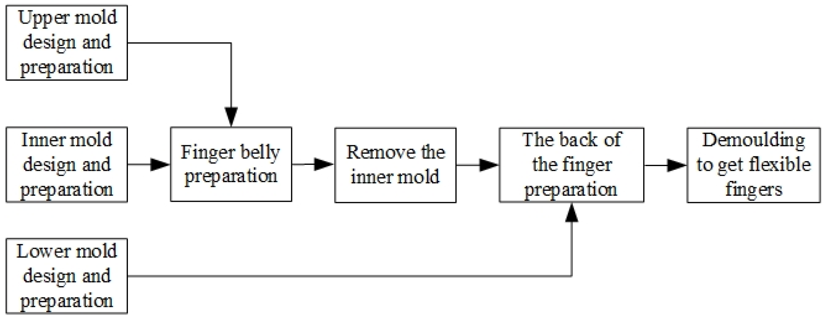
Due to the complex internal cavity structure of the designed flexible finger and the use of soft silicone material, it is difficult to directly process the flexible finger structure using traditional processing methods. Currently, the processing methods for soft materials include 3D printing technology, wax loss casting technology, and the shape deposition method (SDM). This article uses an effective method for making soft material structures—mold casting method, and the process flow of this method is shown in Figure 2.
Firstly, 3D printing technology is used to print out the mold, and then the flexible fingers are obtained by pouring and shaping. The specific pouring process is as follows. The upper mold and the inner mold are combined to construct a flexible finger belly. After the flexible finger belly is preliminarily formed, the inner mold is taken out, and then the lower mold and upper mold are combined again to construct a flexible finger back. Finally, the flexible finger is demolded to obtain a flexible finger.
The finger mold is divided into three parts: the upper mold, the inner mold, and the lower mold. The combination of the three parts can form a complex internal structure of a flexible finger. The structural parameters of the flexible fingers can be changed by changing the mold structure parameters. In this article, 12 sets of molds are preliminarily designed, and the corresponding formed flexible fingers are divided into three thicknesses: 1 mm, 2 mm, and 3 mm. Each thickness corresponds to four chamber angles: 0 deg, 15 deg, 30 deg, and 42 deg.
The production method of the mold adopts 3D printing technology, which has advantages such as high processing efficiency and low cost. The printing materials are PLA and TPU. Compared with TPU molds, PLA molds have a harder characteristic, but the disadvantage is that they are brittle and difficult to demold, while TPU is relatively soft and has a certain degree of toughness, making demolding convenient. Therefore, PLA material was selected to print the upper mold and TPU material was used to print the inner mold and lower mold.
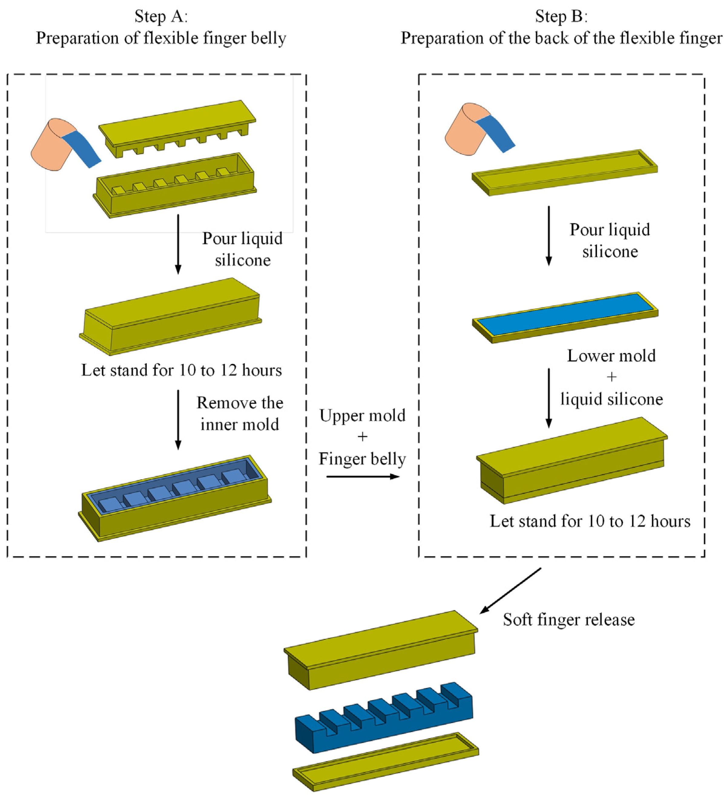
After the above molds had been obtained for pouring, silicone material with a Shore hardness of 0020 was selected and the flexible finger was made using the mold casting method. The production process is shown in Figure 3.
First, to perform step A, the selected silicone material was poured evenly and gently into the upper mold, and then allowed to stand for 1 min. After the liquid became stable and no longer flowed, the inner mold was slowly pressed horizontally inside the upper mold, and the inner mold was aligned with the edge of the upper mold. The excess silicone material was extruded to form an inner cavity filled with silicone material between the two, and time was allowed for the silicone material to cure. The curing time is related to the ambient temperature, whereby the higher the temperature, the shorter the time required, generally 10 to 12 h. As mentioned earlier, TPU is easier to release than PLA, so it was necessary only to remove the inner mold, and the cured silicone material will continue to closely fit the inner surface of the upper mold to complete the preparation of flexible finger belly.
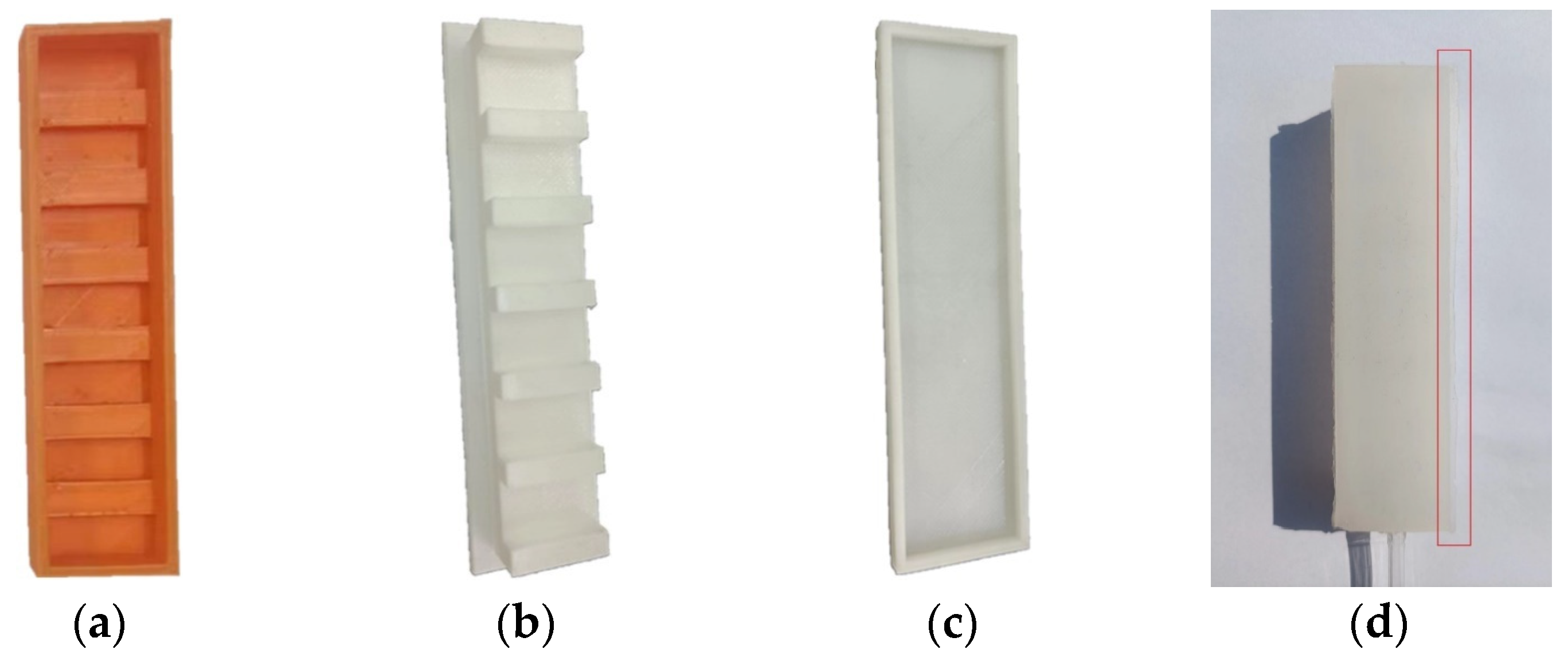
After the preparation of the flexible finger belly, step B was carried out. The silicone material was poured into the lower mold. After the liquid was stabilized, the upper mold and the inner finger belly were reversed onto the lower mold, and the edges were aligned. After the finger was made, the edge was usually accompanied by a thin edge. It was necessary to trim the flexible finger and remove the thin edge to avoid it affecting the final experimental effect. The physical objects of the fingers and molds are shown in Figure 4.

3. Simulation and Experiment

3.1. Simulation Analysis of Flexible Finger

3.1.1. Experimental Testing of Material Parameters of Standard Samples

The silicone flexible finger produced in this article is a hyperelastic material, which means its deformation situation is usually difficult to predict and complex. Finite element analysis is an effective method for predicting model mechanics and deformation analysis. This article uses Abaqus 2022 simulation analysis software to simulate and analyze the nonlinear deformation of the flexible fingers under variable structural parameters and internal pressure.
Before simulation, it is necessary to obtain the specific parameters of the material. The flexible fingers in this article are made entirely of silicone, i.e., of a single material forming a whole. By consulting the relevant standards, the design material sample is shown to be dumbbell shaped.
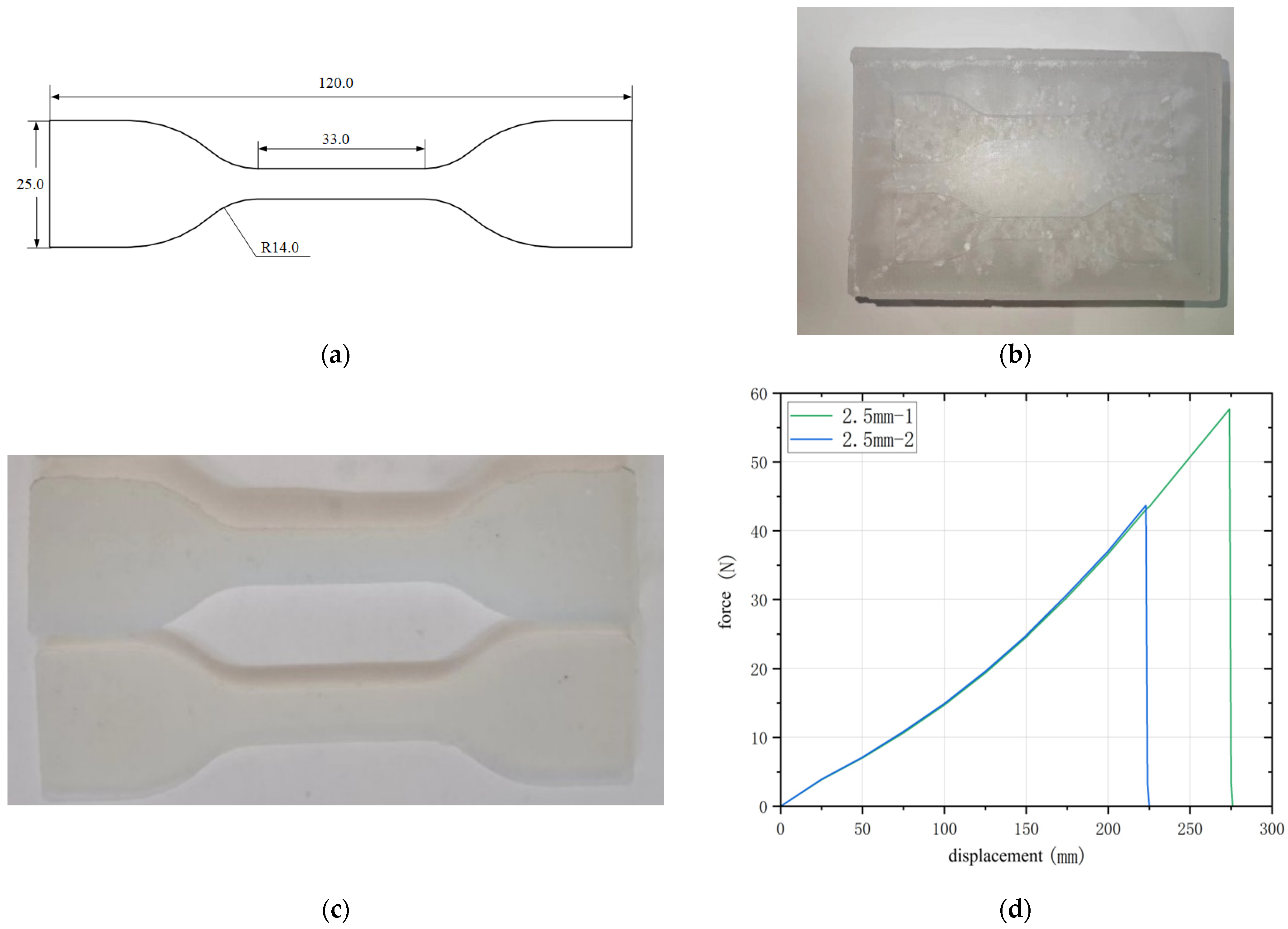
Firstly, the wax casting method was used to heat the solid wax block in a water bath to obtain liquid wax. Then, it was poured into a pre-prepared silicone mold. Compared with other molds, the biggest advantage of silicone molds is that they are easy to demold. After natural cooling, we obtained a square wax block. The surface of the wax block was milled flat using a carving machine, and then the tool path was edited using ArtCAM 2018 software to carve the sample wax groove required in this article onto the surface of the wax block. The selected silicone material was slowly and evenly poured into the sample wax groove, and the dumbbell-shaped silicone sample was obtained after the silicone gel was cured. The sample was subjected to equiaxed tensile testing using a universal tensile machine to obtain the required force displacement curve. The material density can also be obtained through mass volume calculation. The size, preparation, and tensile test of dumbbell-shaped silicone samples are shown in Figure 5. The thickness of the dumbbell-shaped silicone sample is 2 mm.

3.1.2. Simulation Analysis of Mechanical Parameters of Flexible Fingers

The silicone rubber used in this article has the characteristics of high flexibility, high elasticity, and high ductility. Its stress–strain relationship is not a simple linear correspondence, so a superelastic material model is used for simulation. Considering silicone rubber material as isotropic and incompressible, a phenomenological model based on strain energy function can describe silicone deformation, and the material constitutive relationship is represented by strain energy density function W :
W = W ( I 1 , I 2 , I 3 ) I 1 = λ 1 2 + λ 2 2 + λ 3 2 I 2 = λ 1 2 λ 2 2 + λ 2 2 λ 3 2 + λ 1 2 λ 3 2 I 3 = λ 1 2 λ 2 2 λ 3 2 λ i = 1 + γ i
In the formula, I 1 , I 2 , and I 3 are deformation tensor invariants; λ 1 , λ 2 , and λ 3 are the main elongation ratio; and γ i is the main strain.
For the incompressible rubber materials, I 3 = λ 1 2 λ 2 2 λ 3 2 = 1 .
The typical Yeoh model can describe other mechanical behaviors using simple uniaxial tensile tests, and its strain energy density function model can be expressed as:
W = i = 1 N C i 0 ( I 1 3 ) i + k = 1 N 1 d k ( J 1 ) 2 k
In the formula, N , C i j , and d k are material parameters determined by experiments.
The initial shear modulus μ = 2 C 10 , incompressible material J = 1 , and typical binomial parameter form can be expressed as:
W = C 10 ( I 1 3 ) + C 20 ( I 1 3 ) 2
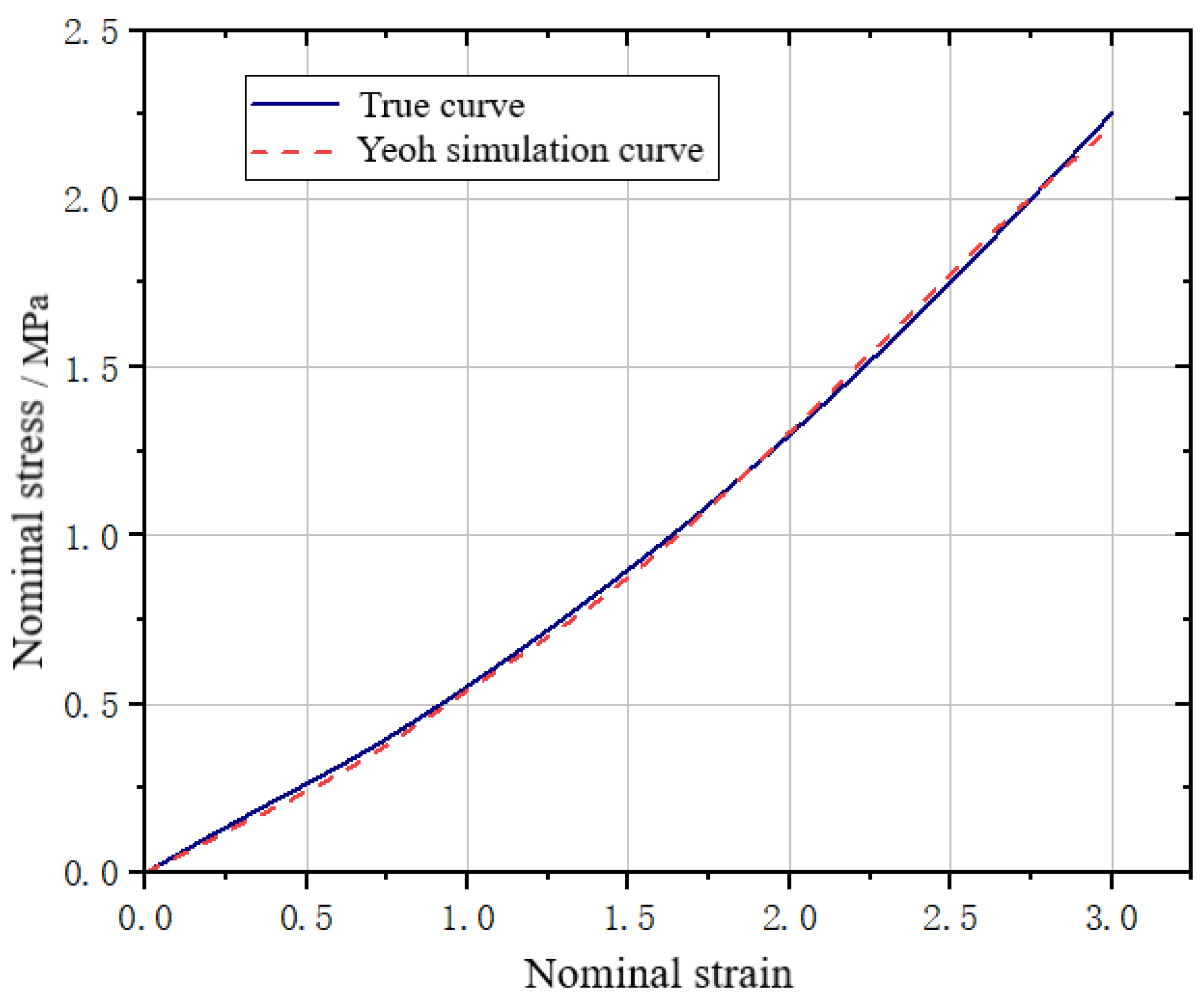
Abaqus was used for the simulation analysis, and the stress–strain data collected in the previous section were incorporated into the second-order expansion of the Yeoh model. The nominal stress and strain were then incorporated into the Abaqus material properties for parameter identification. The identification results are shown in Figure 6.
To establish a three-dimensional model of a flexible finger in Abaqus, we added the obtained material properties, split the unit volume, and determined the mesh accuracy. We used hexahedral elements for the mesh division, applied fixed constraints to one end of the flexible finger as the fixed end, and applied pressure loads to the internal surface to simulate real air pressure. It should be noted that there is a gravity influence in the actual experimental process. In order to better conform to the actual experimental situation, it is necessary to set the gravity acceleration to 9.80665 m/s2.
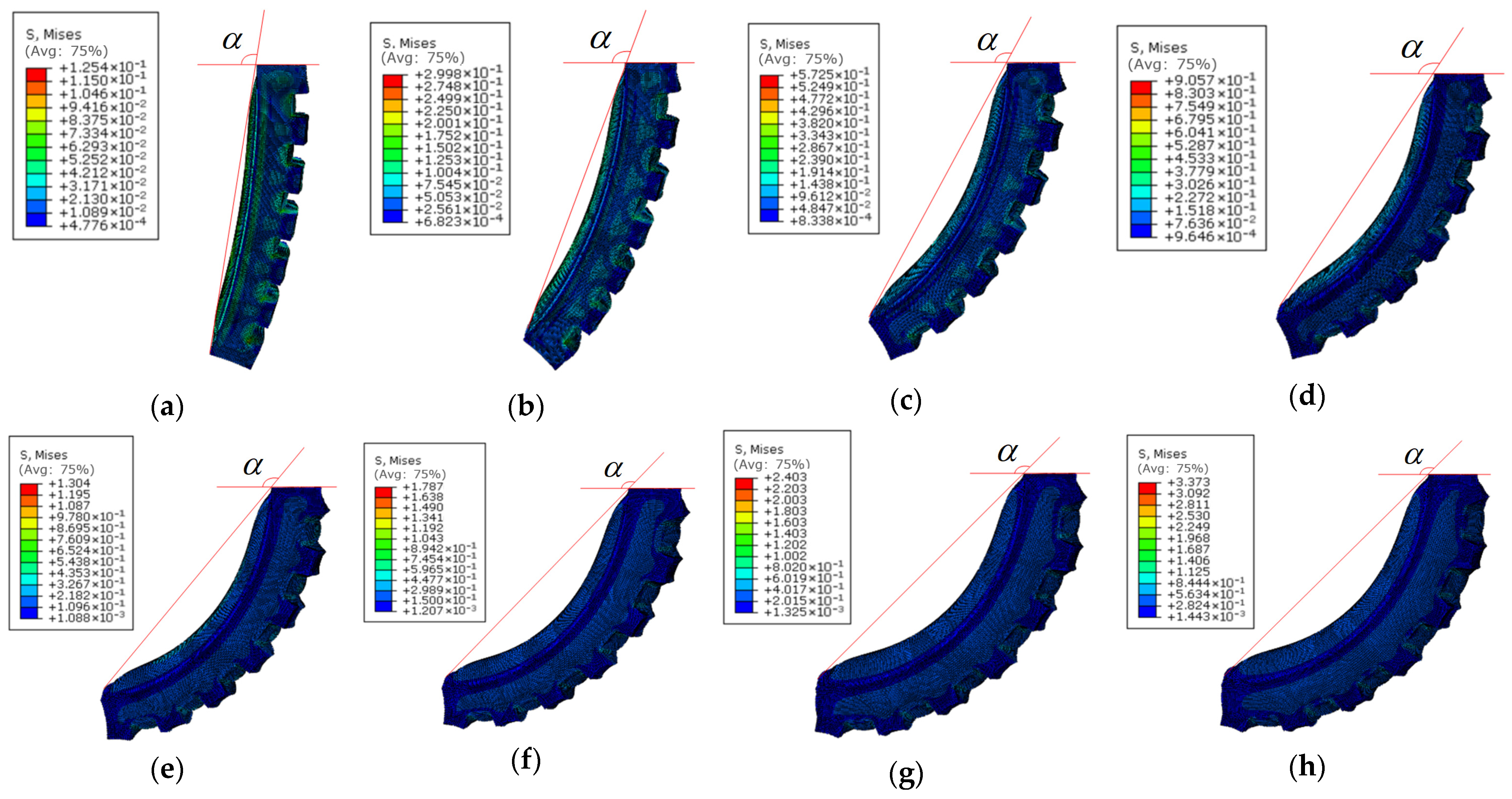
We set the finger thickness to 2 mm, the air chamber angle to 0 deg, and apply internal air pressure of 0~46 kPa with intervals of 2 kPa. The actual working surface of the flexible finger was on the limiting layer side, and the angle between the fingertip on the limiting layer side and the fixed end of the finger was taken as the bending angle α. We used the measurement tool of Abaqus simulation software to calculate the bending angle α. The larger the bending angle α, the greater the degree of bending of the flexible finger. The simulation diagram is shown in Figure 7.

3.1.3. Influence of Finger Cavity Angle on Flexural Properties of Flexible Fingers

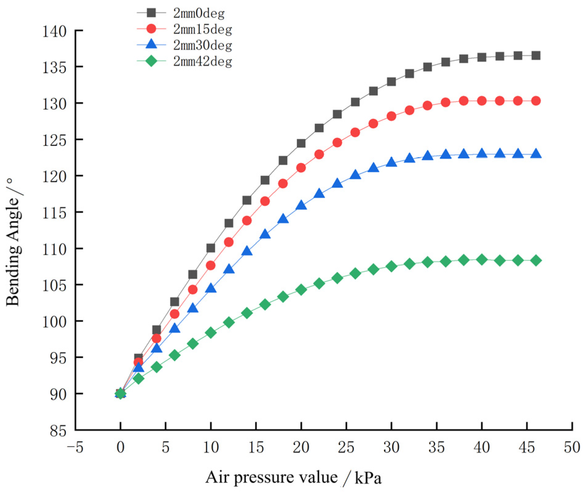
The thickness of the flexible finger was kept as 2 mm, and the angle of the finger air cavity was set to four groups, namely, 0 deg, 15 deg, 30 deg, and 42 deg, respectively. The internal pressure was applied from 0 to 46 kPa, and the application interval was 2 kPa. The simulation results are shown in Figure 8.
The following conclusions can be drawn from Figure 8. The bending angle of the flexible finger decreases with the increase in the angle of the air chamber. This reduction is nonlinear, and the reduction rate increases with the increase in the angle of the air chamber. The maximum bending angle at 0 deg is about 136.3° and the maximum bending angle at 42 deg is about 108.2°.

3.1.4. Influence of Finger Thickness on Flexural Properties of Flexible Fingers

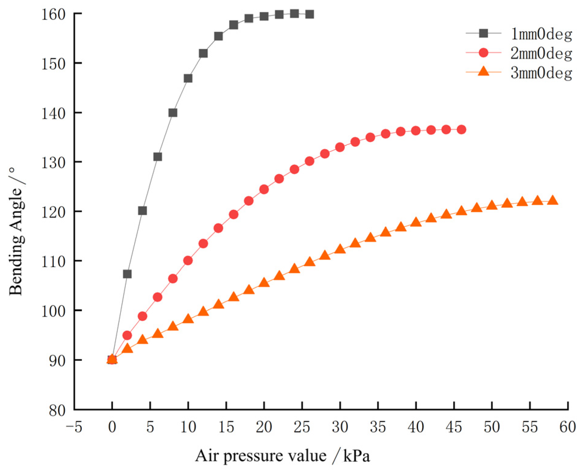
We kept the angle of the air chamber of the flexible finger as 0 deg, and set the thick-ness of the finger as three groups, 1 mm, 2 mm and 3 mm, respectively. Because the change in the thickness of the flexible finger has a great impact on the ultimate pressure it can withstand, the internal pressure range of the three groups of fingers was set accordingly. When the thickness was 1 mm, the internal pressure was 0~26 kPa; when the thickness was 2 mm, the internal pressure was 0~46 kPa. When the thickness was 3 mm, the internal applied pressure ranged from 0 to 58 kPa, and the application interval was 2 kPa in all cases. The simulation results are shown in Figure 9.
The following conclusions can be drawn from Figure 9. The bending angle of the flexible finger decreases with the increase in finger thickness, and this reduction is also nonlinear, and the reduction rate decreases with the increase in finger thickness. The maximum bending angle at 1 mm is about 159.4° and the maximum bending angle at 3 mm is about 122.1°.

3.2. Mechanical Properties of Flexible Fingers

3.2.1. Experimental Platform Construction

According to the control requirements and structural characteristics of the flexible fingers, this paper constructed an experimental platform that could obtain the pressure of the air chamber in real time and control the pressure of the air chamber by adjusting the micro-pump. This experimental platform could realize the pressure control of the flexible fingers and measure the real-time bending angle α of the fingers, so as to further study the principle of the experimental platform, as shown in Figure 10.
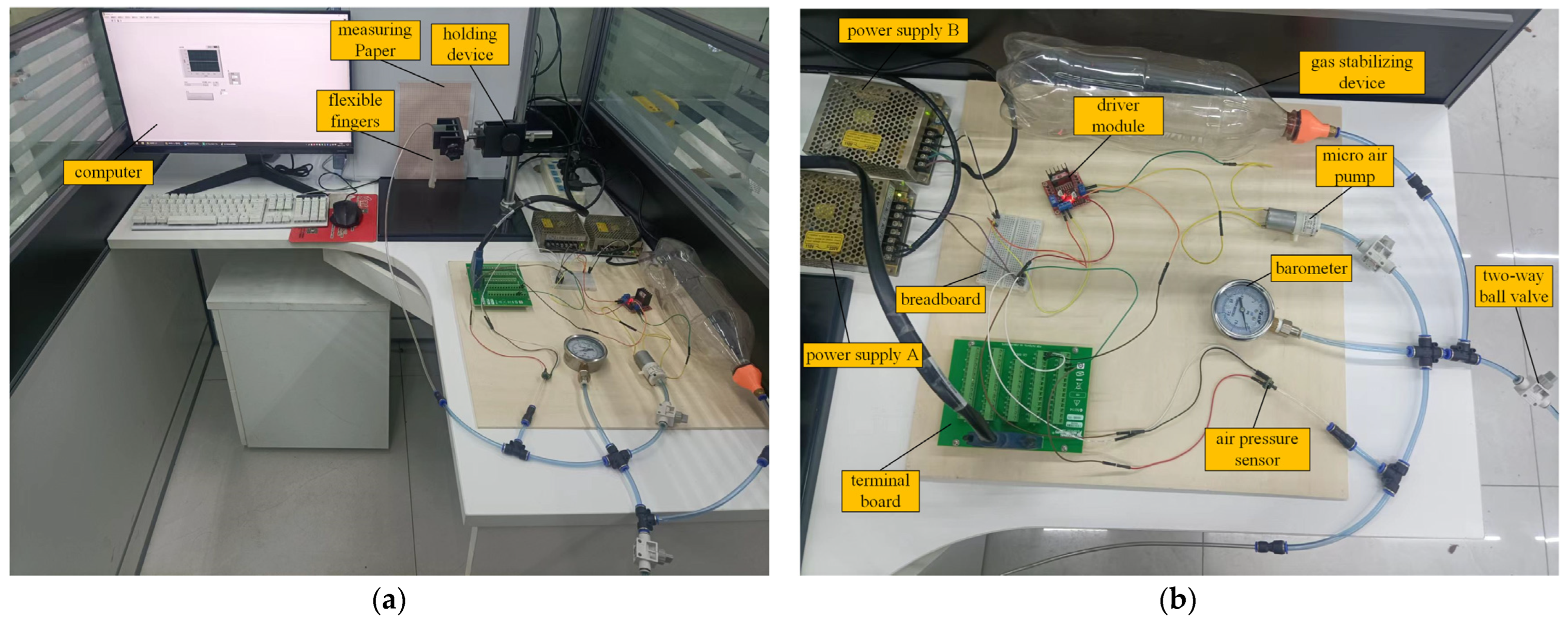
As shown in Figure 10, the pressure sensor was used to collect the internal pressure of the flexible finger in real time, the analog value obtained was transferred to the computer through the PCI-E 6353 data acquisition card, the real-time pressure value was obtained through the internal program of the computer for digital-to-analog conversion, and the PID adjustment to the pressure was performed through the internal program of the computer. The output result was sent to the drive module through the PCI-E 6353 data acquisition card, which drives the micro-air pump to supply gas, and realizes the stable control of the internal pressure of the flexible finger. The power supply provided power to the devices, the barometer corrected the internal pressure value, the gas-stabilizing device prevented the pressure from changing too much, and the two-way ball valve realized pressure relief after the end of the experiment. The holding device realized the clamping and fixing of the fixed end of the flexible finger. When the flexible finger was inflated and bent, the bending angle of the finger could be calculated by using the measuring coordinate paper, and then the bending deformation degree of the flexible finger could be measured.
The basic experimental equipment included power supply A, power supply B, terminal board, breadboard, drive module, pressure sensor, micro-air pump, two-way ball valve, barometer, gas-stabilizing device, holding device, measuring coordinate paper, and computer. After the fabrication of the flexible finger was completed, the experimental platform was finally built with the corresponding trachea air path and the above experimental equipment. The parameters of the experimental equipment are shown in Table 1, and the physical diagram of the experimental platform is shown in Figure 11.

3.2.2. The Ultimate Pressure and Bending Angle of Fingers

Flexible fingers usually have different material choices, different manufacturing processes, and different structural parameters, and the pressure range they can withstand is quite different. In order to carry out the subsequent experiments smoothly, it was necessary to conduct a preliminary pre-experiment on the ultimate pressure of the flexible fingers in this paper, so as to obtain the ultimate pressure of the flexible fingers.
In this paper, there were 12 groups of flexible fingers with different structural parameters, thickness of 1 mm, 2 mm and 3 mm, and the angle of the air cavity of 0 deg, 15 deg, 30 deg and 42 deg. This paper needed to obtain 12 groups of different ultimate pressures. In order to avoid the influence of uncertain factors, the five identical fingers were made for each group of flexible fingers with the same structural parameters. Then, the average of the five limit pressures was taken as the limit pressure of the flexible finger.
Taking the flexible fingers with a thickness of 2 mm and an angle of 0 deg as an example, five flexible fingers with the same structure were made and inflated until they were damaged. The results showed that the damaged parts of the flexible fingers with the same structure were random. The preliminary analysis may be related to uncertain factors such as ambient temperature, humidity, and air pressure at the time of production. Even if the damaged parts had some randomness, the limit pressure of the flexible finger was almost the same when it was damaged. We took the average of the five experimental values as the ultimate pressure value of the flexible finger. For all the experiments, the error between the experimental value and the average value was about 2 kPa or less. The average value of 44 kPa was the limit pressure value of the flexible finger with a thickness of 2 mm and an angle of 0 deg.
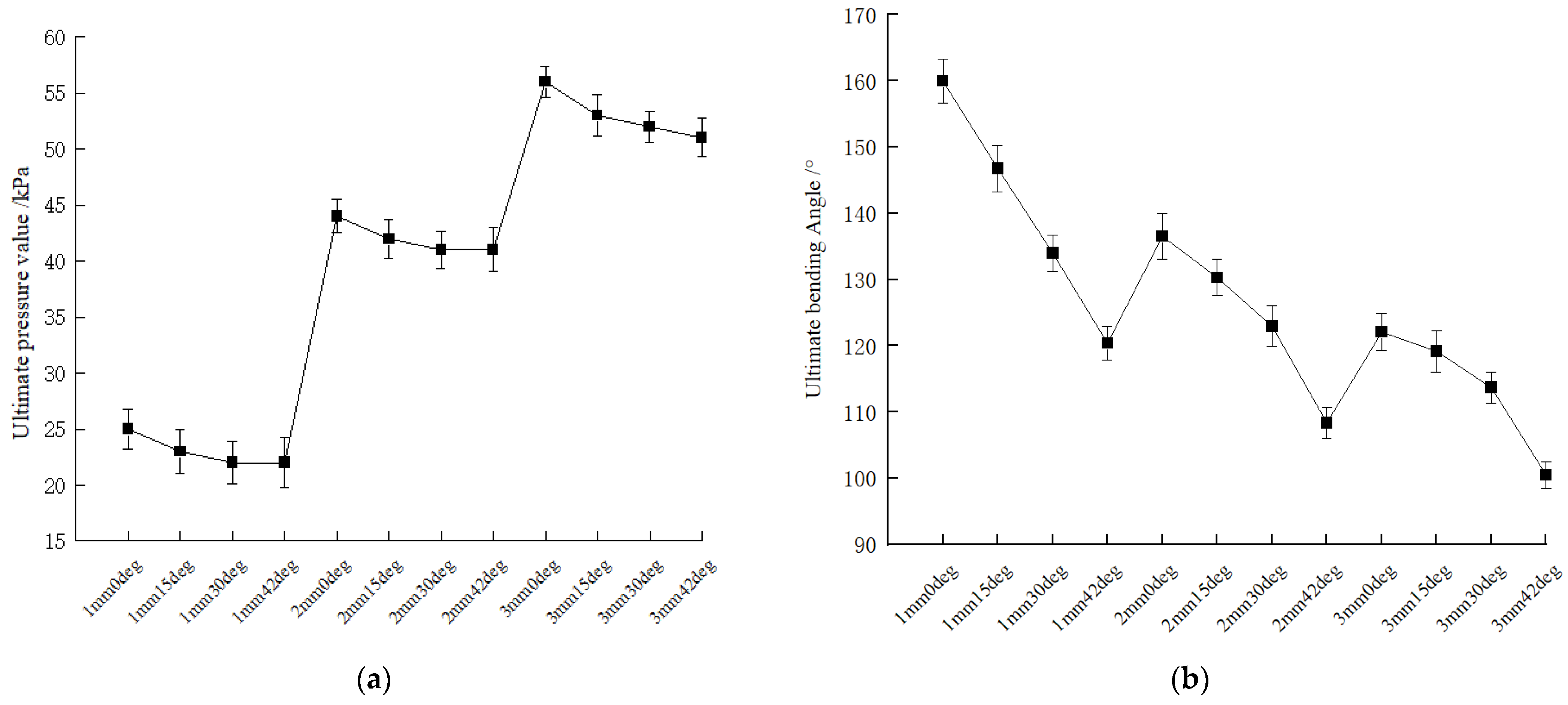
Flexible fingers will bend and deform after inflation, so the limit bending angle is also to be obtained in advance. It should be noted that the bending angle of the limit pressure value of the flexible finger cannot be simply used as the limit bending angle. In order to obtain the correct limit bending angle, similarly to the method used for testing the limit pressure, it was necessary to obtain the limit bending angle of 12 groups of different structural parameters, and also to take the average value of the limit bending angle of the five flexible fingers with the same structural parameters as the limit bending angle of the flexible fingers with these structural parameters. The error between the experimental value and the average value was about 3° or less. The ultimate pressure values and ultimate bending angles of the flexible fingers with 12 groups of different structural parameters obtained by the experiment are shown in Figure 12.

3.2.3. Bending Angle Test Experiment

In this paper, the ultimate pressure and bending angle of flexible fingers have been preliminarily tested. On this basis, the relationship between the pressure and bending angle of the flexible fingers needs to be further explored. The bending angle is one of the important performance indexes to measure the bending deformation degree of the flexible fingers. When the internal air pressure is unchanged, the larger bending angle of the flexible fingers proves a better bending deformation degree, which also proves the better envelope, adaptability, and flexibility of the flexible fingers. In this paper, the flexural angle of the flexible finger was tested by using the built flexible finger pressure stabilizing experimental platform, the bending deformation of the flexible finger was obtained under actual conditions, and the authenticity of the finite element analysis was verified to a certain extent. The silicone material selected has a soft texture and good rebound characteristics, with high elasticity. High elasticity means low hysteresis [32], so, in order to simplify the experimental model, this paper approximates that it has no large hysteresis.
In this paper, the bending angle of the flexible finger was obtained by using graph paper and a camera. The details are as follows. The camera was placed in the direction perpendicular to the coordinate paper, the obtained photo was imported into the angle measurement software, and the bending angle of the flexible finger was calculated.
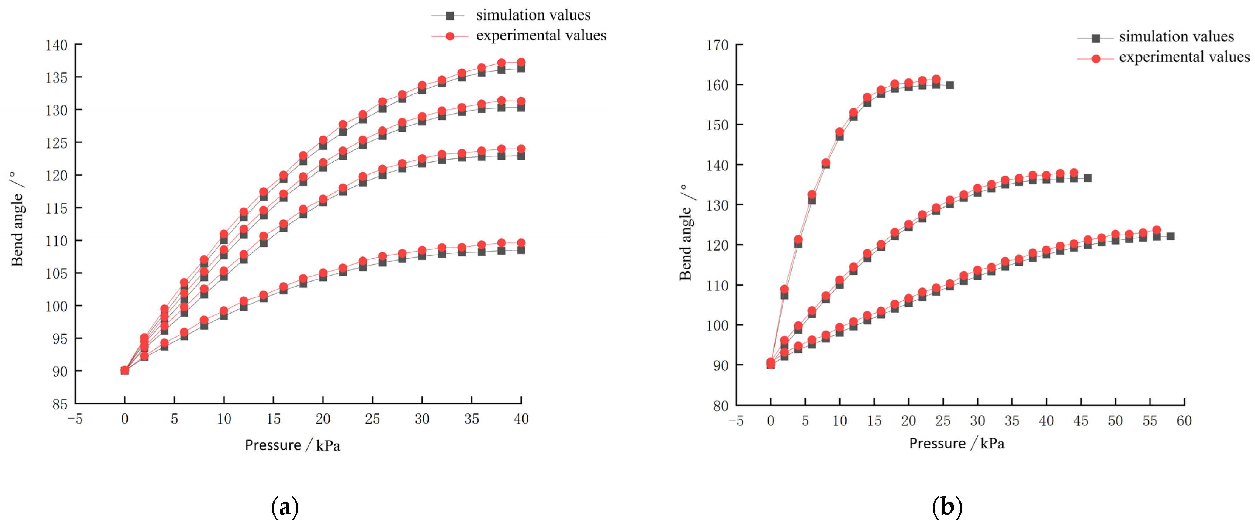
Consistent with the simulation, this paper took a flexible finger with a thickness of 2 mm as an example, and set the angle of the air cavity into four groups, which were 0 deg, 15 deg, 30 deg, and 42 deg, respectively. In order to ensure the authenticity and accuracy of the experiment, five flexible fingers with the same structural parameters were used in each group for five repeated experiments. Then, the average value of the five sets of data was taken as the experimental data of this group, and the experimental value was compared with the simulation value. Taking the flexible finger with an air cavity angle of 0 deg as an example, the thickness was set to three groups of 1 mm, 2 mm and 3 mm, and the average value of the five experiments was also taken as the experimental value. The comparison between the experimental value and the simulation value is shown in Figure 13.
As shown in Figure 13, the bending angle of the flexible finger increased with the increase in internal air pressure; under the same internal air pressure, the bending angle of the flexible finger decreased with the increase in the angle of the air cavity, and the rate of decrease increased with the increase in the angle of the air cavity. Differently from the effect of the air cavity angle on the finger bending angle, the bending angle of the flexible finger decreased with the increase in the thickness of the finger, and the reduction rate decreased with the increase in the thickness. These conclusions are consistent with the simulation analysis. Through analysis, it was found that there was a certain error between the experimental value of the bending angle of the flexible finger and the simulated value, and the actual value was slightly higher than the simulation value under the same internal air pressure. The maximum error reached 3%, which may have been caused by certain errors in the manufacturing process of flexible fingers. The accuracy of components such as pressure sensors and micro-air pumps will also have a certain impact, and the actual flexible fingers will also be affected by air resistance and other friction when bending. However, the overall trend of the experimental results was consistent with the simulation results, and the effectiveness of the simulation analysis was proved by the experiment. Both the experimental results and the simulation results provide support for the research of this paper.

3.2.4. Contact Force Test

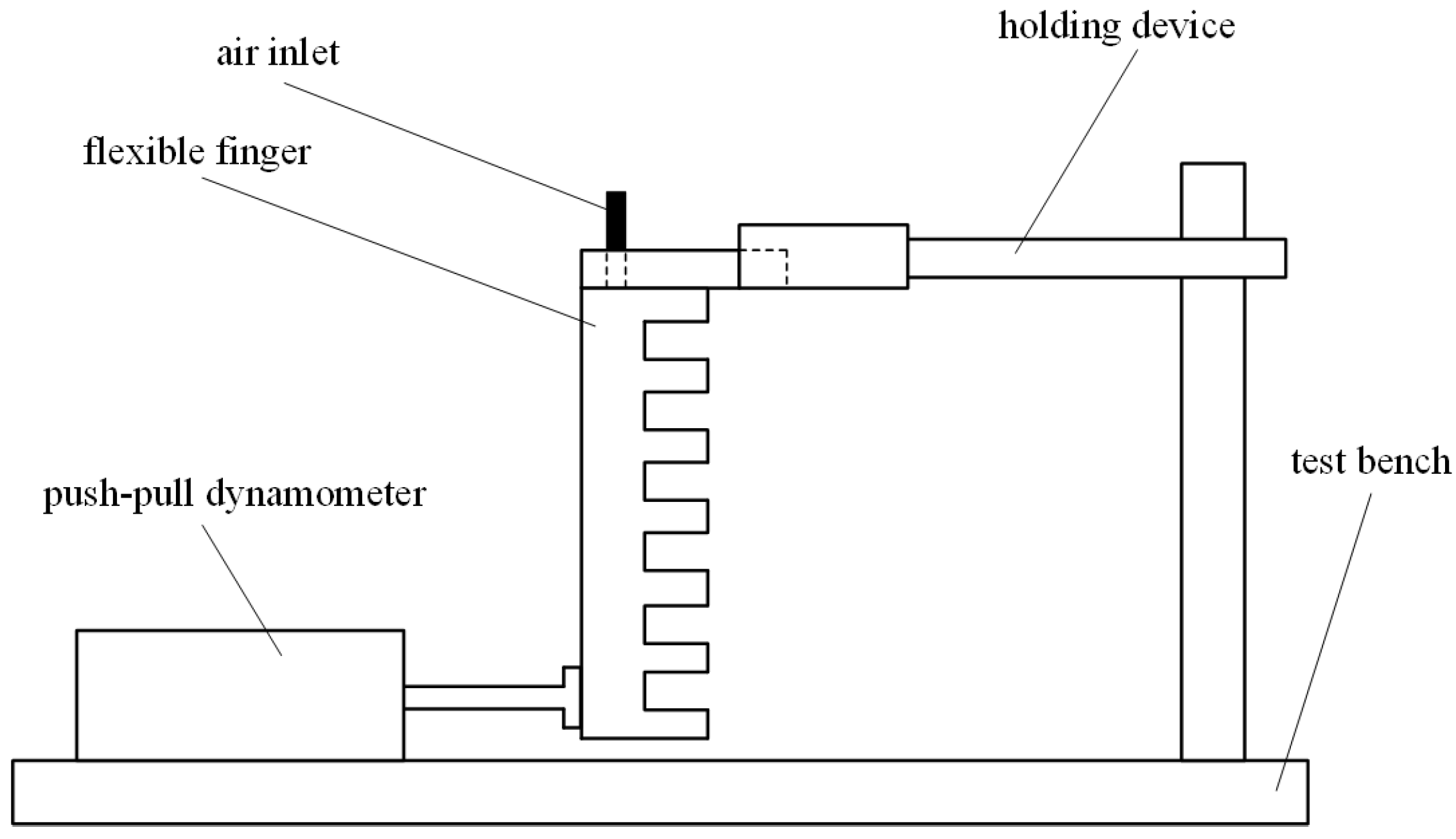
For the measurement of the grasping performance of the flexible gripper, in addition to the bending performance, the end contact force of the flexible finger is also very important. The end contact force can directly reflect the pressure of the flexible finger on the surface of the object: too large a contact force may damage the surface of the object, but too small a force makes it difficult to have a good clamping effect. It is very necessary to study the end contact force generated by the inflating deformation of the flexible finger, and the experimental device is shown in Figure 14.
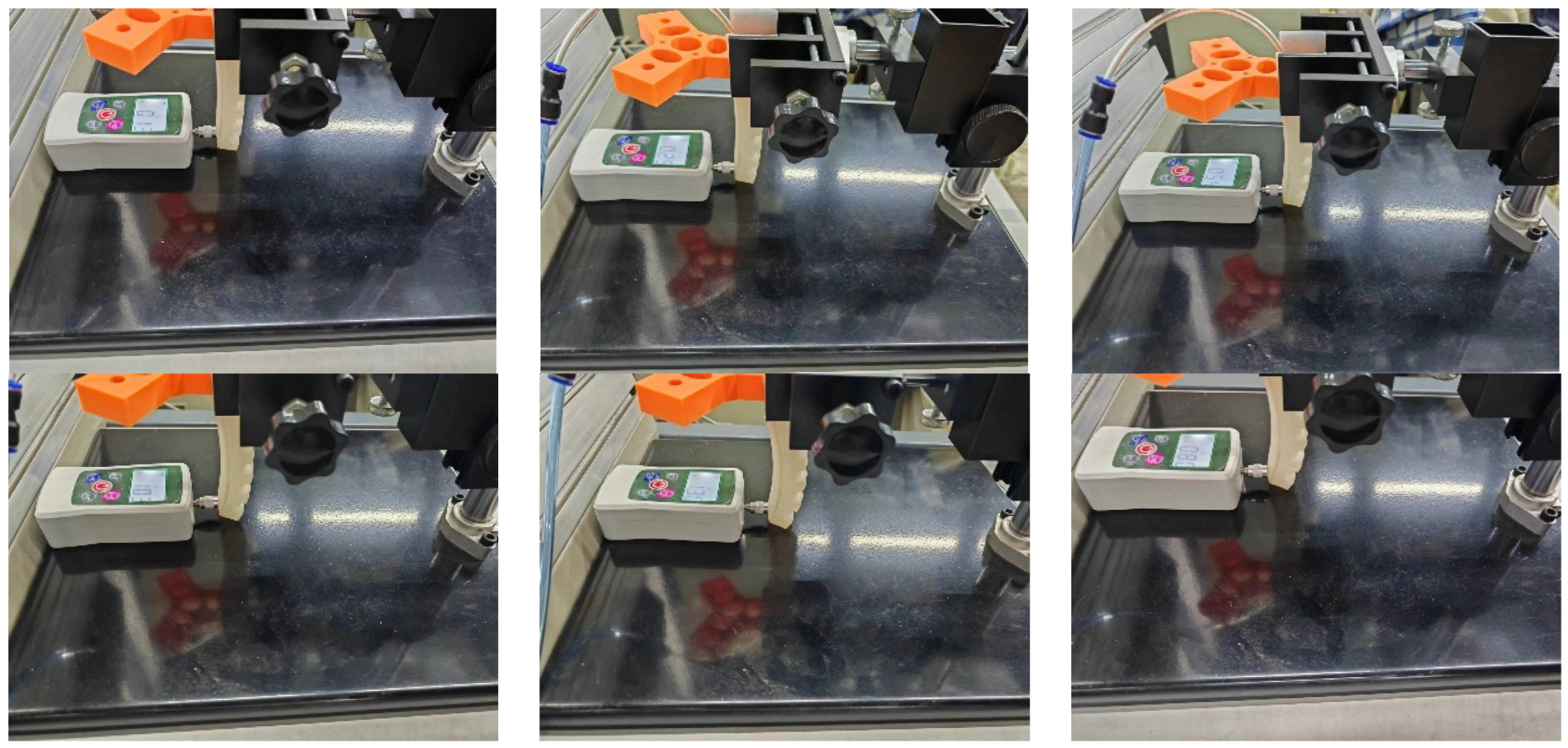
Consistent with an actual grasping situation, the finger end was clamped and fixed using a clamping device, and the end was kept in a free vertical state and in contact with the push–pull force gauge fixed on the experimental platform. When the finger was not inflated, the push–pull force gauge reading was 0 N. Taking a 2 mm thick flexible finger with an air chamber angle of 0 deg as an example, the finger was inflated internally through the trachea, with a pressure range of 0–44 kPa and an inflation interval of 2 kPa. Each inflation was repeated five times, and the experimental results are shown in Figure 15 and Figure 16. The experimental results show that there was an approximate linear relationship between the end contact force of a flexible finger and the internal input air pressure. When the internal input air pressure reaches 44 kPa, the maximum end contact force of a 2 mm thick flexible finger reaches 1.32 N, and the end contact force is inversely correlated with the angle of the air chamber.

4. Control Algorithm Analysis

4.1. Flexible Finger Pressure Control Algorithm Based on RBF Neural Network Tuning PID Control

The bending angle test of the flexible finger and the end contact force test both need to realize the pressure regulation of the internal gas, and it is very necessary to control the pressure output of the micro-air pump. The traditional pressure regulation control usually adopts a PID control strategy, which is simple in structure and convenient to use, and has strong adaptability and robustness.
The artificial neural network is also known as the neural network. In 1943, scholars such as W. Mcculloch and W. Pitts proposed the mathematical model of neurons [33]. On this basis, Powell proposed the radial basis function (RBF). In 1988, Broomhead and Lowe first applied the RBF to neural networks [34,35].
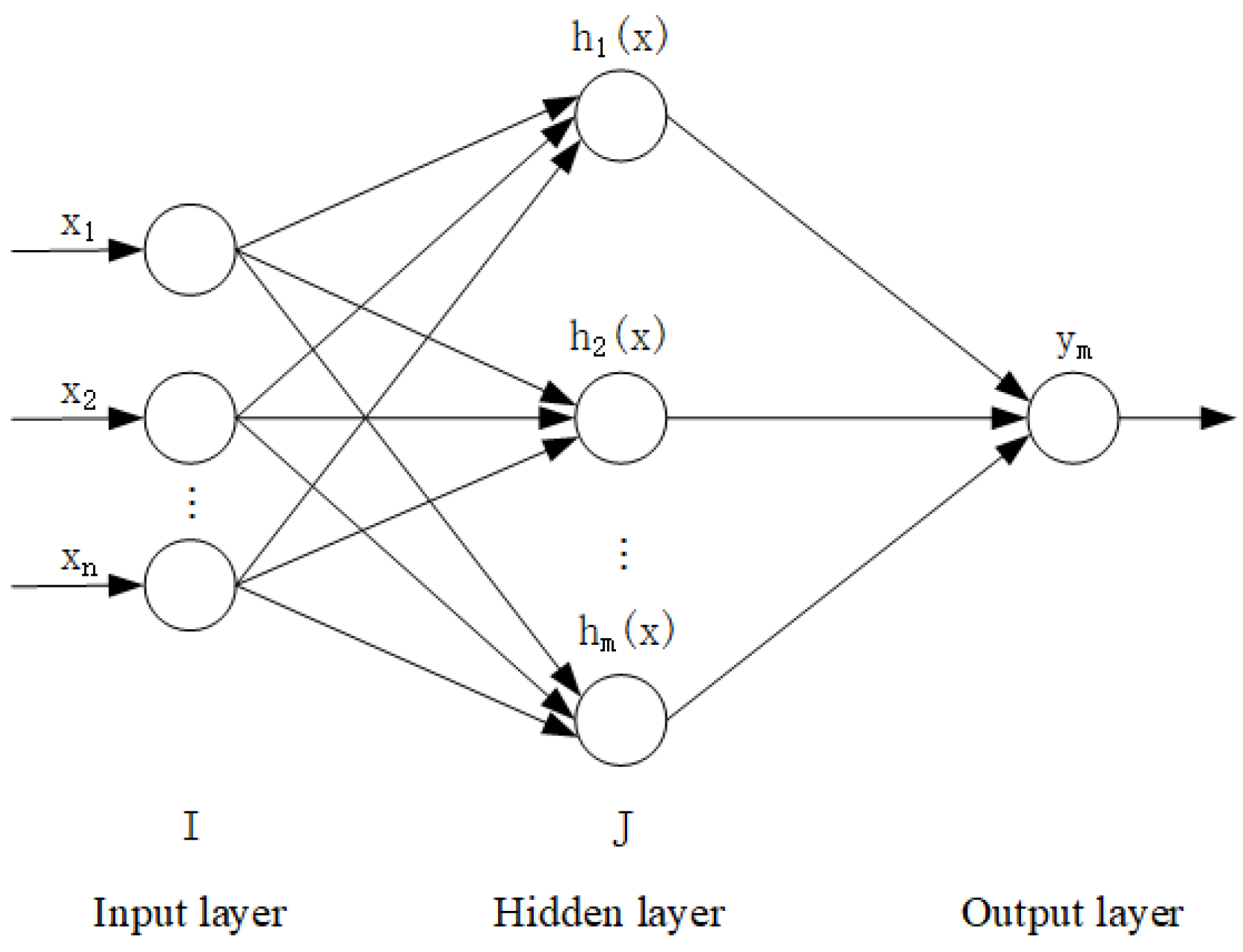
The control structure of the RBF neural network consists of the input layer, hidden layer, and output layer. The signal source nodes constitute the input layer and connect the external environment with the neural network. The number of nodes in the hidden layer and the output layer is determined by the research object. The structure of the RBF neural network is shown in Figure 17.
As shown in Figure 17, the structure type of the RBF neural network is n-m-1. The input layer is X = x 1 , x 2 , . . . x n , the weight from the hidden layer to the output layer can be set to W = w 1 , w 2 , . . . w j T , assuming the radial basis vector is h j , and the output of the neural network is represented by y m .
The RBF neural network has two mappings.
One is the nonlinear mapping from the input layer to the hidden layer. Specifically, the input layer N-dimensional data are mapped to the M-dimensional space of the hidden layer, and the mapping from X to h j is realized. The mathematical expression of the radial basis vector is as follows:
h j = f j ( x 1 , x 2 , x n )
where f j represents the radial basis function, j = 1,2 , 3 , . . . m .
The second is the linear mapping from the hidden layer to the output layer. Specifically, the M-dimensional space vector of the hidden layer is summed and calculated by linear weighting, and then passed to the output layer for output. To realize the mapping of h j to y m , its mathematical expression is:
y m = j m w j h j
The specific principle of the RBF neural network is to calculate the neural response of certain data in the N-dimensional space, and the neural response will occur in the neurons in the hidden layer, so the essence of the output of the neural network is the weighted sum of the neuronal response.
Because the Gaussian function has a simple structure, good symmetry, and smoothness, in this paper, the Gaussian-type function is selected as the radial basis function, as shown in the following formula:
f X = e x p ( X c j i 2 b j 2 ) , b j > 0 , x R
where c j i represents the central point of the JTH hidden layer neuron, c j i = c j 1 , , c j n . b is the width vector of the Gaussian function, and b = b 1 , , b m T .
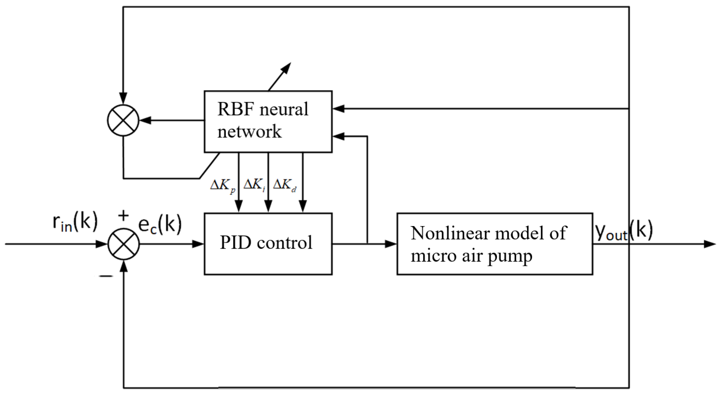
Because the micro-air pump studied in this paper has strong nonlinear characteristics, the RBF neural network is combined with the traditional PID control strategy, and the RBF neural network is used to adjust the PID parameters, so as to achieve more accurate control effect. The micro-air pump control system with the RBF network tuning the PID parameters is shown in Figure 18.
r i n in Figure 18 represents the given control signal, and y o u t represents the output pressure signal of the micro-air pump. The input of the PID control is error signal e c ( k ) , the input of the RBF neural network is the output of the micro-air pump pressure signal and PID control, and its output is the compensation of the PID control parameters. The output of the PID control can be optimized by the self-learning ability of the RBF neural network.
The error e c ( k ) is:
e c ( k ) = r in ( k ) y out ( k )
x c 1 ( k ) = e ( k ) e ( k 1 )
x c 2 ( k ) = e ( k )
x c 3 ( k ) = e ( k ) 2 e ( k 1 ) + e ( k 2 )
This paper uses incremental PID control, and its mathematical formula is as follows:
u ( k 1 ) = K p e ( k 1 ) + K i j = 0 k 1 e ( j ) + K d e ( k 1 ) e ( k 1 )
Δ u ( k ) = K p x c 1 ( k ) + K i x c 2 ( k ) + K d x c 3 ( k )
The control law is as follows:
u ( k ) = u ( k 1 ) + Δ u ( k )
The training index of the RBF neural network is:
E c ( k ) = 1 2 e c ( k ) 2
In this paper, the gradient descent method is used to adjust the PID parameters as follows:
Δ K p ( k ) = η c E c ( k ) E p ( k 1 ) = η c e c ( k ) y out ( k ) u ( k ) x c 1 ( k )
Δ K i ( k ) = η c E c ( k ) E j ( k 1 ) = η c e c ( k ) y out ( k ) u ( k ) x c 2 ( k )
Δ K d ( k ) = η c E c ( k ) E d ( k 1 ) = η c e c ( k ) y out ( k ) u ( k ) x c 3 ( k )
The PID parameter learning rules are as follows:
K p ( k ) = K p ( k 1 ) + Δ K p ( k ) + α c K p ( k 1 ) K p ( k 2 )
K i ( k ) = K i ( k 1 ) + Δ K i ( k ) + α c K i ( k 1 ) K i ( k 2 )
K d ( k ) = K d ( k 1 ) + Δ K d ( k ) + α c K d ( k 1 ) K d ( k 2 )
In the formula, η c is the learning efficiency of k ( p ) , k ( i ) , and k ( d ) , respectively, y o u t ( k ) u ( k ) represents the sensitivity of the output of the micro-air pump to the control (Jacobian information), and the expression is:
y o u t ( k ) u ( k ) y m ( k ) u ( k ) = j = 1 m w j ( k 1 ) h j ( x ( k ) ) u ( k ) = j = 1 m w j ( k 1 ) h j ( x ( k ) ) c j ( n y + 1 ) ( k 1 ) u ( k ) b j 2 ( k 1 )
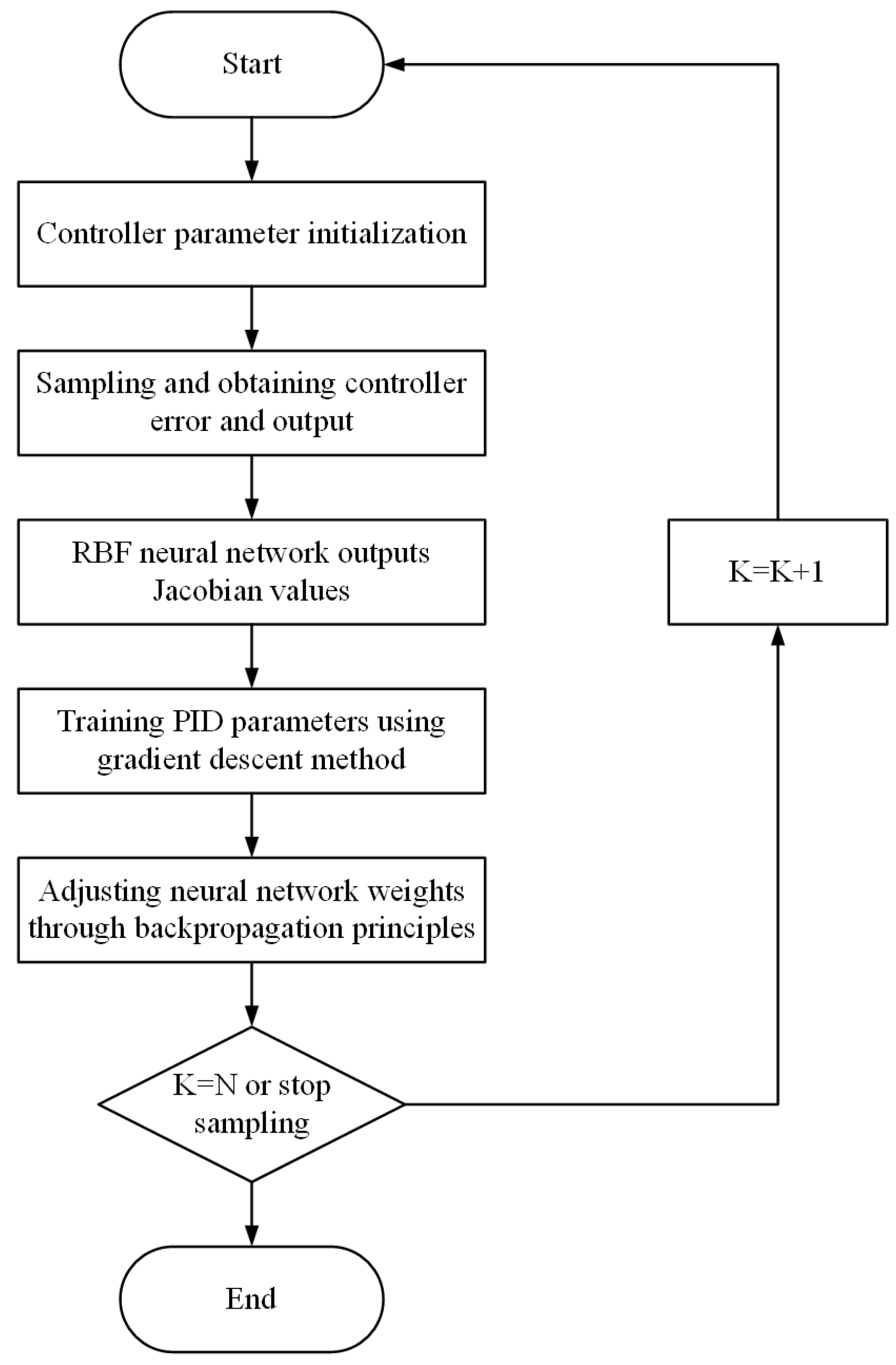
The flow chart of the PID control strategy with tuning by the RBF neural network is shown in Figure 19.

4.2. Flexible Finger Pressure Control Experiment Based on RBF Neural Network Tuning PID Control

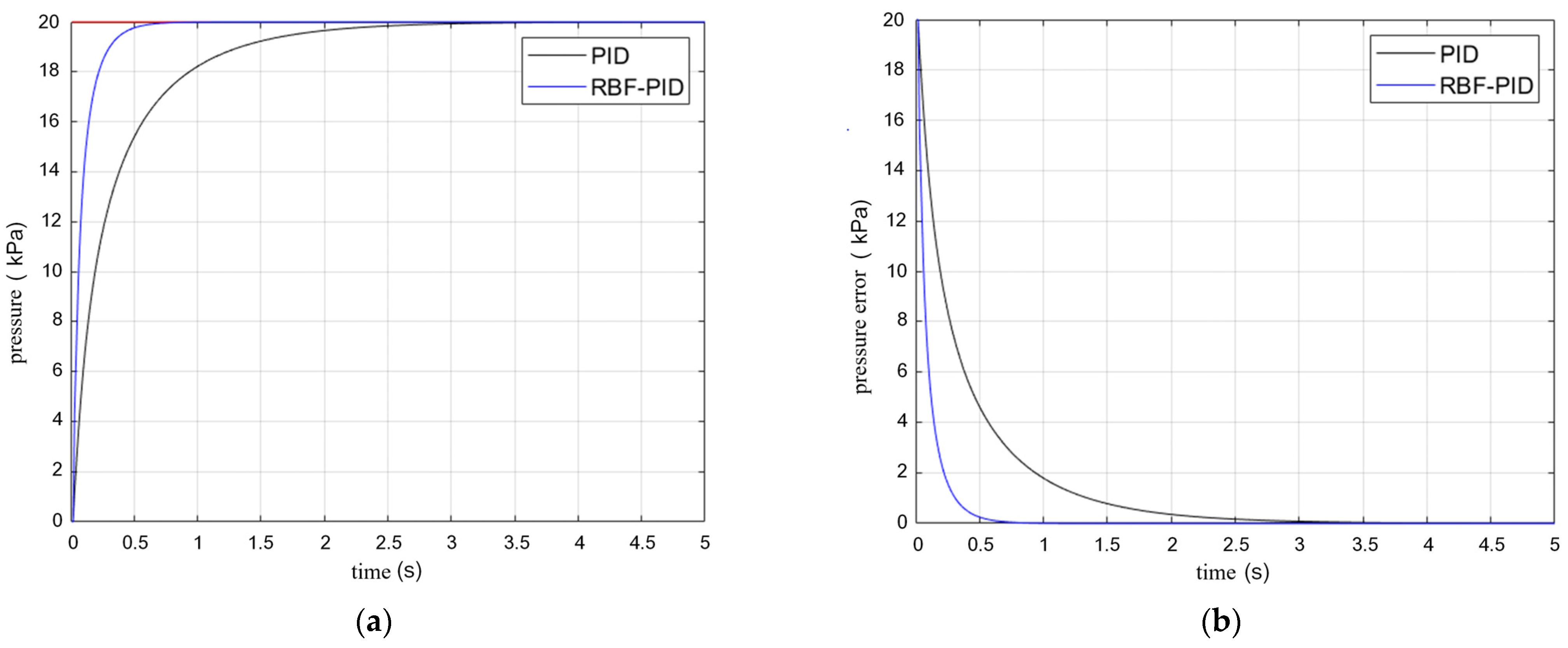
The pressure signal of the flexible finger was set as a step signal, and a 20 kPa system input was given at the target position. The pressure stabilizing control effect is shown in Figure 20.
As can be seen from Figure 20, when the finger input pressure was set to 20 kPa, the response time taken by the traditional PID control system to reach the stable state was 3.23 s, and the response time of the RBF-PID control system was 0.78 s, without overshoot. Compared with the traditional PID control system, the RBF-PID control system improves the response speed, and its control effect is better than the traditional PID control system.

5. Conclusions

(1) This article explores the emerging flexible gripper mechanism and conducts structural analysis and design of the key parts of the flexible finger. From a manufacturing perspective, the production of molds and methods for making flexible fingers are discussed, and a physical model is made to provide a basis for subsequent experimental analysis.
(2) We measured the material parameters of the standard sample, simulate the bending of the flexible fingers under different structural parameters using Abaqus simulation software, and preliminarily explored the effects of the flexible finger air chamber angle and finger thickness on the finger bending performance.
(3) We built a flexible finger stabilization experimental platform, conducted pre-inflation experiments on the flexible fingers, and preliminarily analyzed the ultimate pressure and ultimate bending angle of the flexible fingers under actual conditions. The simulation analysis was experimentally verified through the established voltage stabilization experimental platform, and the experimental error was within a reasonable range. The relationship between the finger structural parameters and end contact force was explored.
(4) In order to optimize the inflation and stabilization process of the flexible fingers, enhance the gripping ability of subsequent flexible gripper mechanisms, improve gripping efficiency, and reduce energy consumption, this paper proposed a flexible finger stabilization control algorithm based on an RBF neural network tuning a PID control. By adjusting the output duty cycle of the nonlinear model of the micro-air pump, stabilization control of the flexible fingers was achieved. Finally, step signal testing was conducted, and the results show that the RBF-PID control algorithm is superior to traditional PID control algorithms.

Author Contributions

Conceptualization, Y.Z. and K.W.; methodology, Y.Z. and K.W.; software, K.W.; validation, M.C. and Y.S.; formal analysis, S.G.; investigation, K.W.; resources, M.C. and Y.S.; data curation, S.G. and H.Z.; writing—original draft preparation, K.W. and P.Z.; writing—review and editing, K.W. and P.Z.; visualization, P.Z.; supervision, M.C. and Y.S.; project administration, Y.Z. and H.Z.; funding acquisition, Y.Z. All authors have read and agreed to the published version of the manuscript.

Funding

This research was funded by the Outstanding Young Scientists in Beijing (Grant No. BJJWZYJH01201910006021), the Key Scientific and Technological Project of Henan Province (Grant No. 202102210081) and Doctoral Funded Programs Supported by Henan Polytechnic University (Grant No. B2021-29).

Data Availability Statement

Data are contained within the article.

Conflicts of Interest

Author Hui Zhang was employed by the company Pingyuan Filter Co., Ltd. The remaining authors declare that the research was conducted in the absence of any commercial or financial relationships that could be construed as a potential conflict of interest.

References

  1. Li, B. Research on the Design of Manipulator Robot Claw. Mod. Ind. Econ. Inf. Technol. 2020, 10, 41–42. [Google Scholar]
  2. Tuleja, P.; Sidlovska, L. Unilateral gripping with active vacuum suction cup Calculation of gripping force and number of suction cups. Transf. Inovacii 2014, 29, 232–235. [Google Scholar]
  3. Shintake, J.; Cacucciolo, V.; Floreano, D.; Shea, H. Soft robotic grippers. Adv. Mater. 2018, 30, 1707035. [Google Scholar] [CrossRef] [PubMed]
  4. Rus, D.; Tolley, M.T. Design, fabrication and control of soft robots. Nature 2015, 521, 467–475. [Google Scholar] [CrossRef] [PubMed]
  5. Tramacere, F.; Beccai, L.; Mattioli, F.; Sinibaldi, E.; Mazzolai, B. Artificial Adhesion Mechanisms Inspired by Octopus Suckers. In Proceedings of the 2012 IEEE International Conference on Robotics and Automation, Saint Paul, MN, USA, 14–18 May 2012; IEEE: Piscataway, NJ, USA, 2018; pp. 3846–3851. [Google Scholar]
  6. Zheng, Z.; Wang, K.; Wu, X.; Zhang, Q.; Li, K. Dynamic analysis of elastic projecting robot inspired by chameleon tongue. In Proceedings of the 2018 IEEE International Conference on Robotics and Biomimetics (ROBIO), Kuala Lumpur, Malaysia, 12–15 December 2018; IEEE: Piscataway, NJ, USA, 2018; pp. 2088–2094. [Google Scholar]
  7. Zhang, Z.; Zhou, J.; Yi, B.; Wang, K. A flexible swallowing gripper for harvesting apples and its grasping force sensing model. Comput. Electron. Agric. 2023, 204, 107489. [Google Scholar] [CrossRef]
  8. Luo, Z.; Wang, S.; Cheng, G.; Yuan, N.; Ding, J. Design, manufacturing, and control of biomimetic hands based on elastic materials. J. Mech. Eng. 2019, 55, 11. [Google Scholar] [CrossRef]
  9. Barbieri, L.; Bruno, F.; Gallo, A.; Muzzupappa, M.; Russo, M.L. Design, Prototyping and Testing of a Modular Small-Sized Underwater Robotic Arm Controlled through a Master-Slave Approach. Ocean. Eng. 2018, 158, 253–262. [Google Scholar] [CrossRef]
  10. Hao, Y.; Gong, Z.; Xie, Z.; Guan, S.; Yang, X.; Ren, Z.; Wang, T.; Wen, L. Universal soft pneumatic robotic gripper with variable effective length. In Proceedings of the 2016 35th Chinese control conference (CCC), Chengdu, China, 27–29 July 2016; IEEE: Piscataway, NJ, USA, 2018; pp. 6109–6114. [Google Scholar]
  11. Sinatra, N.R.; Teeple, C.B.; Vogt, D.M.; Parker, K.K.; Gruber, D.F.; Wood, R.J. Ultragentle Manipulation of Delicate Structures Using a Soft Robotic Gripper. Sci. Robot 2019, 4, 5425. [Google Scholar] [CrossRef] [PubMed]
  12. Lau, G.K.; Heng, K.R.; Ahmed, A.S.; Shrestha, M. Dielectric elastomer fingers for versatile grasping and nimble pinching. Appl. Phys. Lett. 2017, 110, 18. [Google Scholar] [CrossRef]
  13. Li, L.; Fengming, X.; Tianhong, W.; Guopeng, W.; Yingzhong, T.; Tao, J.; Quan, Z. Stiffness-Tunable Soft Gripper with Soft-Rigid Hybrid Actuation for Versatile Manipulations. Soft Robot. 2022, 9, 1108–1119. [Google Scholar] [CrossRef]
  14. Homberg, B.S.; Katzschmann, R.K.; Dogar, M.R.; Rus, D. Haptic identification of objects using a modular soft robotic gripper. In Proceedings of the 2015 IEEE/RSJ International Conference on Intelligent Robots and Systems (IROS), Hamburg, Germany, 28 September–2 October 2015; IEEE: Piscataway, NJ, USA, 2015; pp. 1698–1705. [Google Scholar]
  15. Merces, L.; Ferro, L.M.M.; Thomas, A.; Karnaushenko, D.D.; Luo, Y.; Egunov, A.I.; Zhang, W.; Bandari, V.K.; Lee, Y.; McCaskill, J.S.; et al. Bio-Inspired Dynamically Morphing Microelectronics toward High-Density Energy Applications and Intelligent Biomedical Implants. Adv. Mater. 2024, 36, 2313327. [Google Scholar] [CrossRef] [PubMed]
  16. Zhu, Y.; Birla, M.; Oldham, K.R.; Filipov, E.T. Elastically and Plastically Foldable Electrothermal Micro-Origami for Controllable and Rapid Shape Morphing. Adv. Funct. Mater. 2020, 30, 2003741. [Google Scholar] [CrossRef]
  17. Tawk, C.; Gillett, A.; in het Panhuis, M.; Spinks, G.M.; Alici, G. A 3D-Printed Omni-Purpose Soft Gripper. IEEE Trans. Robot. 2019, 35, 1268–1275. [Google Scholar] [CrossRef]
  18. Xavier, M.S.; Tawk, C.D.; Zolfagharian, A.; Pinskier, J.; Howard, D.; Young, T.; Jiewen, L.; Harrison, S.M.; Yong, Y.K.; Bodaghi, M.; et al. Soft pneumatic actuators: A review of design, fabrication, modeling, sensing, control and applications. IEEE Access 2022, 10, 59442–59485. [Google Scholar] [CrossRef]
  19. Pagoli, A.; Chapelle, F.; Corrales-Ramon, J.A.; Mezouar, Y.; Lapusta, Y. Review of soft fluidic actuators: Classification and materials modeling analysis. Smart Mater. Struct. 2021, 31, 013001. [Google Scholar] [CrossRef]
  20. Marchese, A.D.; Katzschmann, R.K.; Rus, D. A recipe for soft fluidic elastomer robots. Soft Robot. 2015, 1, 7–25. [Google Scholar] [CrossRef] [PubMed]
  21. Hu, W.; Mutlu, R.; Li, W.; Alici, G. A structural optimisation method for a soft pneumatic actuator. Robotics 2018, 7, 24. [Google Scholar] [CrossRef]
  22. Xavier, M.S.; Fleming, A.J.; Yong, Y.K. Design and control of pneumatic systems for soft robotics: A simulation approach. IEEE Robot. Autom. Lett. 2021, 6, 5800–5807. [Google Scholar] [CrossRef]
  23. Joshi, S.; Paik, J. Pneumatic supply system parameter optimization for soft actuators. Soft Robot. 2021, 8, 152–163. [Google Scholar] [CrossRef]
  24. Joshi, S.; Sonar, H.; Paik, J. Flow path optimization for soft pneumatic actuators: Towards optimal performance and portability. IEEE Robot. Autom. Lett. 2021, 6, 7949–7956. [Google Scholar] [CrossRef]
  25. Qian, P.; Luo, H.; Liu, L.; Lv, P.; Pu, C.; Meng, D.; Páez, L.M.R. A hybrid Gaussian mutation PSO with search space reduction and its application to intelligent selection of piston seal grooves for homemade pneumatic cylinders. Eng. Appl. Artif. Intell. 2023, 122, 106156. [Google Scholar] [CrossRef]
  26. Qian, P.; Liu, L.; Wu, J.; Pu, C.; Luo, H.; Fu, Y.; Zuo, Q. A novel double-acting, air-floating, frictionless pneumatic actuator. Sens. Actuators A Phys. 2023, 362, 114674. [Google Scholar] [CrossRef]
  27. Shi, Y.; Li, H.; Fu, X.; Luan, R.; Wang, Y.; Wang, N.; Wang, N.; Sun, Z.; Niu, Y.; Wang, C.; et al. Self-powered difunctional sensors based on sliding contact-electrification and tribovoltaic effects for pneumatic monitoring and controlling. Nano Energy 2023, 110, 108339. [Google Scholar] [CrossRef]
  28. Shi, Y.; Yang, Z.; Wang, Y.; Xu, S.; Sun, Z.; Wu, J.; Wang, C. Observer-Based Adaptive Finite-Time Contact Force Tracking Control for Pneumatic Polishing System. IEEE Sens. J. 2024, 24, 19801–19812. [Google Scholar] [CrossRef]
  29. Wang, C.; Shi, Y.; Wang, Y.; Xu, S.; Liang, M. Event-Triggered Adaptive Fuzzy Output Feedback Tracking Control for Pneumatic Servo System with Input Voltage Saturation and Position Constraint. IEEE Trans. Ind. Inform. 2024, 20, 4360–4369. [Google Scholar] [CrossRef]
  30. Wang, C.; Shi, Y.; Wang, Y.; Xu, S.; Sun, Z. Position Tracking Control for Pneumatic Servo System Subject to State Constraints and Voltage Saturation. IEEE/ASME Trans. Mechatron. 2023, 43, 1–11. [Google Scholar] [CrossRef]
  31. Wang, N.; Xu, L.; Xie, F.; Shi, Y.; Wang, Y. Research on the dynamic characteristics of pneumatic proportional regulator in pneumatic-loading system and design of fuzzy adaptive controller. Sci. China Technol. Sci. 2022, 65, 956–965. [Google Scholar] [CrossRef]
  32. Halladay, J.R.; Jaglowski, K.T. Sources of hysteresis in rubber compound. Rubber Plast. News 2017, 7, 13–17. [Google Scholar]
  33. McCulloch, A. Logival of the ideas imminent in nervous activity. Bull. Math. Biophys. 1943, 5, 115–133. [Google Scholar] [CrossRef]
  34. Powell, M.J.; Radial, D. Basis Function for Multivariable Interpolation: A Review; Mason, J.C., Cox, M.G., Eds.; Algorithms for Approximation; Carendon Press: Oxford, UK, 1985; pp. 143–167. [Google Scholar]
  35. Broomhead, D.S.; Lowe, D. Multivariable functional interpolation and adaptive networks. Complex Syst. 1998, 2, 321–355. [Google Scholar]
Figure 1. The overall structure of the flexible finger.
Actuators 13 00271 g001
Figure 2. Pouring process.
Actuators 13 00271 g002
Figure 3. Single flexible finger manufacturing process.
Actuators 13 00271 g003
Figure 4. The physical objects of fingers and molds: (a) Upper mold printed using PLA material; (b) Inner mold printed using TPU material; (c) Lower mold printed using TPU material; (d) Soft finger thin edge.
Actuators 13 00271 g004
Figure 5. Preparation of dumbbell-shaped silicone samples by wax casting method and conducting tensile tests: (a) Dumbbell sample size parameters; (b) Wax tank sample; (c) Dumbbell-shaped silicone sample; (d) Force displacement curve of dumbbell-shaped silicone sample.
Actuators 13 00271 g005
Figure 6. The results of Yeoh model fitting.
Actuators 13 00271 g006
Figure 7. Thickness 2 mm air chamber angle 0 deg flexible finger inflation simulation: (a) Bending of the flexible finger when the pressure value is 5 kPa; (b) Bending of the flexible finger when the pressure value is 10 kPa; (c) Bending of the flexible finger when the pressure value is 15 kPa; (d) Bending of the flexible finger when the pressure value is 20 kPa; (e) Bending of the flexible finger when the pressure value is 25 kPa; (f) Bending of the flexible finger when the pressure value is 30 kPa; (g) Bending of the flexible finger when the pressure value is 35 kPa; (h) Bending of the flexible finger when the pressure value is 40 kPa.
Actuators 13 00271 g007
Figure 8. The relationship between the angle of the air cavity and the bending property of a 2 mm thick flexible finger.
Actuators 13 00271 g008
Figure 9. Relation between finger thickness and bending property of 0 deg air cavity angle flexible finger.
Actuators 13 00271 g009
Figure 10. Schematic diagram of the experimental platform.
Actuators 13 00271 g010
Figure 11. Physical diagram of the experimental platform: (a) Overall schematic diagram of the experimental platform; (b) Pneumatic control circuit.
Actuators 13 00271 g011
Figure 12. (a) Ultimate pressure values of flexible fingers with twelve different structural parameters; (b) Ultimate bending angle values of flexible fingers with twelve different structural parameters.
Actuators 13 00271 g012
Figure 13. (a) Comparison between experimental and simulated values of 2 mm thick flexible fingers; (b) Comparison between experimental and simulated values of the flexible finger with an air chamber angle of 0 deg.
Actuators 13 00271 g013
Figure 14. Experimental principle of contact force at the end of flexible fingers.
Actuators 13 00271 g014
Figure 15. The testing process of contact force at the end of flexible fingers.
Actuators 13 00271 g015
Figure 16. Test results of contact force at the end of a 2 mm thick flexible finger.
Actuators 13 00271 g016
Figure 17. Structure of RBF neural network.
Actuators 13 00271 g017
Figure 18. Micro-air pump control system with RBF network tuning PID parameters.
Actuators 13 00271 g018
Figure 19. Process of RBF neural network tuning PID control strategy.
Actuators 13 00271 g019
Figure 20. Step response curve of RBF neural network tuning PID: (a) Pressure curve; (b) Pressure error curve.
Actuators 13 00271 g020
Table 1. Experimental equipment parameters.
Device NameDevice TypeInput VoltageOutput VoltageInput Air PressureOutput Air Pressure
power supply AD-30B100–240 V5–24 V//
power supply BS-35-12115–230 V12 V//
terminal boardCB-68LP////
breadboardZY-60////
data acquisition cardPCI-E 6353−10–10 V−10–10 V//
driver moduleL298N9–12 V0–12 V//
air pressure sensorXGZP6847A/0.5–4.5 V−100–700 kPa/
micro-air pump370-B0–12 V//−60–160 kPa
two-way ball valveVHK2-06F-06F////
barometerYN60//0–100 kPa/
gas-stabilizing device/////
holding devicesyj-02////
measuring paperA4////
computer/////
Disclaimer/Publisher’s Note: The statements, opinions and data contained in all publications are solely those of the individual author(s) and contributor(s) and not of MDPI and/or the editor(s). MDPI and/or the editor(s) disclaim responsibility for any injury to people or property resulting from any ideas, methods, instructions or products referred to in the content.