Article

A Steady-Pressure Control Method for Emulsion Pump Station Based on Online Updating of Optimal Flow Rate

by
Peng Xu
1,2,
Ziming Kou
1,2,*,
Juan Wu
1,2,
Tengyan Hou
1,2,
Yanwei Peng
1,2 and
Buwen Zhang
1,2
1
College of Mechanical and Vehicle Engineering, Taiyuan University of Technology, Taiyuan 030024, China
2
National and Local Joint Engineering Laboratory for Mining Fluid Control, Taiyuan 030024, China
*
Author to whom correspondence should be addressed.
Actuators 2024, 13(7), 247; https://doi.org/10.3390/act13070247
Submission received: 16 May 2024 / Revised: 20 June 2024 / Accepted: 25 June 2024 / Published: 28 June 2024

Abstract

:
In order to solve the problem of unstable fluid supply pressure and serious impact caused by the complicated and changeable working condition of a fully mechanized mining face in coal mines and the sluggish response of the fluid supply system to the fluid demand for the hydraulic support, a control method based on online updating generalized regression neural network (GRNN) was proposed. Firstly, the simulated hydraulic support test platform and co-simulation model were built. Secondly, The optimal flow dataset of steady-pressure fluid supply under different working conditions is calculated by simulation. Furthermore, the GRNN prediction model was established by using dataset and online updating learning technology to predict the optimal fluid supply flow according to environmental parameters. Finally, the optimal flow control method of online updating GRNN was established, and numerical research and experimental verification were also carried out in different working conditions. The results indicated that the proposed control method could track the working conditions of the working face in real time and adjusted the fluid supply flow of the emulsion pump station adaptively, which effectively alleviated the pressure fluctuation and pressure shock, and the system pressure was more stable, meeting the demand of steady-pressure fluid supply on the working face.

1. Introduction

The construction of intelligent mines in China is developing at a high speed. In order to meet the accelerating mining speed of the working face, higher requirements are put forward for the reliability and stability of intelligent mining of the fully mechanized working face [1,2]. As the power source of hydraulic support in a fully mechanized mining face, the emulsion pump station directly affects the working efficiency and stability of hydraulic support, which is the key equipment to ensure the safety and high efficiency of coal mine production [3,4]. Due to the coupling relationship between the operating speed, action type, working resistance, fluid supply flow and system pressure of the hydraulic support system [5], the pressure-transient characteristics of the hydraulic support system are obvious. Meanwhile, with the increase in working resistance of the hydraulic support at large mining height and the increase in working face length, the problem of poor stability of fluid supply pressure becomes more obvious. Therefore, how to improve the stability of the fluid supply system as much as possible under different working conditions of hydraulic support is an important and complicated problem to be solved urgently in the fluid supply control of an emulsion pump station.
Improving the stability of the fluid supply system is the key to safe and efficient production of coal face. At present, scholars mainly strive to maintain the stable pressure of the system through two aspects: one is to optimize the structure of the hydraulic system to reduce the pressure fluctuation, and the other is to improve the fluid supply quality of the emulsion pump station by the intelligent control algorithm. Among them, there were many studies on optimizing the structure of hydraulic systems by scholars: the system pressure was stabilized by optimizing the accumulator parameters and the accumulator configuration scheme [6,7]; the transient dynamic characteristics of pipelines were improved by optimization of pipeline size parameters [8,9]; the layout of the emulsion pump station and pipeline layout were improved to reduce pressure loss [10,11]; the unloading valve was reasonably utilized to recover pressure to ensure the stability of the emulsion pumping station [12]. and other methods. However, optimizing the structure of the hydraulic system can reduce the pressure loss and pressure shock, but it can only play an auxiliary role in the problem of pressure stability in the system with long-distance fluid supply and strong time-varying load.
In order to make the operation of the equipment on the working surface more stable, the key to ensure the pressure stability of the hydraulic system is to adopt the appropriate intelligent control method to improve the fluid supply quality of the emulsion pump station. Tian et al. [13] studied the application of PLC variable frequency speed regulation and constant pressure technology in the mine emulsion pump. The experimental results showed that the design of the variable frequency–constant voltage control system based on PLC could effectively save energy consumption. T. Qiao et al. [14] applied the fuzzy control and PID control method to the variable frequency and constant pressure control system of a mine emulsion pump station, and obtained good dynamic performance. Tan et al. [15] trained field data based on Elman neural network, combined with movement time and pressure setting, and carried out pressure predictive control on an emulsion pump station. Wang and Li [16] optimized the variable frequency driving mode and adopted the control mode of combining frequency converter with combined switch to realize constant-pressure fluid supply in coal mining face. By predicting the traction speed of the shearer, the power demand of hydraulic support is predicted, and then the intelligent adjustment of pressure and flow of the shearer station is realized by using a mixed particle swarm optimization algorithm. Li [17] synthesized the parameters such as mining machine position, pillar pressure, advance stroke, etc., and constructed the feature vector. Combined with the attention mechanism, the problem of long-term time prediction of fluid supply demand was solved, and the remote intelligent fluid supply control strategy of the pumping station was put forward. Ma [18] proposed a new concept of overlapping time, and solved the pressure pulsation problem of the constant-flow parallel mechanical displacement micropump from the perspective of control theory by realizing an RBF neural network combining unsupervised learning with supervised learning. Umrao and Chaturvedi [19] put forward a load frequency fuzzy control method, and the results showed that the control method had good robustness to the system control of nonlinear and complex mathematical models and avoided a large number of rules. It could be seen that the intelligent algorithm had a good application prospect in the field of pressure control of the pumping station. Tian et al. [20,21] predicted the running speed of the shearer, calculated the power demand of the hydraulic support based on the speed of the shearer, and then controlled the power of the emulsion pump station and optimized the flow output of the emulsion pump station. Si et al. [22] proposed an immune particle swarm optimization fuzzy neural network PID algorithm to realize the pressure stabilization control of the fluid supply system of a fully mechanized mining face. The simulation results showed that the load interference had little influence on the controller, and its convergence was rapid, its robustness was greatly improved, and it had good anti-disturbance and disturbance compensation ability.
In the above research, different degrees of success have been achieved in realizing the smooth fluid supply of the hydraulic support system. However, in view of the time-varying actual working conditions of underground working face, due to the low accuracy and speed of the existing frequency conversion control, the emulsion pump station cannot provide accurate flow in time when the working conditions change, which causes the fluctuation in fluid supply pressure and flow and affects the control accuracy of hydraulic support in working face. Therefore, the research on intelligent control of the emulsion pump is not suitable for actual production without considering the variable operating conditions, and there are few reports on this kind of related research.
In this paper, a control method based on online updating generalized regression neural network (GRNN) is proposed for the actual working conditions of coal face. The method tracks the state of the system in real time through online updating learning technology and adaptively adjusts the steady-pressure fluid supply flow. Firstly, the experimental platform and co-simulation model of the simulated hydraulic support are built, and the consistency and effectiveness of the experimental platform and simulation model are verified. Secondly, the concept of optimal steady-pressure fluid supply flow rate is put forward by analyzing the field-measured data of working face and the process of steady-pressure fluid supply, and the optimal flow datasets of steady-pressure fluid supply under different working conditions are obtained by simulation. Then, the GRNN prediction model is established by using datasets and online updating learning technology. Finally, an optimal flow control method for updating GRNN online is established through cyclic online correction, and numerical and experimental studies are carried out under different working conditions by using the optimal pressure regulator flow control method to verify the effectiveness of the method.

2. Establishment of a Simulation Platform and Its Verification

2.1. Experiment System

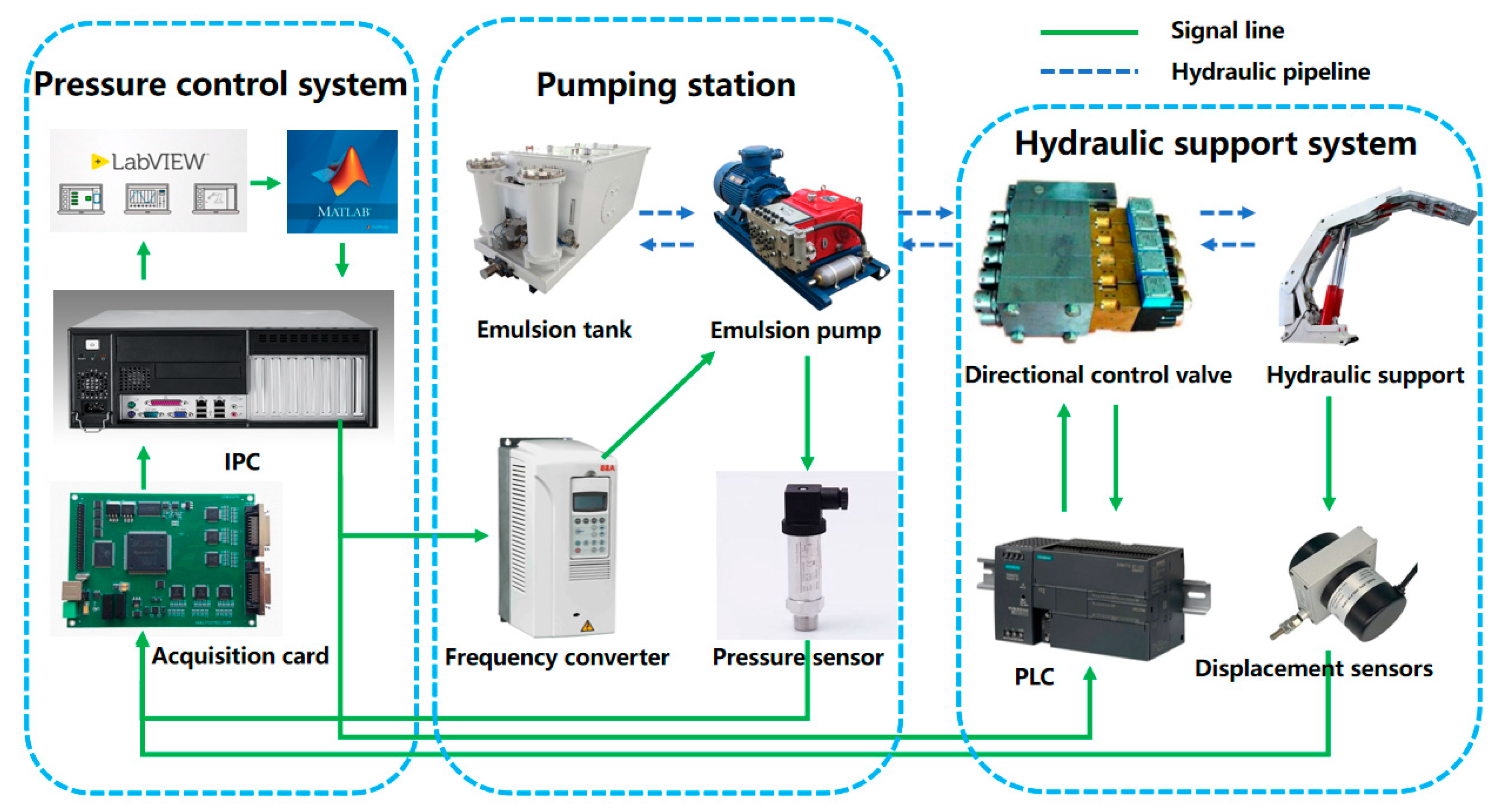
In order to obtain experimental data to validate the simulation model, a hydraulic support system experimental platform was built. The experimental platform included three parts: emulsion pump station system, hydraulic support system, and control system. The experimental equipment and principle are shown in Figure 1 and Figure 2, respectively. The emulsion pumping station consists of one emulsion tank and two emulsion pumps, each of which is driven by a frequency converter and equipped with unloading valves and accumulators. The hydraulic support system adopts three sets of cylinders to simulate the hydraulic support, the simulated support cylinder and the loading cylinder interact to realize the loading, of which two sets simulate the column cylinder and one group simulates the pushing cylinders. The pressure sensors and flow sensors were installed at the pump outlet, and displacement sensors and pressure sensors were installed in front of the cylinder for feedback. The hardware of the control system mainly consists of an industrial computer (ADVANTECH, Taiwan, China), PC (Lenovo, Shanghai, China), PCI data acquisition card (Art-Control, Beijing, China), and PLC controller (Siemens AG, Munich, Germany), and the software uses a Simulink/Real-time control system (MATLAB 2022b) and writes the control program of the voltage regulator fluid supply in Labview. In addition, a filter module is added to the control program to filter the signal collected by the sensor. The details of the experimental equipment are shown in Table 1.

2.2. Establishment and Verification of the Simulation Platform

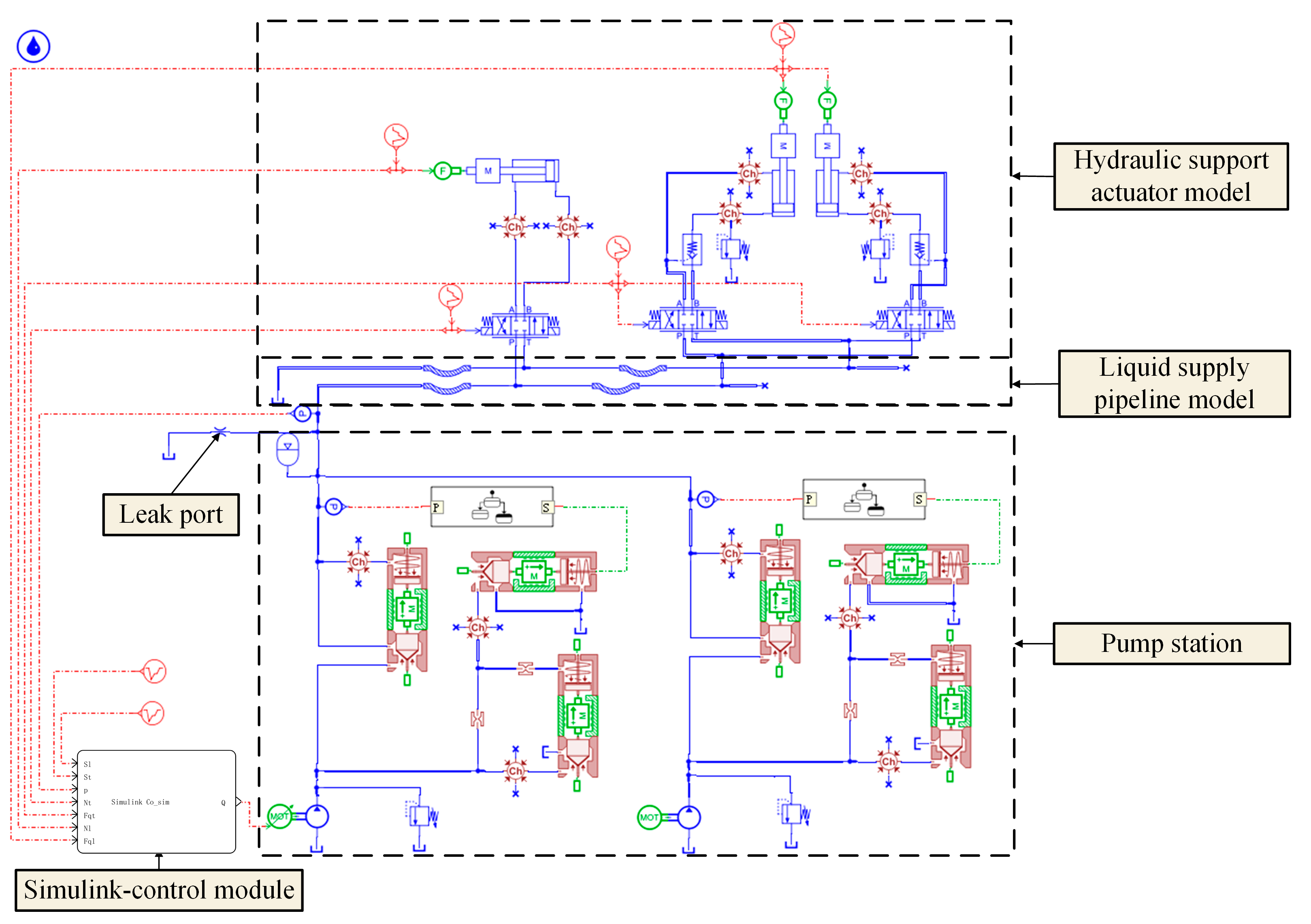
The AMESim-Simulink co-simulation model is established according to the built experimental platform, and the parameters of each device are set according to the actual experimental equipment parameters to ensure the authenticity and reliability of the calculation. The co-simulation model is shown in Figure 3.
In order to avoid the interference of redundant factors, the following simplification and assumptions are made in the establishment of the simulation model: (1) the bulk modulus and absolute viscosity of the emulsion are constant. (2) The emulsion is an incompressible fluid, and its density is independent of temperature. (3) Do not consider the leakage of each component in the system. (4) Ignore the influence of the electromechanical conversion device on system characteristics. (5) Cavitation is not considered.
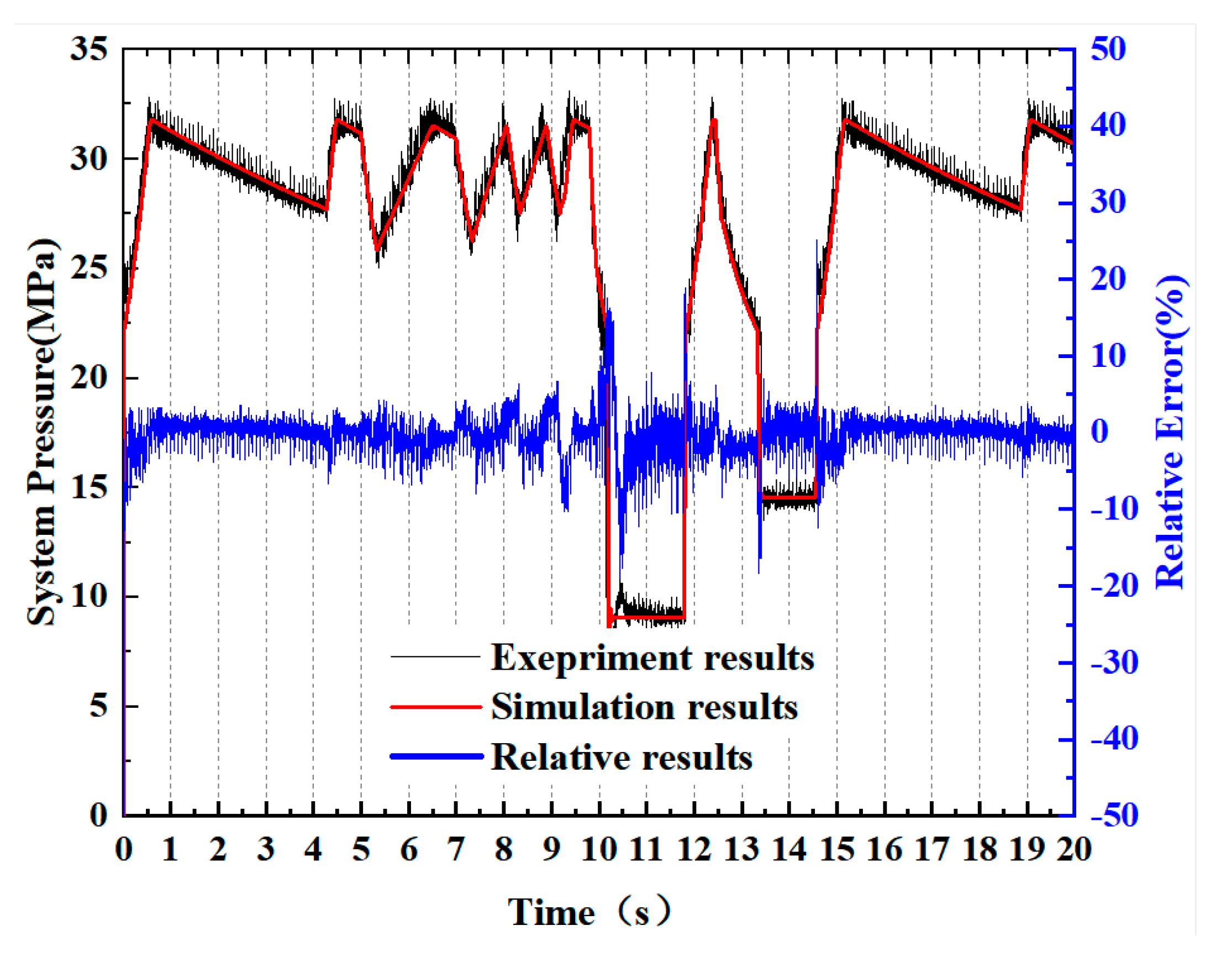
Based on the established hydraulic system simulation model, the accuracy of the simulation model is verified by comparing the simulation results with the test results under the rated fluid supply condition. Start emulsion pumps (3) and (4) before the operating test. The speed of the converter is adjusted, and the two emulsion pumps operate at the fluid supply flow of 200 L/min and 80 L/min, respectively. When the emulsion pump runs stably, the rated fluid supply flow of the pumping station is 280 L/min. The system pressure data of the simulated hydraulic support were collected when the hydraulic support performed no action with leakage, and the actions of descending, pulling, raising, and pushing were performed. The comparison of experiment and simulation results under rated fluid supply conditions is shown in Figure 4.
As shown in Figure 4, the overall change trend of system pressure measured by experiment is in good agreement with the simulation results under rated fluid supply conditions. It is divided into five stages, which are hydraulic support in no action leakage stage, descending, pulling, raising, and pushing actions. In the pulling stage, the system pressure fluctuates frequently in the operating pressure range of the unloading valve because the fluid supply flow is greater than the fluid demand of the system. On the contrary, due to the large demand for fluid in the system, the fluid supply is insufficient in the raising and pushing stage. The minimum system pressure drops to 8.9 MPa, and the maximum pressure fluctuation is 22.6 MPa. The maximum relative error and the average relative error between the simulation results and the experimental results are 16.70% and 3.73%, respectively, and the experimental results have good consistency with the simulation results, which verifies the validity of the simulation model of the hydraulic support system.

2.3. Establishment of Optimal Flow Datasets under Different Operating Conditions

2.3.1. Steady-Pressure Fluid Supply Process

Nowadays, many underground hydraulic support systems in coal mines are rated fluid supply, and the system pressure range is maintained through the unloading valve in the pump station. The stability of the system pressure is an important measure of the quality of fluid supply from the emulsion pumping station, while the fluid supply flow rate also determines the hydraulic support operating speed and the degree of system pressure stability. Figure 5 illustrates the measured data of hydraulic support system pressure in a mine, and the rated flow rate of the emulsion pump station is 400 L/min.
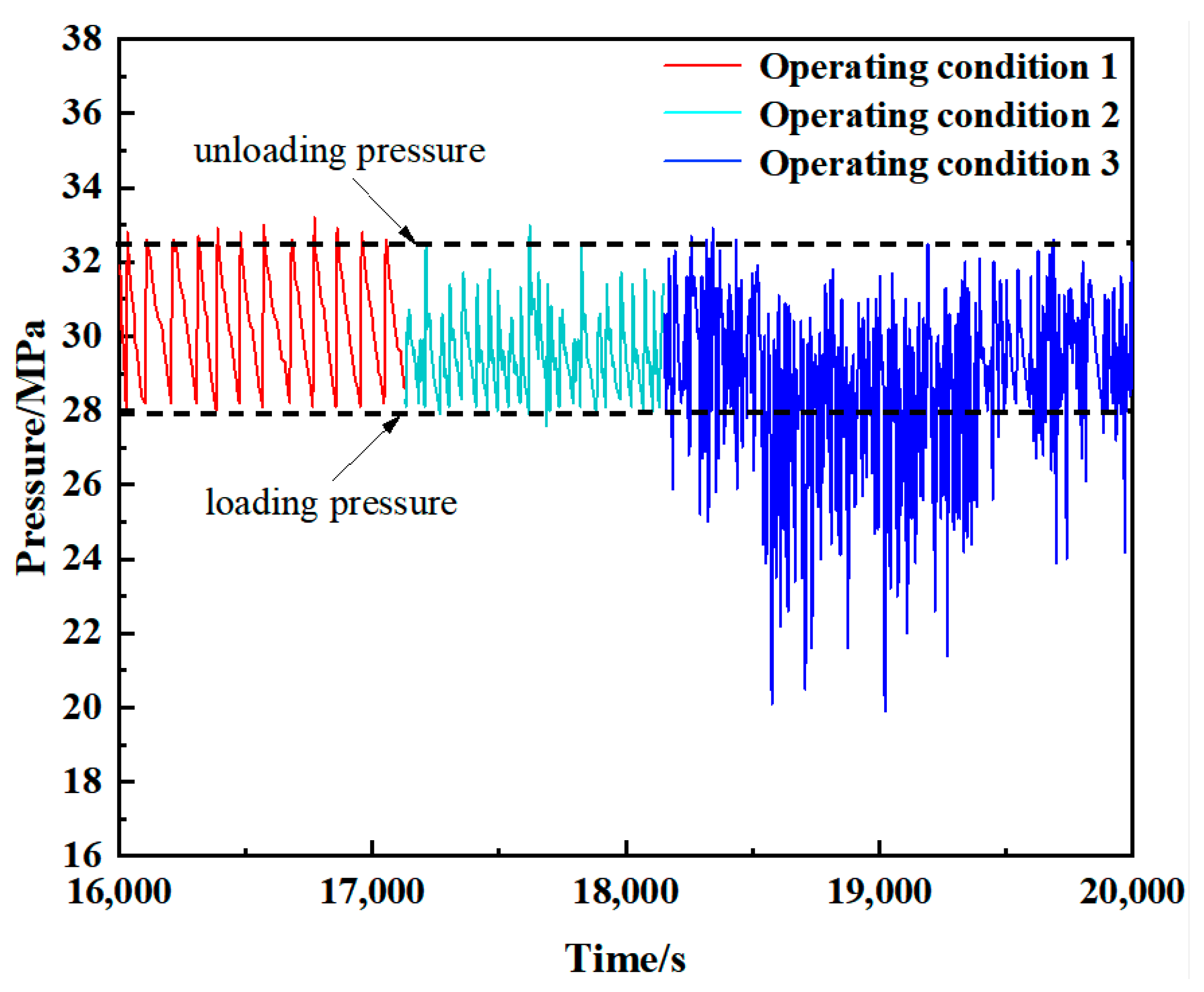
As can be seen from the system pressure data in Figure 5, because the different operating modes of the hydraulic support actuator (descending, pulling, raising, and pushing actions) have great differences in the demand for fluid supply flow, and the loads are strongly time-dependent, this results in corresponding sudden changes in system pressure. According to the classification of different amounts of fluid consumption of the hydraulic support in the working face, the operation of the working face hydraulic support is divided into three typical working conditions, and there are different degrees of pressure fluctuations in each working condition:
Operating Condition 1: When the hydraulic support is inoperative and there is only a small amount of system leakage, the leaking fluid is supplemented by the accumulator, and the pumping station does not supply fluid to the system. At this stage, the system pressure fluctuates regularly within the pressure limit of the unloading valve. Under this condition, the demand for system fluid is very small, and excessive output flow of the pumping station will lead to low system efficiency and increase the amount of system pressure fluctuation. Operating Condition 2: When the amount of fluid used by the hydraulic support to perform the action is less than the amount supplied by the pumping station, the system pressure continues to fluctuate frequently within the pressure limit of the unloading valve, resulting in system instability. At the same time, due to the frequent action of the unloading valve, the pump station output flow cannot fully enter the system and act on the actuator, but directly into the fuel tank through the unloading valve, which affects the movement speed of the support. Operating Condition 3: When the amount of fluid used by the hydraulic support to perform the action is greater than the amount of fluid supplied by the pump station, the system pressure is greatly reduced until it rises after the operation of the hydraulic support is completed, which may cause the cylinder pressure of the column to fail to reach the ideal initial support force, and the hydraulic support moves slowly due to the low system pressure in the whole process.
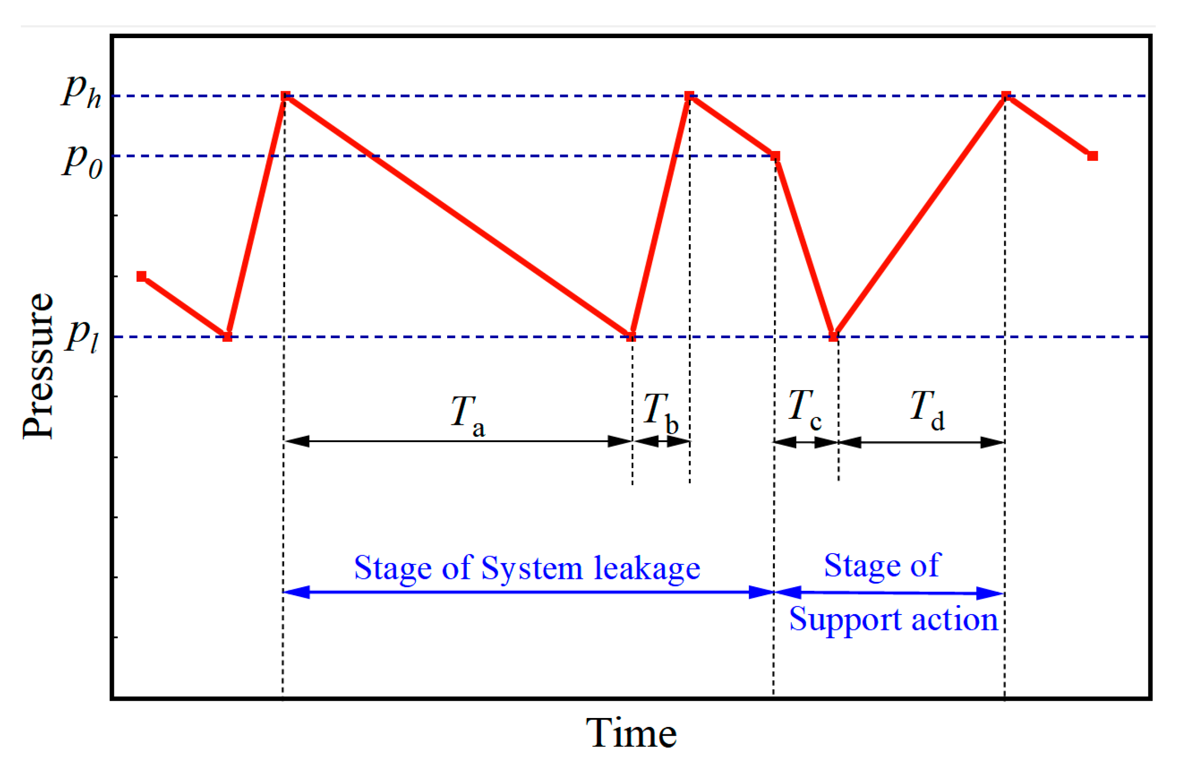
For this reason, a steady-pressure fluid supply method adapted to the flow requirements of different working conditions of the hydraulic support was proposed. Reasonable fluid supply flow was output through the emulsion pump station to ensure that the system pressure remained relatively stable within a high-level range. The ideal steady-pressure fluid supply process pressure curve is shown in Figure 6. The process is divided into four stages: the system slowly leaks when the pump station is not replenished (stage a), the system slowly leaks when the pump station is quickly replenished (stage b), the support action during the accumulator supply (stage c), the support action during the pump station supply (stage d). Through this pressure process curve, analyzing the support system of the ideal steady-pressure fluid supply of the four phases of the hydraulic characteristics of the theoretical analysis is specified as follows.
(a) Stage of pump station not replenishing when the system is leaking slowly
In this stage, the hydraulic support does not perform any action, and the system slowly leaks fluid, because the system pressure is higher than the unloading valve loading pressure pl, the pumping station is in the unloading state, the pumping station does not replenish the fluid to the system, and the leaking fluid is replenished by the accumulator, which leads to a slow reduction of the system pressure from the unloading valve unloading pressure ph to pl. The duration of this stage:
T a = V h V l Q o u t
where Ta is the duration of stage a; Vh is the volume of the accumulator when the system pressure is ph; Vl is the volume of the accumulator when the system pressure is pl. Qout is the leakage volume of the system.
The relationship of accumulator pressure and volume:
p x · V e V x = p e · V e
where pe is the rated pressure of the accumulator; Ve is the rated volume of the accumulator; px is the current pressure of the accumulator; and Vx is the current volume of the accumulator.
(b) Stage of pumping station rapid replenishment when the system is leaking slowly
In this stage, the hydraulic support does not perform any action, the system leaks slowly, because the system pressure is higher than pl, the pumping station is in the loading state, the pumping station replenishes the fluid to the system quickly. Due to the short duration of this stage, the leakage of the system can be ignored, the output flow of the pumping station is regarded as all the fluid charging to the accumulator, and the system pressure is rising rapidly from pl to ph. The duration of this stage is:
T b = V h V l Q p
where Qp is the flow rate of fluid supplied from the pumping station.
(c) Stage of accumulator fluid supply during the hydraulic support operation
In this stage, the hydraulic support began to act, due to the system pressure being higher than pl, the pumping station is in the unloading state, the pumping station did not supply fluid to the system, the hydraulic support action power source for the accumulator, the accumulator output pressure fluid to push the hydraulic support hydraulic cylinder, resulting in a rapid decline in system pressure to pl, at this time the hydraulic support hydraulic cylinder to the initial speed v1 into the pumping station supplying the fluid stage.
v l = Q e Q o u t A i n
where Qe is the flow rate of fluid supply to the accumulator, Qout is the fluid leakage of the system; Ain is the action area of the hydraulic support feeding cylinder.
(d) Stage of pumping station fluid supply during hydraulic support operation
At the beginning of this stage, the hydraulic cylinder of the hydraulic support moves at the initial speed vl, the system pressure is the loading pressure of the unloading valve pl, and the pump station enters the loading state to supply fluid to the system. Ideal steady-pressure fluid supply situation system pressure rises uniformly, when the hydraulic cylinder completes the current action at the same time, the system pressure rises to ph. Hydraulic cylinder force to meet the formula:
p A i n = F q + θ v A o u t + m a
where p is the real-time pressure, Ain and Aout are the area of the hydraulic cylinder inlet and outlet chambers, respectively, Fq is the load on the hydraulic cylinder, θ is the resistance coefficient of the hydraulic cylinder in relation to the speed of action, m is the mass of the hydraulic cylinder, and a is the acceleration of the hydraulic cylinder action. The hydraulic cylinder action stroke is:
S = v l T d + 1 2 a T 3 2
According to the principle of volume balance within the hydraulic system, the emulsion pumping station supply flow rate is the sum of the flow rate required for the action of the hydraulic cylinder of the hydraulic support, the flow rate required for the charging of the accumulator, and the leakage flow rate of the system, which satisfies the following formula:
Q p T d = L A i n + Q o u t T d + V h V l
According to Formulas (1)~(7), when the rated capacity of the accumulator and the amount of fluid leakage in the system are constant, the flow rate of the ideal steady-pressure fluid supply changes with the action area, action stroke, and load size of the hydraulic cylinder in the execution of the hydraulic support.

2.3.2. The Concept of Optimal Flow Rate

As mentioned before, in the existing research [23], the control strategy of the output flow rate of the pumping station is based on the optimal flow rate of the current actuator action, which is always a fixed and stable flow rate of the current actuator action, ignoring the influence of the actuator resistance and load. However, the downhole working conditions are complex and variable, the actuator resistance and load have strong time-varying characteristics, and the coupling of each factor with the fluid supply flow has a great influence on the system pressure. Therefore, under different working conditions, a fixed supply flow rate will limit the movement speed of the hydraulic cylinder and cause the system pressure to fluctuate.
In order to achieve the highest operating efficiency of the emulsion pump under partload conditions, the flow output control can be further relaxed so that a higher set of flow outputs can be used. In order to achieve the optimum flow output control of the emulsion pump, the objective function is defined as:
p s e t = M a x Q
The optimized constraint equation is expressed as Equation (9), which is used to maintain an acceptable system pressure.
P l p s e t P h
where Pl and Ph are the lower and upper limits of system pressure, which are 28 MPa and 31.5 MPa (unloading valve operating pressure), respectively.
Since the system pressure will be increased by increasing the emulsion pump flow output, the above optimization problem can be simplified to find the maximum flow output value Qset, at which the system pressure can be kept high to allow the actuator to achieve a faster speed of operation. Therefore, under different operating conditions, there will be a corresponding value of Qset.
On the other hand, higher flow output values also lead to higher system pressure. When the system pressure value reaches the regulated unloading pressure of the unloading valve, the unloading valve opens, leading to unloading of the pumping station, and ultimately there are fluctuations in the system pressure due to the oversupply of fluid, which reduces the quality of the fluid supply. Therefore, in order to maintain acceptable system pressures, the fluid supply flow should be limited to the range of the best control method to be developed. In the current development, the lower limit of the system pressure Pl is set to 28 MPa, which is the closing pressure setting value of the unloading valve. The upper limit of the system pressure, Ph, is set to 31.5 MPa, which is the opening pressure setting of the unloading valve.
Therefore, when the system pressure is higher than 28 MPa, the higher system pressure accelerates the actuator’s movement [24] and ensures a faster movement speed maintained by the actuator. In the process of determining the Qset value, when the matched pressure value p reaches 31.5 MPa, the control method adjusts Qset downwards to avoid unloading the unloading valve until p is in the range of 28–31.5 MPa.

2.3.3. Optimal Flow Dataset under Different Working Conditions

A simulation model is built to simulate a hydraulic support; the purpose is to establish an emulsion pump output flow dataset and set the Qset dataset under different working conditions by artificially controlling the flow rate of the fluid supply, so as to realize the effect of the steady-pressure fluid supply as described in Section 2.3.1. Under specific working conditions, the inlet and outlet areas of different hydraulic cylinders represent different types of hydraulic support movements, and the rest of the data are obtained through experimental records. The accuracy of the sensors and sampling intervals may cause some errors in some of the data, but these errors are acceptable for the accuracy requirements of the flow prediction of the steady-pressure fluid supply.
The actual value of the system pressure p is limited to between 28 MPa and 31.5 MPa. The required system pressure value is adjusted according to the difference between the actual system pressure value p and the set pset, thus adjusting the output flow rate of the emulsion pump to cope with the actual system pressure. The emulsion pump regulates the required system pressure with a fixed output flow rate and supplies fluid to the actuator at this system pressure. Thereafter, the output flow rate from the experiment can be used as the desired Qset, which can then be specified as the optimum output flow rate Qset of the emulsion pump for that particular operating condition, with the goal of maximizing system pressure and minimizing system pressure fluctuations.
Using the simulation model of the analogue hydraulic support, obtain the dataset of emulsion pump output flow rate for different working conditions set up as represented by the four actions of the hydraulic support including descending, pulling, raising, and pushing actions, which contains 300 sets of data on the hydraulic support action type, action stroke, hydraulic cylinder load, and pipeline length.

3. Establishment of a GRNN Model for Predicting the Optimal Dataset of Flow Rates

This section attempts to present a new approach aimed at providing stabilization of emulsion pressure. The GRNN artificial neural network modelling approach has the advantages of simple network architecture, fast convergence, and excellent prediction results when the sample data are small and unstable, and has been widely used in the fields of heat load prediction [25], hydraulic control [26], time series prediction [27], and trajectory tracking control [28]. Its specific modelling approach is extensively described in the open literature [29]. It is suitable for the problem of prediction of unstable data under such complex operating conditions as underground hydraulic support systems.
According to the optimal flow rate requirements introduced in the previous section, the optimal flow output dataset of the hydraulic support system under different working conditions was determined by simulation, and based on the relationship between the inputs of the obtained dataset and the corresponding outputs, a GRNN prediction model connecting the optimal flow output value with four environmental parameters, namely the type of action of the hydraulic support, the stroke of the action, the length of the pipeline, and the load of the actuator, was established.

3.1. Input and Output Parameters of the GRNN Model

Previous studies [15,22] have shown that when the actuator action resistance coefficient, system leakage, and unloading valve set pressure are certain, the type of actuator action and action stroke, the length of the pipeline, and the actuator load are the main factors influencing the flow rate of the fluid supply, so these four parameters are specified as inputs to the GRNN model. At the same time, the optimal emulsion pump flow rate is specified as the only output parameter of the GRNN model. The flow rate when the system pressure profile is the steady-pressure fluid supply profile shown in Figure 6 is collected as the optimal steady-pressure fluid supply flow rate output.
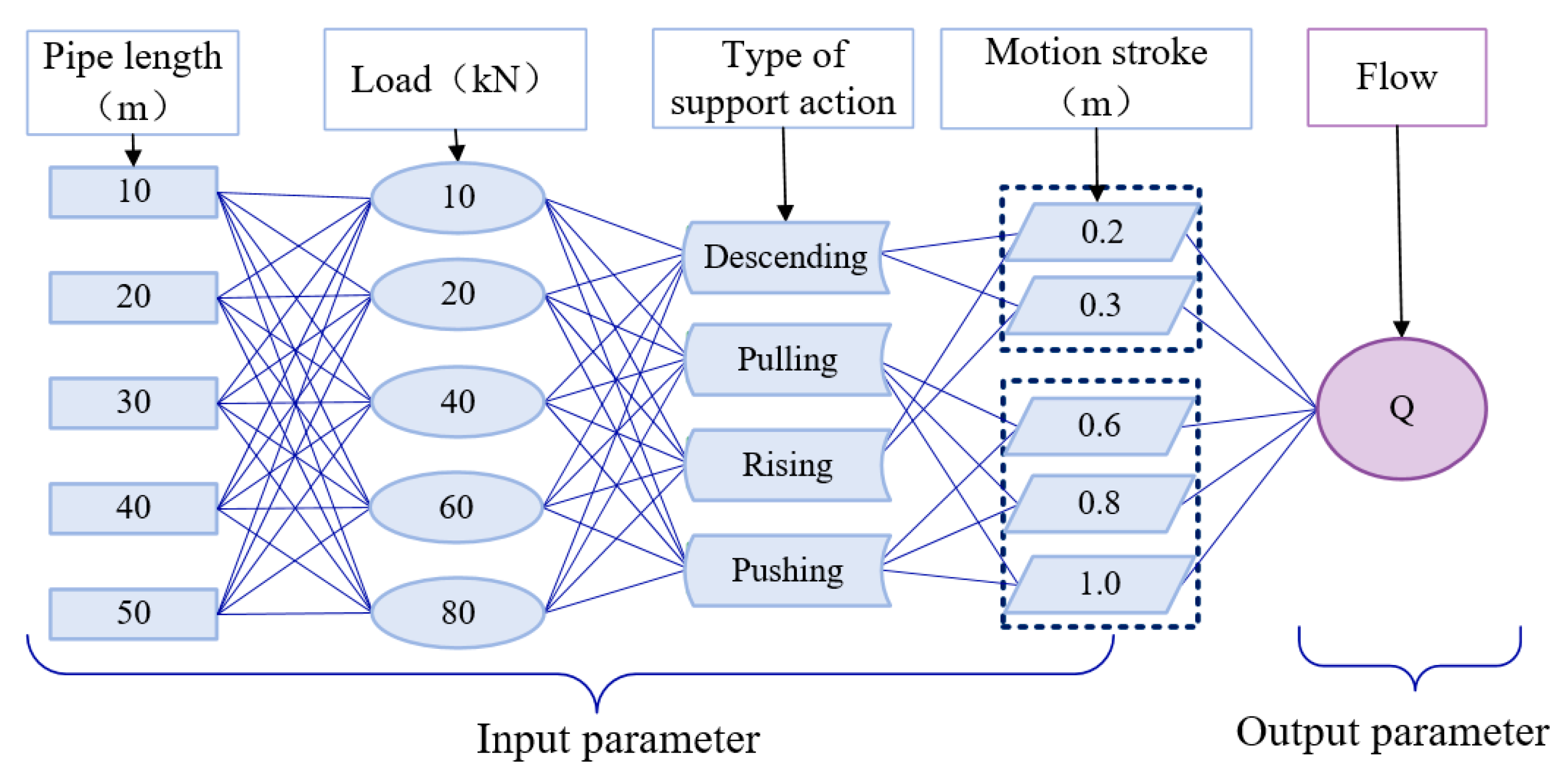
In order to be closer to the actual working conditions in the borehole, the size of the pushing cylinder is selected according to the ZY9200/25/50D shielded hydraulic support configuration cylinder. The action stroke range of descending, pulling, raising, and pushing actions is determined according to the actual working conditions of top removal, and the load range of the actuator is calculated by the size of the pushing cylinder and the allowable range of system pressure. The optimal flow combination design scheme is shown in Figure 7.

3.2. Training and Testing of GRNN Models

The total number of available data is 300 groups, and the random division method is adopted. Considering the working characteristics of the hydraulic support, the main action is divided into four actions: descending, pulling, raising, and pushing, and the four actions have a large difference in the amount of fluid, so the experiments in this section randomly adopt 70% of the data in each action data as the training data, and the remaining 30% of the data as the test data, respectively. At the same time, the data underwent normalization processing before modelling to eliminate the effect of different magnitudes of data on the model error. The Min–Max normalization processing was used with a mapping range of [0, 1], and the transformation function is as follows:
x * = x x m i n x m a x x m i n
where x* represents the normalized data, xmax is the maximum value of the sample data, and xmin is the minimum value of the sample data.

3.2.1. Training of the GRNN Model

A GRNN neural network for predicting the optimal flow output was constructed. There are four layers in the GRNN model, an input layer, a pattern layer, a summation layer, and an output layer [30,31]. The model structure is shown in Figure 8. The input layer consists of four simple neurons, which pass the four input parameters of hydraulic bracket action type N, hydraulic cylinder action stroke S , pipe length L, and actuator load Fq directly to the pattern layer, which contains 210 neurons, where each neuron corresponds to a different training sample, and the transfer function of the neurons in this layer is a Gaussian function [32,33]:
φ i = e x p D i 2 2 σ 2 i = 1,2 , , n
where φ i is the network output of each neuron in the pattern layer, the weight function of the layer is D i 2 = x x i T x x i , x is the input vector, xi is the ith training sample corresponding to the ith neuron, σ is the smoothing factor. When σ is too large, the model will be insensitive to the changes in the details of the input data and will not learn enough, which may reduce its adaptability to new data. When σ is too small, the model will be too sensitive to the changes in the input data, resulting in overfitting, which may reduce the stability of the network.
In the summation layer, two neurons are used to perform the summation operation, a simple arithmetic summation neuron and a weighted summation neuron. Finally, the output layer outputs the predicted value, consisting of one neuron representing the optimal emulsion pump flow output:
y = i = 1 n y i e x p D i 2 / 2 σ 2 i = 1 n e x p D i 2 / 2 σ 2
From Equation (12), when the GRNN model is developed using the training dataset and its structure and weights are determined, the smoothing factor σ has an important impact on the performance of the GRNN model, so in order to obtain the optimal prediction results and to avoid over-smoothing of the data due to too large a value of σ or over-fitting of the data due to too small a value of σ, the parameter smoothing factor obtained by the cross-validation method [23] is used as parameter values, the optimal value of σ was determined based on the expected error percentage EEP [25], the optimal σ value was determined to be 0.06 according to Equation (13), and the minimum EEP value was 1.82%.
E E P = i = 1 210 y ^ i y i 2 / 210 y m a x × 100 %
where y ^ i is the ith predicted flow output value, yi is the flow output value in the ith dataset, and ymax is the maximum flow output value in the 210 sets of training data.
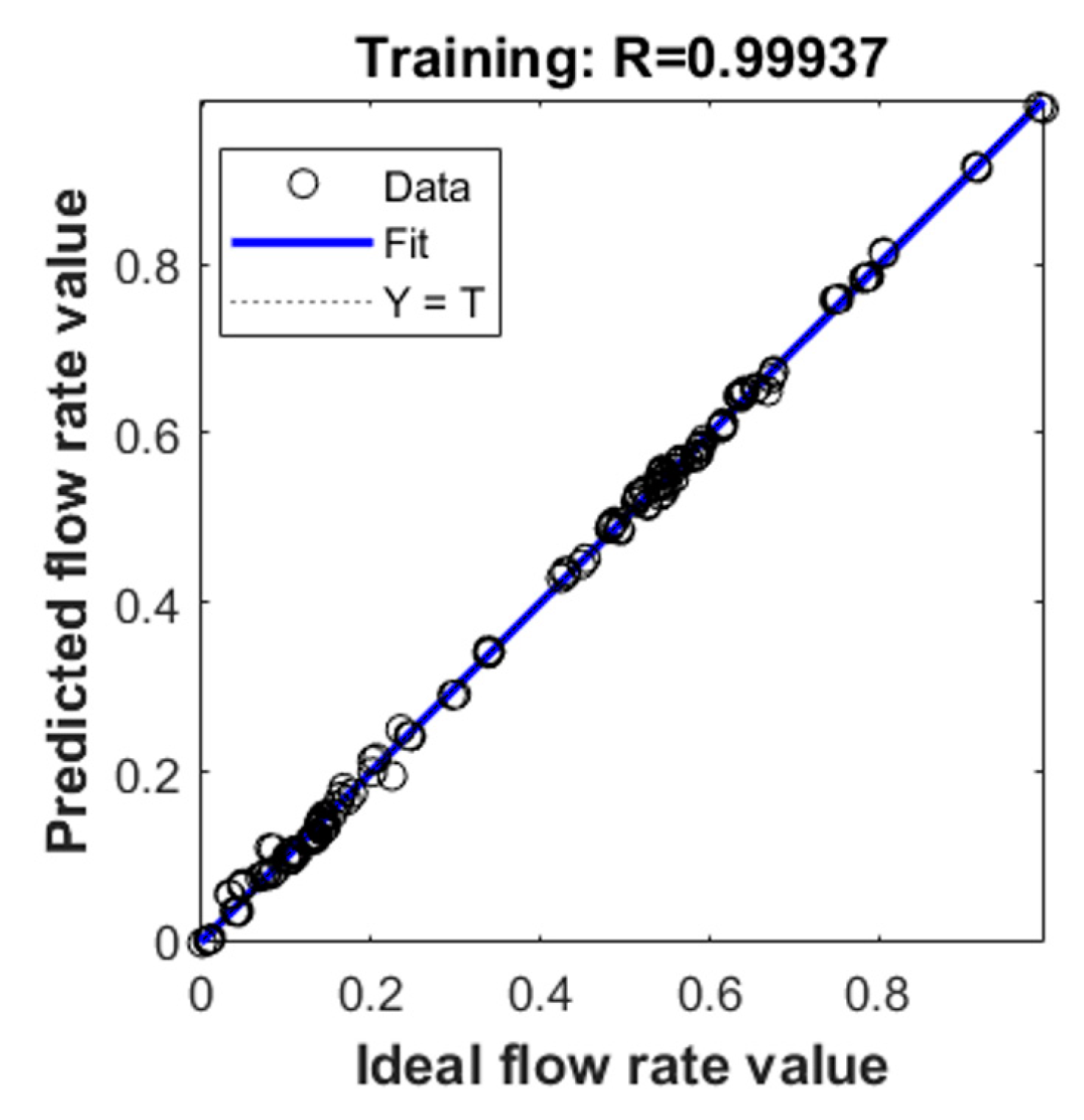
A GRNN model has been developed which can be used to predict the optimum regulated supply flow rate to be set for the emulsion pump under different operating conditions. In Figure 9, the predicted data using the GRNN model are compared with the training data. It can be seen that after training and fitting, the final average relative error of the training set flow rate values was obtained to be 0.94%, and the R2 value reached 0.9989 when training the GRNN model.

3.2.2. Testing of GRNN Model

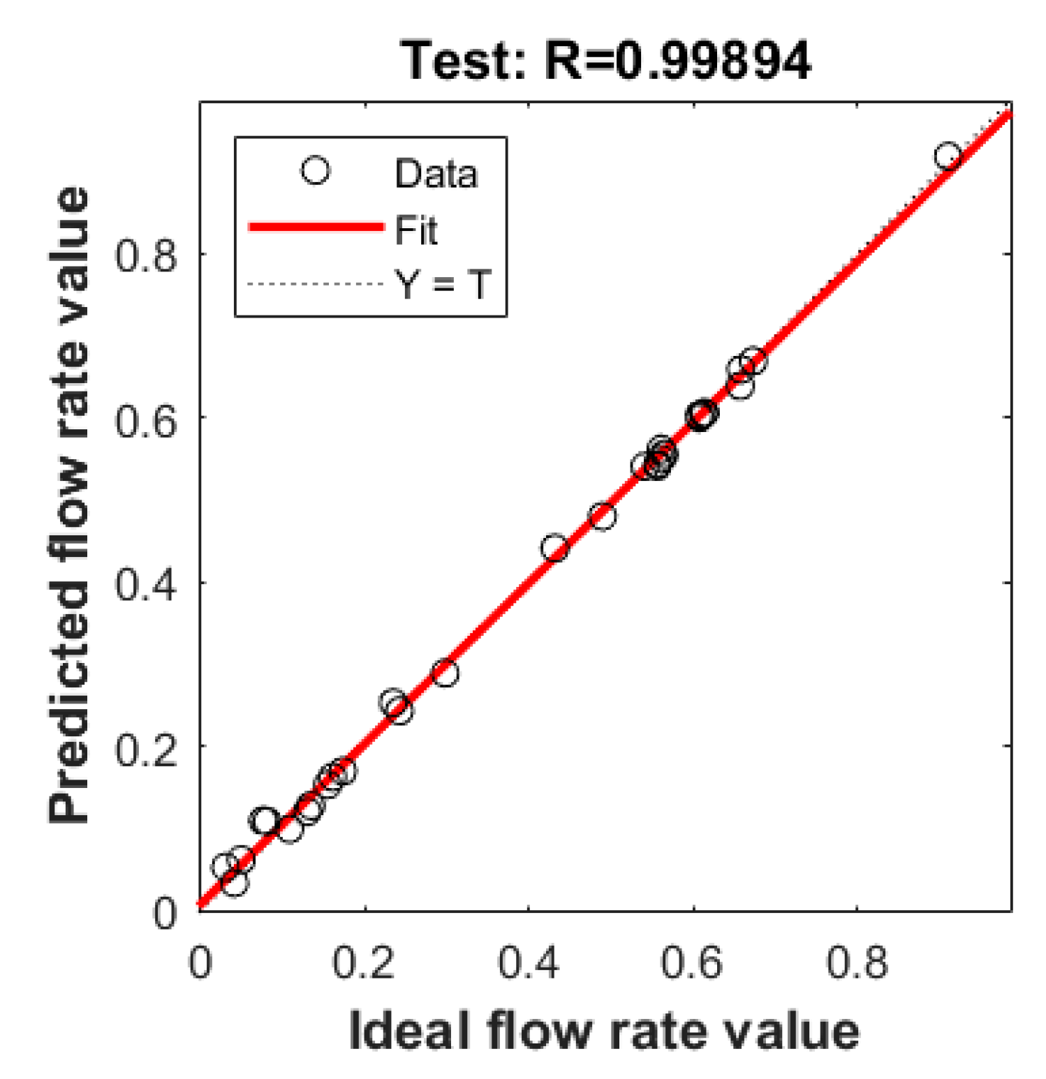
To test the learning ability of the model, the trained GRNN model was tested using the test set. Figure 10 compares the predicted supply flow values with the test supply flow values. The results show that after training and fitting, the average relative error of the final test set flow values is 1.02%, the R2 value during the model testing reaches 0.9985, and the correlation coefficient R reaches 0.99894. Therefore, the established GRNN model can be used to predict the optimal set of fluid supply flow of the hydraulic bracket system, which can satisfy the demand of steady-pressure fluid supply with high accuracy.

3.3. Online Updating of GRNN Model

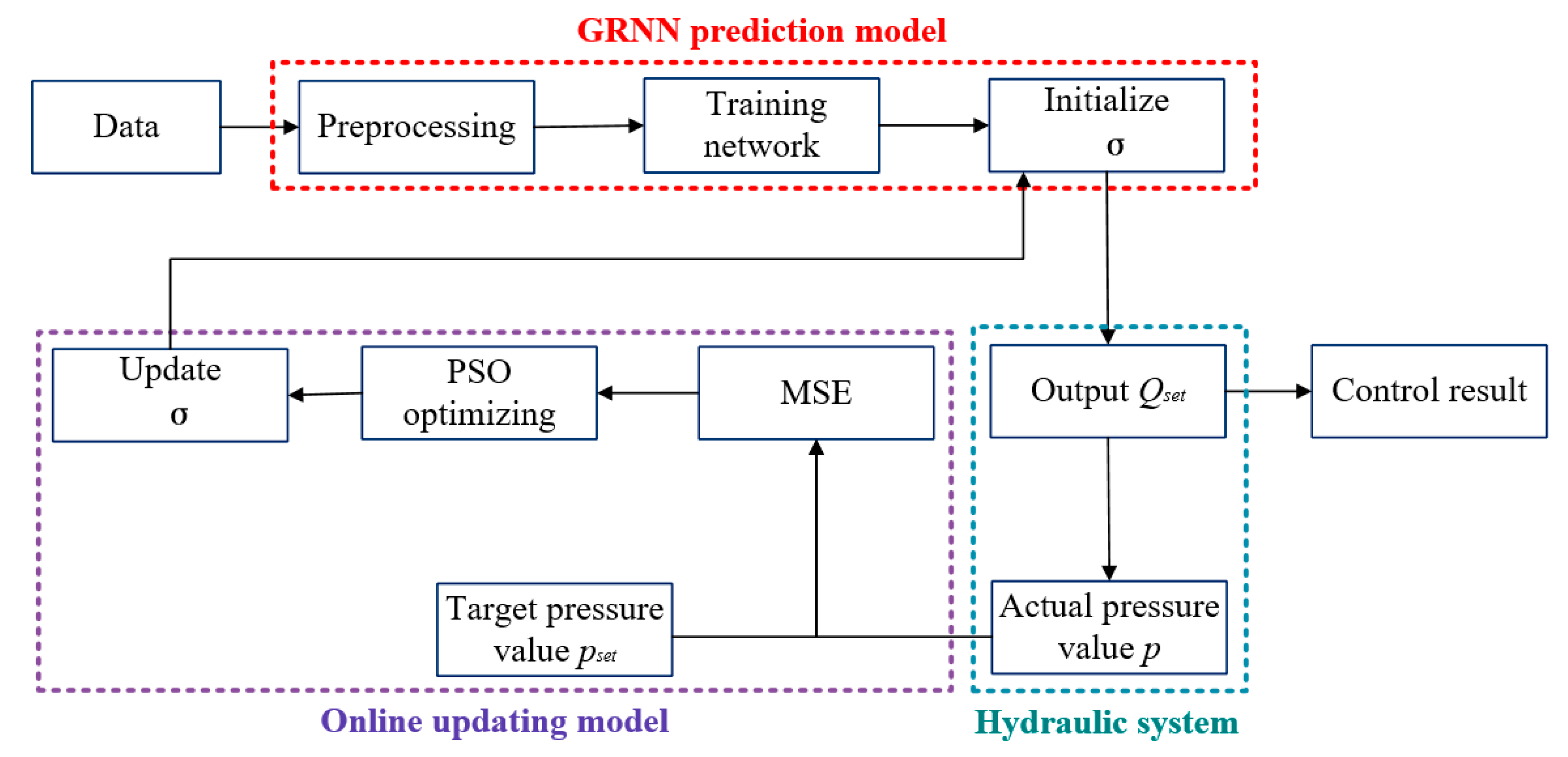
Because of the complex and changeable working conditions of hydraulic support, it is difficult for an offline algorithm to predict new working conditions, so an online updating prediction algorithm is needed to identify the model fitting in real time to ensure continuous learning to adapt to the new working conditions. The flowchart of the online updating control approach can be summarized as shown in Figure 11.
The smoothing parameter σ of the GRNN model is updated based on the PSO optimization algorithm, and the prediction accuracy of the GRNN model is improved by adjusting σ reasonably. The MSE of the collected mean square error between the system pressure and the ideal pressure for steady-pressure fluid supply within 0.5 s before and after the end of the hydraulic support action is selected to comprehensively evaluate the performance of the current GRNN, and the training dataset is constantly updated. The MSE calculation formula is as follows:
M S E = 1 N i = 1 N p ( t ) p s e t ( t ) 2
where N is the data length, p is the current pressure value, and pset is the target pressure value of steady-pressure fluid supply.
Taking MSE as the input of the PSO optimization problem, the fitness function of PSO is calculated, and the smoothing parameters in each time step are continuously calculated by PSO. Find the individual extreme value σbi = (σbi1,σbi2,...,σbim,) and the optimal position of population history σpb = (σpb1,σpb2,...,σpbm,), and the optimal smoothing parameter is obtained. Wherein, the speed and position updating formulas are, respectively:
V i m ( k + 1 ) = u V i m ( k ) + c 1 r 1 ( σ b i m ( k ) σ i m ( k ) ) + c 2 r 2 ( σ p b m ( k ) σ i m ( k ) )
σ i m ( k + 1 ) = σ i m ( k ) + V i m ( k + 1 )
where k is the number of iterations, Vim(k) is the mth dimension component of the velocity vector of the ith particle in the kth iteration, m = 1,2, …, M, u are inertia weights, c1 and c2 are acceleration weights, and r1 and r2 are random numbers in the interval (0,1).
u ( k ) = u m a x k ( u m a x u m i n i t e r m a x )
where: intermax is the maximum number of iterations.

4. A Numerical Study on the Development of Steady-Pressure Fluid Supply Method and Its Numerical Implementation

In the numerical research introduced in this section, the GRNN model is used to predict the optimal steady-pressure fluid supply flow rate, the GRNN model and AMESim/Simulink co-simulation model of the hydraulic support system are established, and the optimal control method of steady-pressure fluid supply is realized numerically. The self-adaptive steady-pressure fluid supply control simulation is carried out for single-cycle constant load and variable load conditions, respectively. In addition, the online updating of steady-pressure fluid supply control simulation of the unexpected working condition of system leakage, and the pressure fluctuation of the system, is obtained.

4.1. Single-Cycle Constant Load Steady-Pressure Fluid Supply Control

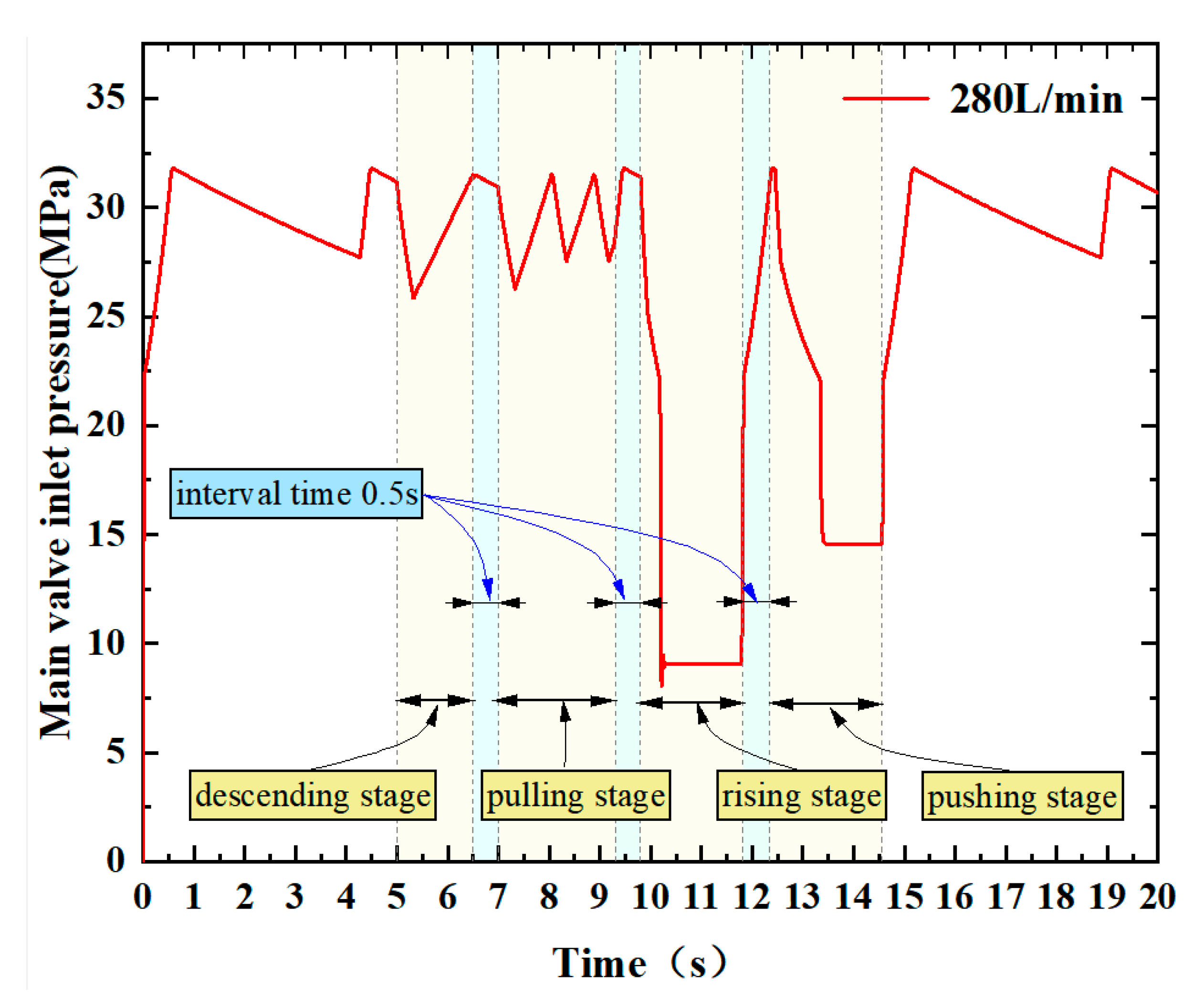
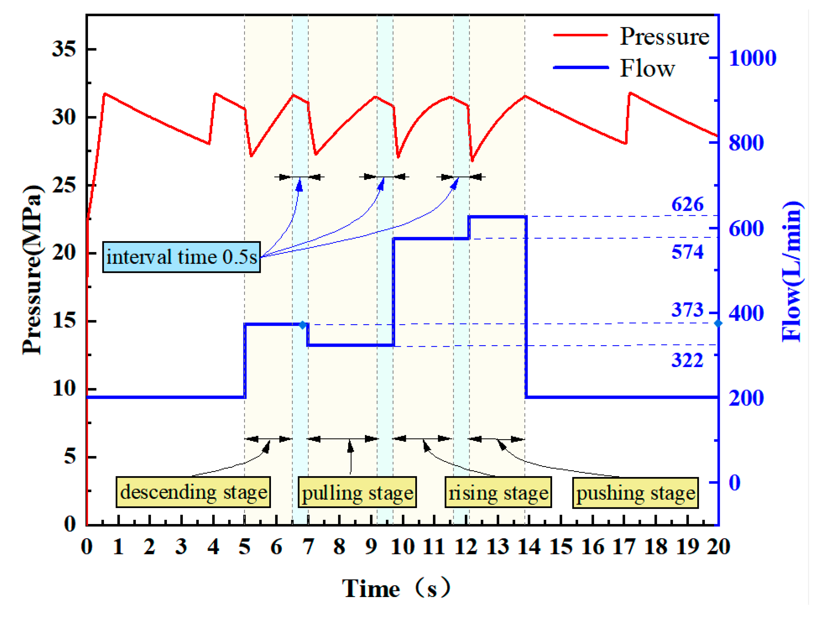
The action process of single-cycle hydraulic support with constant load is as follows: after the system is stabilized for 5 s, four actions of descending, pulling, raising, and pushing are executed in sequence, with a waiting time of 0.5 s before each action, and the load is constant. Under different working conditions of hydraulic support, the constant fluid supply flow will cause the system pressure to decrease in a large range or fluctuate frequently due to the imbalance between supply and demand of flow. As a contrast, the rated fluid supply mode and the steady-pressure fluid supply mode are taken as the research objects. In the simulation model, the rated fluid supply flow rate of 280 L/min and the optimal steady-pressure fluid supply flow rate mentioned above are used to supply fluid to the system, respectively. The pressure curves of the system are shown in Figure 12 and Figure 13.
As can be seen from Figure 12, in the traditional rated fluid supply scheme, when the hydraulic support carries out the action of descending and pulling, the system pressure continues to fluctuate frequently within the pressure limit of the unloading valve due to the amount of fluid supplied by the pumping station being larger than that required by the actuator; when the hydraulic support carries out the action of raising and pushing, the system pressure decreases greatly due to the fluid supplied by the pumping station being smaller than that required by the actuator until it rises after the completion of the action.
As can be seen from Figure 13, the established method of steady-pressure fluid supply can significantly improve the hydraulic system pressure condition, effectively reduce the number of pressure fluctuations during the action of descending and pulling action as well as the amplitude of pressure fluctuations during the action of raising and pushing, and slow down the loss of hydraulic components caused by pressure fluctuations. At the same time, the system pressure is maintained at a higher level, which improves the movement speed of hydraulic support and reduces the cycle time of overall action from 9.61 s to 8.86 s, saving 7.8% of time.

4.2. Online Updating of Steady-Pressure Fluid Supply Control for Variable Load Conditions

The actual working condition of underground working face is very complicated, the load force on the actuator cannot be constant, the operation process of the hydraulic support follower will be affected by the load characteristics, and different loads have a large impact on the system pressure and fluid supply efficiency. It is difficult to adapt to the real-time demand of the working surface by only considering the constant load condition for fluid supply; therefore, for the variable load condition, the online update of the steady-pressure fluid supply control is proposed. When the load force on the actuator changes, the emulsion pump output flow dataset is adjusted online, so that the next moment of the fluid supply flow more closely matches the working conditions.
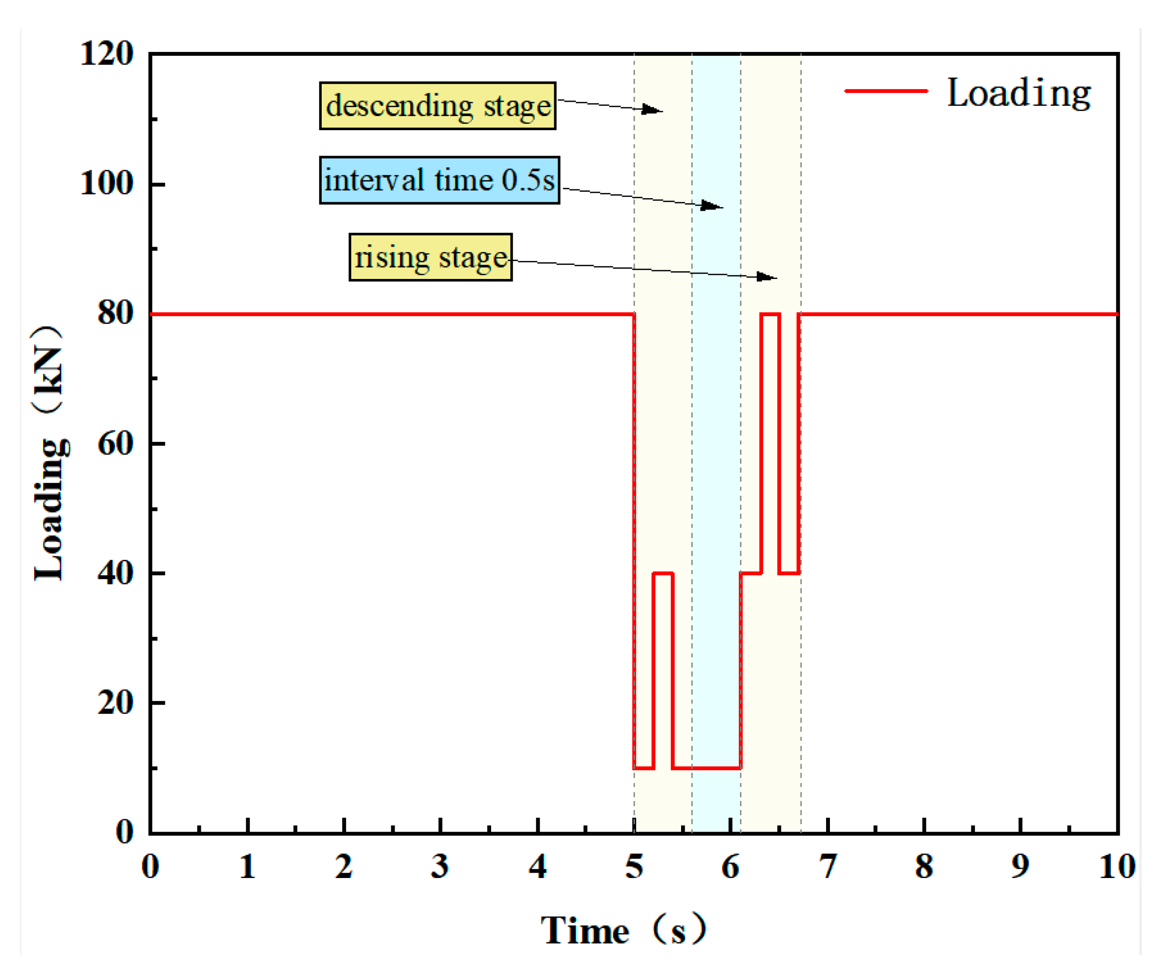
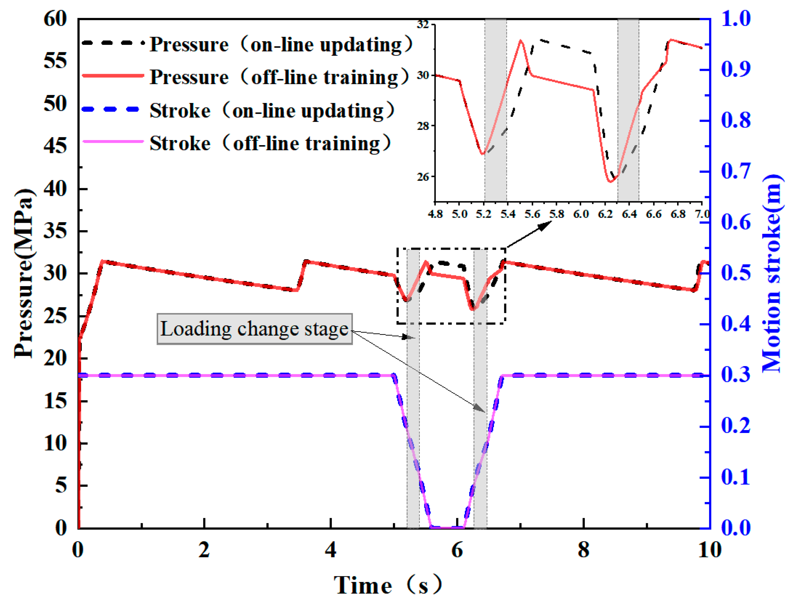
In the simulation, varying loads are applied in the operation stages of the simulated column raising and descending action stages, and the load signals are shown in Figure 14. Under the variable load conditions as shown in Figure 14, GRNN neural network trained offline and GRNN neural network updated σ online were used to control the steady-pressure fluid supply, and the pressure curves of the simulated column raising and descending action were collected, as shown in Figure 15. As can be seen from Figure 15: When the offline trained GRNN neural network is used for the steady-pressure fluid supply control, due to the sudden increase in load at 5.2 s and 6.3 s, the output flow of the emulsion pump station cannot adapt to the changing working conditions in time. As a result, the system pressure reaches the unloading pressure before the cylinder reaches the target stroke at 5.5 s and 6.7 s. At this time, the unloading valve is in the unloading state, and the output flow of the emulsion pump station cannot enter the system, so the flow control of the pump station is invalid. In contrast, when using the GRNN neural network of online updating σ for steady-pressure fluid supply control, in the stage of a sudden increase in load, due to excessive fluid supply flow, the system pressure change rate suddenly changes, and the cylinder moving speed changes, especially in the process of raising and descending action, but because the output flow is constantly updated to adapt to the load force, the system pressure does not fluctuate greatly. And the actuator completes the raising and descending action smoothly. The results show that the pressure change of the system is more stable when the GRNN neural network is updated and trained online, and it has good adaptability.

4.3. Online Updating of Steady-Pressure Fluid Supply Control

Because the downhole hydraulic support system is a high-pressure, large-flow, and long-distance fluid supply system, system leakage is often encountered in practical engineering. Under this working condition, due to system leakage, the output flow calculated by GRNN neural network trained offline in advance will be less than the steady-pressure fluid supply flow, which cannot meet the fluid demand of the actuator. Therefore, by online updating steady-pressure fluid supply flow control, the system pressure of the hydraulic support during each movement (descending, pulling, raising, and pushing) will be different from the target pressure of the steady-pressure fluid supply, and the dataset of fluid supply flow will be continuously adjusted to update the steady-pressure fluid supply flow trained under this working condition until the difference between the system pressure and the target pressure is controlled within the allowable range.
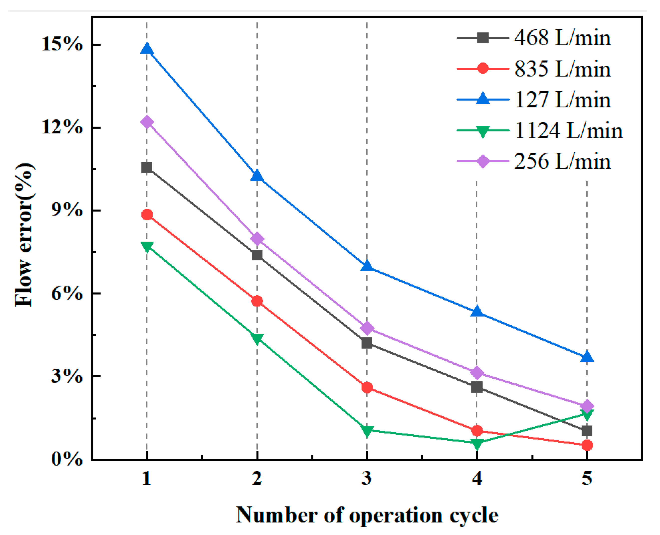
In order to simulate the system leakage condition above, a throttle port with an opening diameter of 3 mm is designed in the pipeline in the simulation model, the steady-pressure fluid supply control is carried out by online updating training, the system pressure is compared with the ideal target pressure of steady-pressure fluid supply at the end of each hydraulic support action, and the training dataset and the smoothing parameter σ are updated. The fluid supply flow during each operation cycle under five different working conditions was randomly recorded and compared with the optimal steady-pressure fluid supply flow under corresponding working conditions. The error is shown in Figure 16. It can be seen that when the system leaks, the error between the output flow calculated by the GRNN neural network trained offline in advance and the optimal steady-pressure fluid supply flow reaches a maximum of 14.8%. However, due to the online updating of σ, the error between the output flow and the optimal steady-pressure fluid supply flow decreases continuously with the adjustment of the fluid supply flow during each operation cycle until the fifth online updating control. The error is all controlled below 3.7%, which meets the requirements of pressure control of hydraulic support.
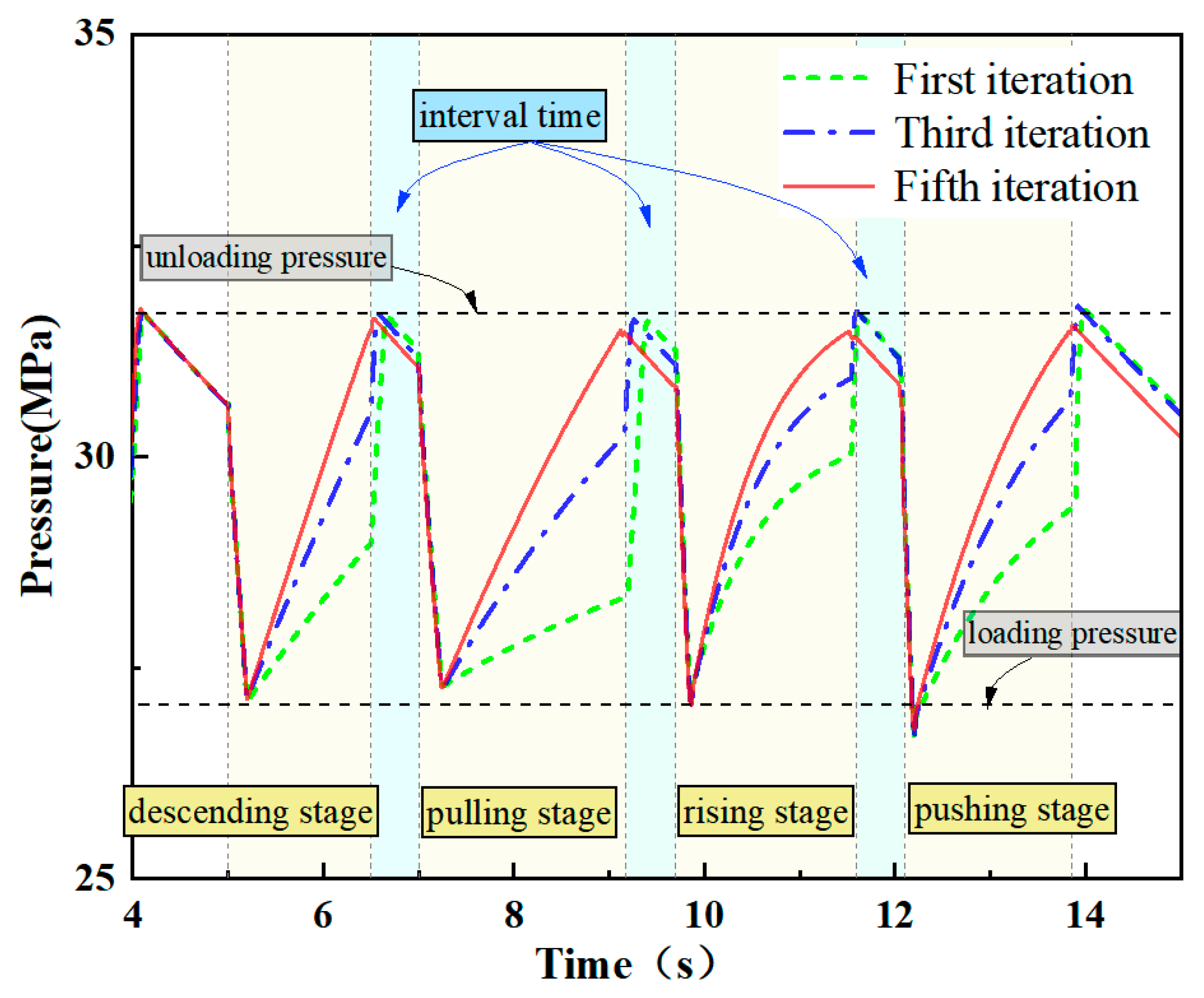
The changes in the system pressure curves under the online updating control for several times are shown in Figure 17. From the figure, it can be seen that during the first hydraulic support cycle action, the system pressure cannot rise stably due to the system leakage. At the moment of the end of the action, the difference between the system pressure and the unloading pressure is large, resulting in a sudden increase in the system pressure after the reversing valve action, causing a system pressure shock. With each online update control to adjust the amount of fluid supply, during each hydraulic support action, the system pressure rise tends to stabilize until the fifth online updating control; at the end of the hydraulic support action, the system pressure shock basically disappeared. This shows that the online updating GRNN neural network has good adaptability under sudden changes in working conditions.

5. Experiment

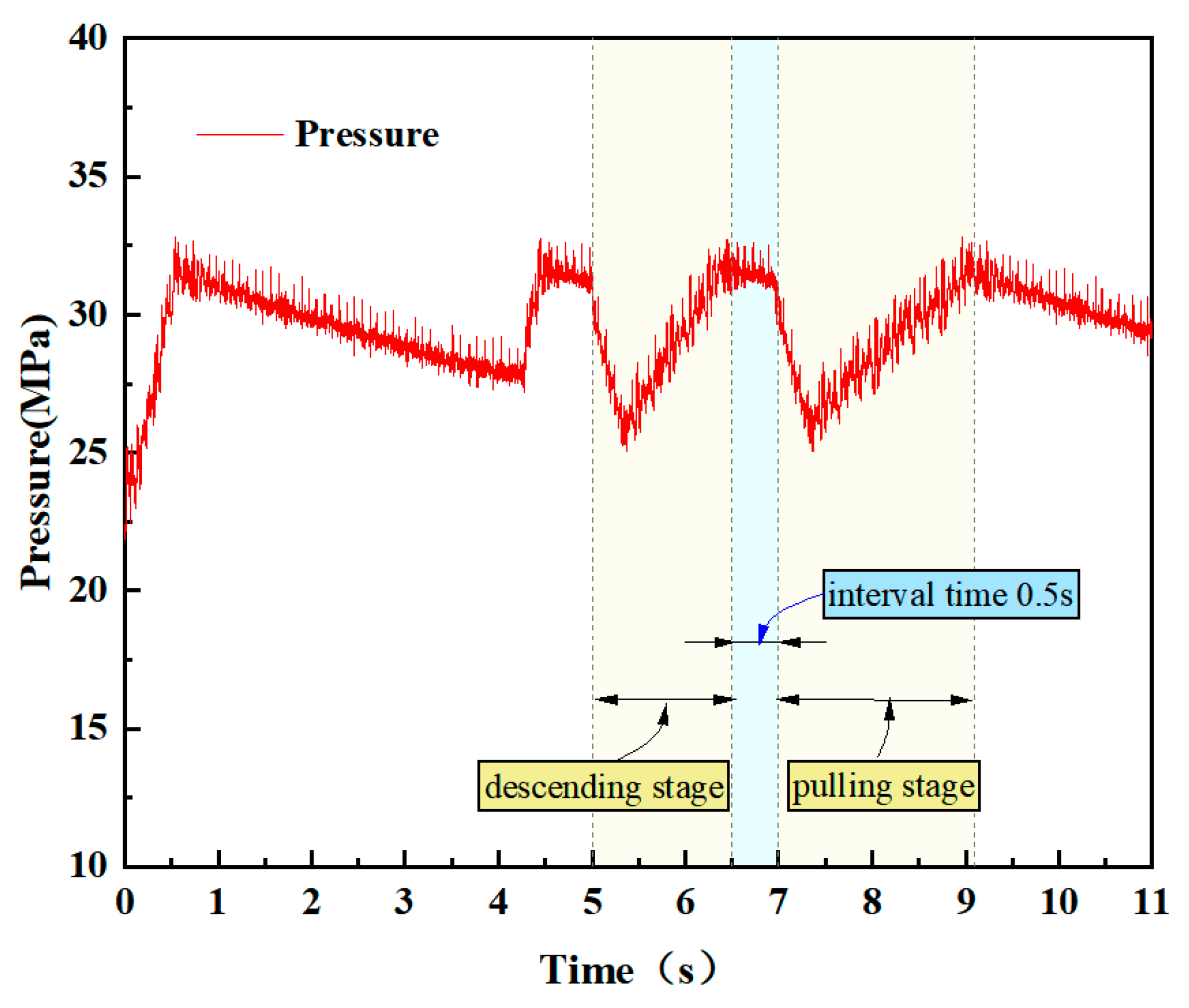
In order to further verify the executability of the control method, an experimental study was carried out through the constructed experimental platform. Since the total flow rate of the two emulsion pumps in the experimental platform is up to 280 L/min, this paper only studies the two action processes of descending and pulling, which use less fluid. The adjusting pressure of the proportional relief valve at the outlet of the loading pump is set to 20 MPa, which can achieve the loading force loading of the actuator. The flow output of the emulsion pumping station is controlled by the online updating steady-pressure fluid supply flow of the GRNN neural network, and after several online updates, the system pressure curve during the hydraulic support action is measured by the pressure sensor, as shown in Figure 18.
It can be seen from the pressure curve that the trend of the system pressure curve and the ideal steady-pressure control curve is the same during the operation of the hydraulic support, which verifies the consistency of the simulation and experiment results. There is no obvious pressure shock in the whole process, and there is only a small range of pressure fluctuation during each action, so the pressure stability of the system is good, which is beneficial to improve the smooth operation of the hydraulic support system.

6. Conclusions

In this paper, on the basis of analyzing the process of steady-pressure fluid supply in the hydraulic support system of the comprehensive mining face, the optimal steady-pressure fluid supply flow prediction model based on the online updating GRNN neural network is proposed for the optimal tracking control of the fluid supply flow output of the emulsion pumping station, and simulation and experimental validation are carried out. The following conclusions can be drawn:
(1) The GRNN model established based on the theory of optimal flow rate for steady-pressure fluid supply and the dataset evaluated by the simulation platform for simulating hydraulic support system has good prediction accuracy, and different operating parameters can be set according to different working conditions.
(2) The optimal control method of steady-pressure fluid supply flow developed based on online updating of the GRNN model can realize good control of hydraulic support system pressure. Under regular actuator load change conditions and special conditions such as system leakage, the PSO optimization algorithm can be updated online in real time to identify the model fitting in real time, ensuring continuous learning to adapt to new working condition characteristics, so as to maintain stable system pressure and improve the efficiency of following the machine to move the frame, which is of good practical performance.

Author Contributions

Conceptualization, P.X. and Z.K.; methodology, J.W.; software, P.X. and Y.P.; validation, P.X., Y.P. and B.Z.; formal analysis, Y.P. and T.H.; investigation, P.X.; resources, Z.K.; data curation, T.H., Y.P. and B.Z.; writing—original draft preparation, P.X.; writing—review and editing, P.X., Z.K. and J.W.; visualization, Z.K.; supervision, Z.K.; project administration, Z.K. and J.W.; funding acquisition, Z.K. All authors have read and agreed to the published version of the manuscript.

Funding

This work was supported by the National Natural Science Foundation of China (U1910212).

Data Availability Statement

This data is provided upon request due to privacy or ethical restrictions.

Conflicts of Interest

The authors declare no conflicts of interest.

References

  1. Li, R.; Liu, B.; Wang, D.; Chen, J.; Wang, T.; Zhou, R.; Wang, J.; Zhao, K.; Yu, Y.; Qin, H.; et al. Progress and application of intelligent fluid supply technology in working face. Coal Sci. Technol. 2022, 50, 247–253. [Google Scholar]
  2. Ran, L. Intelligent fluid supply technology in fully-mechanized coal mining face and its development trend. Coal. Sci. Technol. 2019, 47, 203–207. [Google Scholar]
  3. Su, J. Research on Constant Pressure Controlsystem in the Emulsion Pump Station; Taiyuan University of Technology: Taiyuan, China, 2012. [Google Scholar]
  4. Wang, G.; Xu, Y.; Ren, H. Intelligent and ecological coal mining as well as clean utilization technology in China: Review and prospects. Int. J. Min. Sci. Technol. 2019, 29, 161–169. [Google Scholar] [CrossRef]
  5. Zhou, R.; Li, S.; Wei, W.; Zhang, L.; Wang, W. Study on coupling mechanism of pressure and flow in following hydraulic system of mining face. Coal. Sci. Technol. 2020, 48, 129–136. [Google Scholar]
  6. Mamcic, S.; Bogdevicius, M. Simulation of dynamic processes in hydraulic accumulators. Transport 2010, 25, 215–221. [Google Scholar] [CrossRef]
  7. Van de Ven, J.D. Constant pressure hydraulic energy storage through a variable area piston hydraulic accumulator. Appl. Energy 2013, 105, 262–270. [Google Scholar] [CrossRef]
  8. Li, Z.; Guo, Y.; Lian, Z. Analysis of frequency characteristics of hydraulic support’s liquid pipeline. J. Taiyuan Univ. Technol. 2012, 43, 203–206. [Google Scholar]
  9. Li, Z. Research and analysis on main supply and return system of hydraulic support for large mining height. Mech. Manag. Dev. 2018, 46–48. [Google Scholar]
  10. Shu, F.; Wang, Y.; Li, J. Simulate calcultion about pressure loss in hydraulic pipe system of roof supports. Coal. Technol. 2009, 28, 26–28. [Google Scholar]
  11. Zhao, X. Pressure Loss and Dynamic Characteristics of Emulsion Supply and Return Pipeline for Hydraulic Support; Taiyuan University of Science and Technology: Taiyuan, China, 2018. [Google Scholar]
  12. Yang, S. Simulation of the unloading pressure and recovery pressure of internal unloading valve for emulsion pump station, Appl. Mech. Mater. 2011, 48–49, 531–536. [Google Scholar]
  13. Tian, C.; Su, C.; Zhao, W. Application of plc in variable frequency constant pressure control system for mine emulsion pump station. J. Phys. Conf. Ser. 2021, 1982, 012187. [Google Scholar] [CrossRef]
  14. Qiao, T.; Yan, L. Fuzzy-PID control and application in constant fluid feeding system. Coal. Eng. 2011, 10, 95–97. [Google Scholar]
  15. Chao, T.; Nan, Q. A pressure control method for emulsion pump station based on elman neural network. Comput. Intell. Neurosci. 2015, 5, 1–8. [Google Scholar] [CrossRef]
  16. Wang, G.; Li, Z. Optimization design of emulsion pump station using variable frequency driving method in working face with high mining height. Coal Sci. Technol. 2014, 42, 66–69. [Google Scholar]
  17. Li, R.; Wei, W.S.; Lai, Y.H. Long-distance intelligent liquid supply for coal mining faces based on liquid demand prediction. J. Phys. Conf. Ser. 2023, 2561, 012018. [Google Scholar] [CrossRef]
  18. Ma, C.; Xu, B.; Liu, H. The Optimization of the Constant Flow Parallel Micropump Using RBF Neural Network. In Proceedings of the 2021 6th International Conference on Robotics and Automation Engineering (ICRAE), Guangzhou, China, 19–22 November 2021; pp. 185–195. [Google Scholar]
  19. Umrao, R.; Chaturvedi, D.K. A novel fuzzy control approach for load frequency control. In Recent Advancements in System Modelling Applications, Proceedings of National Systems Conference 2012; Springer: New Delhi, India, 2013; pp. 239–247. [Google Scholar]
  20. Tian, C.; Wei, X.W.; Zheng, Y. The intelligent control of emulsion pump station. J. Phys. Conf. Ser. 2021, 1881, 022044. [Google Scholar] [CrossRef]
  21. Tian, C.; Wei, X.W.; Yang, C.; Su, C. Optimization Technology of frequency conversion constant pressure control system of mine emulsion pump station in electrical engineering and automation Specialty. Adv. Civ. Eng. 2021, 2021, 5569994. [Google Scholar] [CrossRef]
  22. Si, M.; Wu, B.; Wang, Z. Research on large flow intelligent liquid supply system in fully mechanized working face. J. Mine Autom. 2022, 48, 66–72. [Google Scholar]
  23. Peng, Y.; Kou, Z.; Wu, J.; Luo, J.; Liu, H.; Zhang, B. Research on a Pressure Control Method for a Liquid Supply System Based on Online Updating of a Radial Basis Function Neural Network. Processes 2023, 12, 57. [Google Scholar] [CrossRef]
  24. Fu, X. Research on Intelligent Hydraulic Fluid Supply Theory and Technology for Adapting Supports Operation; Taiyuan University of Technology: Taiyuan, China, 2017. [Google Scholar]
  25. Sun, Y.; Xue, H.; Wang, W.; Wu, S.; Wu, Y.; Hong, Y.; Deng, S. Development of an optimal control method of chilled water temperature for constant-speed air-cooled water chiller air conditioning systems. Appl. Therm. Eng. 2020, 180, 115802. [Google Scholar] [CrossRef]
  26. Pławiak, P. An estimation of the state of consumption of a positive displacement pump based on dynamic pressure or vibrations using neural networks. Neurocomputing 2014, 144, 471–483. [Google Scholar] [CrossRef]
  27. Bukhari, A.H.; Raja, M.A.Z.; Alquhayz, H.; Abdalla, M.Z.; Alhagyan, M.; Gargouri, A.; Shoaib, M. Design of intelligent hybrid NAR-GRNN paradigm for fractional order VDP chaotic system in cardiac pacemaker with relaxation oscillator. Chaos Solitons Fractals 2023, 175, 114047. [Google Scholar] [CrossRef]
  28. Lopez-Sanchez, I.; Rossomando, F.; Pérez-Alcocer, R.; Soria, C.; Carelli, R.; Moreno-Valenzuela, J. Adaptive trajectory tracking control for quadrotors with disturbances by using generalized regression neural networks. Neurocomputing 2021, 460, 243–255. [Google Scholar] [CrossRef]
  29. Li, C.; Bovik, A.C.; Wu, X. Blind image quality assessment using a general regression neural network. IEEE Trans. Neural. Netw. 2011, 22, 793–799. [Google Scholar] [PubMed]
  30. Aengchuan, P.; Wiangkham, A.; Klinkaew, N.; Theinnoi, K.; Sukjit, E. Prediction of the influence of castor oil–ethanol–diesel blends on single-cylinder diesel engine characteristics using generalized regression neural networks (GRNNs). Energy Rep. 2022, 8, 38–47. [Google Scholar] [CrossRef]
  31. Iban, M.C.; Şentürk, E. Machine learning regression models for prediction of multiple ionospheric parameters. Adv. Space Res. 2022, 69, 1319–1334. [Google Scholar] [CrossRef]
  32. Specht, D.F. A general regression neural network. IEEE Trans. Neural Netw. 1991, 2, 568–576. [Google Scholar] [CrossRef]
  33. Xia, C.; Lei, B.; Wang, H.; Li, J. GRNN short-term load forecasting model and virtual instrument design. Energy Procedia 2011, 13, 9150–9158. [Google Scholar]
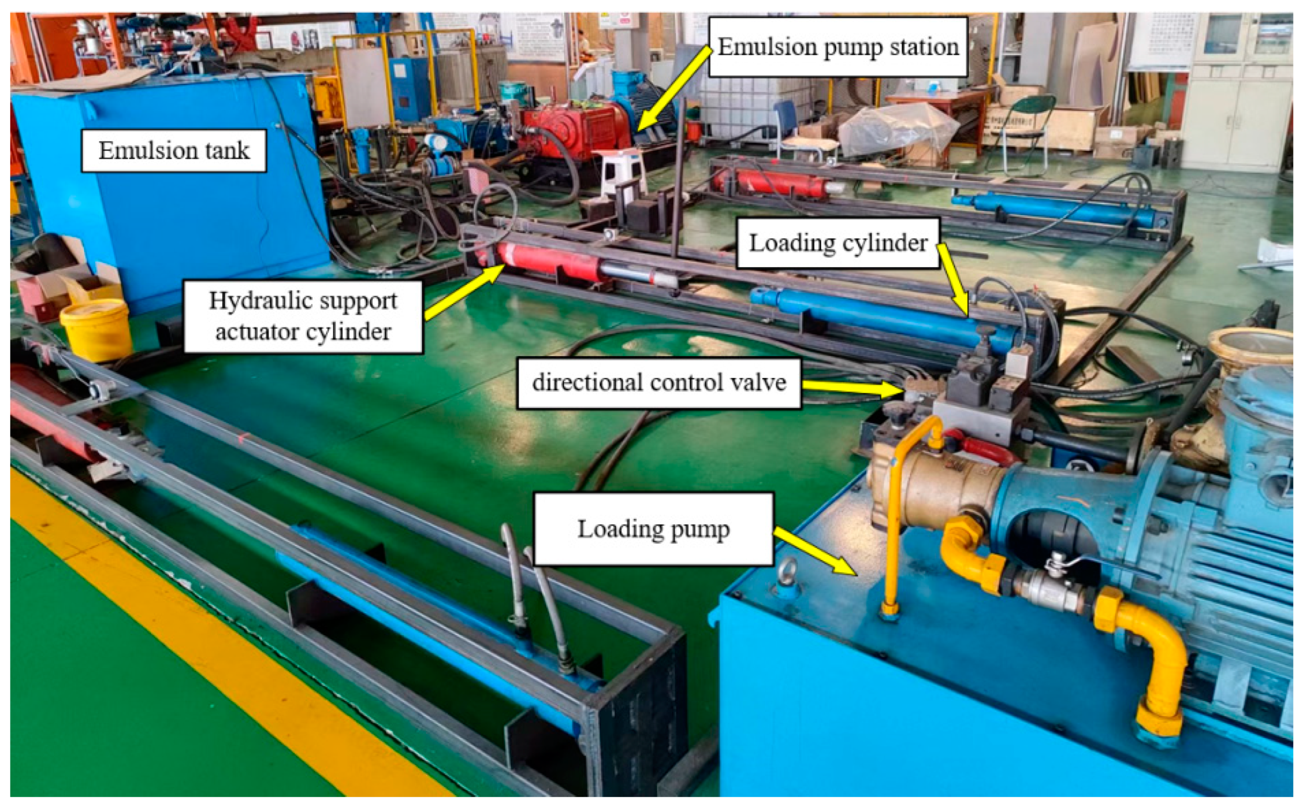
Figure 1. The experimental platform.
Actuators 13 00247 g001
Figure 2. Diagram of the experimental platform.
Actuators 13 00247 g002
Figure 3. Co-simulation model of steady-pressure fluid supply.
Actuators 13 00247 g003
Figure 4. Comparison of system pressure between simulation and experimental results.
Actuators 13 00247 g004
Figure 5. Curve of measured pressure data.
Actuators 13 00247 g005
Figure 6. Pressure curve of steady-pressure fluid supply process.
Actuators 13 00247 g006
Figure 7. Combined design scheme of optimal flow.
Actuators 13 00247 g007
Figure 8. The structure of the GRNN model for predicting the optimal Qp.
Actuators 13 00247 g008
Figure 9. Comparisons between the predicted data and the training data.
Actuators 13 00247 g009
Figure 10. Comparisons between the predicted data with the testing data.
Actuators 13 00247 g010
Figure 11. The flowchart of the online updating control approach.
Actuators 13 00247 g011
Figure 12. Pressure fluctuation curve of rated fluid supply scheme.
Actuators 13 00247 g012
Figure 13. Pressure curve of steady-pressure fluid supply scheme.
Actuators 13 00247 g013
Figure 14. Load signals of the raising and descending stage.
Actuators 13 00247 g014
Figure 15. Online updating steady-pressure fluid supply pressure curve.
Actuators 13 00247 g015
Figure 16. Fluid supply error of online updating.
Actuators 13 00247 g016
Figure 17. Pressure curve for multiple online updating.
Actuators 13 00247 g017
Figure 18. Pressure curve of steady-pressure fluid supply experiment.
Actuators 13 00247 g018
Table 1. Parameters of the experimental platform.
NameParameterValueUnits
EmulsionDensity998kg/m3
Emulsion pumpFlow200/80L/min
Energy accumulatorCapacity20L
Loading cylinderamount3/
Cylinder/rod diameter160/105mm
Column cylinderamount2/
Cylinder/rod diameter110/80mm
Pushing cylinderamount1/
Cylinder/rod diameter110/80mm
Disclaimer/Publisher’s Note: The statements, opinions and data contained in all publications are solely those of the individual author(s) and contributor(s) and not of MDPI and/or the editor(s). MDPI and/or the editor(s) disclaim responsibility for any injury to people or property resulting from any ideas, methods, instructions or products referred to in the content.