Abstract
In-wheel motor vehicles are gaining attention as a new type of electric vehicle due to their efficient power units located inside each wheel hub. However, they are more susceptible to wheel resonance due to the increase in unsprung mass caused by the weight of the motor. This can result in both decreased ride comfort and driving stability. To resolve this issue, in this study, we aim to apply an optimal switching controller with a semi-active actuator—a magnetorheological (MR) damper. For the implementation of the optimal switching controller, road type classification is also carried out. An acceleration sensor is used for the road type classification, and the control logics include a ride comfort controller (the linear quadratic regulator (LQR_Paved Road)) and a wheel motion controller (LQR_Off Road) for improved driving stability. For paved roads, the LQR_Paved Road control input is applied to the MR damper. However, if a road type prone to wheel resonance is detected, the control logic switches to the LQR_Off Road. During the transition, a weighted average of both the LQR_Paved Road and LQR_Off Road control input is applied to the actuator. Computer simulations are performed to evaluate the vibration control performance, including the ride comfort and driving stability on various road profiles.
1. Introduction
A suspension control system design focuses on two main objectives: ensuring a comfortable ride and maintaining driving stability. To evaluate a suspension system in terms of these objectives, three measures are commonly used: the vertical acceleration of the sprung mass, suspension stroke, and tire deflection [1]. The vertical acceleration of the sprung mass is considered the most important measure for evaluating ride comfort and is assessed using the international standard ISO 2631-1 to determine its effects on passengers [2,3]. Driving stability is assessed using the suspension stroke and tire deflection. The relationship between the two objectives and the three measures has been well summarized in the literature [4,5]. Ride comfort is related to the motion of the sprung mass, whereas driving stability is related to the motion of unsprung mass. However, achieving good ride comfort and driving stability simultaneously is challenging. Therefore, most studies have focused on the weight for adjusting the objective function or selecting the performance objective. Numerous controller design methodologies, including the linear quadratic regulator (LQR) [6], LQ static control [7,8], H∞ control [9,10], fuzzy control [11,12], adaptive control [13,14], back-stepping control [15,16], and model predictive control (MPC) [17,18], have been proposed and applied to vehicle suspension systems.
The control target of this study is an in-wheel motor vehicle, that is, a vehicle with the motor and power engine of an electric vehicle that can be reduced in size and embedded in each wheel to compensate for the narrow interior space. This is one of the disadvantages of existing internal combustion engine vehicles. This is beneficial because modern vehicles have become multipurpose with recent developments in autonomous driving technology. Because these in-wheel motor vehicles offer the advantages of improved acceleration and climbing ability compared to existing vehicles while enabling free steering, many studies have been conducted on them [19,20,21].
Compared to conventional vehicles, these in-wheel motor vehicles offer several advantages: the reduction in drivetrain complexity, the reduction in noise due to the drive hub with no chains or gears, and simplicity of the suspension geometry because there is no need to accommodate a shaft drive into the swing arm. However, there are some disadvantages of in-wheel motor vehicles: a higher unsprung mass leads to poor suspension performance, such as low ride comfort and vehicle stability, and hub motors often have anti-torque arms to remove and larger axle bolts. Therefore, an appropriate control strategy needs to be developed to enhance both ride comfort and vehicle stability. To compare the dynamic characteristics of in-wheel and normal vehicles, the frequency response function is shown in Figure 1. It is clearly seen in the figure that the resonance frequency for the sprung mass at 1 Hz is almost the same between normal and in-wheel motor vehicles. However, a considerable difference occurs close to the resonance frequency of the unsprung mass. This is because the weight of unsprung mass is increased, and hence, the resonance frequency value for the unsprung mass is reduced, as given by Equation (1). Wheel resonance can occur due to critical rotational speeds of the vehicle shafts and the spatial frequency of the road profile. When the magnitude of the resonance frequency of the unsprung mass is reduced, it can increase the chance of wheel resonance due to the road profile. This is because the rotational speed of the vehicle shaft is bigger than the spatial frequency of the road profile.
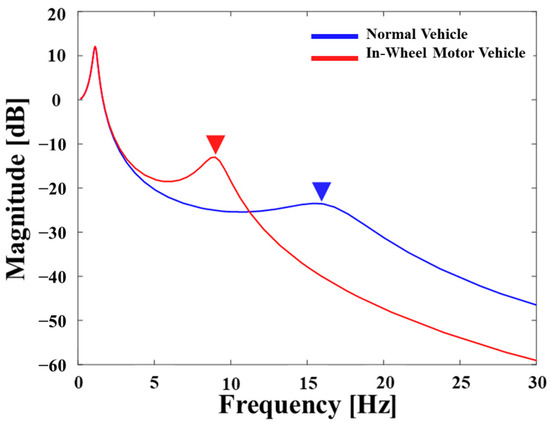
Figure 1.
Dynamic characteristics of the vehicle suspension system.
As is evident, a shift in the resonance frequency towards lower values is undesirable. In general road configurations, the roughness of the road surface can increase the wheel motion, thereby compromising vehicle stability and ride comfort [22,23]. The increase in wheel mass, particularly in the range of 4–9 Hz, wherein humans are sensitive to vertical acceleration, induces higher vibrations [23]. The Grzegorz Slaski research team from Poznan University conducted real-world tests to demonstrate the degradation of ride comfort in vehicles with increased wheel mass owing to the installation of in-wheel motors. The results indicated that an increase in wheel mass adversely affected ride comfort and driving stability [23]. Therefore, ride comfort and driving stability may deteriorate owing to the wheel mass, which may be fatal to passengers and could severely impact vehicles. Thus, this study proposes the use of a road type classification logic designed using data-driven artificial intelligence algorithms. This logic aims to distinguish between off-roads, which exhibit a high likelihood of compromised driving stability, and paved roads, where ride comfort is the primary concern. Based on this classification, separate control strategies are applied depending on dynamic characteristics, which are different based on the ratio of the sprung mass to the unsprung mass.
Despite the significant issues in this work, studies on the vibration systems featured in in-wheel motor vehicles, such as electric cars, are considerably rare compared to the conventional suspension system in which the sprung mass is much higher than the unsprung mass. Consequently, the main technical contribution of this work is to evaluate the vibration control performance of in-wheel motor vehicles in which the weighting of the unsprung mass is crucial for both the ride comfort and steering stability. In order to achieve this goal, an optimal linear quadratic regulator (LQR) controller is formulated and modified to switch between paved roads and off-roads, respectively. In addition, in order to reflect real environmental conditions, road classification is carried out in this work using both long short-term memory (LSTM) and the Kalman filter to estimate the road roughness, and hence, achieve high accuracy through an artificial neural network with a multi-input–single output (MISO) system structure. The proposed control strategy is then simulated using MATLAB/Simulink, and the classified road type and vibration control performances with the sprung mass and unsprung mass are evaluated and presented in both the frequency and time domains.
2. Controller Design
2.1. Controller for Car Body and Wheels
In this work, the suspension controller is designed based on a 2-degrees of freedom (2-DOF) quarter-car model [11,12]. There are various models available for the dynamic analysis of vehicles, ranging from simpler to more complex structures. Simple lower-order models with lumped parameters are often used to analyze vertical dynamics [11]. Specifically, quarter-car models exclusively depict the vertical motion of the chassis. In Figure 2, a suspension system with two degrees of freedom (2-DOF) is illustrated. This system consists of two interconnected subsystems, each featuring a spring and a viscous damper mounted on a mass-containing structure. To represent the vertical motion, sprung mass (ms) and unsprung mass (mu) are used, respectively. The weight of the unsprung mass includes those of the wheels, tires, brakes, hub motors, etc. Meanwhile, the sprung mass includes those of the chassis, car body, interior, passenger, and cargo. The unsprung mass of a typical vehicle is approximately 40 kg [11]. However, in-wheel motor vehicles exhibit a significant increase in unsprung mass due to the structural necessities including the mounting system for the motor rotor and stator, steering mechanism, and suspension components connected directly to the wheel.
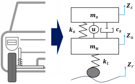
Figure 2.
A 2-DOF quarter-car suspension model of the in-wheel motor vehicle.
The dynamic variables zs and zu are the vertical displacements of ms and mu, respectively. The actuator position is parallel to the spring and damper, as shown in Figure 2. The quarter-car model disturbance zr represents the road profile. The damper, shown in Figure 2, is a semi-active actuator with a specific damping curve. The damper is considered linear and has a constant damping coefficient (cs), spring stiffness (ks), and tire stiffness () during the controller design stage. From Figure 2, the governing equation of the quarter-car model for an in-wheel motor vehicle can be derived using Equation (2), and the state-space model is expressed as shown in Equation (3).
Active actuators such as hydraulic, electromagnetic, and electromechanical are commonly used in commercial vehicles [1]. However, they incur high power consumption and contain cost-intensive components. By contrast, semi-active actuators such as hydraulic shock absorbers, magnetorheological (MR) dampers [24,25], electrorheological (ER) dampers [26,27], and electromagnetic dampers [28] offer lower power requirements, high stability, and more compact form. However, they can only generate force within specific velocity-force quadrants. Both active and semi-active actuators offer the advantage of an independent force direction from the velocity sign. However, semi-active actuators, particularly MR dampers, are preferred owing to their energy efficiency. In this work, a semi-active MR actuator is adopted to achieve the required damping force based on the flowing dynamic conditions.
The semi-active condition expressed by Equation (4) is a condition to reflect the physical properties of the MR damper. Active suspension systems offer control capabilities across all four quadrants, whereas semi-active suspension systems are restricted to the first and third quadrants. In general, the active suspension systems provide greater efficacy in mitigating vibrations. However, due to drawbacks such as the large size of the device and high cost, semi-active suspension systems have been more commonly studied and implemented in real vehicles recently [29]
The parameters of the in-wheel motor vehicles are listed in Table 1. To represent the in-wheel motor vehicle, the weight of the unsprung mass was selected as 100.908 kg, and the other values were adopted from the mid-size SUV (Sports Utility Vehicle) of IPG CarMaker SW [30,31]. By using this vehicle model, the typical control system is displayed in Figure 3. The MR damper as an actuator with control logic generates the control force to control the dynamic motion of the vehicle that will be transmitted to the vehicle. In general, ride comfort and driving stability are mutual trade-offs, making it difficult to achieve both simultaneously. Therefore, it is common to formulate a control strategy to enhance physical performance according to each specific objective. To address this issue, this study proposed a strategy wherein the LQR_Paved Road and LQR_Off Road controllers were dynamically selected based on the situation, as illustrated in Figure 4. The road type was classified by the LSTM algorithm. Then, the proper controller and control input were calculated. This approach aimed to achieve the simultaneous control of ride comfort and wheel resonance by transitioning between two switching controllers as follows.

Table 1.
Parameter values of the 2-DOF quarter-car.

Figure 3.
Typical control flowchart.

Figure 4.
Control flowchart proposed in this work.
The LQR_Paved Road controller for the vehicle suspension system contains an objective function, of Equation (5), which uses weight values (ρi) to adjust the importance of each term. As shown in this equation, the acceleration of the sprung mass was included to increase ride comfort. These weight values were determined using Bryson’s rule, which sets the maximum allowable value for each term to select the weight values, as expressed in Equation (6). The first term of the objective function is the acceleration of the sprung mass, which is associated with ride comfort. It is assigned a lower weight value (η1) than the other terms (ηi) such as suspension stroke and tire deflection, which are associated with road adhesion and cornering performance and given higher weight values (η2 and η3). The weights (η) used for each controller are summarized in Table 2. Weighting matrices Q, N, and R were defined based on these weight values. The LQR_Paved Road controller used full-state feedback to minimize J, and the gain matrix was calculated using the Riccati equation with the system matrices (A, B, Q, N, and R). Inconsequently, a four-element K matrix corresponding to the number of state variables was obtained, as shown in Equation (7). In addition, to focus on the motion of the wheel, the LQR_Off Road controller was designed based on the objective function defined in Equation (8). Compared to Equation (5), the stroke was replaced with the velocity of the wheel. Table 2 lists the chosen weight values and calculated gain matrix for LQR_Paved Road and LQR_Off Road. The control gains for LQR_Paved Road() and LQR_Off Road(), which were calculated using Equations (5)–(8), are expressed as Equation (9). To enhance ride comfort, the LQR_Paved Road controller was designed with a focus on optimizing the movement of the sprung mass. Consequently, it may be less robust in handling the movement of the unsprung mass. Conversely, the LQR_Off Road controller, optimized for unsprung mass movement, may encounter challenges in simultaneously optimizing the ride comfort.

Table 2.
Maximum allowable values in LQ objective function.
2.2. Concept of Controller for In-Wheel Motor Vehicle Control Using Road Type Classification Logic
The controllers described in Section 2.1 differ in the required moment depending on the driving situation. As an in-wheel vehicle requires wheel motion control for driving stability, this study proposes a decision logic to detect road types. The concept of the proposed control logic involves switching between a ride-comfort-oriented controller (LQR_Paved Road) and a wheel-motion-control-oriented controller (LQR_Off Road) to perform control. If the road type classification logic detects that based on the current road situation, the comfort and stability of the passengers are more important than the improvement in driving stability (such as on a paved road). In this way, the LQR_Paved Road controller is used as the control logic to apply commands to the actuator. Conversely, in the case of off-roading, wheel motion control through improvement in driving stability is more prioritized than riding comfort. Therefore, the LQR_Paved Road control logic is switched to the LQR_Off Road control logic to secure the driving stability of the vehicle. This is intended to improve both the ride comfort and driving stability of an in-wheel vehicle.
3. Road Type Classification Based on LSTM
There are various road type classification logic methods for controller switching [32,33]. Harikrishnan et al. used the three-axial acceleration sensor of a smartphone to determine potholes and bumps using a rule-based method in low-speed (15–20 km/h) vehicles and reported accuracies of at least 65.2–98.4% [32]. Menegazzo et al. performed classification (dirt, cobblestone, and asphalt) based on artificial neural network algorithms, such as convolutional neural networks (CNNs) and LSTM, using various sensors, including the global positioning system (GPS) and camera sensors. The accuracy was reported as 95.56% [33]. The LSTM-based classification method exhibits high accuracy through an artificial neural network with a multi-input–single output (MISO) structure. Thus, using various sensor values as the input layer data results in a positive effect on classification accuracy [34]. However, securing a large amount of sensor data while ignoring the relationship between the input sensor data and decision labels increases the system design costs, the dimensions, and the complexity of artificial neural networks. Therefore, in this study, as shown in Figure 5, an LSTM-based road type classifier was developed using only two inputs: the prediction results and the acceleration sensor of the sprung and unsprung masses, following the estimation of the profile of the road using a Kalman filter to estimate the road roughness using two acceleration sensors and one damper relative displacement sensor.

Figure 5.
Road type classification based on LSTM and Kalman filter.
This study developed a discrete Kalman with unknown input (DKF-UI) using a tire normal force estimator [35]. The unknown road roughness values applied to the wheels of the quarter-car model were estimated using the DKF-UI model, and the road profile was estimated. Equations (10)–(14) represent the main estimation process of the DKF-UI algorithm. For more detailed information, please refer to our previous studies [35,36].
The internal structure of the LSTM model is shown in Figure 6. It has a circular structure similar to that of the recurrent neural network (RNN) and a complex internal structure. The LSTM cell comprises three gates and one memory cell, where xt denotes the input, ht denotes the output at time t, ht−1 is the output immediately before t, and l denotes the order of the LSTM cells. The data flow is depicted in Figure 6 by arrows, and the operations between the matrix members are indicated by circles. The entire dataset was divided by window size to obtain the number of cells represented by n.
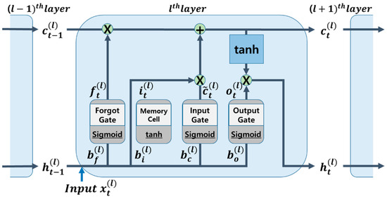
Figure 6.
Internal structure of LSTM model.
- -
- Initialization of parameter at
- -
- Prediction step
- -
- Kalman gain calculation
- -
- Unknown input estimation step
- -
- Correction step
The forward propagation process can be expressed as follows [36]:
- -
- Forget gate
- -
- Input gate and new memory
- -
- Output gate
- -
- Cell state and hidden state
The amount of memory cell content retained can be altered using a forget gate. The forget gate employs a sigmoid function. The weight is multiplied by the output value from the previous time, enters the LSTM cell at the present moment, and bias is then applied. The input to the sigmoid function is the output value.
In this case, the data move on to the following step after being multiplied by ct-1 while passing through the sigmoid activation function. At time , the input gate modifies the amount of output that is mirrored in the memory cell. Subsequently, it becomes a new memory and is added to the memory cell if it successfully completes its activation function. The new memory is then multiplied by and passes through the input gate to create . The newly formed is delivered to the following LSTM cell and contains only the required information: the final step involves choosing the export output. The value of this output is filtered based on the cell status. First, it selects the portion of to output as the input data for the sigmoid layer. The output of the previously calculated sigmoid gate is multiplied by before being transmitted through the tanh layer. Consequently, output of the exported data only includes the desired section. As shown in Figure 7, the layers used include the sequence input, bi-LSTM, fully connected, softmax, and classification layers, which were designed to classify road types into 200 hidden units.
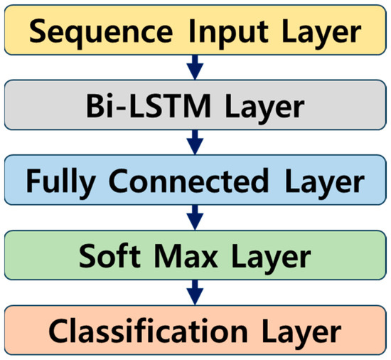
Figure 7.
LSTM layers.
Table 3 lists the optimal hyperparameters used to train the LSTM artificial neural network. The corresponding hyperparameters were selected through trial and error. In this study, the data used for the LSTM training were generated by designing random roads based on the ISO 8608 standard [37] and were categorized into five grades (A, B, C, D, and E). The computation of the LSTM model is run under NVIDIA DGX STATION (Future Automotive Intelligent Electronics Core Technology Center, Republic of Korea). The road roughness increased from A-class to E-class roads. In particular, the E-class road exhibited a level of roughness comparable to that of unpaved roads. Therefore, to differentiate the roads, A-, B-, and C-class roads were labeled as paved roads, emphasizing ride-comfort-oriented control, whereas D-class and E-class roads were labeled for wheel-motion-oriented control, resembling unpaved roads.. The descriptions of these labels are summarized in Table 4. The road classifier, developed after training on the given data, was applied to roads that were a mixture of wavy roads with amplitudes of 0.02 m and frequencies of 1, 9, and 15 Hz, combined with the roads used for training, to assess its performance and robustness.

Table 3.
Selected hyperparameters for LSTM model.

Table 4.
Labels for LSTM model.
Table 5 presents the results of the artificial neural network derived from the confusion matrices for road type classification on each validation dataset with optimal hyperparameters in terms of , , and score. These metrics are expressed as follows:

Table 5.
Road classification performance.
is the ratio of what is actually true to what the neural network model predicts to be true and is also referred to as the positive predictive value. is the ratio of what the model predicts to be true to what is true and is also referred to as the hit rate. The harmonic average of these two indicators is the indicator. The higher the number of these three indicators, the better the result. The average of the three performance indicators for the LSTM artificial neural network used in this study was 91.10%, which is good compared with previous studies. As summarized in Table 5, the results indicated that combining frequencies that are lower (1 Hz) or higher (15 Hz) than the wheel resonance frequency (9 Hz) yielded consistently good outcomes. This observation was true even when mixing frequencies on random roads without a specific frequency. Thus, the robustness of the designed LSTM network, independent of the presence or absence of specific frequency components, was appropriately demonstrated. Among these results, the confusion matrix for the road mixture with a wavy road wheel resonance frequency (9 Hz), which is representative and has the most significant impact on the target vehicle in this study, is shown in Figure 8.
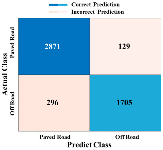
Figure 8.
Confusion matrix for random road + 9 Hz wavy road.
The LSTM model, which is capable of learning the periodicity of time-series data, demonstrated superior performance in effectively learning the various frequencies present on random roads. Therefore, it was inferred that the model performed well even on roads composed of a specific frequency of wavy road combinations.
4. Control Results and Discussions
The LSTM-based road type classification and control logic were designed and analyzed using MATLAB and Simulink. Although the LSTM-based road type classification logic exhibited high accuracy, controller switching can cause a chattering problem in the control input. Chattering is an undesirable phenomenon characterized by infinitely fast switching, which may cause equipment damage in real vehicle systems. To avoid its occurrence, many solutions such as integration, moving average filter, and saturation function [38,39] have been reported. A chattering-free strategy based on a moving average filter was applied to the proposed control architecture. In this study, we also utilized a moving average filter to prevent excessive chattering and enhance the control performance. To improve the ride comfort and driving stability of in-wheel motor vehicles, road conditions were determined through LSTM, and the control was performed by switching the controller based on the determined road and applying it to the actuator.
The overall flow of the integrated control logic is shown in Figure 4, as explained earlier. After completing the training, the LSTM network used sensor data and Kalman filter estimates to assess the wheel resonance. Based on this determination, an appropriate controller was selected to perform the control. As described in Section 2.2, the controller conversion applied the LQR_Paved Road controller to paved roads, and the LQR_Paved Road control logic was switched to the LQR_Off Road control logic to secure driving stability and ride comfort. This was intended to improve both the ride comfort and driving stability of the in-wheel vehicle. After the control tests, the results were evaluated using various criteria. First, the ride comfort control result was evaluated according to the ISO 2631_Wk standard [2] to numerically express the degree of vibration felt by an occupant while sitting because vertical vibration vibrates throughout the body, which is derived based on the acceleration of the sprung mass. Driving stability was evaluated based on tire deflection. Tire deflection is a numerical value indicating the degree of contact of the wheel with the road, which is calculated as the RMS of the difference between the displacement of the road profile and the unsprung mass. In the case of ISO 2631_Wk (ride comfort) and tire deflection results derived after performing the control, the smaller the number, the better the result that could be obtained.
After performing the controller on the road type classification and control strategy, the results were interpreted based on various criteria. Results without control input, control results for LQR_Paved Road and LQR_Off Road, and control results with road type classification and switching controller were obtained and presented. In addition, the roads used in the simulation as shown in Figure 9 were set to select A-, B-, C-, D-, and E-class roads, which could be sequentially applied for 10 s each. The vehicle speed was derived by fixing it at 40 km/h. The control results of switching controllers using Kalman filter-based LSTM classification logic, the results of every single controller (LQR_Paved Road, LQR_Off Road) without road classification logic, and the passive results without control input in the frequency domain are shown in Figure 10a,b. Figure 10a is the result of the acceleration of the vehicle body, and Figure 10b is the result of the displacement of the unsprung mass. With these results, it is possible to confirm the characteristics of the ride comfort and driving stability of each controller. As can be seen from Figure 10a,b, all results showed better performance than the passive result of not performing control. This means that the vehicle modeling and design of all controllers proceeded as intended. However, LQR_Paved Road occasionally exhibits inferiority to the passive system in unsprung mass displacement (Figure 10b), being 0.53% worse. Additionally, LQR_Off Road exhibits a 4.53% deterioration in sprung mass acceleration compared to the passive system, as shown in Figure 10a. Accordingly, the switch control logic results showed plainly excellent overall vibration control results.
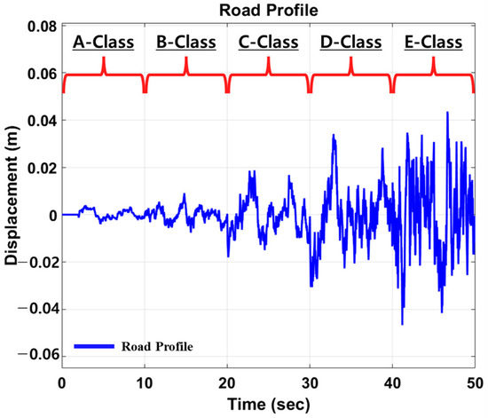
Figure 9.
Road profile used for simulation with MATLAB/Simulink.
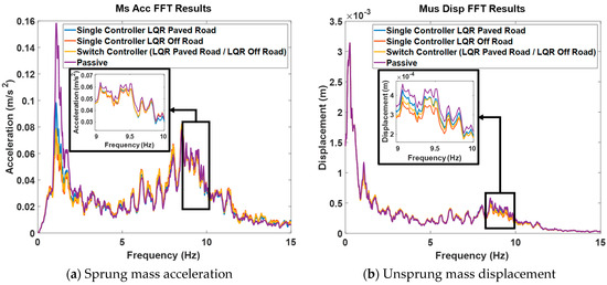
Figure 10.
Control results in frequency domain.
Based on the control characteristics of the LQR_Paved Road and LQR_Off Road controllers, an integrated control logic using switching logic and road type classification was designed to enhance the control performance. This encompassed both ride comfort and wheel motion. Typically, the LQR_Paved Road control is performed mainly for riding comfort, and the road type is classified using an LSTM artificial neural network. The velocity results of sprung mass and unsprung mass for the control logic (Switch) are shown in Figure 11a,b, respectively. As can be seen from the graph, excellent results were shown compared to passive results in most areas, and the effects of classification logic and control logic could be confirmed. Figure 12 shows the result of the control input of each controller. Each controller generated a different input force according to each control characteristic. Furthermore, the force and control performance were not proportional. Nonetheless, as the input force was smaller, the energy efficiency was better because the control was performed with a smaller force. As a result, it was confirmed that the LQR_Paved Road controller had less energy consumption than the LQR_Off Road controller. For the Switch control logic, which performs control by combining these controllers, it displayed the median value of the input force from the two controllers. This indicates that the Switch control logic is an efficient and satisfying performance controller in terms of energy consumption. Table 6 presents the results of each controller. Because ride comfort is related to the acceleration of the car body and tire deflection is related to the displacement of the wheel, all control results related to ride comfort and steering stability are presented. Therefore, when using a single controller, the overall ride comfort and wheel motion performance under various road conditions were not consistently favorable, depending on the characteristics of the controller. However, when the results of this study were applied with a switching logic that included a filter, positive outcomes were achieved for both ride comfort and driving stability under all road conditions.
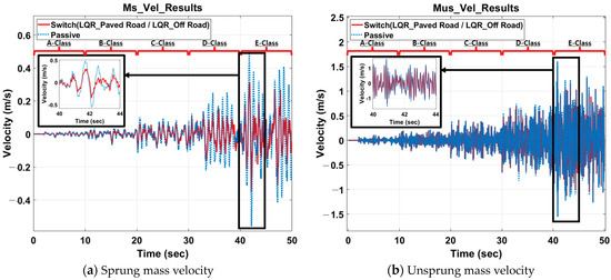
Figure 11.
Control results in time domain.
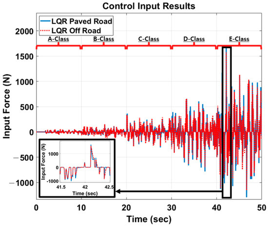
Figure 12.
Control input results of each controller.

Table 6.
Control results according to control type.
In terms of ride comfort, all controllers exhibited improvements compared to the passive system. Among them, the most notable outcome was observed with the LQR_Paved Road controller, showing a 5.8% reduction compared to the passive system. The Switch controller also demonstrated results closely resembling those of the LQR_Paved Road controller. Particularly noteworthy is the observation that the LQR_Off Road controller achieved a 3.08% reduction compared to the passive system. Therefore, in the context of ride comfort-oriented control, the Switch controller proved to be superior to the wheel-motion-centric controller (LQR_Off Road). In terms of vehicle stability, all controllers exhibited improvements compared to the passive system. Among them, the LQR_Off Road controller demonstrated a 6.25% enhancement, while the Switch controller showed a 4.17% improvement compared to the passive system. Furthermore, the vehicle stability results of the Switch controller surpassed those of the ride comfort-oriented controller, LQR_Paved Road. This signifies that the Switch controller outperforms the other control logics and passive controller in all scenarios (ride comfort and vehicle stability). Specifically, for ride comfort on paved roads, it surpasses LQR_Off Road by 1.76%, and for wheel motion control on paved roads, it outperforms LQR_Paved Road by 2.13%. Therefore, the optimal switching control logic proposed in this study has been validated for enhancement of the robust vibration control performances across various road conditions.
5. Conclusions
This study designed an integrated control logic for improving the ride comfort and driving stability of in-wheel motor vehicles using an LSTM-based road type classification and control-mode switching logic according to the road type. A quarter-car model was constructed based on an in-wheel motor vehicle, and state-space equations were derived. LQR_Paved Road and LQR_Off Road controllers were designed based on MR semi-active actuators. The control-mode switching logic was designed using these controllers, and a road type classification logic with an accuracy of 91.10% was designed. Consequently, the ride comfort and driving stability under various road profiles were evaluated. Through this, this study examined the control characteristics of each controller and developed a logic to determine when ride comfort-oriented or wheel motion-oriented control is needed, and it designed a controller that can improve driving stability and improve ride comfort compared to passive by switching the controller.
It is finally noted that the development of a more advanced LSTM neural network to classify road classes needs to be further explored according to road roughness and fuzzy control logic that assigns different weights to controllers based on road classes. Furthermore, in order to assess the practical feasibility of the proposed control strategy, an experimental realization of the quarter-car should be carried out followed by a full-car system implementation by CarMaker in the near future.
Author Contributions
S.-B.C. takes the primary responsibility for this research as the principal investigator and drafted the manuscript. Y.-J.K. contributed to the algorithm and writing of the manuscript; Y.S. and S.C. contributed to the formal analysis; J.-S.O. contributed to the investigation and writing—review and editing. All authors have read and agreed to the published version of the manuscript.
Funding
This result was partially supported by the Research Program through Hyundai Motor Group and “Regional Innovation Strategy (RIS)” through the National Research Foundation of Korea (NRF) funded by the Ministry of Education (MOE) (2021RIS-004).
Data Availability Statement
The data used to support the findings of this study are included within the article.
Conflicts of Interest
Y.S. and S.C. are employed by Hyundai Motor Company. The remaining authors declare that the research was conducted in the absence of any commercial or financial relationships that could be construed as a potential conflict of interest.
References
- Tseng, H.E.; Hrovat, D. State of the art survey: Active and semi-active suspension control. Veh. Syst. Dyn. 2015, 53, 1034–1062. [Google Scholar] [CrossRef]
- ISO 2631-1; Mechanical Vibration and Shock—Evaluation of Human Exposure to Whole-Body Vibration—Part 1: General Requirements. International Organization for Standardization: Geneva, Switzerland, 1997.
- Rimell, A.N.; Neil, J.M. Design of digital filters for frequency weightings required for risk assessments of workers exposed to vibration. Ind. Health 2007, 45, 512–519. [Google Scholar] [CrossRef]
- Tseng, T.; Hrovat, D. Some characteristics of optimal vehicle suspensions based on quarter-car models. In Proceedings of the 29th IEEE Conference on Decision and Control, Honolulu, HI, USA, 5–7 December 1990; pp. 2232–2237. [Google Scholar]
- Hrovat, D. Survey of advanced suspension developments and related optimal control applications. Automatica 1997, 33, 1781–1817. [Google Scholar] [CrossRef]
- Attia, T.; Vamvoudakis, K.G.; Kochersberger, K.; Bird, J.; Furukawa, T. Simultaneous dynamic system estimation and optimal control of vehicle active suspension. Veh. Syst. Dyn. 2019, 57, 1467–1493. [Google Scholar] [CrossRef]
- Park, M.; Yim, S. Design of static output feedback and structured controllers for active suspension with quarter-car model. Energies 2021, 14, 8231. [Google Scholar] [CrossRef]
- Park, M.; Yim, S. Comparative Study on Effects of Input Configurations of Linear Quadratic Controller on Path Tracking Performance under Low Friction Condition. Actuators 2023, 12, 153. [Google Scholar] [CrossRef]
- Yang, M.; Peng, C.; Li, G.; Wang, Y.; Ma, S. Event-triggered H∞ control for active semi-vehicle suspension system with communication constraints. Inf. Sci. 2019, 486, 101–113. [Google Scholar] [CrossRef]
- Zhang, Y.; Liu, M.; Zhang, C. Robust fault-tolerant H∞ output feedback control of active suspension and dynamic vibration absorber with finite-frequency constraint. IET Intell. Transp. Syst. 2020, 14, 1935–1945. [Google Scholar] [CrossRef]
- Du, H.; Zhang, N. Fuzzy control for nonlinear uncertain electrohydraulic active suspensions with input constraint. IEEE Trans. Fuzzy Syst. 2008, 17, 343–356. [Google Scholar]
- Gad, A.S.; El-Zoghby, H.; Oraby, W.; El-Demerdash, S.M. Application of a Preview Control with an MR Damper Model Using Genetic Algorithm in Semi-Active Automobile Suspension; Technical Paper No. 2019-01-5006; SAE: Warrendale, PA, USA, 2019. [Google Scholar]
- Huang, Y.; Na, J.; Wu, X.; Liu, X.; Guo, Y. Adaptive control of nonlinear uncertain active suspension systems with prescribed performance. ISA Trans. 2015, 54, 145–155. [Google Scholar] [CrossRef]
- Pan, H.; Sun, W.; Jing, X.; Gao, H.; Yao, J. Adaptive tracking control for active suspension systems with non-ideal actuators. J. Sound Vibrat. 2017, 399, 2–20. [Google Scholar] [CrossRef]
- Su, X. Master–slave control for active suspension systems with hydraulic actuator dynamics. IEEE Access 2017, 5, 3612–3621. [Google Scholar] [CrossRef]
- Liu, L.; Zhu, C.; Liu, Y.J.; Wang, R.; Tong, S. Performance improvement of active suspension constrained system via neural network identification. IEEE Trans. Neural Netw. Learn. Syst. 2022, 34, 7089–7098. [Google Scholar] [CrossRef] [PubMed]
- Liu, Y.; Zuo, L. Energy-flow-driven (EFD) semi-active suspension control. In Proceedings of the 2014 American Control Conference, Portland, OR, USA, 4–6 June 2014; pp. 2120–2125. [Google Scholar]
- Enders, E.; Burkhard, G.; Munzinger, N. Analysis of the influence of suspension actuator limitations on ride comfort in passenger cars using model predictive control. Actuators 2020, 9, 77. [Google Scholar] [CrossRef]
- Liu, M.; Gu, F.; Zhang, Y. Ride comfort optimization of in-wheel-motor electric vehicles with in-wheel vibration absorbers. Energies 2017, 10, 1647. [Google Scholar] [CrossRef]
- Savitski, D.; Ivanov, V.; Augsburg, K.; Emmei, T.; Fuse, H.; Fujimoto, H.; Fridman, L.M. Wheel slip control for the electric vehicle with in-wheel motors: Variable structure and sliding mode methods. IEEE Trans. Ind. Electron. 2019, 67, 8535–8544. [Google Scholar] [CrossRef]
- Luo, Y.; Tan, D. Study on the dynamics of the in-wheel motor system. IEEE Trans. Veh. Technol. 2012, 61, 3510–3518. [Google Scholar]
- Shao, X.; Naghdy, F.; Du, H. Reliable fuzzy H∞ control for active suspension of in-wheel motor driven electric vehicles with dynamic damping. Mech. Syst. Signal Process. 2017, 87, 365–383. [Google Scholar] [CrossRef]
- Ślaski, G.; Gudra, A.; Borowicz, A. Analysis of the influence of additional unsprung mass of in-wheel motors on the comfort and safety of a passenger car. Arch. Motoryz. 2014, 65, 51–64. [Google Scholar]
- Choi, S.B.; Lee, H.S.; Park, Y.P. H8 control performance of a full-vehicle suspension featuring magnetorheological dampers. Veh. Syst. Dyn. 2002, 38, 341–360. [Google Scholar] [CrossRef]
- Sohn, J.W.; Oh, J.S.; Choi, S.B. Design and novel type of a magnetorheological damper featuring piston bypass hole. Smart Mater. Struct. 2015, 24, 035013. [Google Scholar] [CrossRef]
- Tang, X.; Ning, D.; Du, H.; Li, W.; Wen, W. Takagi-Sugeno fuzzy model-based semi-active control for the seat suspension with an electrorheological damper. IEEE Access 2020, 8, 98027–98037. [Google Scholar] [CrossRef]
- Pham, T.P.; Sename, O.; Dugard, L. Real-time damper force estimation of vehicle electrorheological suspension: A nonlinear parameter varying approach. IFAC-PapersOnline 2019, 52, 94–99. [Google Scholar] [CrossRef]
- Kawamoto, Y.; Suda, Y.; Inoue, H.; Kondo, T. Modeling of electromagnetic damper for automobile suspension. J. Syst. Des. Dyn. 2007, 1, 524–535. [Google Scholar] [CrossRef]
- Gustafsson, A.; Sjögren, A. Neural Network Controller for Semi-Active Suspension Systems with Road Preview. Master’s Thesis, Master Programme Systems, Control and Mechatronics. Chalmers University of Technology, Gothenburg, Sweden, 2019. [Google Scholar]
- Ricciardi, V.; Ivanov, V.; Dhaens, M.; Vandersmissen, B.; Geraerts, M.; Savitski, D.; Augsburg, K. Ride blending control for electric vehicles. World Electr. Veh. J. 2019, 10, 36. [Google Scholar] [CrossRef]
- Büyükköprü, M.; Uzunsoy, E.; Mouton, X. Global skyhook and groundhook control of vehicle with semi-active dampers. In Proceedings of the 10th International Automotive Technologies Congress, Virtual Congress, 6–7 September 2021. [Google Scholar]
- Harikrishnan, P.M.; Gopi, V.P. Vehicle vibration signal processing for road surface monitoring. IEEE Sens. J. 2017, 17, 5192–5197. [Google Scholar] [CrossRef]
- Jeferson, M. Road surface type classification based on inertial sensors and machine learning. Comput. Arch. Inform. Numer. Comput. 2021, 103, 2143–2170. [Google Scholar]
- Eichenlaub, T.; Rinderknecht, S. Anticipatory Longitudinal Vehicle Control using a LSTM Prediction Model. In Proceedings of the 2021 IEEE International Intelligent Transportation Systems Conference (ITSC), Indianapolis, IN, USA, 19–22 September 2021; pp. 447–452. [Google Scholar]
- Kim, G.W.; Kang, S.W.; Kim, J.S.; Oh, J.S. Simultaneous estimation of state and unknown road roughness input for vehicle suspension control system based on discrete Kalman filter. Proc. Inst. Mech. Eng. Part D J. Automob. Eng. 2020, 234, 1610–1622. [Google Scholar] [CrossRef]
- Im, S.J.; Oh, J.S.; Kim, G.W. Simultaneous Estimation of Unknown Road Roughness Input and Tire Normal Forces Based on a Long Short-Term Memory Model. IEEE Access 2022, 10, 16655–16669. [Google Scholar] [CrossRef]
- ISO 8608; Mechanical Vibration, Shock. Subcommittee SC2 Measurement, Evaluation of Mechanical Vibration, & Shock as Applied to Machines. Mechanical Vibration–Road Surface Profiles–Reporting of Measured Data. International Organization for Standardization: Geneva, Switzerland, 1995.
- Sumantri, B.; Uchiyama, N.; Sano, S. Least square based sliding mode control for a quad-rotor helicopter and energy saving by chattering reduction. Mech. Syst. Signal Process. 2016, 66, 769–784. [Google Scholar] [CrossRef]
- Savaia, G.; Panzani, G.; Corno, M.; Sinigaglia, A.; Savaresi, S.M. Tracking a reference damping force in a magneto-rheological damper for automotive applications. IFAC-PapersOnLine 2020, 53, 14318–14323. [Google Scholar] [CrossRef]
Disclaimer/Publisher’s Note: The statements, opinions and data contained in all publications are solely those of the individual author(s) and contributor(s) and not of MDPI and/or the editor(s). MDPI and/or the editor(s) disclaim responsibility for any injury to people or property resulting from any ideas, methods, instructions or products referred to in the content. |
© 2024 by the authors. Licensee MDPI, Basel, Switzerland. This article is an open access article distributed under the terms and conditions of the Creative Commons Attribution (CC BY) license (https://creativecommons.org/licenses/by/4.0/).