Abstract
To address the challenges of sinking, imbalance, and complex control systems faced by hexapod robots walking on lunar soil, this study develops an umbrella-shaped foot lunar exploration hexapod robot. The overall structure of the robot is designed to mimic the body structure of insects. By incorporating a four-bar linkage mechanism to replace the commonly used naked joints in traditional hexapod robots, the robot reduces the number of degrees of freedom and simplifies control complexity. Additionally, an extension mechanism is added to the robot’s foot, unfolding into an umbrella shape to provide a larger support area, effectively addressing the issue of foot sinking instability during walking. This study adopts and simplifies the Central Pattern Generator (CPG) model to generate stable periodic control signals for the robot’s legs. Precise control of the extension mechanism’s unfolding period is achieved through mapping functions. A joint simulation platform using Solid Works and Matlab is established to analyze the stability of the robot’s walking. Finally, walking experiments are conducted on the prototype, confirming the smooth walking of the lunar exploration hexapod robot. The results indicate that the designed lunar exploration hexapod robot has a reasonable structure, excellent stability in motion, and the CPG control scheme is feasible.
1. Introduction
At present, many countries and space agencies are committed to exploring the Moon. In addition to its valuable resources, studying it also helps to gain a deeper understanding of the basic characteristics of the solar system. Moreover, its position is not affected by the Earth’s ionosphere, making it an ideal location for observing the sun and exoplanets [1,2]. To achieve these goals, one of the key questions is to answer whether there is water on the Moon. There is now considerable evidence that the Moon’s PSRs contain water ice and other preserved volatiles [3,4]. The NASA Artemis program (NASA, 2022a) is also leading a series of missions to search for water ice on the lunar surface and perform ISRU, allowing astronauts to stay on the Moon for a longer time [5,6]. Therefore, exploring the Moon is of great significance. According to the investigation, the surface of the Moon is covered with a layer of loose rock fragments, commonly known as the lunar weathering layer [5]. Through analysis of lunar soil samples, it was found that most of the weathered layer is composed of fine particles, which becomes looser under long-term small collisions and weathering. Therefore, the lunar soil is very soft, and the overall hardness is low. In addition, the surface of the Moon is also covered with various sizes of impact craters, with diameters ranging from a few micrometers to hundreds of kilometers. Most lunar impact craters are circular or elliptical in shape, and the larger the diameter, the deeper the crater is. The interior of the craters usually has complex terrain features [7,8,9].
Faced with numerous complex environments such as loose lunar soil, craters, and meteorites, landing and walking pose great challenges, greatly reducing the safety and feasibility of human tasks. Therefore, the application of robots is essential. So far, all successful lunar rovers have been wheeled robots. However, multiple experiments have shown that legged robots are more suitable for exploring complex terrains. The design and motion of legged robots are inspired and guided by biomechanical principles, and belong to the category of biomimetic robots, which have the characteristics of flexibility and strong adaptability [10,11,12]. They can effectively avoid the compaction resistance caused by the accumulation of substrate material in front of the wheels. Each leg has a discrete support point, and their excellent maneuverability allows legged robots to travel through complex environments without being restricted by wheels or tracks, avoiding being obstructed or trapped in depressions [13,14].
The development process of legged robots can be traced back to the mid-20th century. With the continuous research and improvement of robot technology by scientists and engineers, legged robots have made significant progress in different fields. In the 1960s, significant progress was made in the research of legged robots [15]. Researchers such as Marvin Minsky and Seymour Papert from the Massachusetts Institute of Technology in the United States developed early legged robots such as “Walker” and “Shakey”, which can perform basic walking and obstacle avoidance tasks [16]. In the 1980s, research on legged robots further developed, including more advanced perception technologies and control systems. The Japanese company “Honda” has developed “P2”, a bipedal robot with high stability and human gait simulation [17]. The “Leg Lab” team at Carnegie Mellon University in the United States has developed various bipedal robots for studying gait control and robot stability [18]. Since 2014, Delft University of Technology has been working hard to send the world’s smallest and lightest lunar hexapod robot to the Moon. Its design inspiration comes from cockroaches, which have claw shaped track teeth on their legs and can explore terrain well [19]. Among many legged robots, the most typical is the hexapod robot, which has good overall stability and lower energy costs. Hexapod robots have more support points compared to bipedal and quadruped robots, resulting in a more uniform distribution of weight during movement, reducing the load on individual support points, and being able to adapt to different terrains and tasks by adjusting the support points. They have a higher stability and a lower likelihood of swaying and overturning. On the other hand, although the eight legged robot is relatively stable, its energy efficiency is relatively low [20]. Therefore, hexapod robots have great potential value and can cope with many challenges. The traditional hexapod robot has 18 degrees of freedom, which requires a large number of actuators and high computational power to coordinate the robot’s motion. By reducing drive design, robots can achieve higher power to weight ratios while maintaining high levels of mobility and reduce the complexity of control systems.
By reducing the drive design, the weight of the hexapod robot can be greatly reduced, but to cope with the characteristics of the lunar soil the design of the foot end is also essential. The George Lordos team has conducted various designs for the foot end of on-site reconfigurable robots suitable for extreme lunar terrains. These foot end designs include planar, spherical, and planar–spherical hybrid designs, all of which have undergone support and stability research on uneven weathered terrain and have been prototype designed and tested on artificial snow that simulates the characteristics of the weathered layer. Under the weight of 14 kg, the flat foot end shows the minimum sinking degree. The circular foot tip has better contact and stability on the rock surface [21]. Consequently, when a hexapod robot walks on the Moon, if its foot tip is spherical, it will sink and fall into the lunar soil due to the presence of a weathered layer, resulting in imbalance. If the foot is flat, it will slip when walking to the rock surface due to insufficient contact. If there are too many single leg drive designs, it will lead to an increase in overall mass, complex control, and an increase in failure rate.
In response to the aforementioned challenges, this study developed a lunar exploration hexapod robot with an umbrella-shaped foot end. The stability of motion is defined based on the smoothness of walking and the reduction in stationary or overturning situations. The design of robots aims to solve the problems of sinking and instability during walking. The overall structure was simplified by replacing naked joints with a four-bar linkage mechanism, reducing both control complexity and weight, thereby enhancing the robot’s controllability. An extension mechanism was added to the foot end, refining the control of the single-leg mapping function for precise closure. The design of the umbrella-shaped foot end provides a larger supporting surface effectively distributing the robot’s weight more evenly, reducing pressure on the lunar soil contact, and minimizing the risk of sinking. This enhances the robot’s stability on the lunar surface. The study employed and streamlined a CPG model to generate stable periodic control signals for the robot’s legs. A mapping function was utilized to precisely control the extension mechanism’s deployment period. A collaborative simulation platform using Solid Works and Matlab was established to analyze the stability of the robot’s walking. Finally, prototype walking experiments were conducted, demonstrating the smooth locomotion of the lunar exploration hexapod robot. The results indicate that the developed lunar exploration hexapod robot exhibits a rational structure, good motion stability, and the feasibility of the CPG control approach.
2. Structural Design of a Lunar Exploration Hexapod Robot
2.1. Design of the Bottom Plate of the Lunar Exploration Hexapod Robot
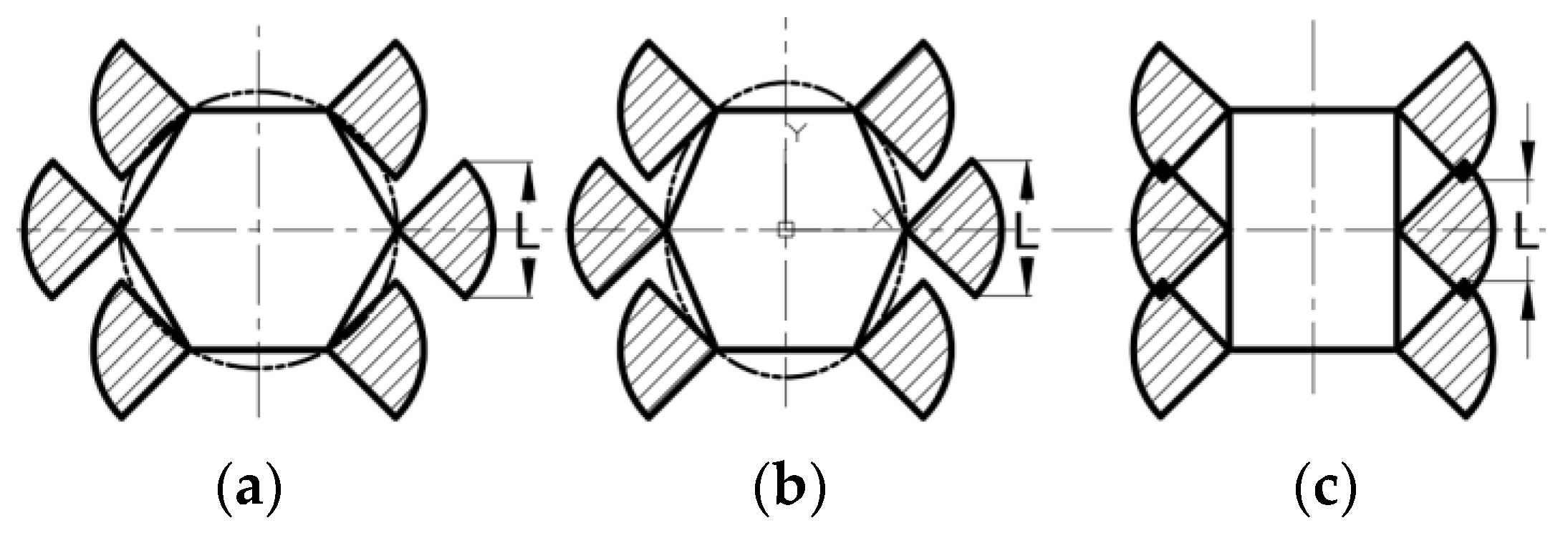
Usually, the arrangement of the legs of a hexapod robot is connected in three layouts: circular, elliptical, and rectangular, as shown in Figure 1. When the swing angle of each leg is the same, the leg needs to sweep over the same size of the sector area, so two factors need to be considered in the design:
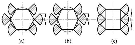
Figure 1.
Three types of bottom plate layouts: (a) Circle; (b) Ellipse; (c) Rectangle.
- (1)
- When moving, the interference between each leg is as follows: the rectangular layout has the highest overlap in the swing range of the legs, while the circular layout has the smallest overlap. This means that while ensuring no interference between adjacent legs, the circular layout has the largest swing space of the legs, followed by the elliptical layout, while the rectangular layout has the smallest overlap.
- (2)
- Effective distance for straight walking: The maximum effective distance that a single leg can walk is L, while ensuring that adjacent legs do not interfere. Figure 1 shows that the step effective distance of a circular layout is consistent with that of an ellipse, while the step effective distance of a rectangular layout is the smallest.
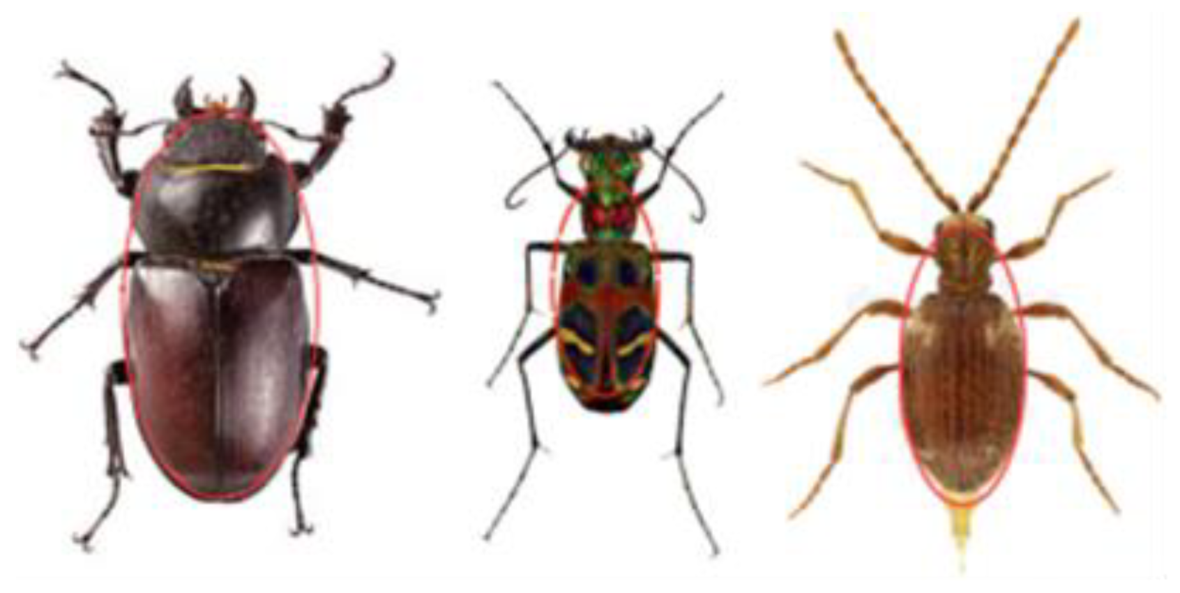
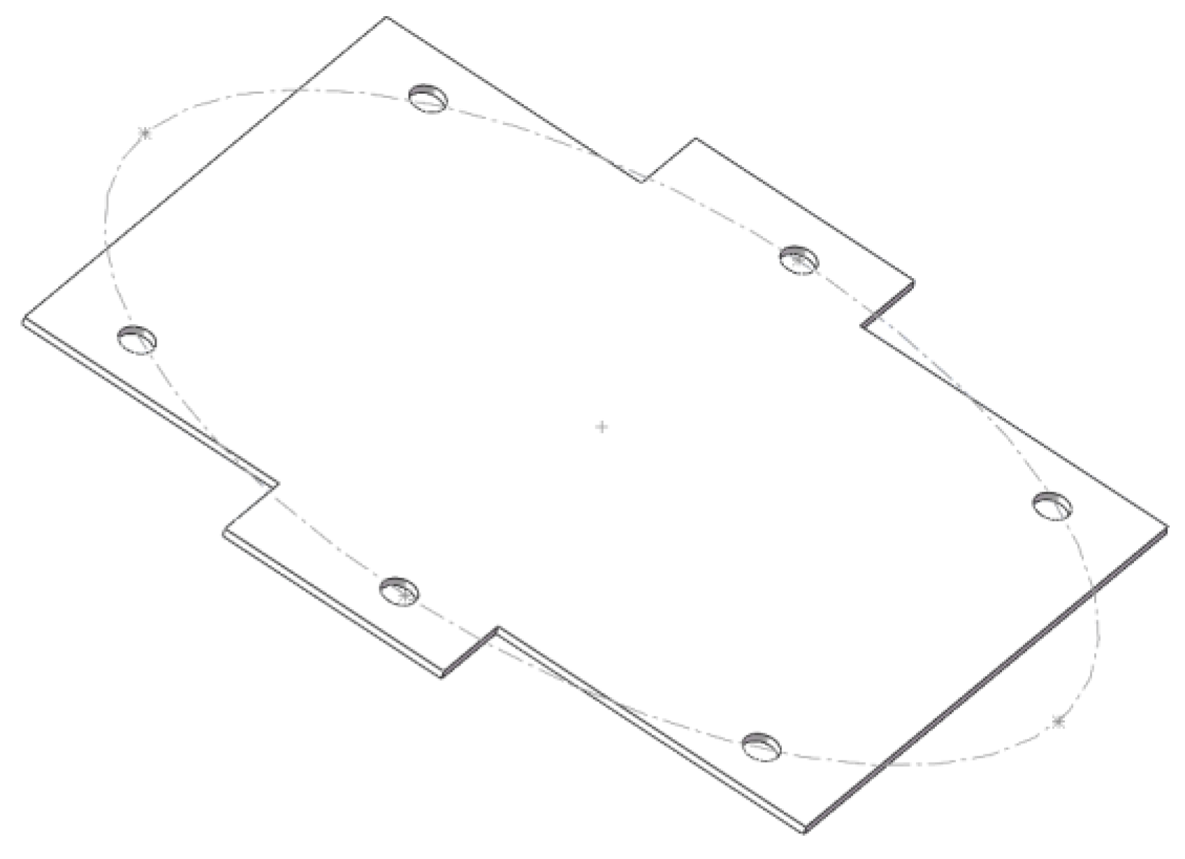
The lunar exploration robot should minimize its size and weight as much as possible, with an elliptical layout having a smaller volume compared to a circular layout. And, the elliptical layout not only ensures that the legs do not interfere with each other, but also has a large swing space. In addition, as shown in Figure 2, the leg distribution of hexapod insects in nature is often elliptical, so the final decision was made to adopt an elliptical layout. The final 3D model of the bottom plate design is shown in Figure 3.
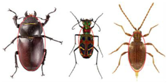
Figure 2.
Hexapod insect.
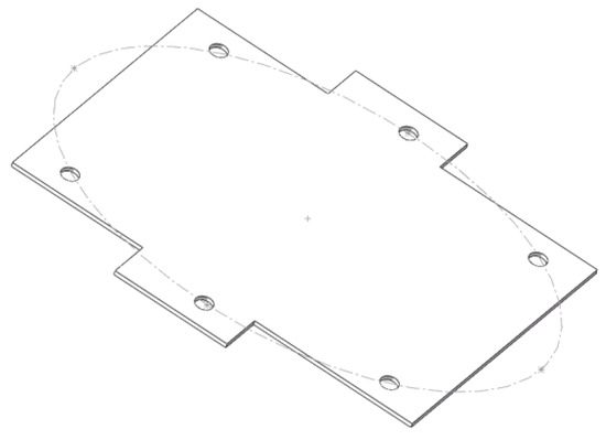
Figure 3.
A 3D modeling diagram of the fuselage.
2.2. Structural Design of the Legs of a Lunar Exploration Hexapod Robot
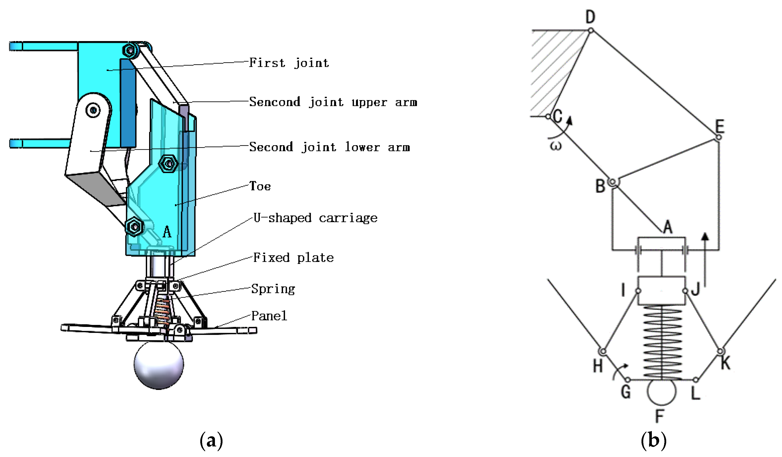
The leg structure of the robot needs to ensure that the robot can walk smoothly on lunar soil and has a good load-bearing capacity. Therefore, this paper designs a robot leg combining a four-bar linkage mechanism and an extension mechanism to achieve more stable and non-stuttering walking of the hexapod robot, as shown in Figure 4. The four-bar linkage mechanism consists of the first joint, the upper and lower arms of the second joint, and the foot tip. The first joint serves as the hip joint and is also the frame of the four-bar linkage mechanism. The second joint acts as the knee joint, with the lower arm connected to the steering engine as the active component, and both the upper and lower arms of the second joint act as connecting rods serving as rockers. The foot tip acts as the connecting rod, capable of performing the required lifting and lowering movements. Therefore, the four-bar linkage mechanism reduces the number of naked joints while achieving the trajectory of a three-joint single leg. An extension mechanism is added to the foot tip. When the robot walks on a rough surface, in the support phase, the rotation angle of the lower arm of the second joint increases, causing end A to contact the U-shaped slider. The U-shaped slider moves to the lowest point, driving four panels with flexible fabric to fully unfold, resulting in an umbrella-shaped foot tip. At this point, the contact area between the robot and the lunar soil increases, effectively dispersing the weight and ensuring walking stability. In the swing phase, the lower arm of the second joint rotates in the direction away from the ground, and the spring pushes the U-shaped slider upward, moving it to the highest point.
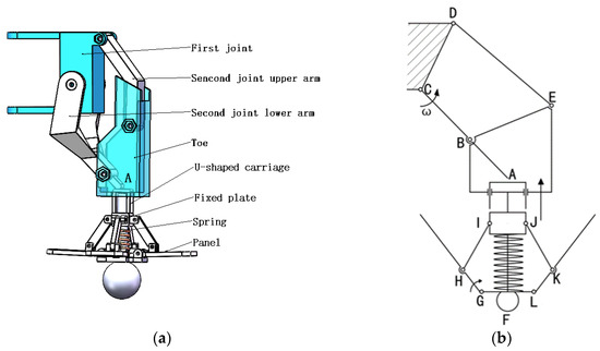
Figure 4.
Single Leg Structure Diagram: (a) single leg structure diagram; (b) single leg exercise diagram.
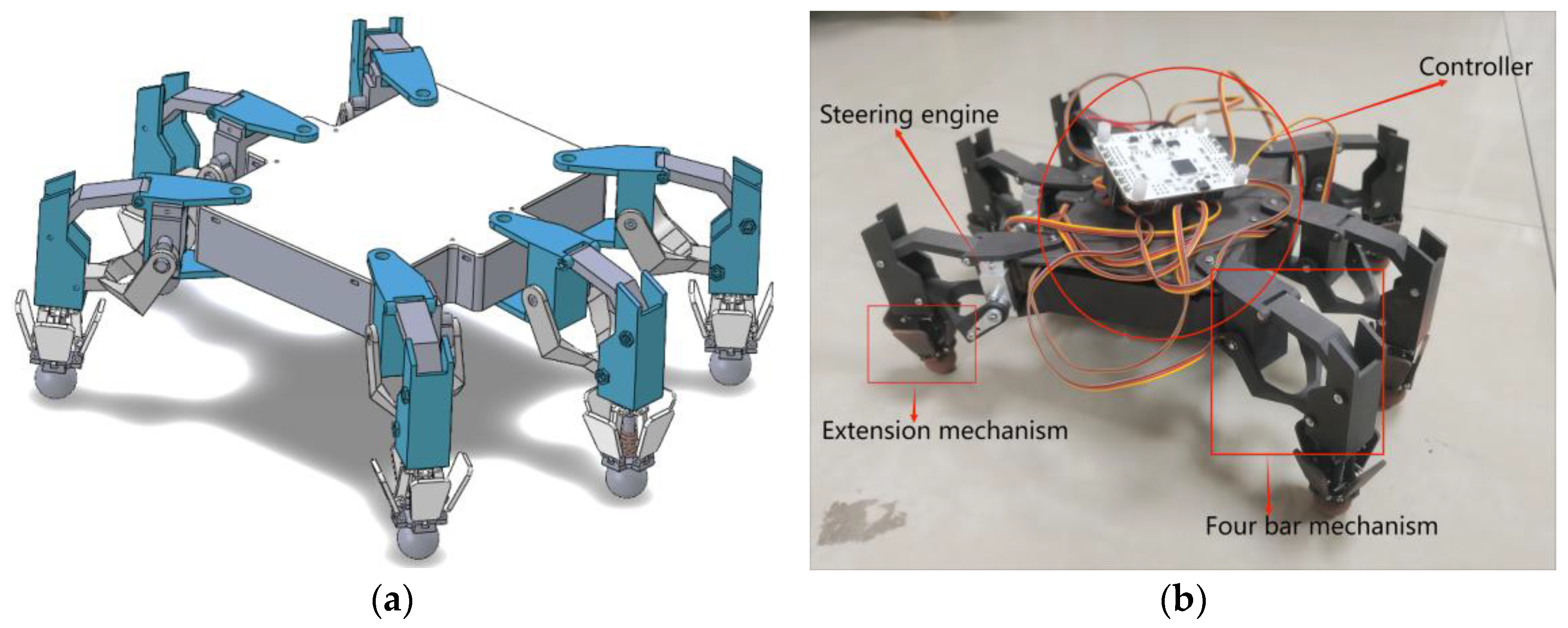
For the overall structure, the four-bar mechanism replaces the bare joint, and the steering gear serves as the power source for the lower arm of the second joint, driving the upper arm of the second joint to rotate and cleverly combining with the bottom extension mechanism. This allows a single leg to have two degrees of freedom, enabling the lifting and lowering of the leg, as well as a simpler control and lighter leg structure. The overall structure of the hexapod robot is shown in Figure 5.
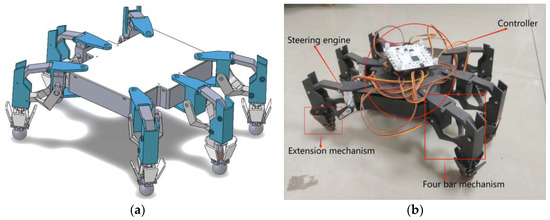
Figure 5.
Overall Structure Diagram: (a) model diagram; (b) prototype diagram.
3. Kinematic Analysis of the Lunar Exploration Hexapod Robot
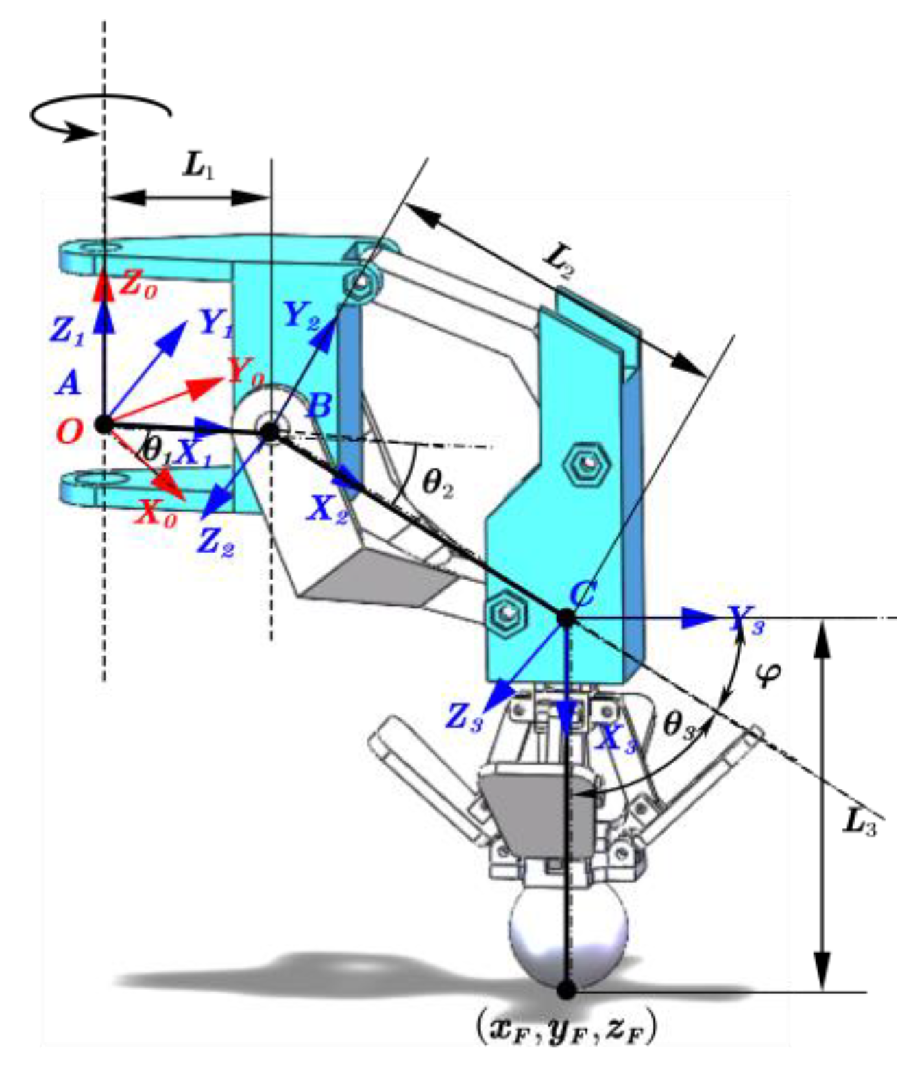
The motion of the lunar exploration hexapod robot is a process in which each leg changes over time, and the legs drive the robot to walk in various gaits through changes in joint angles [22]. Kinematic modeling can quantitatively analyze the impact of joint angle changes on foot motion, making it easier to study the overall mechanism and understand its motion characteristics. Due to the fact that the upper arm of the second joint in the four-bar linkage mechanism merely maintains the foot tip (extension mechanism) in a vertical downward position, its angular variation is irrelevant to the single-leg analysis and has no impact on other angular analyses. Therefore, it can be disregarded when establishing the D-H coordinate system. Coordinate systems for the three joint rotation centers are established according to the right-hand rule, as illustrated in Figure 6, where coordinate system O serves as the base coordinate system. The distances from the hip joint to the foot tip F are denoted as L1, L2, and L3, while θ1 and θ2 represent the rotation angles of the hip and knee joints, and θ3 represents the rotation angle of the lower arm of the second joint. The hip and knee joints are considered active degrees of freedom, and the rotation of the lower arm of the second joint is a coupled motion with the knee joint, serving as a passive degree of freedom. Since the foot tip remains vertically downward, θ2 = φ. In the Y3CX3 plane, φ + θ3 = π/2, hence θ2 + θ3 = π/2. Additionally, for a better analysis of the relationship between the foot tip F and θ1 and θ2, and also considering minimal practical rotational angle errors of the steering engine, coordinate system C is slightly offset to the right. The final single leg D-H coordinate system parameters are shown in Table 1.
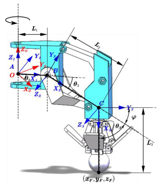
Figure 6.
Establishment of the D-H coordinate system for a single leg model.

Table 1.
Parameters in the D-H coordinate system.
The forward kinematics solution establishes a transformation matrix based on the base coordinate system by combining various parameters of the legs, and uses the transformation matrix to solve the position of the robot’s foot coordinate system relative to the base coordinate system O to obtain:
Matrix is the homogeneous transformation matrix from coordinate system i to coordinate system i − 1; the transformation matrix of the i coordinate system relative to the base coordinate system is:
The data brought into Table 1 shows:
The R is a 3 × 3 matrix of the three-footed pose is usually considered as a particle in the model, so it is not discussed. Note that, θ2 + θ3 = π/2. When the angles of each joint of the robot are known, the position of the foot endpoint F in the base coordinate system O can be obtained through a transformation formula as follows:
The analysis process of inverse kinematics of robots is opposite to forward kinematics, which involves calculating the rotation angles of each joint with known robot foot coordinates. From Equation (4), it can be concluded that
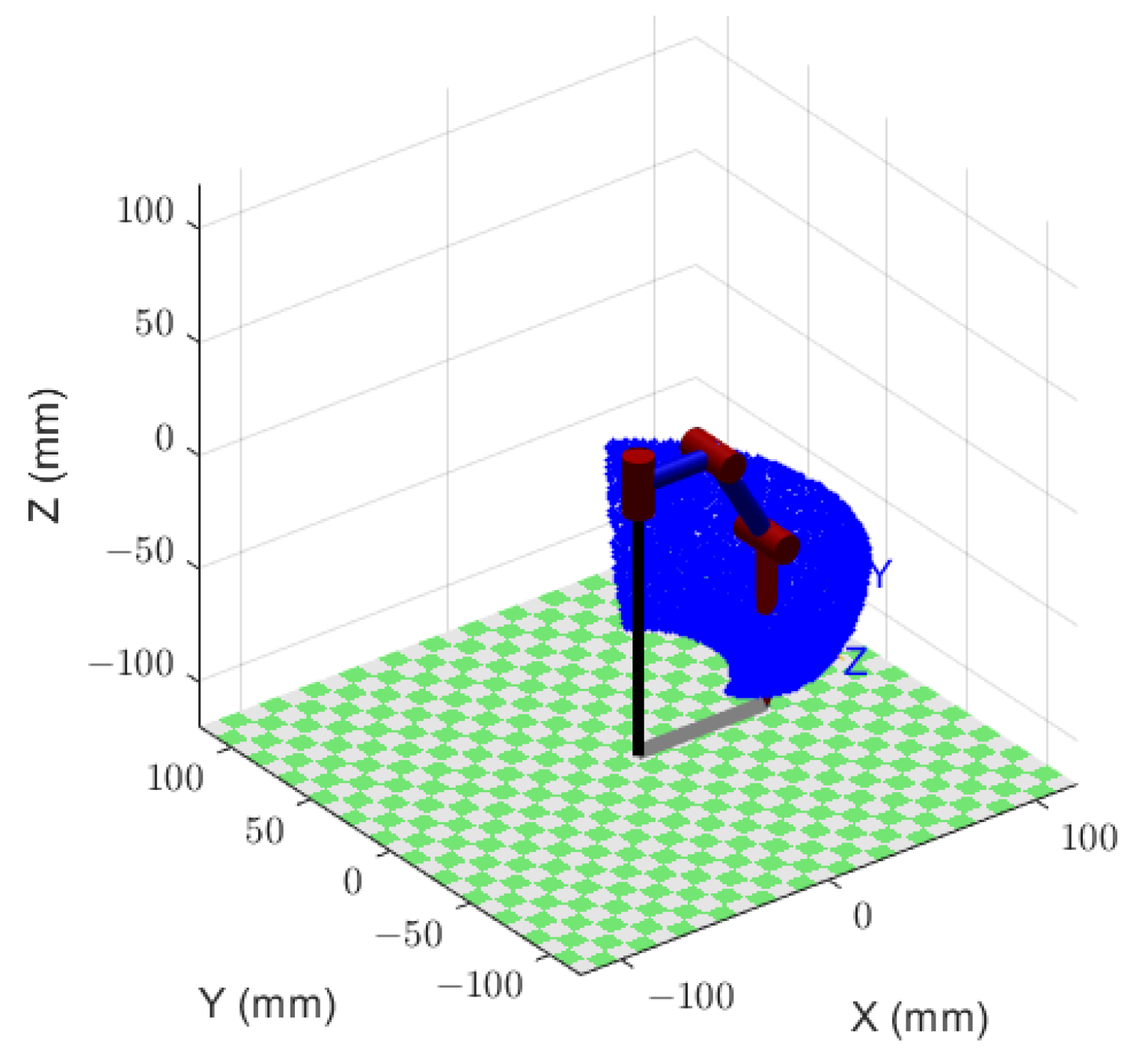
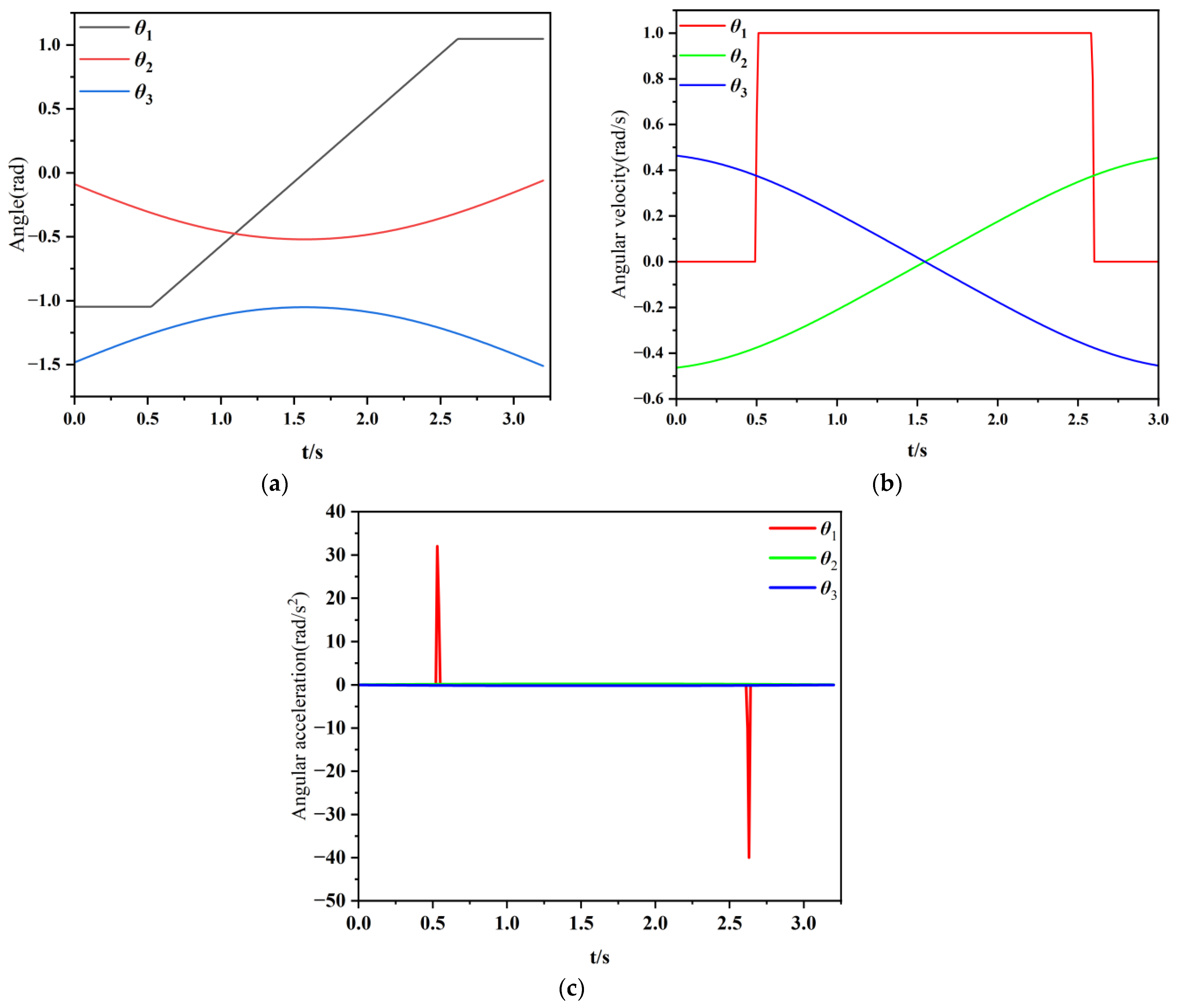
By utilizing various parameters in kinematics, the motion of a single leg can be analyzed to verify the rationality of the mechanism. Firstly, based on forward kinematics, the position of foot endpoint F at any time and the workspace that the foot can reach within the rotation range of each joint can be determined. Due to structural design limitations, the rotation angle of each joint will be constrained. Figure 7 shows the workspace range achieved after adding the joint rotation range. It can be seen that the up and down swinging motion space is relatively large, which can meet the deployment and closure requirements of the extension mechanism. And, inverse kinematics calculates the motion variables of each joint of the robot through the position of the foot end F. Figure 8 shows the motion variables of each joint obtained by using Matlab analysis [23] and using a parameterized expression to raise point F forward by 12 mm. From Figure 8, it can be seen that the angular velocity and angular acceleration curves of each joint are basically smooth when the F point is off the ground and touches the ground, except for some effects when changing the direction. The peak impact value is not significant and can be adjusted by the motor. Therefore, the entire motion process of the robot is stable, in accordance with the laws of kinematics. Therefore, after simulation verification, the design of the linkage mechanism, degree of freedom distribution, and joint activity angle of the robot’s legs are reasonable, meeting the subsequent needs of the robot to use the CPG model for gait walking. To meet the subsequent requirements of the robot, here refers to the synergistic design of the four-bar mechanism and extension mechanism. The aim is to enable the robot to achieve its structural objectives while accomplishing walking tasks and laying the foundation for potential diverse future needs. Specifically, the term “robot requirements” is preliminarily defined as the robot functioning as a viable platform with adequate stability and mobility during normal walking.
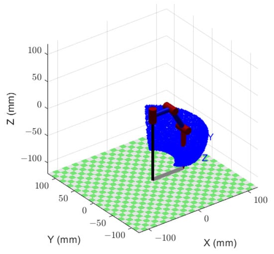
Figure 7.
Foot end workspace.
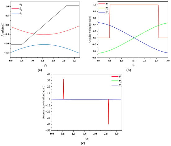
Figure 8.
Graph of motion variables of each joint: (a) rotation angle; (b) angular velocity; (c) angular acceleration.
4. Generation of CPG Tripod Gait Signal
4.1. Establishment of CPG Unit Model
The stable and fast motion of robots requires accurate control signals, and the Central Pattern Generator is a neural network that generates rhythmic motion and can output periodic oscillation signals as signals for each joint of the robot. Therefore, an oscillator model with few parameters, stable control, and easy implementation is required. Hopf oscillators belong to harmonic oscillators with fewer parameters and clear physical meanings. Each parameter individually affects the performance of the oscillator, and the amplitude, frequency, and phase of the output signal are easy to control [24]. The mathematical expression for a Hopf oscillator is
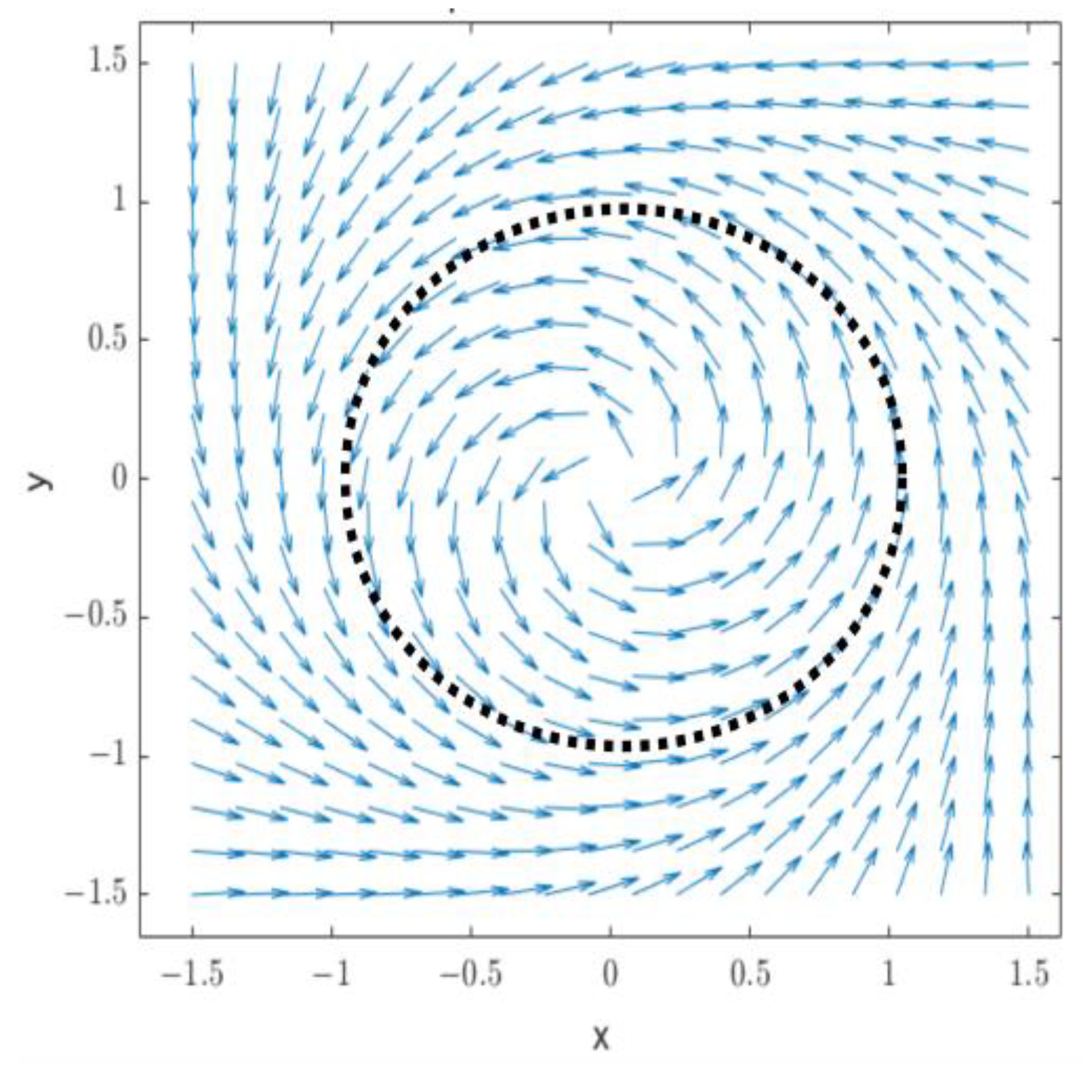
Among them, x and y are the state variables of the oscillator, which are the self-excited oscillation function of time t, that is, the output of the oscillator. α is the convergence rate coefficient used to control the convergence rate of the limit cycle, which is a normal number, and the larger the limit cycle, the faster it converges; μ is the square of the oscillator amplitude; and ω is the oscillation frequency of the oscillator. When there are no special circumstances, it is generally selected α = 100, μ = 1, ω = π. After running through Matlab, you can visually see the limit cycle of the Hopf oscillator, as shown in Figure 9.
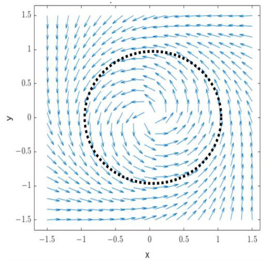
Figure 9.
Limit cycle of Hopf oscillator.
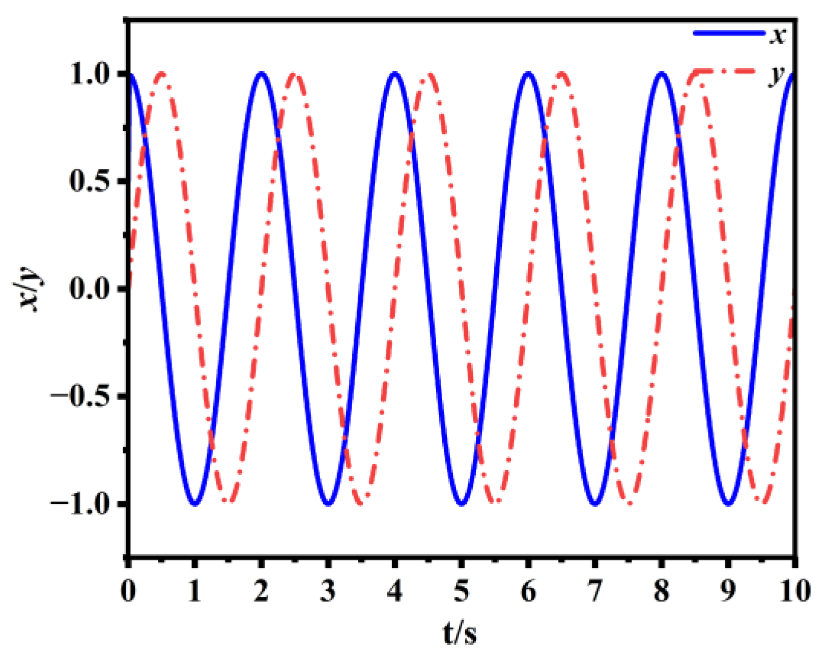
From Figure 9, it can be seen that regardless of the initial value, excluding unstable fixed points (0,0), the trajectory line in the Hopf oscillator model tends to a limit cycle with a radius of 1. This indicates that the Hopf oscillator has good stability at any initial output value. Figure 10 shows the oscillator output curve when x = 0.5 and y = 0.
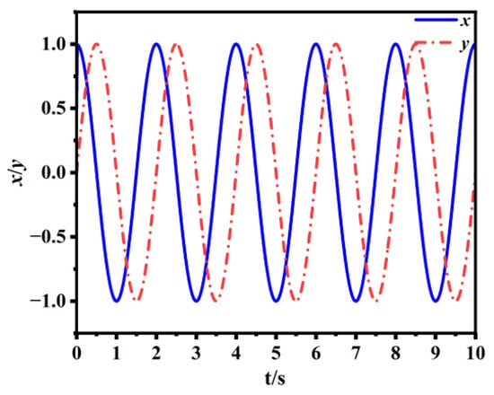
Figure 10.
Output curve of oscillator.
From Figure 10, it can be seen that Hopf can generate stable periodic oscillation signals. The rising segment of the output waveform represents the curve of the swinging leg of the robot during walking, while the falling segment represents the curve of the leg support phase during walking, and the rising and falling segments have the same time. In the gait, the movement of the hip and knee joints requires periodicity to ensure the naturalness and balance of the gait. Therefore, x and y can be used as output signals to control the hip and knee joints of the lunar exploration hexapod robot.
4.2. Generation of Single Leg Signals
Due to the use of a four-bar mechanism instead of the ankle joint and the addition of an extension mechanism, only the control signal of the knee joint [25] is required, and after simplifying the function the closure coefficient b1 and b2 are added, resulting in the following expression:
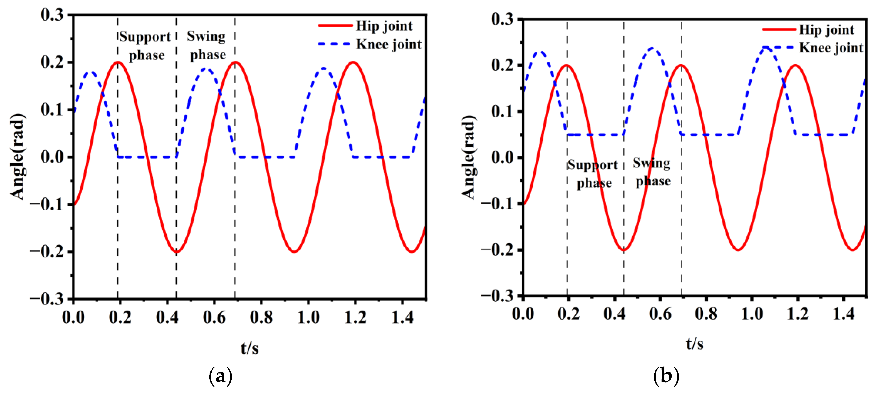
where: k0 is the mapping coefficient of the hip joint; k1 and k2 are the mapping coefficients of the knee joint; while b1 and b2 are the closure coefficients of the extension mechanism when controlling the mechanical leg to contact the ground. As shown in Figure 10, the signal of the y-curve will appear positive and negative. When the leg is in the support phase, the knee joint needs to remain stationary, so only the positive part is taken. Combined with the mechanical structure parameters of the lunar exploration hexapod robot in this article, k0 = 0.4, k1 = 0.3, and k2 = 0 are taken. When walking on the lunar pothole surface, if the extension mechanism of the robot is deployed when it lands, the walking will be more stable. At this time, b1 = 0, b2 = 0, and the signal is shown in Figure 11a. When walking on a flat section of the lunar surface, the deployment of the extension mechanism is no longer necessary, and the steering gear can have an initial angle of b1 = 0.05 and b2 = 0. As shown in Figure 11b, when the 0.19–0.41 s robot is in the support phase, the knee joint will have an initial angle, which will not push the U-shaped carriage. Therefore, the angle range of the knee joint can be adjusted by controlling the size of k1 and b1, thereby controlling the expansion and closure of the mechanical toe extension mechanism. The analysis of both cases is the same, and this article selects b1 = 0 and b2 = 0 for analysis.
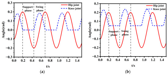
Figure 11.
Control signal diagram of single leg under different b1 and b2 conditions: (a) b1 = 0, b2 = 0; (b) b1 = 0.05, b2 = 0.
4.3. Three-Legged Gait Signal Generation
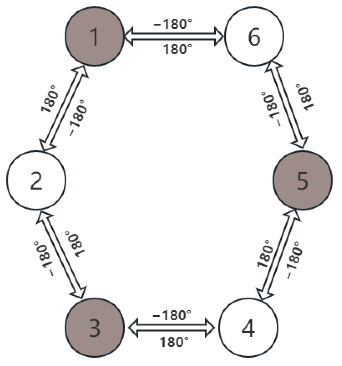
The single leg signal has already been generated in the previous section, and the oscillators of the robot’s single leg need to be coupled with each other to continuously output the signal in order for the lunar exploration hexapod robot to adopt a three-legged gait. This article adopts a ring coupled network topology as the signal output [26], and its mathematical model is
λ is the coupling strength parameter between the two oscillators, and this article takes λ = 0.6; xi and yi are state variables for each leg, θji is the phase difference between the oscillators i and j, i = j = 6, θji = θi − θj. In the tripod gait, the legs of the robot are divided into two groups: 1, 3, 5, and 2, 4, 6. The phase difference between the two groups is 180°, and the phase between the same group is consistent. The circular coupling network is shown in Figure 12. The overall modeling dimensions in Solid works include a longitudinal length of 200 mm and a width of 150 mm for the torso, a height of 148 mm from the ground when the extension mechanism is fully extended, and a height of 120 mm from the ground when the extension mechanism is closed.
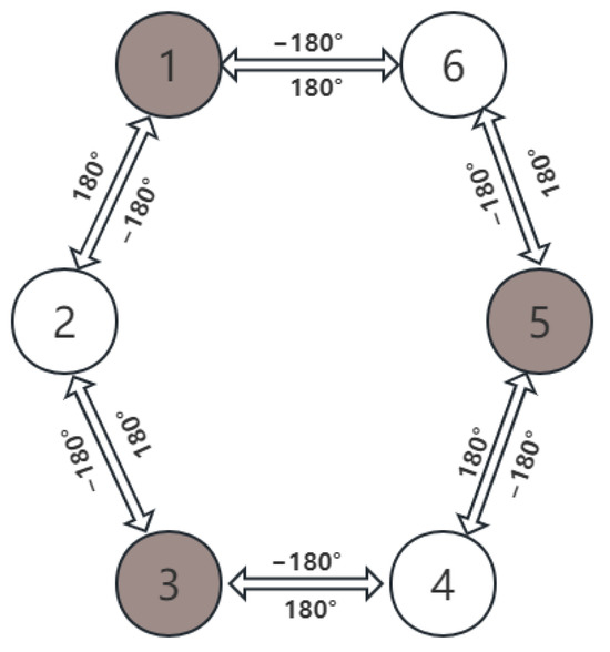
Figure 12.
Tripod gait CPG circular coupling diagram.
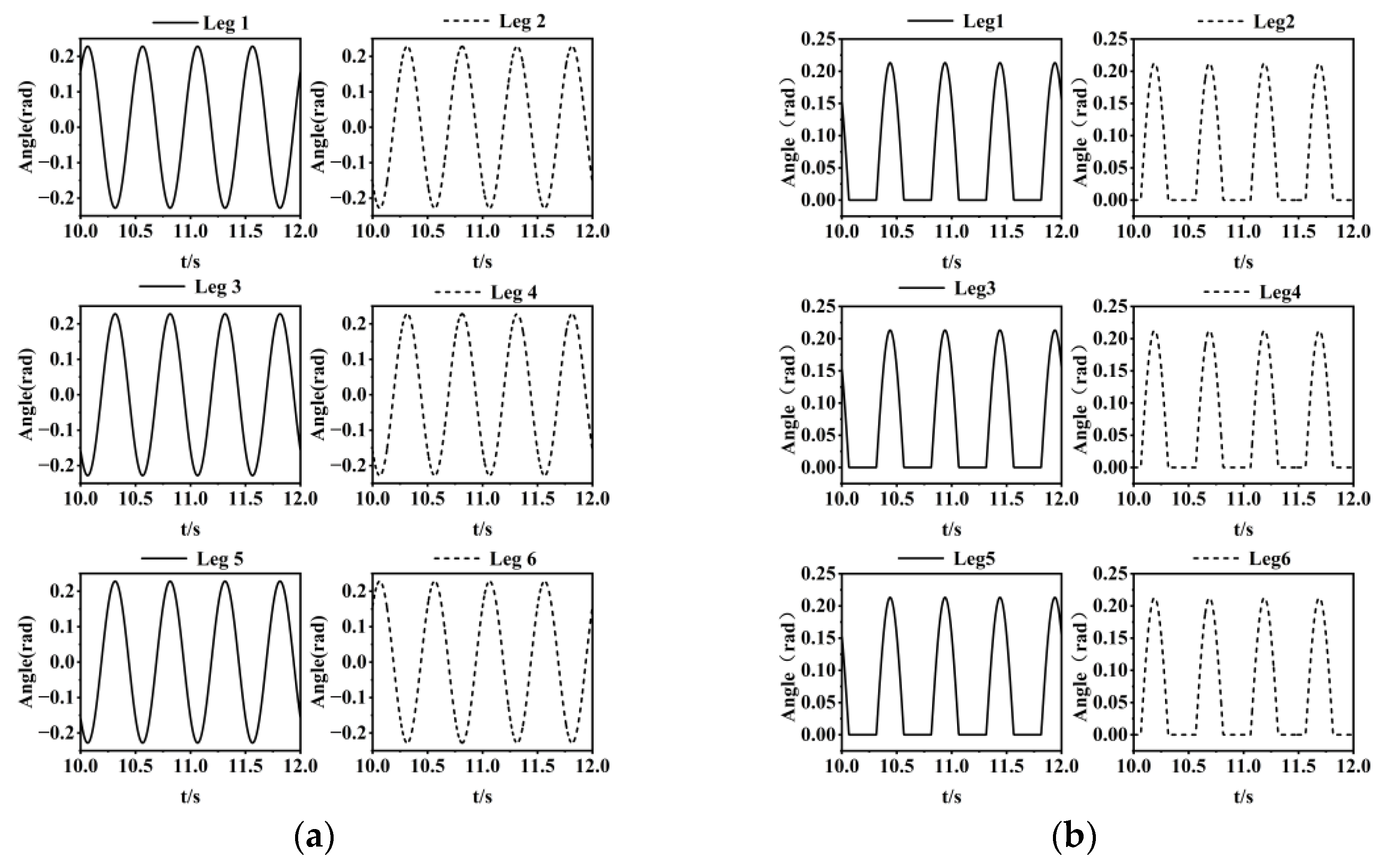
When utilizing Solid Works and Simulink/Simscape for simulation to verify the correctness of gait and substituting the parameters set earlier, the control signal for each leg of the robot when moving straight can be obtained as shown in Figure 13.
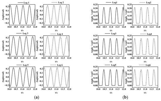
Figure 13.
Signal maps of different joints after coupling of each leg: (a) hip joint signal map; (b) knee joint signal map.
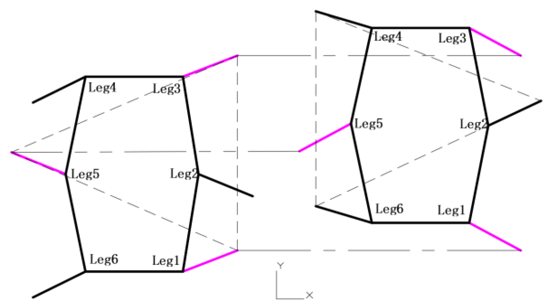
From Figure 14, it can be seen that when the robot is traveling straight, Legs 1, 3, and 5 are in the swinging phase from 10.1 s to 10.3 s, which is the rising phase of the hip joint signal. At this time, if the knee joint rotation angle is greater than 0, it is in the lifting posture, while Legs 2, 4, and 6 are in the supporting phase, which is the falling phase of the hip joint signal. If the knee joint rotation angle is 0, it is in the contact posture with the ground, and the support points of the three legs are triangular. From the schematic diagram 15 of the robot’s straight travel, it can be seen that during straight travel, Legs 1 and 3 swing in the same direction, while Leg 5 is opposite to both. This can be reflected in the fact that when Legs 1 and 3 rotate clockwise, Leg 5 rotates counterclockwise, forming periodic motion in conjunction with Legs 2, 4, and 6.
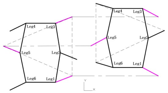
Figure 14.
Straight line diagram.
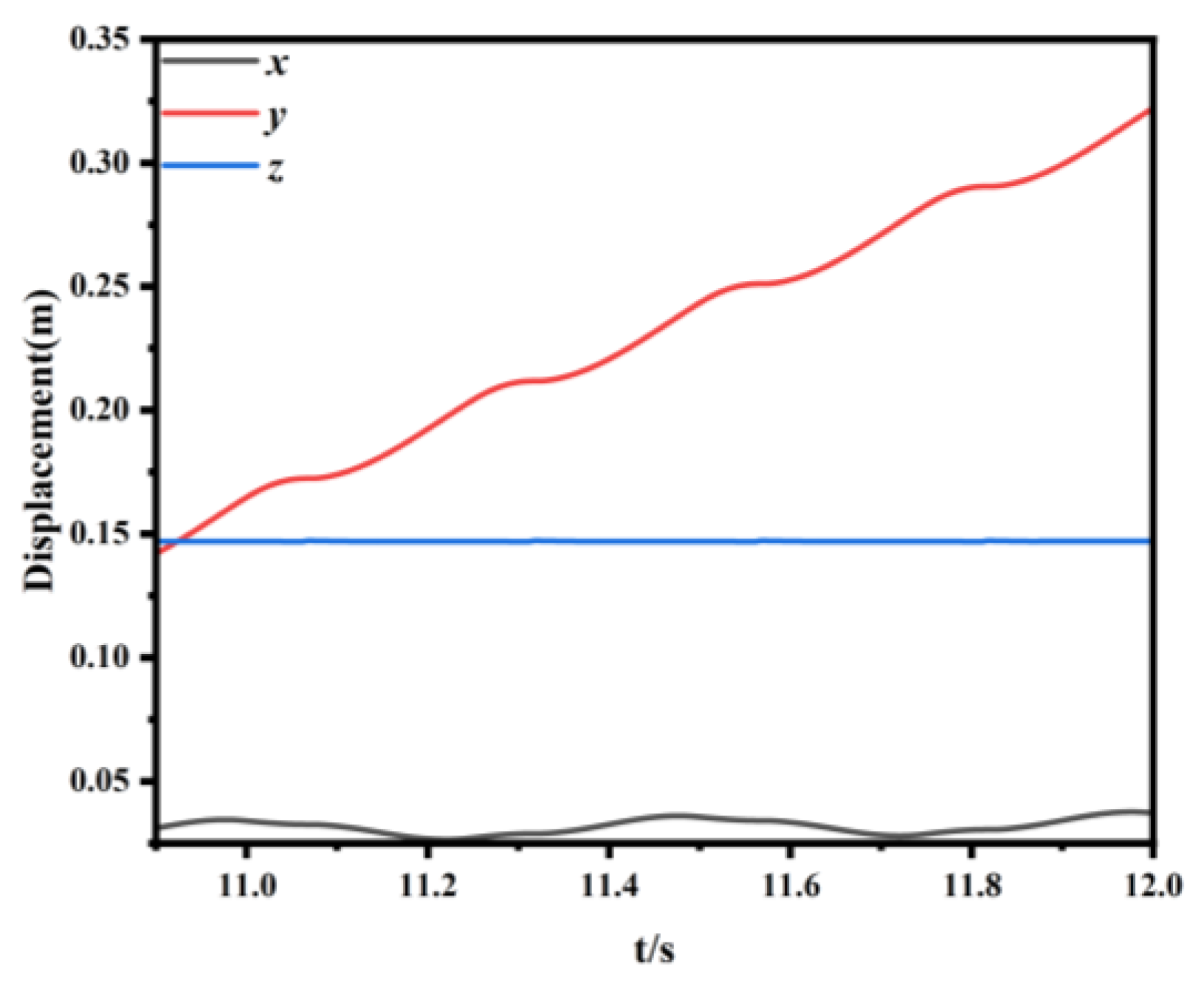
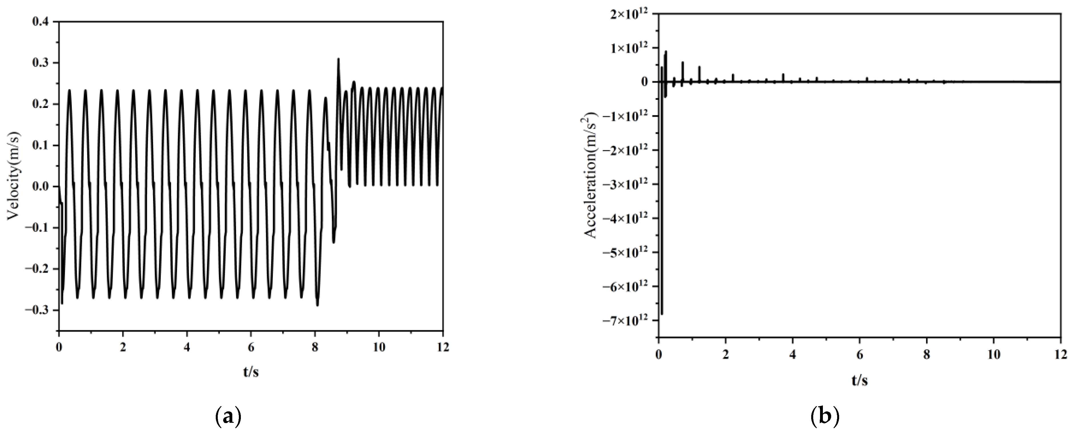
Figure 15 shows the displacement curves of the robot’s center of mass in the x, y, and z directions. The directions of y and x are consistent with Figure 14; y is the forward direction of the robot, x is the right offset direction of the robot, z is perpendicular to the ground and is in the opposite direction of the force of gravity on the robot. From Figure 15, it can be seen that the robot walked 0.32 m in 12 s when traveling straight, and its centroid had a maximum amplitude in z-direction of 2.1 × 10⁻⁴ m, and a maximum offset in x-direction of 3.1 × 10⁻³ m, with very small fluctuation amplitude and offset. From Figure 16, it can be seen that the speed of the robot experiences positive and negative fluctuations in the coupling of its six legs in the first 9 s. After 9 s, the speed is very smooth and the average speed is stable. The acceleration of the robot also increases instantly at the beginning, but the fluctuations are very small after 9 s. The simulation of the gait shows that the lunar exploration hexapod robot adopts a reasonable gait design. When walking straight ahead, the robot’s motion is very smooth and maintainable.
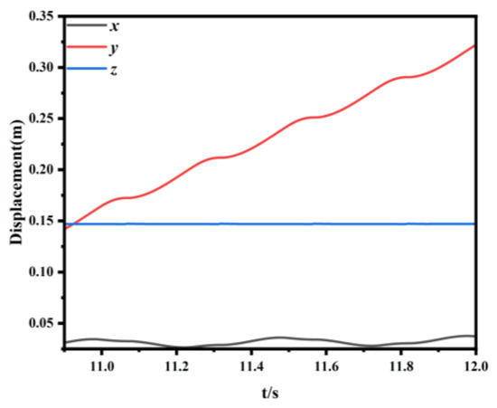
Figure 15.
The displacement curve of the robot’s center of mass in the x, y, and z directions during walking.
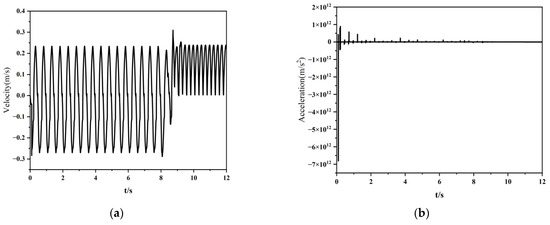
Figure 16.
The motion variable of the center of mass in the y direction during straight travel: (a) velocity profile; (b) acceleration variation diagram.
5. Prototype Experiment of a Lunar Exploration Hexapod Robot
The test site is located in the Lunar Test Module at Southeast University, where the simulated lunar soil is CAS-1 developed and produced by the Chinese Academy of Sciences. Walking experiments were conducted inside the test module with prototypes of both the lunar exploration hexapod robot and the traditional hexapod robot. The goal was to validate whether the lunar exploration hexapod robot prototype could walk smoothly on lunar soil under the three-legged gait signals generated by the CPG output, and to specifically demonstrate its advantages compared to traditional robots. The main parameters of the lunar exploration robot and the traditional robot are presented in Table 2.

Table 2.
Robot structural parameters.
5.1. Motion of Traditional Hexapod Robots
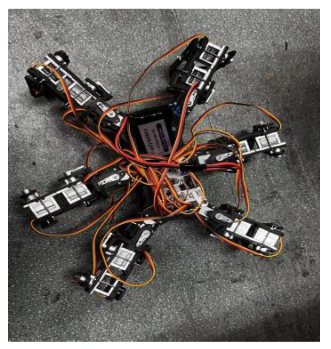
The physical illustration of the traditional hexapod robot is depicted in Figure 17, featuring a total of 18 degrees of freedom with three active degrees of freedom for each leg. The elliptical layout of the legs, construction materials, servos, and input signals for the traditional hexapod robot are consistent with those of the lunar exploration robot. The walking scenario is illustrated in Figure 18, where the leg landing points form a triangular support, and the movement of the two leg groups exhibits periodicity. According to actual measurements, the prototype walked approximately 150 mm in 12 s. However, the traditional robot encounters a situation of stationary stepping due to insufficient support force caused by the foot sinking into the lunar soil.
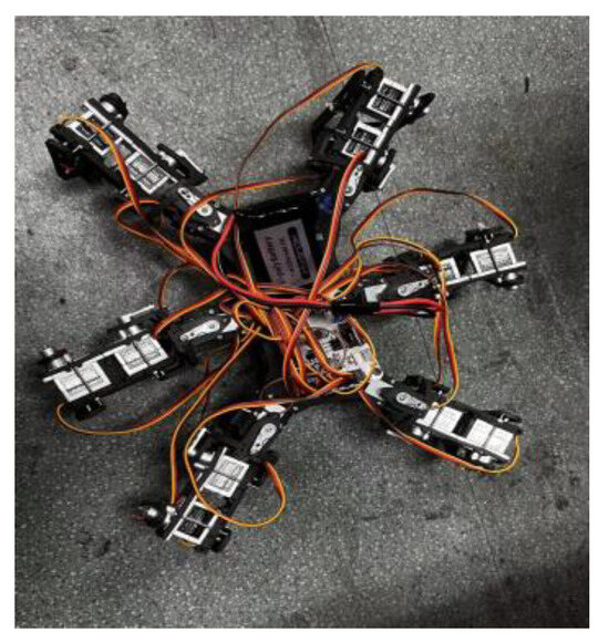
Figure 17.
Traditional hexapod robot.

Figure 18.
Walking situation diagram.
5.2. Movement of the Lunar Hexapod Robot
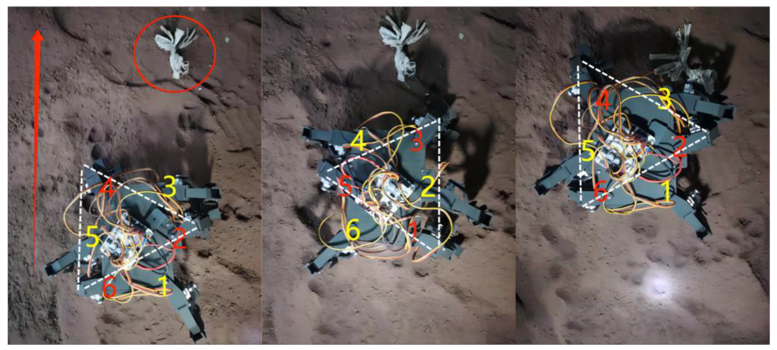
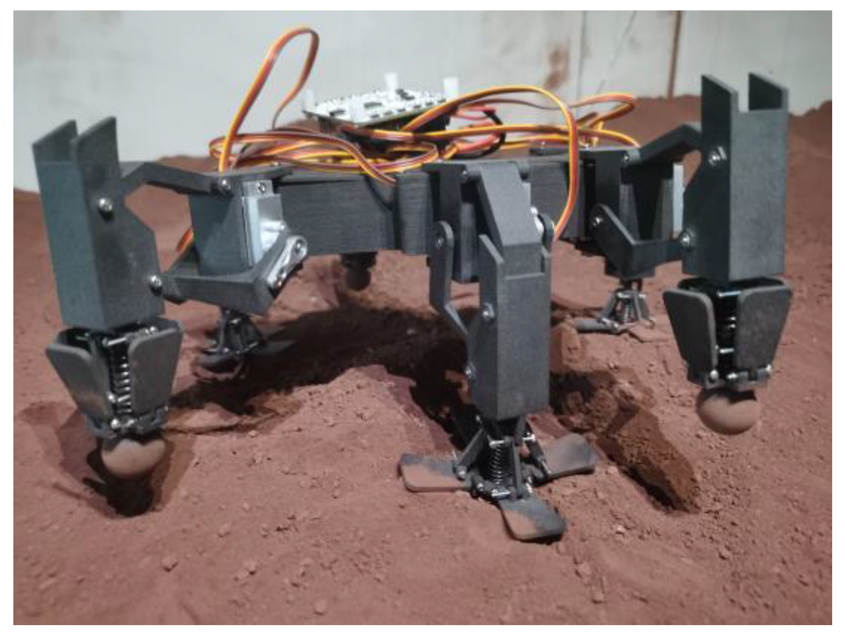
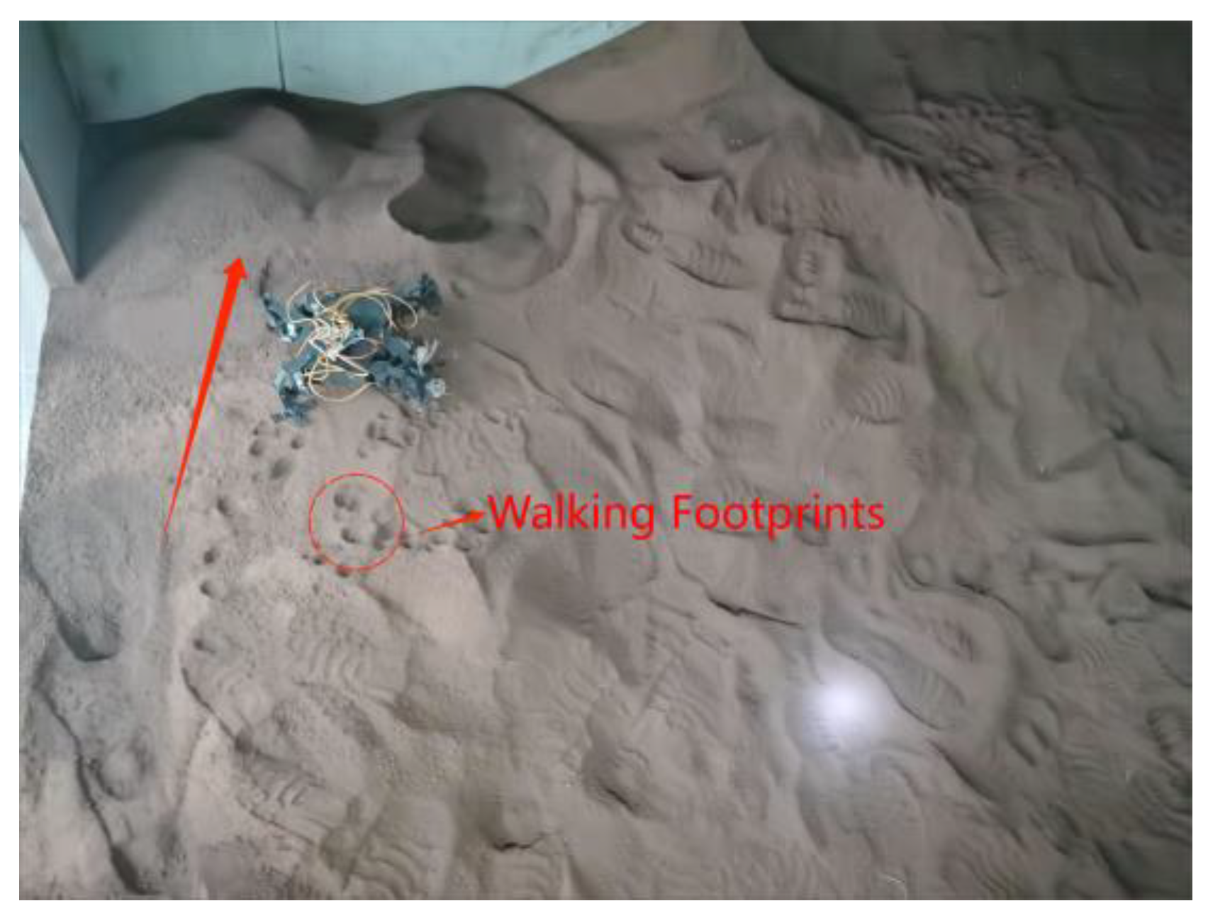
Figure 19 is a top view of the walking process of the prototype in a three-legged gait, with a white knot as the target. The legs are divided into two groups: 1, 3, 5, and 2, 4, and 6. The red numbers represent the legs when in the supporting phase, the yellow numbers represent the swinging phase, and the red arrows represent the direction of motion. From Figure 19, it can be seen that when Legs 1, 3, and 5 are lifted, the landing points of Legs 2, 4, and 6 are triangular in shape to provide stable support, and the movements of the two groups of legs are periodic. Figure 20 is a side view of the robot walking. It can be seen that the circular foot ends of the prototype are basically covered by lunar soil during walking. At this time, the extension mechanism is extended and supported on the lunar soil to prevent further foot sinking. This reduces the resistance of the foot during the next lift, making the walking of the prototype more stable, and avoiding overturning and deviation from the target point. Figure 21 shows the walking trajectory of the prototype. According to actual measurements, the prototype walked a distance of approximately 230 mm within 12 s. In the 230 mm straight walk, the prototype shifted to the left by approximately 32 mm. Compared with the simulation results, due to the soft and bumpy lunar soil of the lunar module, insufficient accuracy of the servo and installation errors, the robot’s footprint is not in a vertical line but a diagonal line, and still within the error range.
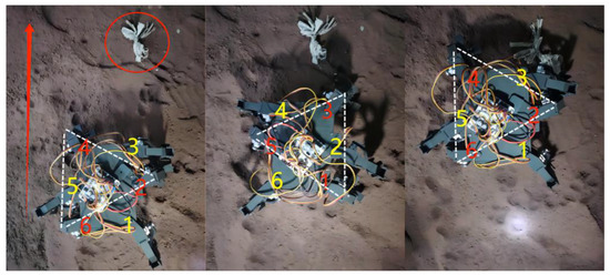
Figure 19.
Walking top view.
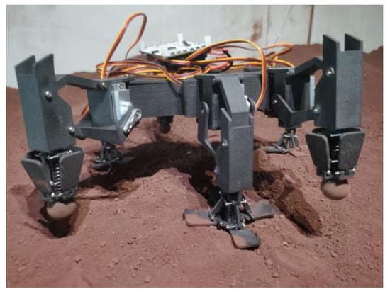
Figure 20.
Walking profile view.
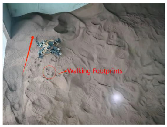
Figure 21.
Walking footprint map.
Comparative experimental results indicate that the lunar exploration hexapod robot designed in this study, during the experiment with the three-legged gait generated by the CPG model output, exhibits smoother motion compared to traditional hexapod robots. The lunar exploration robot can maintain a speed of 19.6 mm/s, demonstrating coordinated gait, reasonable structure, and the ability to meet pre-designed motion requirements. Moreover, it successfully avoids issues such as foot sinking leading to instability, tipping, or remaining stationary on the lunar surface (see Video S3).
6. Conclusions
Inspired by insects and incorporating characteristics of the traditional 18 degree of freedom hexapod robots, a lunar exploration hexapod robot with umbrella-shaped feet is developed. The robot, designed for the lunar environment, simplifies its structure through a four-bar linkage mechanism, reducing the number of joints and simplifying the control system. This reduction in complexity enhances the robot’s reliability and controllability, particularly in the soft lunar soil conditions. An extension mechanism is added to the foot, refining the mapping function control for precise closure during single-leg movement. When unfolded, the foot takes on an umbrella shape, providing a larger support area that evenly distributes the robot’s weight, minimizing pressure on the lunar soil and reducing the risk of sinking. This enhances the robot’s stability on the lunar surface. The entire robot is modeled in Solid Works, utilizing the Hopf oscillator model and precise control of the extension mechanism through mapping functions. Joint simulations are performed in Matlab, establishing a CPG control model for the robot, generating stable and smooth phase-locked signals for straight-walking simulation analysis using a tripod gait control. Finally, comparative experiments on the prototype’s walking are conducted, indicating that the lunar exploration hexapod robot has a rational structure, exhibits superior walking performance compared to traditional hexapod robots, and achieves the predefined motion requirements with smooth and stable motion. It can serve as a stable and smooth walking platform, equipped with sensors and other measuring equipment to meet the measurement requirements in various lunar environments.
Supplementary Materials
The following are available online at https://www.mdpi.com/article/10.3390/act13020079/s1, Video S1: single leg exercise video, Video S2: traditional robot walking video, Video S3: video of the lunar exploration hexapod robot walking.
Author Contributions
Conceptualization, Y.-Q.G. and B.-M.S.; methodology, Y.-Q.G.; software, B.-M.S. and W.-H.L.; validation, Y.-Q.G., Z.-D.X. and B.-M.S.; formal analysis, Y.-Q.G., W.-H.L. and B.-M.S.; investigation, B.-M.S. and Q.X.; resources, Y.-Q.G. and Z.-D.X.; data curation, B.-M.S., W.-H.L. and Q.X.; writing—original draft preparation, Y.-Q.G. and B.-M.S.; writing—review and editing, Y.-Q.G. and B.-M.S.; visualization, Y.-Q.G. and B.-M.S.; supervision, Y.-Q.G.; project administration, Y.-Q.G.; funding acquisition, Z.-D.X. All authors have read and agreed to the published version of the manuscript.
Funding
This research was funded by the National Natural Science Foundation of China (NSFC) Integrated Project, grant number U2037602.
Institutional Review Board Statement
Not applicable.
Informed Consent Statement
Not applicable.
Data Availability Statement
Data are contained within the article and supplementary materials.
Conflicts of Interest
The authors declare no conflicts of interest.
References
- Wedler, A.; Schuster, M.J.; Müller, M.G.; Vodermayer, B.; Meyer, L.; Giubilato, R.; Vayugundla, M.; Smisek, M.; Dömel, A.; Steidle, F.; et al. German Aerospace Center’s Advanced Robotic Technology for Future Lunar Scientific Missions. Phil. Trans. R. Soc. A. 2021, 379, 20190574. [Google Scholar] [CrossRef] [PubMed]
- Yang, L.; Li, Y.; Zhang, Y. Numerical Investigation of the Ground-Based Thermal Environment Experimental Approaches to Reveal the Ice-Sublimation Phenomenon inside Lunar Regolith. Acta Astronaut. 2023, 205, 295–309. [Google Scholar] [CrossRef]
- Belo, F.A.W.; Birk, A.; Brunskill, C.; Kirchner, F.; Lappas, V.; Remy, C.D.; Roccella, S.; Rossi, C.; Tikanmäki, A.; Visentin, G. The ESA Lunar Robotics Challenge: Simulating Operations at the Lunar South Pole. J. Field Robot 2012, 29, 601–626. [Google Scholar] [CrossRef]
- Bo, Z.; Feng, Y.; Huang, W.; Cui, Y. Diffusion Phenomenon of Lunar Soil Particles under a Plume in a Vacuum Environment by Numerical Simulation. Acta Astronaut. 2020, 171, 403–414. [Google Scholar] [CrossRef]
- Dunker, P.A.; Lewinger, W.A.; Hunt, A.J.; Quinn, R.D. A Biologically Inspired Robot for Lunar In-Situ Resource Utilization. In Proceedings of the 2009 IEEE/RSJ International Conference on Intelligent Robots and Systems, St. Louis, MO, USA, 10–15 October 2009; IEEE: St. Louis, MO, USA, 2009; pp. 5039–5044. [Google Scholar]
- Martinez Rocamora, B.; Kilic, C.; Tatsch, C.; Pereira, G.A.S.; Gross, J.N. Multi-Robot Cooperation for Lunar In-Situ Resource Utilization. Front. Robot. AI 2023, 10, 1149080. [Google Scholar] [CrossRef]
- Xiong, G.; Guo, X.; Yuan, S.; Xia, M.; Wang, Z. The Mechanical and Structural Properties of Lunar Regolith Simulant Based Geopolymer under Extreme Temperature Environment on the Moon through Experimental and Simulation Methods. Constr. Build. Mater. 2022, 325, 126679. [Google Scholar] [CrossRef]
- Nguyen, H.D.; Dung, V.T.; Sato, H.; Vo-Doan, T.T. Efficient Autonomous Navigation for Terrestrial Insect-Machine Hybrid Systems. Sens. Actuators B Chem. 2023, 376, 132988. [Google Scholar] [CrossRef]
- Jiang, S.; Song, W.; Zhou, Z.; Sun, S. Stability Analysis of the Food Delivery Robot with Suspension Damping Structure. Heliyon 2022, 8, e12127. [Google Scholar] [CrossRef]
- Nguyen, H.D.; Sato, H.; Vo-Doan, T.T. Burst Stimulation for Enhanced Locomotion Control of Terrestrial Cyborg Insects. In Proceedings of the 2023 IEEE International Conference on Robotics and Automation (ICRA), London, UK, 29 May–3 June 2023; IEEE: London, UK, 2023; pp. 1170–1176. [Google Scholar]
- Si, W.; Zhu, Z.; Wu, G.; Zhang, Y.; Chen, Y.; Sha, J. Encoding Manipulation of DNA-Nanoparticle Assembled Nanorobot Using Independently Charged Array Nanopores. Small Methods 2022, 6, 2200318. [Google Scholar] [CrossRef]
- Zhu, Y.; Chu, K.; Chen, X.; Wang, X.; Su, H. Research and Application of a Multi-Degree-of-Freedom Soft Actuator. Sens. Actuators A Phys. 2022, 338, 113492. [Google Scholar] [CrossRef]
- Manoonpong, P.; Patanè, L.; Xiong, X.; Brodoline, I.; Dupeyroux, J.; Viollet, S.; Arena, P.; Serres, J.R. Insect-Inspired Robots: Bridging Biological and Artificial Systems. Sensors 2021, 21, 7609. [Google Scholar] [CrossRef]
- Chen, J.; Xie, F.; Huang, L.; Yang, J.; Liu, X.; Shi, J. A Robot Pose Estimation Optimized Visual SLAM Algorithm Based on CO-HDC Instance Segmentation Network for Dynamic Scenes. Remote Sens. 2022, 14, 2114. [Google Scholar] [CrossRef]
- Larsen, A.D.; Büscher, T.H.; Chuthong, T.; Pairam, T.; Bethge, H.; Gorb, S.N.; Manoonpong, P. Self-Organized Stick Insect-Like Locomotion under Decentralized Adaptive Neural Control: From Biological Investigation to Robot Simulation. Adv. Theory Simul. 2023, 6, 2300228. [Google Scholar] [CrossRef]
- Büschges, A.; Akay, T.; Gabriel, J.P.; Schmidt, J. Organizing Network Action for Locomotion: Insights from Studying Insect Walking. Brain Res. Rev. 2008, 57, 162–171. [Google Scholar] [CrossRef]
- Cao, F.; Sato, H. Remote Radio Controlled Insect-Computer Hybrid Legged Robot. In Proceedings of the 2017 19th International Conference on Solid-State Sensors, Actuators and Microsystems (TRANSDUCERS), Kaohsiung, Taiwan, 18–22 June 2017; IEEE: Kaohsiung, Taiwan, 2017; pp. 59–62. [Google Scholar]
- Niemeier, M.; Jeschke, M.; Dürr, V. Effect of Thoracic Connective Lesion on Inter-Leg Coordination in Freely Walking Stick Insects. Front. Bioeng. Biotechnol. 2021, 9, 628998. [Google Scholar] [CrossRef] [PubMed]
- van der Meer, D.; Chovet, L.; Bera, A.; Richard, A.; Sánchez Cuevas, P.J.; Sánchez-Ibáñez, J.R.; Olivares-Mendez, M. REALMS: Resilient Exploration and Lunar Mapping System. Front. Robot. AI 2023, 10, 1127496. [Google Scholar] [CrossRef] [PubMed]
- Tran-Ngoc, P.T.; Le, D.L.; Chong, B.S.; Nguyen, H.D.; Dung, V.T.; Cao, F.; Li, Y.; Kai, K.; Gan, J.H.; Vo-Doan, T.T.; et al. Intelligent Insect–Computer Hybrid Robot: Installing Innate Obstacle Negotiation and Onboard Human Detection onto Cyborg Insect. Adv. Intell. Syst. 2023, 5, 2200319. [Google Scholar] [CrossRef]
- Lordos, G.; Brown, M.J.; Latyshev, K.; Liao, A.; Shah, S.; Meza, C.; Bensche, B.; Cao, C.; Chen, Y.; Miller, A.S.; et al. WORMS: Field-Reconfigurable Robots for Extreme Lunar Terrain. In Proceedings of the 2023 IEEE Aerospace Conference, Big Sky, MT, USA, 4–11 March 2023; IEEE: Big Sky, MT, USA, 2023; pp. 1–21. [Google Scholar]
- Sun, C.; Yang, G.; Yao, S.; Liu, Q.; Wang, J.; Xiao, X. RHex-T3: A Transformable Hexapod Robot with Ladder Climbing Function. IEEE/ASME Trans. Mechatron. 2023, 28, 1939–1947. [Google Scholar] [CrossRef]
- Wang, J.; Chen, B.; Chen, W.; Song, R. The Design and Analysis of Cockroach Robot Based on the Couple Four-Bar Linkage Mechanism. In Proceedings of the 2010 5th IEEE Conference on Industrial Electronics and Applications, Taichung, Taiwan, 15–17 June 2010; IEEE: Taichung, Taiwan, 2010; pp. 109–114. [Google Scholar]
- Pinto, C.M.A.; Rocha, D.; Santos, C.P.; Matos, V. A New CPG Model for the Generation of Modular Trajectories for Hexapod Robots. AIP Conf. Proc. 2011, 1389, 504–508. [Google Scholar] [CrossRef]
- Li, M.; Wang, Z.; Zhang, D.; Jiao, X.; Wang, J.; Zhang, M. Accurate Perception and Representation of Rough Terrain for a Hexapod Robot by Analysing Foot Locomotion. Measurement 2022, 193, 110904. [Google Scholar] [CrossRef]
- Zhang, W.; Gong, Q.; Yang, H.; Tang, Y. CPG Modulates the Omnidirectional Motion of a Hexapod Robot in Unstructured Terrain. J. Bionic. Eng. 2023, 20, 558–567. [Google Scholar] [CrossRef]
Disclaimer/Publisher’s Note: The statements, opinions and data contained in all publications are solely those of the individual author(s) and contributor(s) and not of MDPI and/or the editor(s). MDPI and/or the editor(s) disclaim responsibility for any injury to people or property resulting from any ideas, methods, instructions or products referred to in the content. |
© 2024 by the authors. Licensee MDPI, Basel, Switzerland. This article is an open access article distributed under the terms and conditions of the Creative Commons Attribution (CC BY) license (https://creativecommons.org/licenses/by/4.0/).

