Abstract
Aimed at the stability problem of quadrotor Unmanned Aerial Vehicle (UAV) flight attitudes under random airflow disturbance conditions, a robust H-infinity-based dual cascade Model Predictive Control (MPC) attitude control method is proposed. Model Predictive Control itself has the capability to minimize the deviation between the prediction error and the control target by optimizing the control algorithm. The robust H-infinity controller can maintain stability in the face of system model uncertainty and external disturbances. The controller designed in this paper divides the attitude control loop into the following two parts: the angle loop and the angular velocity loop. The angle loop, serving as the main control loop of the attitude control, employs the robust H-infinity controller to process the angle of the quadrotor UAV and then transmits the processed value to the MPC controller. This approach reduces the computational load of the MPC controller. Simultaneously, by optimizing the algorithm, MPC minimizes the prediction error and the deviation from the control target. Simulation experiments confirm that the proposed algorithm improves the stability of the UAV attitude under random airflow disturbance conditions, while also achieving accurate tracking of the UAV’s position.
1. Introduction
With the rapid advancement of UAV technology, quadrotor UAVs have found extensive applications in the military, agriculture, logistics, and other sectors. However, during flight, these UAVs often face various uncertain environmental factors, with random airflow interference being one of the most common and challenging issues [1]. Analyzing the attitude control of UAVs under the influence of random airflow is crucial for enhancing their stability and maneuverability in complex environments. By improving control algorithms, UAVs can respond quickly, make the necessary adjustments to maintain stable flight, and ensure operational safety. Therefore, studying the control strategies for quadrotor UAVs under random airflow interference is of significant theoretical importance and practical value.
To ensure the stable flight of quadrotor UAVs under random airflow interference, researchers such as Javaid, S., Aláez, D., and Chen, M., among others [2,3,4,5,6,7], have explored various control algorithms, including UAV attitude control methods based on adaptive neural networks [5,6] and dual-gain proportional–derivative control algorithms. Traditional control methods often fall short when UAVs are affected by turbulent winds, due to the inherent nonlinear, multiple-input–multiple-output (MIMO), and parameter coupling characteristics of UAVs [8].
To address the impact of wind on UAV control, the commonly employed methods include PID control [9,10], sliding mode control [11,12], and backstepping [13,14]. However, Pang, Y. et al. [15] designed a nonlinear generalized minimum variance optimization controller with increasing dimensions, and Madebo, M. M. et al. [16] proposed a method to compensate for the uncertainties caused by perturbations through the use of neural networks. While these researchers have introduced significant advancements in UAV control algorithms, their controllers often struggle with tracking inaccuracies when turbulence is excessive or highly complex [17].
Bannwarth, J. X. et al. [18] employed a robust H-infinity dynamic output feedback controller for position regulation of a fully driven, rotating eight-rotor UAV, effectively suppressing perturbations caused by wind disturbances during positioning. Wang, Q. et al. [19] designed a novel perturbation-resistant sliding mode control, enabling the UAV to track trajectories accurately, robustly, and without shuddering under wind shear. Zhang, Q. et al. [20] proposed an observer-based switching control method, where the UAV selects the appropriate controller by switching between traditional Proportional–Integral–Derivative (PID) and Active Disturbance Rejection Control (ADRC), or Finite-Time Extended Disturbance Observer (FTEDO) in response to complex and variable ocean winds. Muthusamy, P. K. et al. [21] introduced a self-organizing bi-directional fuzzy brain affective learning controller, but it was found to be too slow to adapt with low learning efficiency. Cai, Z. et al. [22] developed an integrated control system with position feedback and attitude feedback control based on self-immobilizing control. Chen, C. et al. [23] proposed separate control strategies for the position and attitude loops, using Model Predictive Control (MPC) for the position loop and sliding mode control for the attitude loop, with both controllers integrated with nonlinear state observers to mitigate disturbances. Finally, Li, B. et al. [24] suggested a control strategy combining an extended state observer and a nonlinear disturbance observer to counteract system uncertainties and external wind disturbances.
Xu, Z. Q. et al. [25] designed an altitude and airspeed controller using a finite-time filter combined with the backstepping control method. This approach enabled the UAV to maintain smooth flight under wind disturbances while addressing the issue of “breeze explosion”, which is a common drawback of backstepping, by utilizing a command filter to obtain the derivative of the virtual control input. Liu, X. B. et al. [26] considered the lateral forces acting on the UAV fuselage during flight, which can cause it to slip sideways. To counter wind effects, they introduced the integral of trajectory deviation as feedback in the outer loop. However, this method is prone to integral windup when wind speeds are too high or change frequently. Zhao, H. C. et al. [27] aimed to improve the real-time performance and low-power efficiency of quadrotor UAVs by using a sliding mode controller based on an extended state observer. Their approach employed three state observers for state and position estimation to compensate for the total perturbations caused by uncertainties and external disturbances, while reducing the sliding mode variable structure’s increasingly high function gain to enhance robustness. Similarly, Zhang, J. Y. et al. [28] incorporated sliding mode control with strong disturbance resistance into the backstepping method to improve system robustness. They added an integral term to reduce steady-state error and employed an Extended State Observer (ESO) to predict and compensate for total system disturbances.
To address the uncertainties caused by varying loads, wind disturbances, spiral drag, and modeling inaccuracies in quadrotor UAVs, Sun, M. Y. et al. [29] proposed an MPC–DO–ESO controller approach. In this method, the Disturbance Observer (DO) and Extended State Observer (ESO) are used in the feed-forward part of the controller. The DO suppresses disturbances modeled as exogenous systems, and the combination of DO and ESO enhances the system’s anti-disturbance capability. Xue, J. Y. et al. [30] implemented an inner–outer loop control strategy. The inner loop controls the rotating subsystem to maintain flight attitude using an exponential time-varying gain convergence law, ensuring that the gain coefficients adjust exponentially with the system’s state. This addresses the issues related to the high convergence rate factors affecting the sliding mode surface. The outer loop controls the translational subsystem using backstepping quasi-slip-film control, reducing the jitter effects in the absence of position loop interference.
In conclusion, this paper proposes a dual cascade MPC approach based on robust H-infinity control. The position loop utilizes a traditional MPC controller, while the attitude loop employs dual cascade MPC control based on robust control to manage both the angle loop and the angular velocity loop. The angle loop serves as the primary control loop, focusing on maintaining UAV attitude, with robust H-infinity control processing the angular data of the quadcopter. These processed values are then sent to the MPC controller, reducing its computational burden. Algorithm optimization in the MPC minimizes the prediction error and the control target deviation. These improvements enhance the stability and accuracy of attitude and position tracking of the quadrotor UAV under random airflow disturbances.
In light of the proposed algorithm, this paper is organized into five sections. The first section establishes the random airflow model, treating random airflow as a perturbation variable. The second section develops the mathematical model of the quadrotor UAV to facilitate the smooth execution of subsequent simulation experiments. The third section focuses on enhancing the algorithm by employing dual cascade MPC attitude control based on robust H-infinity control, improving the quadrotor’s stability under random airflow interference. The fourth section verifies the feasibility of the algorithm through simulations, and the final section compares the proposed algorithm with traditional control methods, demonstrating its superior control performance.
2. Stochastic Air Flow Modeling
UAVs operating in outdoor wind fields are subjected to both low- and high-frequency airflow disturbances. The high-frequency component, characterized by random fluctuations, poses significant challenges to maintaining UAV flight stability. The Dryden and Von Karman turbulence models, both stochastic in nature, offer realistic representations of the power spectral density (PSD) of atmospheric turbulence across a wide range of frequencies. Notably, the Von Karman model provides broader spectral coverage, especially in the lower-frequency bands, making it more effective in simulating the vortex structures of atmospheric turbulence on larger scales.
Among these models, the Von Karman turbulence model generates turbulence by passing Gaussian white noise through a shaping filter. When the model’s frequency parameter ω approaches infinity, the generated stochastic flow closely approximates actual atmospheric turbulence. However, the model’s dependence on white noise complicates the Cholesky decomposition, presenting challenges in numerical simulation. As a result, this paper adopts the Dryden model for its simpler implementation.
To simulate turbulent wind fields using the Dryden model, the first step involves decomposing the model’s spectrum. This process transforms white noise into an atmospheric turbulence signal by constructing an appropriate filter.
where a = 1.34, represents the turbulence intensity in the x, y, and z directions, and denotes the turbulence scale in these respective directions, with V being the UAV flight speed.
From the literature [18,19], the spatial spectral expression of the Dryden model is given as follows.
where represents the spatial frequency, in accordance with the transformation between spatial and temporal frequencies, as given by the following equation:
The expression for the time spectrum of the Dryden model is obtained as follows:
where V is the flight speed of the quadrotor UAV, and ω represents the time frequency. Since Equations (1)–(4) are straightforward to square, and the corresponding filter is constructed accordingly. Numerical simulations are then conducted to generate the turbulent wind field based on the Dryden model. The initial simulations are performed under low-altitude conditions, with the following equations:
The wind speed at a height of 16.096 m is denoted as V, with h representing the height. To generate a turbulent wind sequence, the principle is applied in which an input signal r(t) passes through a filter G(s), producing the corresponding spectral model as follows:
Let the input signal be unit white noise, then simplifies Equations (2)–(7) to the following:
Therefore, the Dryden turbulence time spectrum expression (1)–(4) is decomposed according to the structure of (1)–(8), resulting in the following form:
Based on the derivation of the Dryden turbulence model and assuming a wind speed of 16 m/s at a height of 16.096 m, we account for the fact that UAVs are often used in canyon and sea environments, where wind speeds generally originate from various directions. By superimposing the wind fields in the x, y, and z directions, we create a variable random wind field that can occur in any direction. This method effectively simulates the external turbulent disturbances encountered in these environments.
3. Modeling of Unmanned Aircraft Systems
The structure of quadrotor UAVs can be categorized into the following two types: cross-shaped (QUAD +) and X-shaped (QUAD X). This paper utilizes the X-shaped configuration for platform construction, as illustrated in Figure 1. For better clarity, Figure 1 shows the motors in the following order from left to right and top to bottom: Motor 1, Motor 2, Motor 3, and Motor 4.
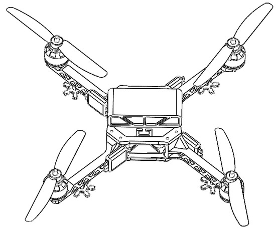
Figure 1.
Quadcopter UAV SolidWords Structure Diagram.
The quadrotor UAV’s power is generated by its four propellers. By varying the rotational speeds of these rotors, the UAV can alter its motion states, including forward, backward, roll, yaw, and pitch, as detailed in Table 1. During vertical motion, the UAV applies the same throttle value to all four motors (1, 2, 3, and 4). For pitch motion, Motors 1 and 2 increase their speeds, while Motors 3 and 4 decrease theirs. In Table 1, a “-” denotes deceleration, and a “+” denotes acceleration.

Table 1.
Motion control schematic for the QUAD X layout of a quadcopter UAV.
The mechanical structure of the quadrotor UAV is shown in Figure 1.
To achieve equilibrium control of the UAVs under random airflow disturbance conditions, it is first necessary to establish the dynamic model of the UAV in an ideal state, while making the following assumptions about the ideal model:
- The UAV’s fuselage structure is assumed to be rigid and symmetrically distributed.
- The propeller is modeled as a rigid body that rotates without deformation and remains fixed in position.
In Figure 2, Θ, Φ, and Ψ represent the pitch, roll, and yaw angles, respectively, of the UAV during its motion. The corresponding transformation relationship between the world coordinate system and the airframe coordinate system is given as follows:
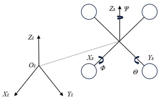
Figure 2.
Coordinate system and structure of a quadrotor UAV.
The lift required by the UAV is generated by the motors driving the rotor blades. Since all four rotor blades are fixed vertically and positioned in the same horizontal plane, the lift they generate is ideally directed vertically upwards relative to the plane of the fuselage. In the airframe coordinate system, this lift is denoted by . However, as the UAV operates in the world coordinate system, the lift must be transformed accordingly. The transformation between the airframe coordinate system and the world coordinate system is given by the following conversion:
Based on Newton’s second law and the force analysis of the drone, the following expression can be derived:
where , , and represent the accelerations in the x, y, and z directions, respectively. According to Euler’s equations, the moment balance equation for the UAV can be expressed as follows:
where represents the total moment acting on the UAV during flight, J is the inertia matrix, and denotes the angular velocity. The angular velocity equation of the UAV can be derived from Newton–Euler’s equations as follows:
where I represents the rotational inertia generated by the motors, l is the length of the quadrotor arm, and , , and correspond to the outputs of the UAV’s roll, pitch, and yaw channels, respectively. Given the complexity of the UAV system, the dynamics model has been optimized accordingly. The following optimizations are applied, taking into account the small angular variations and the slow rate of attitude change during the UAV’s flight:
The dynamic equations governing the motion of the quadrotor UAV are as follows:
where represents the distance from the center of the fuselage to each rotor, is the lift coefficient, and denotes the rotational speed of the rotors [31,32].
4. Attitude Control of a Dual Cascade MPC Based on Robust H-Infinity Control
Model Predictive Control (MPC) is a widely used technique in modern control theory, with significant applications in robotics, process control, autonomous driving, and UAVs. Its effectiveness stems from its ability to predict future behavior using a model, combine feed-forward and feedback control, and optimize in real time. The fundamental structure of MPC is illustrated in Figure 3.
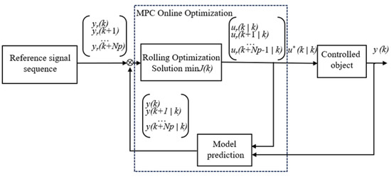
Figure 3.
Block diagram of MPC structure.
The stability of the UAV’s attitude is critical, especially when the quadrotor is disturbed by random airflow. If the attitude cannot be stabilized, the UAV risks crashing. To ensure stability under such disturbances, this paper proposes using a dual cascade MPC (Model Predictive Control) approach based on robust H-infinity control. In UAV attitude control, real-time adjustments can sometimes cause oscillations, while disturbances may only stabilize the UAV’s attitude after a brief period. Real-time adjustments could disrupt equilibrium, which is why the proposed controller sets the angular loop as the primary controller to manage the UAV’s attitude, while the angular velocity loop acts as a secondary controller. The control time of the angular loop is greater than the angular velocity loop. The attitude controller relies on MPC, which minimizes the prediction error relative to the control target through algorithmic optimization. To enhance the computational robustness of the MPC controller, the angular loop incorporates robust H-infinity control, which preprocesses the data before they are sent to the MPC controller. The design of this controller is illustrated in Figure 4 and Figure 5 below.
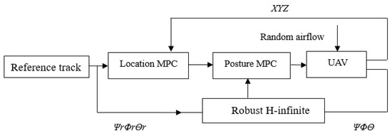
Figure 4.
Structure of UAV Attitude and Position Control.
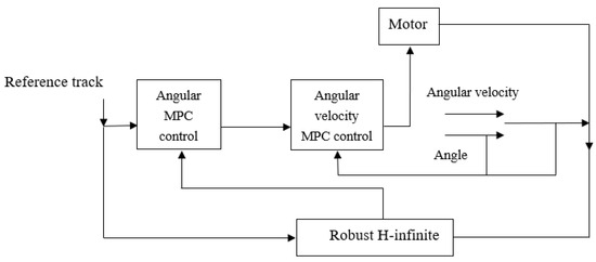
Figure 5.
Structure of robust H-infinity based dual cascade MPC control.
4.1. Robust Infinity Controller Setup
Before designing a robust H-infinity controller, it is often necessary to linearize the system to apply linear control theory [33]. Assuming the system operates near an equilibrium point, the nonlinear equations can be linearized to derive a state-space model as follows:
The attitude angle input matrix for the quadrotor UAV is denoted as X. The matrices , , , and represent the system’s state-space equation parameters, while corresponds to the perturbations affecting the UAV. These matrices are structured as follows:
represents the moments of inertia along the pitch, roll, and yaw axes, respectively, while denotes the control input for the attitude angles of the quadrotor UAV. The gain matrix of the robust H-infinity-horizon controller can be derived by solving the generalized algebraic Riccati equation, which is expressed as follows:
where X is the solution of the Riccati equation, and R and Q are the weight matrices. The robust H-infinity-horizon control law is derived from the solution of the Riccati equation, which is obtained by solving the following expression:
Here, K represents the gain matrix of the robust H-infinity-horizon controller. The output from this controller is subsequently used as feedback input for the MPC controller. The state-space model of the closed-loop system for the quadrotor UAV is as follows:
Since P is a constant matrix, P = 0, therefore the derivative of the Lyapunov function is calculated as follows:
Substitute the system’s state equation into the following:
Expand and combine like terms as follows:
Ensure robust performance by limiting the number of H-infinity paradigms with the following expression:
Substituting yields as follows:
To ensure the system remains stable in the presence of the disturbance d(t), while also meeting the requirements of H-infinity control, we introduce V to limit the impact of the disturbance on the system and establish a control condition such that the following is achieved:
This ensures that the Lyapunov function remains negative in the presence of disturbance d, guaranteeing the system’s stability. Substitute the expression as follows:
To ensure the inequality holds, the Schur complement is used to handle the cross term , converting it into a more manageable form.
The following can be concluded:
Substituting into the inequality of the Lyapunov equation’s derivative, we obtain the following:
To ensure the inequality holds, we need to ensure the following:
And ensures that , and the influence of the disturbance term is limited.
The above inequality indicates that the stability of the system is related to the selection of the Lyapunov matrix P, the control gain matrix K, and the disturbance matrix E. By setting the appropriate positive definite matrix P and gain matrix K to satisfy the above inequality, the system remains stable in the presence of disturbances.
4.2. Robust Controller Based MPC Angular Loop Setup
Based on the previous configuration of the robust H-infinity-horizon controller, the gain matrix K is used as the initial control rate to ensure that the system’s initial state is stabilized within a certain range. This is achieved by applying the constraints defined in Equation (21). The state-space equations governing the continuity of the quadrotor UAV’s attitude angle channel are as follows:
Here, is the input matrix for the quadrotor UAV’s attitude angle channel, while the output values in represent the pitch, roll, and yaw angles. The matrices , , and respectively represent the parameters of the system’s state-space equation. denotes the control input for the quadrotor UAV’s attitude angles.
Since the MPC controller operates on a discrete system, it is necessary to discretize the UAV’s attitude angle dynamics model. This is carried out by converting the continuous state-space equations of the system into a discrete state-space model for the quadrotor UAV’s attitude angle.
Here, , , and represent the state variables, control input variables, and control output variables of the nominal attitude angle system, respectively. represents the control rate output of the robust H-infinity-horizon controller . For the control input variables in the continuous-time state model and the discrete state model described above, the transformation relationship between the two is given as follows [34]:
where and denote the sampling time of the attitude angle and the control input matrix.
The difference equations for two consecutive moments of the quadrotor UAV’s attitude angle can be derived by calculating the difference between the state variables at these neighboring moments as follows:
It is possible to write the discrete state-space equations as an incremental model as follows:
The control increment for the attitude angle state can be derived from the following difference equation between two consecutive moments of the UAV’s attitude angle:
Here, these represent the state increment and control increment of the attitude angle. By substituting them into the differential equation of the quadrotor UAV, the incremental form of the differential equation can be obtained as follows:
For the nominal model of the attitude angle, the objective optimization function can be chosen as in the following equation:
The optimal control input sequence for the attitude angle at the Kth moment can be obtained as follows:
Simplifying the above equation yields the following:
For the system input value at the Kth moment shown in the equation above , the first element of the optimal input sequence can be selected. Thus, the system input expression can be formulated as follows:
Expand I and in the above equation to produce the following equation:
Finally, the actual control input expression for the attitude angle at moment t can be obtained through the following:
4.3. MPC Angle Ring Setting
The following kinematic equations for attitude angular velocity can be derived from the UAV’s mathematical model:
Then, the state-space equations of the attitude angle control system with perturbations are established as follows:
Format:
where the subsequent MPC controllers, such as and , are designed similarly to the angular ring setup.
The algorithm design structure is illustrated in Figure 6. The UAV’s desired output is transmitted to the MPC attitude loop via the differential form of the second-order reference model’s desired angle. Subsequently, the UAV’s angle and feedback value are sent to the robust H-infinity controller. The output from this controller, along with the desired attitude angle, is then fed into the MPC angle loop, which ultimately provides the output to the UAV.
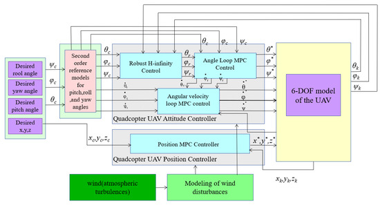
Figure 6.
Overall structure diagram of control algorithm.
5. Results
In this section, simulations are conducted to demonstrate the effectiveness of the proposed control method. The quadcopter UAV and its parameters used in the simulation are detailed in the table below.
The experiments focus on UAV trajectory tracking under random airflow interference conditions. Comparison algorithms are employed to verify the feasibility of the dual cascade MPC control method based on robust H-infinity control (referred to as H-MMPC), using MPC control algorithms and ADRC controllers. Table 2 presents some of the parameters used during the UAV simulation experiments for explanation.

Table 2.
Quadrotor UAV Simulation Parameters.
To verify the robustness of the designed controller, a simulation platform was developed in MATLAB R2022a. In the simulation, the perturbation was modeled as a composite wind field. Continuous, uninterrupted wind disturbances were applied to the UAV, with the maximum wind speeds of 2.7989 m/s and 2 m/s occurring at 2.9 s, 31.7 s, and 71.7 s, respectively. The random wind field disturbance curves for the quadcopter UAV are shown in Figure 7, while the controller’s response curves are displayed in Figure 8.
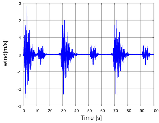
Figure 7.
Stochastic airflow disturbances.
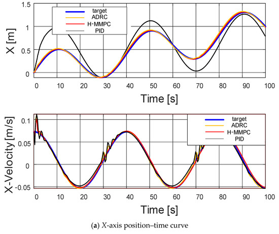
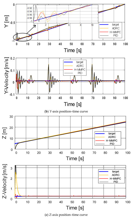
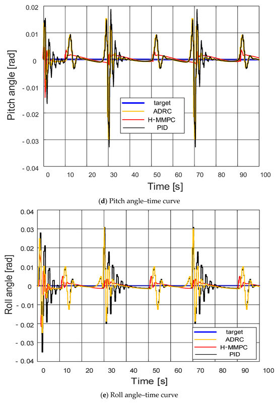
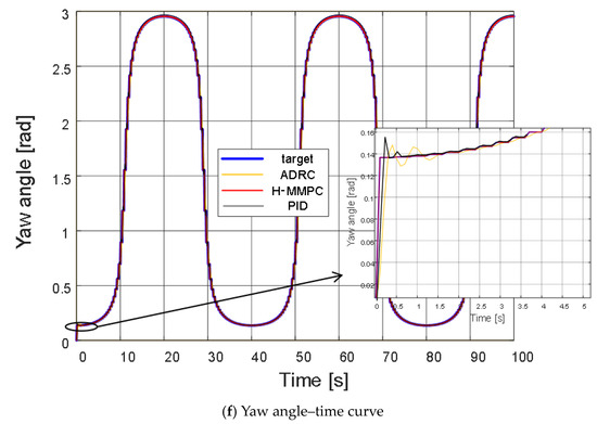
Figure 8.
Controller response curve.
Based on the experimental data waveforms, it can be concluded that the UAV experiences minor perturbations around 2.9 s, 31.7 s, and 71.7 s. However, the H-MMPC controller exhibits smaller perturbation amplitudes and shorter fluctuation durations compared to the ADRC and PID controllers. This is because the control algorithms in the position loop are the traditional MPC, ADRC, and PID controllers.
The H-MMPC controller design in the attitude loop clearly outperforms the ADRC and PID controllers, demonstrating superior robustness. Regarding the pitch angle–time curve, the H-MMPC controller shows reduced amplitude and jitter, with a shorter convergence time. This phenomenon is more pronounced in the roll angle–time curve, where amplitude fluctuations remain within 0.005, which is negligible for UAV operations. In contrast, the yaw angle–time curve shows that traditional ADRC and PID controllers exhibit initial jitter, while the H-MMPC controller stably follows the target curve, achieving satisfactory tracking.
Overall, the different control methods exhibit varying response speeds when adjusting to target angles. The H-MMPC consistently responds the fastest during perturbations and, along with ADRC, maintains closer alignment with the target curve, demonstrating superior stability. Conversely, the PID controller experiences significant fluctuations during perturbations, indicating a comparatively lower stability.
Figure 9 presents the position tracking curves of the quadrotor UAV for two algorithms in three-dimensional space, while Figure 10 displays the root mean square error (RMSE) curves for the UAV’s position along the X, Y, and Z axes, and the final RMSE values. As shown in Figure 9, when the UAV experiences random airflow disturbances, a small tracking error initially occurs. However, the controller successfully adjusts the UAV’s position over time, enabling it to maintain accurate tracking. The figure demonstrates that the proposed algorithm consistently restores stability more effectively than the ADRC and PID algorithms, with smaller fluctuation amplitudes following disturbances.
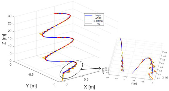
Figure 9.
Three-dimensional spatial tracking curves.
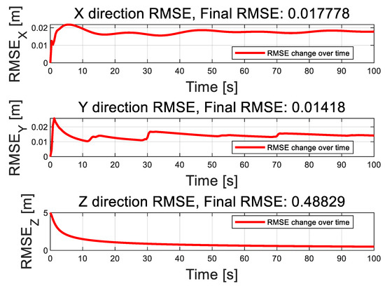
Figure 10.
Root Mean Square Error Curve of Position in XYZ Axis Direction.
Overall, H-MMPC responds rapidly during the initial phase, approaching the target trajectory more quickly than those of ADRC and PID, which exhibit significant deviations. During the spiraling phase, H-MMPC maintains superior tracking accuracy, while the PID controller exhibits noticeable deviations.
Figure 10 further illustrates that the proposed algorithm reduces the tracking errors along the X, Y, and Z axes, stabilizing at 0.017712, 0.013494, and 0.48828, respectively. Although random airflow disturbances cause corresponding fluctuations in the UAV’s position tracking error, the system ultimately converges and stabilizes itself.
Figure 11, Figure 12 and Figure 13 illustrate the root mean square error (RMSE) curves of the quadrotor UAV’s attitude angles. These figures show fluctuations in error at approximately 11, 30, 51, and 91 s, corresponding to moments when perturbation disturbances were introduced to simulate random airflow interference. Shortly after each disturbance, the UAV’s attitude stabilizes through controller adjustments. Following each error peak, the error rapidly decreases and tends toward zero, demonstrating the strong recovery capability of the proposed control algorithm. Apart from the fluctuations caused by the applied perturbations, the overall error remains remarkably consistently low, further emphasizing the algorithm’s excellent stability. See Figure 14, Figure 15 and Figure 16. It is the root mean square error curve of the attitude angle over time. The curve indicates that the UAV’s attitude control system experiences periodic errors under airflow disturbances. However, with the action of the UAV’s control system, the UAV eventually stabilizes, and the overall fluctuation amplitude always remains relatively small.
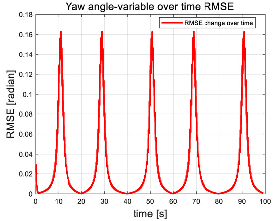
Figure 11.
Yaw angle root mean square error curve.
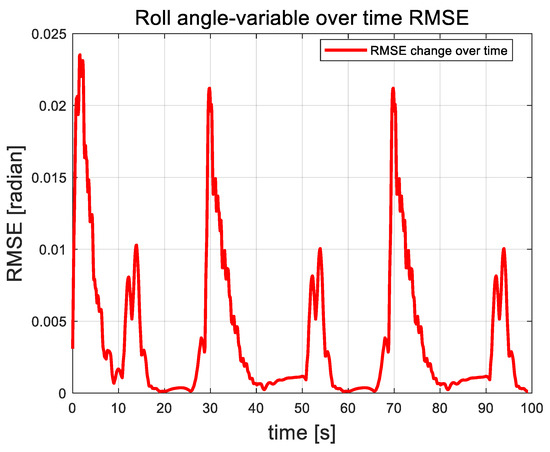
Figure 12.
Root mean square error curve of roll angle.
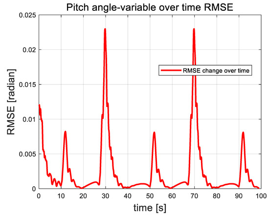
Figure 13.
Pitch angle rms error curve.
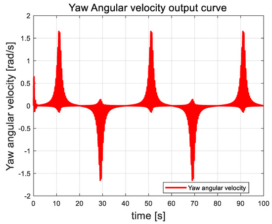
Figure 14.
Yaw angle angular velocity curve.
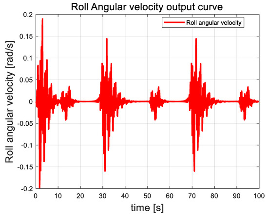
Figure 15.
Angular velocity curve of roll angle.
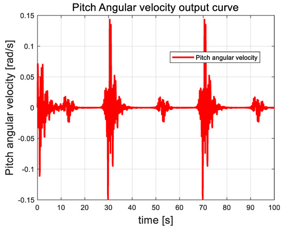
Figure 16.
Pitch angle angular velocity curve.
In this paper, the attitude angle of the quadrotor UAV is controlled as an auxiliary loop within the attitude control system. The overall trend of the angular velocity is closely correlated with external disturbances. As random airflow disturbances intensify, the angular velocity of the attitude angle fluctuates accordingly. This behavior contrasts with that of the attitude angle, which shows a distinct response. Once the UAV control system stabilizes, the angular velocity returns to zero and remains stable, showing no further fluctuations.
Table 3 compares the traditional PID algorithm, the ADRC algorithm, and the control method proposed in this study. The results demonstrate that our control algorithm significantly outperforms the traditional methods in terms of both response amplitude and reaction time. This improvement is primarily attributed to the cascade control strategy implemented. However, this strategy also introduces a considerable computational burden, increasing the overall complexity of the algorithm. Despite this, the performance gains suggest that the added complexity is justified. Future research will focus on optimizing the computational efficiency of the algorithm, aiming to reduce the processing load and simplify the control structure, making it a more practical and efficient solution.

Table 3.
The experimental results comparison and analysis.
6. Conclusions
This paper focuses on the self-balancing problem of a quadrotor UAV under random airflow disturbances. The control system is composed of the following two main loops: an attitude control loop and a position control loop. The position loop is designed using a traditional MPC controller, while the attitude loop employs a dual cascade MPC approach based on robust control to manage both the angle and angular velocity loops. The angle loop serves as the primary control loop for stabilizing the UAV’s attitude, using robust H∞ control to handle the attitude adjustments. The processed attitude data are then passed to the MPC controller, reducing its computational load. Through algorithmic optimization, the MPC minimizes the deviation between prediction errors and control targets. The angular velocity loop is managed using a traditional MPC control algorithm. Simulation results demonstrate that the proposed algorithm significantly enhances the robustness of the UAV’s flight attitude in the presence of random airflow disturbances.
Author Contributions
Conceptualization, Y.G.; methodology, Y.G., X.H., and N.H.; software, N.H. and B.W.; validation, Y.G., N.H., and B.W.; formal analysis, N.H.; investigation, X.H.; resources, B.W.; data curation, N.H.; writing—original draft preparation, Y.G.; writing—review and editing, N.H. and X.H.; visualization, Y.G.; supervision, N.H.; project administration, X.H.; funding acquisition, B.W. All authors have read and agreed to the published version of the manuscript.
Funding
This research was supported by the Shenyang Science and Technology Plan Project (No. 23-407-3-33).
Data Availability Statement
Data are contained within the article.
Acknowledgments
Thanks to teachers and lab colleagues for their support and help. Thanks for the professional reading of the reviewer.
Conflicts of Interest
The authors declare no conflicts of interest.
References
- Lei, Y.; Ming, X.C. Aerodynamic performance of hex-rotor UAV considering the horizontal airflow. Appl. Sci. 2019, 9, 4797. [Google Scholar] [CrossRef]
- Javaid, S.; Saeed, N.; Qadir, Z.; Fahim, H.; He, B.; Song, H.; Bilal, M. Communication and control in collaborative UAVs: Recent advances and future trends. IEEE Trans. Intell. Transp. Syst. 2023, 24, 5719–5739. [Google Scholar] [CrossRef]
- Aláez, D.; Olaz, X.; Prieto, M.; Villadangos, J.; Astrain, J.J. VTOL UAV digital twin for take-off, hovering and landing in different wind conditions. Simul. Model. Pract. Theory 2023, 123, 102703. [Google Scholar] [CrossRef]
- Lu, C.X.; Huang, Q. Design of the platform for a UAV flight control system based on STM32. Int. J. Digit. Content Technol. Its Appl. 2013, 7, 1033. [Google Scholar] [CrossRef]
- Chen, M.; Ma, H.; Kang, Y.; Wu, Q. Adaptive neural safe tracking control design for a class of uncertain nonlinear systems with output constraints and disturbances. IEEE Trans. Cybern. 2021, 52, 12571–12582. [Google Scholar] [CrossRef]
- Sahin, M.; Yavrucuk, I. Adaptive envelope protection control of wind turbines under varying operational conditions. Energy 2022, 247, 123544. [Google Scholar] [CrossRef]
- Li, B.; Gong, W.; Yang, Y.; Xiao, B.; Ran, D. Appointed fixed time observer-based sliding mode control for a quadrotor UAV under external disturbances. IEEE Trans. Aerosp. Electron. Syst. 2021, 58, 290–303. [Google Scholar] [CrossRef]
- Yang, Z.; Cheng, B. Fuzzy neural network dynamic inverse control strategy for quadrotor uav based on atmospheric turbulence. Appl. Sci. 2022, 12, 12232. [Google Scholar] [CrossRef]
- Zhang, H.; Yang, L. Position and attitude control based on single neuron pid with gravity compensation for quadrotor UAV. J. Aerosp. Technol. Manag. 2023, 15, e1023. [Google Scholar] [CrossRef]
- Niu, Z.; Yang, L.; Huang, Z.; Jiang, H. Design of Heading Adjustment System for Composite Wing UAV Based on PID Controller. In Proceedings of the 2023 IEEE International Conference on Unmanned Systems (ICUS), Hefei, China, 13–15 October 2023; pp. 1505–1511. [Google Scholar] [CrossRef]
- Xie, Z.; Li, Y.; Guan, Y.; Wei, C. Multi-UAV Sliding Mode Formation Control Based on Reinforcement Learning. In Proceedings of the 2021 5th Chinese Conference on Swarm Intelligence and Cooperative Control, Shenzhen, China, 19–22 January 2021; Springer Nature: Singapore, 2022; pp. 1628–1639. [Google Scholar] [CrossRef]
- Wang, X.; Mao, X. Non-overshooting sliding mode for UAV control. arXiv 2024, arXiv:2405.01087. [Google Scholar] [CrossRef]
- Chen, X.; Zhang, Q.; Liu, J. Extended State Observer-Based Saturation Integral Backstepping Control for Yaw Control of UAV Helicopters. Advances in Guidance, Navigation and Control. In Proceedings of the 2020 International Conference on Guidance, Navigation and Control, ICGNC 2020, Tianjin, China, 23–25 October 2020; Springer: Singapore, 2022; pp. 4021–4037. [Google Scholar] [CrossRef]
- Zhao, H.; Zhao, J.; Dong, X. UAV Swarm Formation Control Based on Disturbance Observer and Backstepping Controller. J. Phys. Conf. Series. IOP Publ. 2023, 2637, 012009. [Google Scholar] [CrossRef]
- Pang, Y.; Wang, Y.T.; Xia, H. Nonlinear generalized minimum variance tracking control of unmanned aircraft under the influence of wind disturbance. Control. Theory Appl. 2016, 33, 1155–1161. [Google Scholar] [CrossRef]
- Madebo, M.M.; Abdissa, C.M.; Lemma, L.N.; Negash, D.S. Robust Tracking Control for Quadrotor UAV with External Disturbances and Uncertainties Using Neural Network Based MRAC. IEEE Access 2024, 12, 36183–36201. [Google Scholar] [CrossRef]
- Oo, N.L.; Nay, L. Experimental investigation on turbulence effects on unsteady aerodynamics performances of two horizontally placed small-size UAV rotors. Aerosp. Sci. Technol. 2023, 141, 108535. [Google Scholar] [CrossRef]
- Bannwarth, J.X.; Kazemi, S.; Stol, K. Frequency-dependent control for wind disturbance rejection of a fully actuated UAV. Robotica 2024, 42, 1781–1795. [Google Scholar] [CrossRef]
- Wang, Q.; Wang, W.; Suzuki, S. UAV trajectory tracking under wind disturbance based on novel antidisturbance sliding mode control. Aerosp. Sci. Technol. 2024, 149, 109138. [Google Scholar] [CrossRef]
- Zhang, Q.; Wang, T.; Zhu, X. Fixed-time extended disturbance observer-based switching control of quadrotor UAV under marine wind conditions. Int. J. Dyn. Control 2024, 12, 1491–1501. [Google Scholar] [CrossRef]
- Muthusamy, P.K.; Suthar, B.; Muthusamy, R.; Garratt, M.; Pota, H.; Seneviratne, L.; Zweiri, Y. Self-organizing BFBEL control system for a UAV under wind disturbance. IEEE Trans. Ind. Electron. 2023, 71, 5021–5033. [Google Scholar] [CrossRef]
- Cai, Z.; Hao, Z.; Zhao, J.; Wang, Y. Obstacle Avoidance and Trajectory Tracking Control of a Quadrotor UAV Under Wind Disturbance. In Proceedings of the International Conference on Guidance, Navigation and Control, Xi’an, China, 12–14 August 2022; Springer Nature: Singapore, 2022; pp. 6053–6062. [Google Scholar] [CrossRef]
- Chen, C.; Zhang, X.; Peng, X. Trajectory tracking control of four-rotor UAV based on nonlinear extended state observer and model predictive control in wind disturbance environment. J. Phys. Conf. Ser. IOP Publ. 2024, 2764, 012075. [Google Scholar] [CrossRef]
- Li, B.; Zhu, X. A novel anti-disturbance control of quadrotor UAV considering wind and suspended payload. In Proceedings of the 2023 6th International Symposium on Autonomous Systems (ISAS), Tokyo, Japan, 1–3 November 2023; pp. 1–6. [Google Scholar] [CrossRef]
- Xu, Z.Q.; Lei, M. Command-filtered backstepping landing control for fixed-wing UAVs under wind disturbance. Comput. Simul. 2022, 39, 55–62. [Google Scholar]
- Liu, X.B.; Zhou, S.L.; Xiao, Z.C.; Qi, Y.H.; Dai, F.Y. Study on wind resistance of fixed-wing UAV tracking. Mod. Def. Technol. 2022, 50, 41. [Google Scholar] [CrossRef]
- Zhao, H.C.; Zhou, H.Q.; Wang, S.H. Quadrotor UAV sliding mode control based on expanded state observer. Command. Control. Simul. 2020, 42, 91–96. [Google Scholar]
- Zhang, J.Y.; Yu, C.M.; Ye, J.X. Trajectory tracking control of a quadrotor UAV based on dilated state observer and backstepping sliding mode method. Comput. Appl. 2018, 38, 2742–2746. [Google Scholar] [CrossRef]
- Sun, M.Y.; Bi, W.H.; Zhang, A.; Diao, Y.H. Quadrotor trajectory tracking control based on MPC and ESO-DO. Command. Control. Zhihui Kongzhi Yu Fangzhen 2024, 46, 104–114. [Google Scholar]
- Xue, J.Y.; Wang, B. Exponential time-varying gain backstepping sliding mode quadrotor attitude control. Control. Eng. 2022, 29, 935–943. [Google Scholar] [CrossRef]
- Samir, B.; Andk, N.; Roland, S. PID vs LQ Control Techniques Applied to an Indoor Micro Quadrotor. In Proceedings of the 2004 IEEE/RSJ International Conference on Intelligent Robots and Systems, Sendai, Japan, 28 September–2 October 2004; pp. 2451–2456. [Google Scholar] [CrossRef]
- Kemin, Z.; John, C.; Keith, G. Robust and optimal control. In Proceedings of the 35th IEEE Conference on Decision and Control, Kobe, Japan, 10–13 December 1996; pp. 1595–1598. [Google Scholar] [CrossRef]
- Yao, B.; Lu, P.; Yang, S.; Huang, X. Trajectory tracking controller based on PID-NLADRC. In Proceedings of the 2019 International Conference on Computer Network, Electronic and Automation (ICCNEA), Xi’an, China, 27–29 September 2019. [Google Scholar]
- Pounds, P.; Mahony, R.; Corke, P. Corke. Modelling and control of a quad- rotor robot. In Proceedings of the Australasian Conference on Robotics and Automation, Canberra, Australia, 4–6 December 2006; pp. 1–10. [Google Scholar]
Disclaimer/Publisher’s Note: The statements, opinions and data contained in all publications are solely those of the individual author(s) and contributor(s) and not of MDPI and/or the editor(s). MDPI and/or the editor(s) disclaim responsibility for any injury to people or property resulting from any ideas, methods, instructions or products referred to in the content. |
© 2024 by the authors. Licensee MDPI, Basel, Switzerland. This article is an open access article distributed under the terms and conditions of the Creative Commons Attribution (CC BY) license (https://creativecommons.org/licenses/by/4.0/).