Abstract
Soft robotics has emerged as a promising field due to the unique characteristics offered by compliant and flexible structures. Overcoming the challenge of precise position control is crucial in the development of such systems that require accurate modeling of soft robots. In response, a hybrid-actuated soft robot employing both air pressure and tendons was proposed, modeled, and validated using the dynamic Cosserat rod theory. This approach comprehensively addresses various aspects of deformation, including bending, torsion, shear, and extension. The designed robot was intended for robot-assisted cardiac ablation, a minimally invasive procedure that is used to treat cardiac arrhythmias. Within the framework of the Cosserat model, dynamic equations were discretized over time, and ordinary differential equations (ODEs) were solved at each time step. These equations of motion facilitated the prediction of the robot’s response to different control inputs, such as the air pressure and tension applied to the tendons. Experimental studies were conducted on a physical prototype to examine the accuracy of the model. The experiments covered a tension range of 0 to 3 N for each tendon and an air pressure range of 0 to 40 kPa for the central chamber. The results confirmed the accuracy of the model, demonstrating that the dynamic equations successfully predicted the robot’s motion in response to diverse control inputs.
1. Introduction
1.1. Background
Cardiac abnormalities have been widely recognized as a significant contributing factor to hospitalization and mortality worldwide. Arrhythmias, characterized by disruptions in heart rhythm resulting from changes in the electrical conduction system, represent the second most commonly observed clinical occurrence of cardiovascular abnormalities [1]. Atrial fibrillation (AFib), the most prevalent type of arrhythmia, exhibits the highest incidence rate [2]. The primary cause of AFib is the imbalanced discharge of signals originating from the pulmonary veins (PVs), leading to severe cardiovascular complications. Extensive research has demonstrated that individuals diagnosed with AFib face a risk of stroke incidence over five times higher than those without AFib [3].
Ablation catheters, which are long and flexible medical devices, have emerged as a prominent treatment approach for stabilizing arrhythmia rates. Previous studies have indicated that the utilization of catheter-based ablation procedures was associated with a low risk of complications during the periprocedural phase and demonstrated a favorable safety profile [4]. During the ablation procedures, the ventricular muscles responsible for causing undesirable pulses or movements in the heart were disabled through either freezing or burning. Among the different modalities of ablation, radio frequency ablation (RFA) had been considered the most favorable option. Nevertheless, the efficacy of RFA relied heavily on the size of the lesion created during the ablation process [5]. Figure 1 illustrates the configuration of a hybrid-actuated soft robot functioning as a catheter within a patient’s heart during RFA ablation.
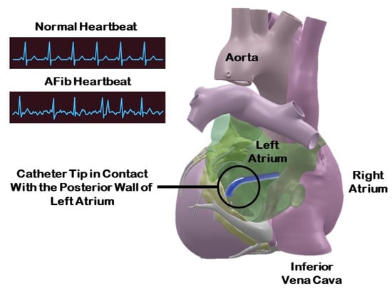
Figure 1.
Representation of a hybrid-actuated soft robot during RFA ablation (3D heart model from Zygote Media Group Inc. with permission).
Robot-assisted catheter intervention (RCI) represents state-of-the-art technology used to treat cardiac abnormalities [6,7]. The introduction of robotic catheterization aimed to mitigate the risks associated with traditional manual intervention methods [8,9]. However, the currently available catheters have a fixed stiffness and utilize rigid instruments [10]. Adjusting the stiffness between the instrument and the organ within the patient’s body is necessary during the manipulator’s intervention for treatment or diagnosis to ensure a safe procedure [11]. Previous research has demonstrated that the efficacy of RFA is closely related to maintaining the catheter-tissue contact force within a range of 10 to 30 grf [12]. To address this challenge, recent studies have shown that soft robots can provide a range of stiffness options during an intervention, thereby ensuring the procedure’s safety [13,14,15].
1.2. Hybrid-Actuated Soft Robots
Soft slender objects have gained increasing interest in the field of surgical robotics, particularly in the context of soft manipulators [16,17,18] and soft sensors [19,20]. Although several studies have highlighted the effectiveness of a single-actuation modality, such as pneumatic actuators [21], with reinforced soft actuators [22], and pNet actuators [23]; hybrid-actuation was investigated to overcome the limitations associated with single-actuation methods. From a design perspective, one major difference between this work and previous studies (such as soft robots with reinforcements) is that tendons wrapped around the outer diameter of the soft robot were used to provide constraints for achieving different modes of actuation (i.e., bending, extension, and twist). Here, the tendons are passed internally and tied at the tip of the soft robot to enable bending in 3D. The hybrid actuation method consists of integrating two or more different driving modalities with the intent of augmenting the load-bearing capacity and precision of control exhibited by flexible manipulatory systems. An illustrative example of such a hybrid-actuation mode is the combination of the fluid-actuation mode alongside the cable-actuation mode. The fluid-actuation mode demonstrated favorable characteristics in pressure bearing while exhibiting relatively weak performance in tensile bearing. In contrast, the cable-actuation mode offered robust tensile bearing while being limited in its capability to withstand compressive forces. Through the integration of these two different driving modalities, flexible manipulators stand to gain from both their pressure-bearing and tensile-bearing attributes, resulting in an amplification of load capacity and improved position control accuracy.
While recent research has focused on the inverse approach for force estimation [24,25] to provide surgeons with haptic feedback, forward dynamic models are essential for modeling and developing soft robot designs and control schemes, as well as studying dynamic events like catheterization in real-world scenarios. In surgical interventions, accounting for sudden dynamic movements is crucial, even when the system exhibits minimal inertia effects and acceleration. Such unexpected movements can significantly impact procedural outcomes and jeopardize patient safety. Thus, a real-time dynamic model that can anticipate and compensate for these movements becomes indispensable. Incorporating a dynamic equation enables us to account for the heartbeat’s rhythm, allowing us to accurately simulate and model cardiac ablation. Moreover, the dynamic equations provide temporal aspects of the procedure, such as the deformation of the soft robot in response to changing inputs and boundary conditions. Dynamic movements primarily arise from the structure of the robot, the loading conditions, and the discontinuous changes in loading, rendering quasi-static assumptions inadequate for accurately estimating deformations in soft robots [26]. Numerous approaches have been proposed in the literature for the dynamic modeling of soft robots [27,28]. For instance, the piecewise constant curvature (PCC) representation has been employed to model robot shapes [29,30]. However, under the consideration of external loads or inertial dynamics, a constant curvature representation may no longer be sufficient due to torsion, shear, extension, or variations in curvature. To address this challenge, a Cosserat-based dynamic formulation for hybrid-driven soft robots under general loading conditions was introduced. A key contribution of this study lies in the derivation of a set of dynamic partial differential equations (PDEs) for a soft robot that is actuated simultaneously by air pressure and tendons. The principal distinction from the prior research [13] lies in the incorporation of the time-dependent parameter within the Cosserat rod model. Furthermore, despite differences in the intended surgical application, the kinematic, material modeling, and governing equations of motion differ from the previous study. The governing equations of motion for a slender soft robot are presented in Section 2, followed by a proposed representation of the forces and moments generated by tendons and an air chamber. Furthermore, a linear constitutive model is employed to establish a relationship between the loadings and the material properties of the soft robot. By discretizing time, the set of PDEs is transformed into a system of ordinary differential equations (ODEs), enabling the estimation of the soft robot’s shape based on known boundary conditions (BCs). In Section 3, the obtained results are presented and discussed in conjunction with the theoretical framework, allowing for a comprehensive comparison.
2. Materials and Methods
2.1. Dynamic Model of a Hybrid-Actuated Soft Robot
2.1.1. Governing Equations of Motion
Slender objects can be effectively represented as one-dimensional structures, with their state variables being expressed as functions of time t and an arc length parameter , where L denotes the length of the soft robot. In this study, the soft robot is equipped with a central channel to regulate air pressure, along with m pathways to accommodate the passage of tendons. The configuration of the robot’s cross section, depicted in Figure 2, serves to illustrate the arrangement of the air chamber and tendons, where r represents the radius of the backbone, and indicates the offset of the tendons from the central axis. In this study, bolded parameters represent vectors, while non-bolded parameters denote scalars. When the air chamber is inflated, and the tendons are tensioned, the backbone of the robot becomes subject to various forces and moments. Consequently, this results in deformation, which can be accurately described using the Cosserat rod model. The dynamic response of the robot is dependent upon its mechanical properties as well as the external loads applied to it. As a general principle, a Cosserat rod is characterized by the curve of its centerline, denoted as , as well as a rotation matrix, denoted as . Moreover, in the local frame, the rate of the positional change with respect to the arc length is represented by , while the curvature is defined by [31]:
where is the transpose of vector, in which is a dummy symbol (same for ), and operator maps to . For a typical vector [32],
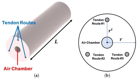
Figure 2.
Hybrid-actuated soft robot. (a) Air chamber and tendons routes, (b) cross section of the soft robot in which r is the backbone radius, and is the tendons’ offsets.
The linear velocity and angular velocity in the local frame can also be calculated using the time derivation of the centerline curve and orientation matrix as [31]:
An arbitrary element of the rod with the corresponding parameters is illustrated in Figure 3. In this figure, the z-axis is aligned with the backbone of the soft robot in its initial straight position. By assuming a constant tendon tension along the length and fixed tendon locations relative to the robot’s cross section during deformation, the PDEs that govern the dynamic response of a soft robot in the global coordinate frame were formulated [31]:
where and are the internal force and moment in the global frame, and are the general distributed external force and moment, A is the soft robot cross-sectional area, is the material density, and is the second mass moment of inertia tensor:
in which are the second moment of area. For a circular rod, with soft robot radius r, and . Also, the general force and moment terms in (4) can be defined as:
where and represent the distributed force and moment components arising from the tendon tension that were tied in the tip of the soft robot, while and denote the distributed force and moment components attributed to central air pressure. Additionally, and refer to any other external distributed force and moment components that might be considered later, respectively. The expression for the tendon force and moment can be derived in relation to the backbone kinematic parameters, as detailed in [33]:
in which:
where is the representation of the variable in the local frame, (i.e., and is the tendon tension. Air pressure forces always act normally on a cross-sectional plane. Thus, distributed forces () and moments () due to the air chamber can be considered as:
where P and are the uniform pressure and cross section area of the air chamber, respectively. Also, is the unit vector (). The term together represents the force amount generated due to the air pressure at the cap of the soft robot. Lastly, the external distributed forces can be considered as gravitational and air drag resistance forces; thus, :
where is the gravitational acceleration vector, is the square-law-drag damping coefficient, and ⊙ is the Hadamard product.
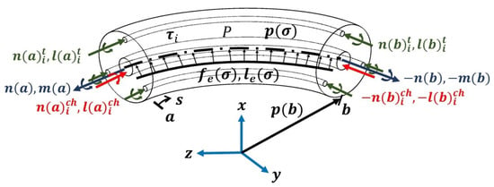
Figure 3.
An arbitrary element of the hybrid-actuated soft robot subject to distributed forces and moment at the time t.
2.1.2. Material Constitutive Law
The dynamic system, governed by (4), had independent variables and . Therefore, it was necessary to implement a material constitutive law to establish the relationship between these variables and the internal loadings. By combining the Cosserat rod model with the appropriate constitutive laws, a set of PDEs was derived to describe the dynamic response of the system. For the purposes of this study, the backbone of the system was assumed to be composed of elastic materials, and a linear elasticity law with material damping was employed [31]:
where and corresponded to the initial posture of the rod when and , respectively. For a rod that is initially straight in z-direction, , and . Also, is the stiffness matrix for the shear and extension, and is the stiffness matrix for the bending and torsion, in which E is the Young’s modulus, G is the shear modulus, in which , where is Poisson’s ratio. Also, and are coefficients for the Kelvin–Voigt-type viscous damping [34].
2.1.3. Boundary Conditions
Consider a soft robot with three tendons and a central air chamber in a cantilever configuration (Figure 4). Tendons that are terminated at the distal end as well as the cap of the air chamber will contribute to the BCs. As tendon tension is always and anywhere tangent to the posture, the clamp-free soft robot BCs would be:
where proximal position, and is the identity matrix. The shooting method was employed to solve the Boundary Value Problem (BVP) iteratively by estimating the unknown initial values. Subsequently, the guessed values were iteratively adjusted using a selected nonlinear optimization routine to minimize the residual error of the distal BCs until they reached zero.
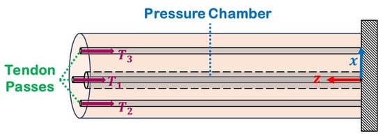
Figure 4.
Cantilever configuration of a hybrid-actuated soft robot.
2.1.4. Semi-Discretization in Time for the General PDE Solution
By substituting the formulas of implicit differentiation for all the time derivative terms in (4), a set of ODEs could be derived. Given the initial configuration of the robot, the dynamic simulation loop was initiated, and the problem was iteratively solved in the time domain. In order to achieve this, Backward Differentiation Formulas of order (BDF-) were employed for the implicit approximation of time derivatives [35]. Additionally, the shooting method utilizing MATLAB’s fsolve function and the forward Euler method for spatial integration were employed. The time derivatives of any state variables y could be calculated as follows:
in which:
with representing the coefficient associated with the BDF- method, and denoting the time increment. The iterative solution of the ODE set, along with the corresponding BCs, was carried out by implementing Euler’s method. The current problem encompassed four BCs, specifically pertaining to the variables , , , and , at the proximal end, while the remaining BCs for and were present at the distal end.
2.2. Experimental Setup
Consideration was given to a tendon-driven pneumatic-actuated soft robot comprising a central chamber and three tendons positioned angularly around the backbone, separated by a fixed angle of 120. The soft robot had an outer diameter of 12 mm. The design consisted of a central chamber with a diameter of 3 mm. The tendon passages possessed a diameter of 1.5 mm, while the tendons were offset by 4 mm. The pertinent model parameters employed to solve the set of equations outlined in (4) during the study are summarized in Table 1. Initially, the rod was assumed to be straight, thus establishing a correlation between the initial conditions and the rod’s straight posture.

Table 1.
Model parameters of the soft robot.
The fabrication process of the soft robot was conducted by employing a 3D printer (Replicator+, MakerBot, New York, NY, USA) to swiftly produce a cylindrical mold with internal passages, designed to accommodate the chamber and tendons. Additionally, a 3D-printed housing platform was created to facilitate the installation of the soft robot’s base into the aluminum frame. The body of the soft robot was constructed using Ecoflex 00-50 (Smooth-On Inc., Macungie, PA, USA ), a silicone mixture comprising two parts, A and B, in a 1:1 ratio. This mixture underwent degassing in a vacuum chamber and was subsequently allowed to cure for a duration of 24 h at a temperature of 24 °C. To supply air pressure, an air pump (KOGE KPM27W, DC 6.0V, Taipei, Taiwan) was utilized, while a pressure sensor (Phidgets Inc., Calgary, Alberta, Canada) was employed to record the real-time pressure measurements within the chamber throughout the experiment. The precise regulation of the internal air pressure in the central chamber of the soft robot was achieved through the utilization of an electronic pressure regulator (ITV0010-3UML, SMC, Noblesville, IN, USA). Monitoring the position of the soft robot’s tip was achieved by an electromagnetic motion tracker (Microsensor 1.8 mm, Polhemus, Colchester, VT, USA), which was securely attached to the tip of the soft robot. Additionally, the experimental configuration integrated three motors (Maxon, EC 45 flat, 60 W, Sachseln, Switzerland) and a digital positioning controller (Maxon, EPOS4 Compact, Sachseln, Switzerland) to control the tendon force at the soft robot’s tip. For precise control, the coefficients of the PID controller were tuned before the experiments. These motors were linked to a power supply (24 V, 10 A). Figure 5 depicts the experimental setup employed in this study.
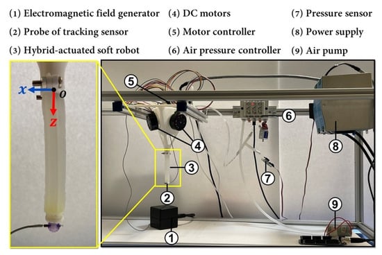
Figure 5.
Description of the mechanical and electrical components used to prototype a hybrid-actuated soft robot.
Furthermore, a C# program was meticulously developed to facilitate the acquisition and regulation of the pneumatic pressure and motor torque. The motors’ torque control was effectively accomplished by employing Maxon’s software development kit and harnessing the inherent proportional–integral controller of the motor driver. To accurately estimate the tension of the tendons, the pulley’s diameter was incorporated in conjunction with the motor torque control capabilities provided by the aforementioned software. In the validation study, a series of fifteen experiments were conducted to investigate the influence of the chamber pressure and tendon tension on the deformation of a soft robot. The experiments involved varying the chamber pressures from 0 kPa to 40 kPa and the tendon forces from 0 N to 3 N. To enhance the reliability of the findings, each experiment was repeated three times, and the average measurements were recorded. Throughout each experiment, the tendon forces were gradually increased from 0 N to 3 N while maintaining a constant pressure inside the air chamber. As the tendon forces increased, the soft robot underwent deformation from its initial resting position. Upon reaching the maximum force of 3 N, the first tendon was released, causing the tip of the soft robot to return to its original position. This process was repeated for the second and third tendons. The experiments were further repeated under four different internal chamber pressures: 10, 20, 30, and 40 kPa. The experimental validation methodology employed in this study is presented in Table 2.

Table 2.
Experimental validation methodology.
During each experiment, the tip position of the soft robot was recorded by the magnetic tracking sensor to facilitate a comparison with the results obtained from the Cosserat model. These recorded positions were subsequently evaluated against the ground truth data in order to ascertain the accuracy of the model. The results provided strong evidence that the deformations exhibited by the soft robot were consistent with the predictions of the established model. As depicted in Figure 6, the configuration of the soft robot was illustrated, showcasing its initial shape and the impact of a 3 N tendon tension on each motor individually, while applying an internal chamber pressure of 10 kPa. The analysis conducted in the subsequent section revealed that, under fixed conditions of internal chamber pressure and tendon tension, the soft robot consistently demonstrated similar deformation patterns. This finding further bolstered the alignment between the soft robot’s behavior and the anticipated outcomes outlined by the Cosserat model. Furthermore, Figure 7 illustrates the tip trajectory of the hybrid-actuated soft robot, providing a visual representation of its motion characteristics. The depicted trajectory served as supplementary evidence supporting the alignment between the observed behavior of the soft robot and the predictions derived from the model. Through the comprehensive analysis of experimental results and a thorough examination of the soft robot’s behavior, it was convincingly demonstrated that the deformations of the soft robot were in accordance with the expectations established by the Cosserat model.
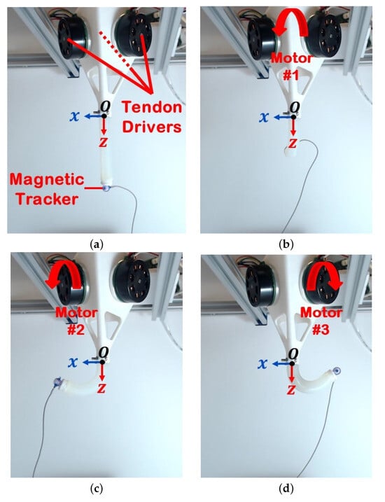
Figure 6.
(a) Initial shape and (b–d) the effect of 3 N tendon tension on each motor while applying a 10 kPa of internal chamber pressure on the deformation of the soft robot.
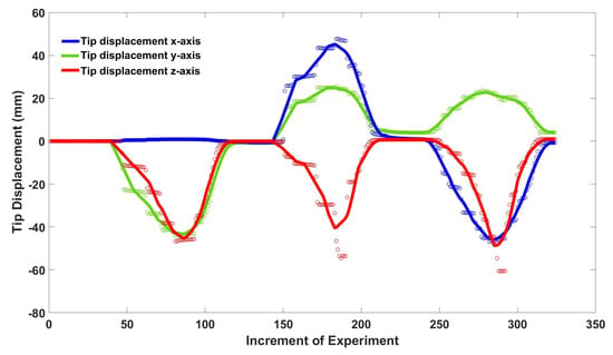
Figure 7.
Tip trajectory of the hybrid-actuated soft robot as three tendons were successively pulled at 3 N each, maintaining a constant chamber pressure of 10 kPa in the x, y, and z-axes. The white dots represent the precise measured values for the tip of the soft robot in the x, y, and z components, obtained using the magnetic tracker probe.
3. Results and Discussion
Hysteresis characteristics usually play a role in evaluating the performance of soft actuators [36]. These characteristics, commonly identified in soft robotic systems, denote the delay or lag in the material’s response to changes in input stimuli. While investigating hysteresis is vital for refining the design and control of soft robots, it is worth noting that the observed amount of hysteresis during the experiments had a negligible impact. Figure 8 shows the test data and working space of the soft robot. As can be seen in Figure 8a, first, the internal pressure of the air chamber was set to a constant amount, and then the tip of the soft robot was pulled in the x-axis. Then, the robot returned to its initial position, and the second tendon, which was tied at a 120 with respect to the first tendon, was pulled. The same procedure was repeated for the third tendon. Figure 8b shows the total working space of the tip of a soft robot that can be achieved through the simultaneous pulling of the three tendons. The comparison between the theoretical predictions from the Cosserat model and experimental measurements demonstrated a low relative Mean Absolute Error (MAE) in relation to the length of the robot, indicating the model’s ability to accurately predict the behavior of the hybrid-actuated soft robot.
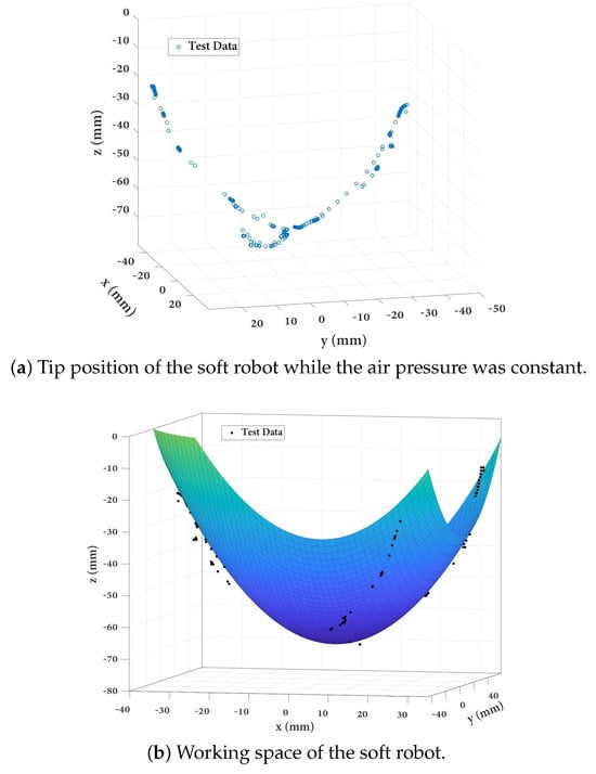
Figure 8.
Test data from the experiments. (a) Tip position of the soft robot, and (b) working space of the hybrid-actuated soft robot in the x, y, and z-axes.
This suggests that the model is a reliable tool for analyzing and predicting the deformations of the entirely soft robot. However, it is essential to acknowledge that the results may not fully encompass all the phenomena observed in the experimental measurements. This limitation stems from the exclusion of the viscoelastic behavior of the soft material, which was not considered in the material model. The neglected viscoelastic properties could potentially introduce additional complexities and affect the accuracy of the predictions.
The findings further demonstrated the validity and applicability of the Cosserat model in describing the dynamic movements of soft robots. Figure 9 illustrates the 3D deformation of the soft robot, as simulated through the implementation of the Cosserat rod model. The individual X and Y components corresponding to each case are presented in Figure 9b–d. It is evident that upon exerting tension along the x-axis, the Y displacement component approaches insignificance. Conversely, in scenarios where the remaining two tendons were pulled, each separated by an angular span of 120, the Y displacement components exhibit a symmetrical opposition to one another.
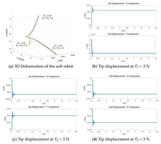
Figure 9.
(a) Three-dimensional deformation of the soft robot under three different tendon tensions. (b–d) X and Y components of the tip displacement when the tension in a single tendon is set to 3 N, while the tension in the other tendon is set to zero.
The findings outlined in this research enhanced the understanding of integrating air pressure into the Cosserat rod model simultaneously by the presence of the tendon tensions. This integration is achieved firstly by encompassing this pressure within the framework of internal forces and moments and secondly by accounting for the force generated at the cap of the soft robot, resulting from its internal pressure. By incorporating pressure into the internal forces and moments of the Cosserat rod model, this study not only addresses an important aspect of soft robot mechanics but also enriches the model’s accuracy and predictive capabilities. On the other hand, in practical applications of robot-assisted cardiac ablation, the soft robot’s navigation can be precisely achieved by independently actuating tendons through three motors. It is also possible to manipulate the air pressure along the central channel simultaneously, making it a promising tool with adjustable stiffness. Next, the estimation of the tip position using the dynamic Cosserat model, given the loading and boundary conditions, can also be achieved. Moreover, the potential for miniaturization exists, as the actuation components such as the motors and pressure supply are located outside the patient’s body.
4. Conclusions
This study presented a dynamic formulation of the Cosserat rod in the context of a hybrid-actuated soft robot, focusing on predicting its deformation under varying air pressures and tendon tensions for use in robot-assisted cardiac ablation. By incorporating the effects of internal pressure into the dynamic formulation, this approach extends the existing literature in this field. The accuracy of the proposed model was confirmed through experimental validation across multiple scenarios. The model formulated in this study can subsequently be applied to implement model-based control of the soft robot. For future work, the geometry of the soft robot will be optimized to mitigate unnecessary side deformation and increase the axial exertion load. This optimization process involves seeking a compromise between the offset of the tendon and the aspect ratio of the soft robot. Advanced computational techniques, such as parametric finite element analysis and optimization algorithms, will be utilize to progressively refine the geometry of the soft robot. The ultimate objective of this optimization effort will be to develop a soft robot with enhanced structural integrity, augmented load-bearing capacity, and superior controllability. Additionally, considering the material nonlinearity associated with the soft robot made of silicon material, such as hyperelasticity, a potential extension of the current work could involve incorporating a material model, like the two-term Mooney–Rivlin model, into the existing set of dynamic equations presented in the current study.
Author Contributions
Conceptualization, M.R. and A.H.; methodology, M.R. and A.H.; software, M.R. and A.H.; validation, M.R.; formal analysis, M.R.; investigation, M.R.; resources, J.D. and A.H.; data curation, M.R.; writing—original draft preparation, M.R.; writing—review and editing, M.R., J.D. and A.H.; visualization, M.R.; supervision J.D.; project administration, A.H.; funding acquisition, J.D. All authors have read and agreed to the published version of the manuscript.
Funding
This research was supported by the Natural Science and Engineering Research Council (NSERC) of Canada through the NSERC CREATE Grant for Innovation-at-the-Cutting-Edge (ICE), the Fonds de Recherche du Québec pour la Nature et les Technologies (FRQNT), Concordia University, and McGill University, Montreal, QC, Canada.
Institutional Review Board Statement
Not applicable.
Informed Consent Statement
Not applicable.
Data Availability Statement
Data are contained within the article.
Conflicts of Interest
The authors declare no conflicts of interest.
Abbreviations
The following abbreviations are used in this manuscript:
| AFib | Atrial Fibrillation |
| BC | Boundary Condition |
| BDF | Backward Differentiation Formulas |
| BVP | Boundary Value Problem |
| PCC | Piecewise Constant Curvature |
| PDE | Partial Differential Equation |
| PV | Pulmonary Vein |
| RCI | Robot-assisted Catheter Intervention |
| RFA | Radio Frequency Ablation |
| MAE | Mean Absolute Error |
| ODE | Ordinary Differential Equation |
References
- Podrid, P.J.; Myerburg, R.J. Epidemiology and stratification of risk for sudden cardiac death. Clin. Cardiol. Int. Index. Peer-Rev. J. Adv. Treat. Cardiovasc. Dis. 2005, 28, 3–11. [Google Scholar] [CrossRef] [PubMed]
- Cofiño-Fabres, C.; Passier, R.; Schwach, V. Towards Improved Human In Vitro Models for Cardiac Arrhythmia: Disease Mechanisms, Treatment, and Models of Atrial Fibrillation. Biomedicines 2023, 11, 2355. [Google Scholar] [CrossRef] [PubMed]
- Deedwania, P.C.; Lardizabal, J.A. Atrial fibrillation in heart failure: A comprehensive review. Am. J. Med. 2010, 123, 198–204. [Google Scholar] [CrossRef] [PubMed]
- Gupta, A.; Perera, T.; Ganesan, A.; Sullivan, T.; Lau, D.H.; Roberts-Thomson, K.C.; Brooks, A.G.; Sanders, P. Complications of catheter ablation of atrial fibrillation: A systematic review. Circ. Arrhythmia Electrophysiol. 2013, 6, 1082–1088. [Google Scholar] [CrossRef] [PubMed]
- Beinart, R.; Abbara, S.; Blum, A.; Ferencik, M.; Heist, K.; Ruskin, J.; Mansour, M. Left atrial wall thickness variability measured by CT scans in patients undergoing pulmonary vein isolation. J. Cardiovasc. Electrophysiol. 2011, 22, 1232–1236. [Google Scholar] [CrossRef] [PubMed]
- Duan, W.; Akinyemi, T.; Du, W.; Ma, J.; Chen, X.; Wang, F.; Omisore, O.; Luo, J.; Wang, H.; Wang, L. Technical and Clinical Progress on Robot-Assisted Endovascular Interventions: A Review. Micromachines 2023, 14, 197. [Google Scholar] [CrossRef] [PubMed]
- Hooshiar, A.; Najarian, S.; Dargahi, J. Haptic telerobotic cardiovascular intervention: A review of approaches, methods, and future perspectives. IEEE Rev. Biomed. Eng. 2019, 13, 32–50. [Google Scholar] [CrossRef]
- Nguyen, C.C.; Thai, M.T.; Hoang, T.T.; Davies, J.; Phan, P.T.; Zhu, K.; Wu, L.; Brodie, M.A.; Tsai, D.; Ha, Q.P.; et al. Development of a soft robotic catheter for vascular intervention surgery. Sens. Actuators A Phys. 2023, 357, 114380. [Google Scholar] [CrossRef]
- Jolaei, M.; Hooshiar, A.; Dargahi, J.; Packirisamy, M. Toward task autonomy in robotic cardiac ablation: Learning-based kinematic control of soft tendon-driven catheters. Soft Robot. 2021, 8, 340–351. [Google Scholar] [CrossRef]
- Ren, B.; Zhao, Y.; Zhang, J.; Li, H.; Li, K.; Zhang, J. The critical technologies of vascular interventional robotic catheterization: A Review. IEEE Sens. J. 2023, 23, 30051–30069. [Google Scholar] [CrossRef]
- Thai, M.T.; Phan, P.T.; Hoang, T.T.; Wong, S.; Lovell, N.H.; Do, T.N. Advanced intelligent systems for surgical robotics. Adv. Intell. Syst. 2020, 2, 1900138. [Google Scholar] [CrossRef]
- Okumura, Y.; Johnson, S.B.; Bunch, T.J.; Henz, B.D.; O’BRIEN, C.J.; Packer, D.L. A systematical analysis of in vivo contact forces on virtual catheter tip/tissue surface contact during cardiac mapping and intervention. J. Cardiovasc. Electrophysiol. 2008, 19, 632–640. [Google Scholar] [CrossRef] [PubMed]
- Roshanfar, M.; Taki, S.; Sayadi, A.; Cecere, R.; Dargahi, J.; Hooshiar, A. Hyperelastic Modeling and Validation of Hybrid-Actuated Soft Robot with Pressure-Stiffening. Micromachines 2023, 14, 900. [Google Scholar] [CrossRef] [PubMed]
- Roshanfar, M.; Sayadi, A.; Dargahi, J.; Hooshiar, A. Stiffness adaptation of a hybrid soft surgical robot for improved safety in interventional surgery. In Proceedings of the 2022 44th Annual International Conference of the IEEE Engineering in Medicine & Biology Society (EMBC), Glasgow, UK, 11–15 July 2022; pp. 4853–4859. [Google Scholar]
- Roshanfar, M.; Dargahi, J.; Hooshiar, A. Toward semi-autonomous stiffness adaptation of pneumatic soft robots: Modeling and validation. In Proceedings of the 2021 IEEE International Conference on Autonomous Systems (ICAS), Montreal, QC, Canada, 11–13 August 2021; pp. 1–5. [Google Scholar]
- Polygerinos, P.; Correll, N.; Morin, S.A.; Mosadegh, B.; Onal, C.D.; Petersen, K.; Cianchetti, M.; Tolley, M.T.; Shepherd, R.F. Soft robotics: Review of fluid-driven intrinsically soft devices; manufacturing, sensing, control, and applications in human-robot interaction. Adv. Eng. Mater. 2017, 19, 1700016. [Google Scholar] [CrossRef]
- Mosadegh, B.; Polygerinos, P.; Keplinger, C.; Wennstedt, S.; Shepherd, R.F.; Gupta, U.; Shim, J.; Bertoldi, K.; Walsh, C.J.; Whitesides, G.M. Pneumatic networks for soft robotics that actuate rapidly. Adv. Funct. Mater. 2014, 24, 2163–2170. [Google Scholar] [CrossRef]
- Yu, Y.; Fu, T. Design and Experimental Study of Cavity Structure of Pneumatic Soft Actuator. Actuators 2023, 12, 314. [Google Scholar] [CrossRef]
- Torkaman, T.; Roshanfar, M.; Dargahi, J.; Hooshiar, A. Embedded Six-DoF Force–Torque Sensor for Soft Robots With Learning-Based Calibration. IEEE Sens. J. 2023, 23, 4204–4215. [Google Scholar] [CrossRef]
- Lahcen, A.A.; Caprio, A.; Hsue, W.; Tschabrunn, C.; Liu, C.; Mosadegh, B.; Dunham, S. Creating Stretchable Electronics from Dual Layer Flex-PCB for Soft Robotic Cardiac Mapping Catheters. Micromachines 2023, 14, 884. [Google Scholar] [CrossRef]
- Walker, J.; Zidek, T.; Harbel, C.; Yoon, S.; Strickland, F.S.; Kumar, S.; Shin, M. Soft robotics: A review of recent developments of pneumatic soft actuators. Actuators 2020, 9, 3. [Google Scholar] [CrossRef]
- Polygerinos, P.; Wang, Z.; Overvelde, J.T.; Galloway, K.C.; Wood, R.J.; Bertoldi, K.; Walsh, C.J. Modeling of soft fiber-reinforced bending actuators. IEEE Trans. Robot. 2015, 31, 778–789. [Google Scholar] [CrossRef]
- Natarajan, E.; Chia, K.Y.; Faudzi, A.A.M.; Lim, W.H.; Ang, C.K.; Jafaari, A. Bio inspired salamander robot with Pneu-Net Soft actuators–design and walking gait analysis. Bull. Pol. Acad. Sci. Tech. Sci. 2021, 69, e137055. [Google Scholar]
- Hooshiar, A.; Sayadi, A.; Jolaei, M.; Dargahi, J. Analytical tip force estimation on tendon-driven catheters through inverse solution of cosserat rod model. In Proceedings of the 2021 IEEE/RSJ International Conference on Intelligent Robots and Systems (IROS), Prague, Czech Republic, 27 September–1 October 2021; pp. 1829–1834. [Google Scholar]
- Aloi, V.A.; Rucker, D.C. Estimating loads along elastic rods. In Proceedings of the 2019 International Conference on Robotics and Automation (ICRA), Montreal, QC, Canada, 20–24 May 2019; pp. 2867–2873. [Google Scholar]
- Till, J.; Rucker, D.C. Elastic stability of cosserat rods and parallel continuum robots. IEEE Trans. Robot. 2017, 33, 718–733. [Google Scholar] [CrossRef]
- Qin, L.; Peng, H.; Huang, X.; Liu, M.; Huang, W. Modeling and simulation of dynamics in soft robotics: A review of numerical approaches. Curr. Robot. Rep. 2023, 4, 1–13. [Google Scholar] [CrossRef]
- Wang, X.; Wang, C.; Wang, X.; Meng, D.; Liang, B.; Xu, H. Dynamics Modeling and Verification of Parallel Extensible Soft Robot Based on Cosserat Rod Theory. In Proceedings of the 2022 IEEE 18th International Conference on Automation Science and Engineering (CASE), Mexico City, Mexico, 20–24 August 2022; pp. 1933–1939. [Google Scholar]
- Katzschmann, R.K.; Della Santina, C.; Toshimitsu, Y.; Bicchi, A.; Rus, D. Dynamic motion control of multi-segment soft robots using piecewise constant curvature matched with an augmented rigid body model. In Proceedings of the 2019 2nd IEEE International Conference on Soft Robotics (RoboSoft), Seoul, Republic of Korea, 14–18 April 2019; pp. 454–461. [Google Scholar]
- Burgner-Kahrs, J.; Rucker, D.C.; Choset, H. Continuum robots for medical applications: A survey. IEEE Trans. Robot. 2015, 31, 1261–1280. [Google Scholar] [CrossRef]
- Till, J.; Aloi, V.; Rucker, C. Real-time dynamics of soft and continuum robots based on Cosserat rod models. Int. J. Robot. Res. 2019, 38, 723–746. [Google Scholar] [CrossRef]
- Murray, R.M.; Li, Z.; Sastry, S.S. A Mathematical Introduction to Robotic Manipulation; CRC Press: Boca Raton, FL, USA, 2017. [Google Scholar]
- Janabi-Sharifi, F.; Jalali, A.; Walker, I.D. Cosserat rod-based dynamic modeling of tendon-driven continuum robots: A tutorial. IEEE Access 2021, 9, 68703–68719. [Google Scholar] [CrossRef]
- Linn, J.; Lang, H.; Tuganov, A. Geometrically exact Cosserat rods with Kelvin–Voigt type viscous damping. Mech. Sci. 2013, 4, 79–96. [Google Scholar] [CrossRef]
- Celaya, E.A.; Anza, J.J. BDF-α: A multistep method with numerical damping control. System 2013, 500, 9. [Google Scholar]
- Hosovsky, A.; Pitel, J.; Zidek, K. Analysis of hysteretic behavior of two-DOF soft robotic arm. MM Sci. J. 2016, 18, 13–22. [Google Scholar] [CrossRef]
Disclaimer/Publisher’s Note: The statements, opinions and data contained in all publications are solely those of the individual author(s) and contributor(s) and not of MDPI and/or the editor(s). MDPI and/or the editor(s) disclaim responsibility for any injury to people or property resulting from any ideas, methods, instructions or products referred to in the content. |
© 2023 by the authors. Licensee MDPI, Basel, Switzerland. This article is an open access article distributed under the terms and conditions of the Creative Commons Attribution (CC BY) license (https://creativecommons.org/licenses/by/4.0/).