Abstract
Micro-newton thrust stands are widely used in thruster ground calibration procedures for a variety of space missions. The conventional analytical model does not consider the gravity-induced extension effect and systematic error in displacement for thrust stands consisting of hanging pendulums based on flexure hinge structures. This paper proposes an improved analytical model of a hanging pendulum for thrust measurement, where an elliptical notched flexure hinge is the key component. A parametric model of the bending stiffness of the flexure hinge is developed. Equally, both the bending stiffness shift under the gravity-induced extension effect and the systematic error in displacement due to the assumed rotational center offset of the hinge are investigated. The presented stiffness equations for elliptical notched hinges can be degenerated into stiffness equations for circular notched as well as leaf-type hinges. The improved model aims to evaluate and highlight the influence of the two considered factors for use in thrust stand parameter design and thrust analysis. A finite element modeling solution is proposed to validate the proposed analytical model. The results show that the proposed model can quantify the hinge bending stiffness shift, which also demonstrates that even a small bending stiffness shift may introduce great uncertainty into the thrust analysis.
1. Introduction
With the development of space investigations, the control of satellites requires a rising degree of accuracy. These high-precision controls include pointing adjustment in satellite attitude control, absolute positioning in drag-free control, and relative positioning in multi-satellite coordinated flight. The realizations of these desired controls are often accompanied by the need for high-precision, high-resolution thrusters [1,2]. In recent years, space science missions that have relied on micro-newton thrusters include Gaia, Darwin, Aspics, Microscope, LISA Pathfinder (LPF), Taiji, and so on. Among them, the space gravitational wave detection mission represented by LPF was extremely demanding on the thruster [3,4,5], which is required to achieve a wide dynamic range of 0.1 μN–100 μN thrust. This means the noise is required to be less than in the frequency range of 1 mHz–1 Hz [6,7].
To characterize the high-performance thrusters on the ground, many different types of high-sensitivity thrust stands have been developed [8,9,10]. Typically, these thrust stands are based on different types of pendulum structures. The typical pendulums used are of three types: the hanging pendulum [11,12], the torsional pendulum [13,14], and the inverted pendulum [15,16]. Various measurement systems have been derived from the three prototypes: for example, a double pendulum system based on the hanging pendulum structure [17] and a null-displacement control system based on the torsional pendulum structure [18]. Due to the inherent instability of the inverted pendulums, it is difficult to meet the requirements of a wide range of thrust measurements and large weight loads. For torsional pendulums that rotate around fibers, a symmetrical configuration in the horizontal direction may be difficult to achieve. Accordingly, a hanging pendulum with the simplest solution is widely adopted. A quasi-static thrust analytical model, which indicates its measurement principles with generalized Hooke’s law, is given in all thrust stand design schemes, as well as in those based on hanging pendulums [19,20,21]. James E. Polk et al. give details of the thrust measurement principle of a hanging pendulum, which also represents a standard [22].
The selection and parameter setting of the “rotating shaft component” is an essential part of the design of a hanging pendulum. This is because it both carries the loads and provides the rotation function. In compliant mechanisms, flexure hinges have been applied by many designers due to their excellent mechanical properties without wear and mechanical friction. Then, flexure hinges are manufactured in different shapes according to different application scenarios. Among them, notched hinges are the most advisable because they have a more stable axis of rotation, for example, elliptical, V-shaped, parabolic, circular, cycloidal [23,24,25,26], etc. Stefano et al. use flexure hinges with symmetrical semicircular notches to connect the “tilt plate” to a rigid block [27]. Xu et al. choose a beryllium copper strip hinge as the rotating mechanism with a length of only 1 mm to avoid uncertainty in the position of the rotating axis [28]. Nevertheless, almost all thrust stand designers utilize only an equivalent spring with constant to characterize the flexure hinge in their analytical models, and few have investigated the mechanical properties of the hinge as operating conditions change. Indeed, the equivalent spring stiffness will be affected by the axial force due to the extension. This effect may bring greater uncertainty to the thrust analysis, especially in the case of heavy loads. Therefore, it is necessary to improve the “standard” analysis model of the thrust measurement principle.
To improve the theoretical system of thrust stand modeling, this study develops a new analytical model for a thrust stand consisting of a hanging pendulum based on an elliptical notched flexure hinge. In the new model, parametric modeling of the bending stiffness of the hinge is emphasized as it is the basis for the subsequent analysis. On the one hand, the gravity-induced extension effect on the hinge which leads to a bending stiffness shift will be considered. On the other hand, during pendulum deflection, a major source of errors in displacement measurements is the offset of the assumed rotational center. It can be misinterpreted as an action from the thruster and also needs to be considered. One benefit of the presented analytical model for thrust measurement is such that the notch boundary and dimensional characteristics of the flexure hinge are parametrically characterized, thus facilitating the quantitative calculation of the bending stiffness of the “rotating mechanism” and the traceability of the uncertainty budget. Another benefit is that the established relationship between the axial tensile force and bending stiffness of the hinge, as well as the relationship between the offset of the assumed rotational center and thrust quantification, will provide a great reference value and high convenience to the optimal design of the thrust stand.
The remainder of the paper is organized as follows: Section 2 presents the conceptual illustration. The conventional measurement model of the hanging pendulum is introduced in Section 3. In Section 4, the improved analytical model of the thrust measurement is derived. The finite element modeling strategies and comparison results of the simulation experiments are presented and discussed to validate the proposed analytical model in Section 5. In Section 6, a summary of this research and future work is given.
2. Conceptual Illustration
In this section, a conceptual illustration of improvements to the analytical model of the hanging pendulum thrust stand with a flexure hinge structure is presented.
Figure 1a,b present the conventional schematic model and the improved one, respectively. The red line indicates the bent flexure hinge and the thin black line indicates the pendulum arm that is equivalent to a rigid body. In the past, the extension effect of the flexure hinge and displacement error were omitted. The hinge during pendulum deflection is not a purely ideal bend in the conventional analytical model (see Figure 1a). It suffers due to two points: first of all, the point , the assumed rotational center of the hinge, would drift to point (the offset is , as shown in Figure 1b). This offset of the assumed rotational center would lead to errors in the measured displacement. Secondly, the hinge would be extended due to the axial component of gravity . Such an extension can be intuitively expressed as the lengthening of the hinge (the green part in Figure 1b) and further reflected in changes in other geometric parameters such as the hinge thickness. This, in turn, brings about a change in the line stiffness of the pendulum. Therefore, it is necessary to improve the conventional model by considering the load effects and rotational center offset. In particular, the conventional analytical model is revised into the form of , where is the linear stiffness of the pendulum after taking into account the extension effect, and is the measurement displacement error considering the offset of the assumed rotation center.
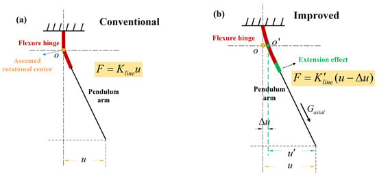
Figure 1.
Comparison before and after analytical model improvement. (a) The conventional analytical model and pendulum deflection schematic; (b) the new analytical model and pendulum deflection schematic.
It should be noted that the bending stiffness of a flexure hinge is determined by the geometrical boundary of a given notch. Equally, the change in the geometrical boundary under the influence of the loads is deduced by bearing an axial tensile force on the hinge. Therefore, “modified bending stiffness” is equal to “modified boundary” plus “bending stiffness”. The general methodology for deriving the improved analytical model is to integrate the modified flexure hinge bending stiffness and the measured displacement error. Based on the force analysis while the pendulum is working in the equilibrium state, the derivation and mathematical equations of the analytical model are given in detail in the following sections.
3. Conventional Analytical Model of the Thrust Stand
In this section, we briefly present the designed thrust stand and use it to give a conventional thrust analytical model.
Like most of the micro-newton thrust balances that are being or have been developed [29,30], we have also developed a thrust stand consisting of a compound pendulum, as shown in Figure 2. Figure 2a shows the 3D structural schema of the thrust stand. In the pendulum, there are two elliptical notched flexure hinges located on both sides of the center axis of the compound pendulum. Each flexure hinge can be thought of as a small-length frictionless pivot, which provides a rotating function and is located in the middle of the hinge. Figure 2b displays a physical diagram of the thrust stand.
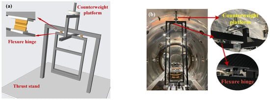
Figure 2.
The designed thrust stand consisting of the compound pendulum (partial). (a) 3D rendering diagram; (b) physical diagram.
Without loss of generality, the pendulum is assumed to operate in an open-loop condition. As a common practice, the micro-newton thrust adopts the quasi-static force measurement method. Figure 3 shows the schematic principle. Table 1 lists the parameters, the corresponding symbols, and the units. Equally, CW denotes the counterweight, while denotes the center of mass of the entire pendulum. The measurement principle is based on the equilibrium of the pendulum torque, given as:
where is the bending stiffness of the flexure hinge. The left side of Equation (1) is the torque provided by the thrust, and the right side of the equation represents the torques associated with the flexure hinge itself and the gravity tangential component, respectively. When the deflection angle is small, for example, less than 5°, it can be considered that [22]. Simplifying Equation (1) yields
where is the torsional stiffness of the pendulum. is the equivalent spring stiffness supplied by the tangential component of gravity , and .
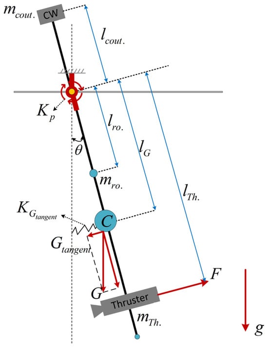
Figure 3.
Schematic diagram of a moment of the compound pendulum swing.

Table 1.
Description of parameters adopted in the model.
Rather than directly measuring the angle , we characterize the magnitude of the thrust by measuring the horizontal displacement of a point on the pendulum arm at a distance from the assumed rotational axis in real applications. Therefore, we have
where is the horizontal displacement of the measurement point. is the linear stiffness of the pendulum, satisfying . From Equation (3), it can be found that all symbols except the bending stiffness of the flexure hinge are characterized by the most refined parameters. The bending stiffness of the hinge, as the key component of the compound pendulum deflection, requires a more explicit parametric equation. Furthermore, if the mass parameter (the subscript “” denotes “”, “”, and “”) will affect the stiffness , or if the non-ideal deformation of the hinge will affect the displacement measurement value , then continuing to use Equation (3) to calculate and analyze will result in deviations. Hence, an improvement needs to be made to the conventional model.
4. The Improved Analytical Model of the Thrust Stand
In the previous section, the thrust measurement principle of the compound pendulum under quasi-static conditions is given in detail. Nevertheless, the effect of gravitational effects on the thrust measurement system for each component of the pendulum is only partially considered—providing the torsional return stiffness of the pendulum. The component of gravity in the normal direction of rotation of the pendulum will exert an axial tensile force on the flexure hinge, which will introduce a shifting of the original . Moreover, an offset in the assumed center of rotation during pendulum deflection can also lead to a false displacement measurement . Therefore, an improved analytical model of the pendulum based on the establishment of a comprehensive theory of flexure hinge bending is presented.
4.1. Hinge Bending Deflection Modeling
The flexure hinge used in the thrust stand is a symmetrical elliptical notched structure, whose physical style is shown in Figure 2, and the structural schematic is given in Figure 4. Based on the Euler–Bernoulli beam theory, it is assumed that the small deflection satisfies the material elastic deformation theory. Moreover, the hinge can only rotate in the XY plane. Here, we define the X-axis as the axial direction of the hinge. The deformations caused by shear and torsion in the other directions are ignored.
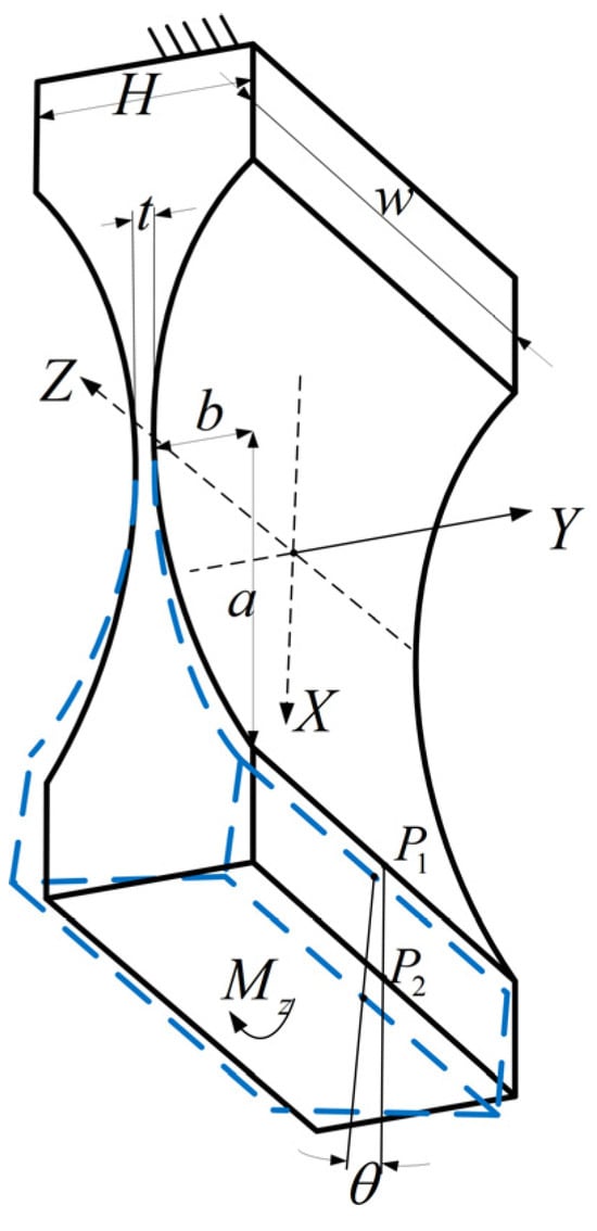
Figure 4.
Bending diagram of a flexure hinge with elliptical notched boundary.
In Figure 4, the blue dashed part indicates the small deflection around the Z-axis (the assumed rotational center) under the bending moment . and are located at the midpoints of the upper and lower sides of the deformed end, respectively. The line connecting the two can be used to indicate the deflection angle . is the width of the hinge and is the height of the hinge. and are the long and short axes of the elliptical notched portion, respectively. is the thickness of the thinnest part in the middle of the hinge, where . The elliptical notched structure represents an intermediate solution between the semicircular structure and the leaf structure. When the long and short axes are equal (), the hinge of the elliptical notch evolves into a semicircular flexure hinge. When approximates to 0, the elliptical notched hinge can be equivalent to a hinge of the leaf structure. Therefore, the analysis of this elliptical notched hinge is of general significance.
There are many methodologies to calculate under the bending moment [31,32,33,34,35]. The commonly used one is to obtain a concise formula for calculating the deflection angle by introducing the elliptic centrifugal angle as an integral variable. The schematic of the bending deflection modeling is shown in Figure 5.
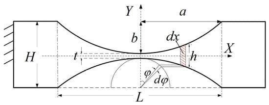
Figure 5.
Schematic diagram of bending deflection modeling based on elliptic centrifugal angle.
In Figure 5, is defined as the centrifugal angle of the ellipse, so an arbitrary point on the ellipse is given [36]:
where has a range of .
It is assumed that the deformation of the hinge is mainly concentrated in the elliptical part where and the deformation of other parts is neglected. The bending of the continuous beam of the variable section is regarded as the result of the accumulation of many tiny bending deformations. Each tiny section is regarded as a rectangular section beam of length (the red shaded part in Figure 5). In general, the size of the hinge is much smaller than that of the pendulum arm, and the bending moment variation can be considered small enough to treat as a constant.
According to the theory of a small deformation of the cantilever beam, we have the following differential equation of the deflection line:
where is the elastic modulus of the material, and is the moment of inertia of the section about the central axis with .
Combining Equations (4) and (5), the hinge deflection angle can be obtained,
where and . The expression of the integral term is obtained using the MATHEMATICA:
In summary, the bending stiffness of the flexure hinge in the direction of thrust measurement can be parametrically modelled as
where the coefficient is
The above parametric modeling successfully establishes the relationship between hinge bending stiffness and its geometric dimensions and refines the characterization of . Its modeling method also provides the basis for other stiffness modeling research to follow.
4.2. Gravity-Induced Extension Effect
As a high-precision compliant mechanism, a flexure hinge often exhibits an increase in length and a decrease in thickness in the axial extension effect under a whole pendulum load (including the counterweight, thruster, and pendulum arm, excluding the hinge itself). These will change the original bending stiffness of the hinge. The bending stiffness shift introduced by the axial extension effect is studied below.
The pendulum, considering the extension effect, is shown in Figure 6. In Figure 6, is the axial component of the gravity of the whole pendulum load, perpendicular to the swing direction. The restoring force generated by the tangential component of gravity has been considered in the conventional analytical model, and it is modeled as an equivalent spring . While the angle is very small, there is . If the load on the hinge is large, the axial extension effect due to is more pronounced, which is manifested as a dimensional change. For this reason, we propose characterizing the gravity-induced extension effect by modeling an additional equivalent spring (see Figure 6). The zero potential energy point of this spring is in the free vertical state of the pendulum.
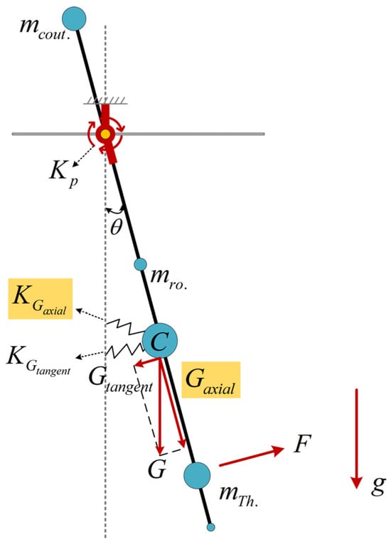
Figure 6.
Schematic diagram of a moment of pendulum swing under extension effect.
The equivalent spring is attached to so that it is shifted and
During the preparation phase of the thrust measurement, the loads are mounted, and the extension effect of the static axial force on the hinge is shown in Figure 7. is the deformation in the axial direction, and the yellow point and the green point are the centers before and after the deformation, respectively. is the thickness after deformation at the center in the middle part, with where is the variation due to the extension effect. In the case of a large cross-sectional aspect ratio, the variation in the hinge width is negligible.

Figure 7.
Schematic diagram of the geometric dimensional changes under axial tension of the flexure hinge.
Applying Castigliano’s second theorem, it follows that
where is the deformation energy, which is given by
where is the cross-sectional area of the hinge, and . Combining Equations (11) and (12) gives
Using the “elliptic centrifugal angle” integration methodology (see Section 4.1 for details), the length elongation is
where satisfies the equation obtained from the MATHEMATICA:
where .
Furthermore, from the theory of Poisson’s ratio () of material, the minimum thickness change in the hinge can be described by
Notably, there exists at tiny deflection angles, so that
Referring to Equations (8) and (9), the improved bending stiffness of the hinge under the tensile pre-stress of the whole pendulum load can be parameterized as
where denotes the value of after the minimum thickness has been reduced by .
It is worthwhile to report that can be represented explicitly, while originates from the additional effect of the hinge’s own geometrical boundary change, which cannot be expressed separately due to the complexity of the calculation.
4.3. Rotational Center Offset Effect
In this section, we proceed to model the offset of the assumed rotational center. An accurate calculation of the thrust based on an analytical model is not only related to the stiffness coefficient (see Equation (3)), but also depends on the reliability of the displacement . That is, the displacement has to be generated by the thrust rather than other unknown factors. However, the hinge is subject to a non-ideal situation during bending deformation—the assumed rotational center would have an offset.
Figure 8a shows that the assumed rotational center will be offset from the position of point (the yellow dot) to the position of (the green dot) during the bending deformation of the hinge. Figure 8b exhibits the uncertainty of the displacement measurement due to the assumed rotational center offset effect . Here, the red part is the bent hinge, the black line is the pendulum arm, is the measured displacement, and is the displacement generated by the actual thrust. Note that the interference of other environmental noises such as seismic vibration and thermal effects on the measurement is not included in this study.
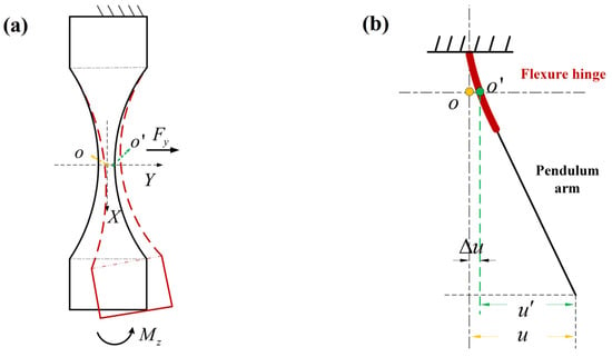
Figure 8.
Flexure hinge bending deformation. (a) Axial section diagram; (b) measurement displacement schematic.
In order to characterize the offset effect at point , a zero-value force is assumed to be applied at point along the Y-axis. According to Castigliano’s second theorem, the following equations exist:
The symbols used in Equation (19) and the subsequent formulas in this section refer to the previous two subsections. Thus, can be derived from the above formula:
The coefficient is expressed as
where . As such, we define the offset line stiffness of the assumed rotational center as
4.4. The Improved and Corrected Analytical Model
In this section, we formulate the improved model of the pendulum considering the extension effect and assumed rotational center offset. During the measurement operation of the thrust stand, the flexure hinge exhibits the characteristics first of elongation and thinning, and then bending. The bending line stiffness () of the pendulum changes accordingly. Moreover, as the hinge bends, the assumed center of rotation is offset, resulting in an error in the displacement measurement ().
Compared to the conventional analytical model represented by Equation (3), the improved analytical model is given as
where is the modified linear stiffness of the pendulum, and . is obtained from the offset stiffness using Equation (22) with . Simplifying the resulting expression yields
Finally, the improved and corrected thrust analytical model is given as
where
Here, the conventional Equation (3) is revised as Equation (25). In particular, the bending stiffness shift in the flexure hinge under an extension effect and the offset of the assumed center of rotation after bending deformation are all taken into account in the new model. In addition, the parametric equations for the bending and tensile deformations of the hinge are derived in detail. Since the elongation and thinning behavior of the hinge occurs before the bending behavior, the initial conditions for the respective modeling are different, so different symbols ( and ) denote the intermediate variables involved.
5. Case Study and Discussion
In this section, case studies and discussions are presented. Firstly, we propose a finite element modeling solution for an elliptical notched hinge. Then, the validity and generalizability of the proposed parametric analytical model are verified using the finite element analysis (FEA) method. Finally, the necessity of the proposed improvements is demonstrated by analyzing the parametric design of multiple sets of thrust stands.
5.1. The Improved and Corrected Analytical Model
The FEA technique is a powerful tool for research in the field of structural mechanics. The well-modeled finite element model (FEM) has very high accuracy in the problem domain of this study. In this research, the FEM results are adopted as a benchmark to verify the validity of the proposed analytical model for thrust analysis. Reasonably, we are interested in the elastic deformation of the flexure hinge. Hence, the bending and tensile deformations of the pendulum arm are neglected by assuming the pendulum arm to be rigid. Moreover, the proposed analytical model points out that the mechanical properties of hinges not previously considered are the core link of the research. Therefore, the focus of finite element modeling is the flexure hinge.
COMSOL Multiphysics 6.0 as a very mature FEA simulation software will be applied. In the FEA, the accuracy of the solution is related to the mesh size. In principle, a finer custom meshing brings higher accuracy. However, it is difficult to be adopted in real applications due to the limitation of time and computing resources. Nevertheless, unstructured meshing algorithms represented by tetrahedral elements are prone to low-quality meshes with distorted tetrahedral shapes when meshing structures with large aspect ratios such as flexure hinges. Consequently, a solution for meshing is given to make the FEM results convincing.
In the finite element modeling, as shown in Figure 9a, the left side of the hinge is the fixed end, and the right side is the free end. A shear force is applied at the middle position of the free end to generate torque with respect to the assumed center of rotation. Based on Saint-Venant’s principle, the length of the non-hinged part is designed to be to avoid the effect of fixed restraint and load on the hinge part with inhomogeneous stress. For the building of the hinge mesh, we divide it into three parts: the fine region A, the transition region B, and the coarse region C, which are described as follows,

Figure 9.
Meshing of the finite element model. (a) Mesh area division; (b) mesh division results.
- (1)
- Region A is the thinnest region of the hinge, has a length about 1/3 of the entire one, and has the characteristics of a large aspect ratio. The stresses and strains in both bending and tensile deformation are large. It is a key concern in force analysis. Therefore, a controlled structured hexahedral mesh is used instead of an unstructured one for the meshing (see Figure 9b). A three-level hexahedral mesh is established in the thickness direction, and 30 and 100 elements are divided in the axial and width directions, respectively, using “mapped” and “swept” techniques to accomplish the above operations. Accordingly, region A is equivalent to a large number of healthy micro-cantilevers.
- (2)
- Region B contains the part of the hinge root with larger curvature, the hexahedral element is no longer applicable, and the physical field-controlled tetrahedral element is used to build the mesh. Furthermore, in order to avoid a poor-quality mesh in the narrow region of the hinge root, a virtual mesh technique is applied to its root to supplement a circular arc-shaped region (see Figure 9a); this region is only used to distinguish the difference between the meshes, and does not have an actual physical partitioning function (i.e., the machining of the hinge shown in Figure 9a is shaped in one piece).
- (3)
- Region C is the part outside the hinge, which is not the focus of attention, so it is subjected to a coarser free-division tetrahedral mesh.
The above meshing scheme for the finite element modeling of the flexure hinge can provide a feasible FEA solution strategy not only for thrust stands but also for flexure hinge structures in other devices.
5.2. Results and Discussion
In this section, we present comparisons between the parametric equations and FEA in order to evaluate the accuracy and generalizability of the proposed parametric equations to describe the mechanical behavior of the hinge. Beryllium copper material is used in the flexure hinge due to its advantages of high mechanical strength and high temperature stability. Table 2 gives the initial geometric parameters and mechanical parameters of the hinge.

Table 2.
Initialization of the flexure hinge parameters.
The primary concern is the reliability of the equations describing the assumed rotational center offset of the hinge in the proposed model. It is noticeable that the length change in the hinge under axial tension can also be interpreted as an axial offset of the assumed rotational center (see Figure 7), except that this offset does not lead to uncertainty in the displacement measurement. The linear stiffness and obtained from the analytical model are and (refer to Equation (14) and Equation (22)), respectively, which are compared with the FEM results to verify the stiffness equations under a small deformation. Figure 10 shows a schematic of the access of FEM results. Five points are selected at equal intervals at the front (fixed end), middle, and rear (free end) of the hinge section, distinguished by black, green, and red in turn (see Figure 10). The mean values of their respective displacements are calculated to represent the displacements at the front, middle, and rear of the hinge. Thus, the bending and tensile deformations caused by the black points are subtracted from the total deformation obtained from the red points or green points to obtain the pure deformation of the flexure hinge itself.
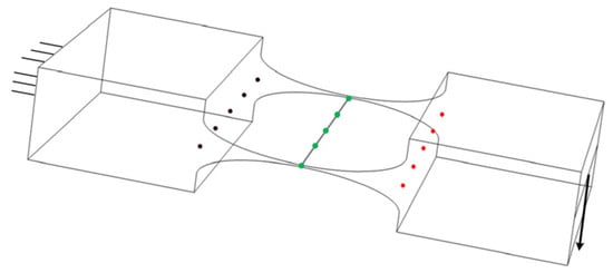
Figure 10.
A schematic of the access of FEM results.
In real applications, the minimum thickness of the flexure hinge frequently becomes the point of penetration for customizing the mechanical properties of the hinge. Therefore, the variation range of the minimum thickness is set to be 0.1~0.4 mm, and the hinge height is kept constant. As formula needs to be satisfied, the short axis matches 1.3~1.45 mm. The other parameters are listed in Table 2. The comparisons within this parameter range are given in Figure 11.
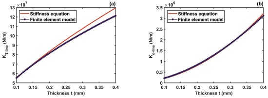
Figure 11.
Comparison of stiffness equation and FEM. (a) Tension line stiffness ; (b) offset line stiffness .
Figure 11a,b present the comparative results of tension line stiffness and offset line stiffness under the stiffness equation and FEM, respectively. It can be obtained that the result curves calculated by the stiffness equations agree well with the result curves of FEM, and they also have the same trend of change. In addition, the hinge tension line stiffness is much greater than the offset line stiffness by about two orders of magnitude over a range of variations in parameter . This is because the function of the hinge is to provide bending rather than axial elongation. The comparative results seen for an incomplete fit mainly come from the assumptions made in those theoretical derivations. It can be substantiated that the equations (Equations (14) and (22)) describing the hinge rotational center offset in the proposed analytical model are valid when the thickness is within the allowed variation range.
The accuracy of the hinge bending stiffness equation is central to the persuasiveness of the proposed model. With reference to (see Equation (8)), we define the bending line stiffness of the hinge as . It is important to point out that the actual displacement produced by the force in the FEM should be the displacement of the free end of the hinge minus the offset of the middle of the hinge due to the offset of the assumed rotational center. The comparison is plotted in Figure 12. The results of the equation calculation and the FEM results also have small discrepancies and the same trends, which verifies the stiffness equation (Equation (8)). Comparing Figure 11b, the offset line stiffness is only about 10 times higher than the bending line stiffness for the hinge itself. Even if the thrust is applied at the end of the pendulum arm rather than at the end of the hinge in practice, this multiplier is magnified again. However, the system still has significant measurement uncertainty due to the offset of the assumed rotational center. The subsequent analysis will give a detailed confirmation of this point.
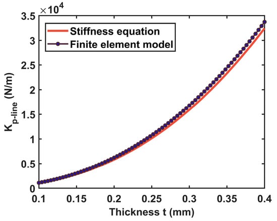
Figure 12.
Comparison of stiffness equation for bending line stiffness with FEM.
In order to further investigate the influence of dimensional changes on the bending stiffness under a gravity-induced extension effect in the hinge proposed in the analytical model (refer to Equation (18)), an axial tensile force is first applied to the hinge in the FEM. Then, the changing dimensional parameters are recorded and modified before applying force , which provides torque. It is significant to emphasize that the axial tensile force needs to be removed after the correction of the hinge dimensional parameters; otherwise, an additional stiffening effect will be introduced. Meanwhile, the offset of the assumed rotational center is also considered in the FEA. Based on the thrust stand we designed, the whole pendulum load needs to reach about 10 kg. Thus, we choose . The results of the bending line stiffness variation obtained using both approaches are shown in Figure 13. Such results show that the overall effect of the dimensional change is a decrease in the bending line stiffness. It can be observed that the stiffness equation successfully predicts the variation in the bending line stiffness under the axial tensile force, and it coincides very well with the FEM fitting (the green curve in Figure 13). Among them, the best prediction is achieved when the thickness lies in the range of 0.1 mm to 0.2 mm.
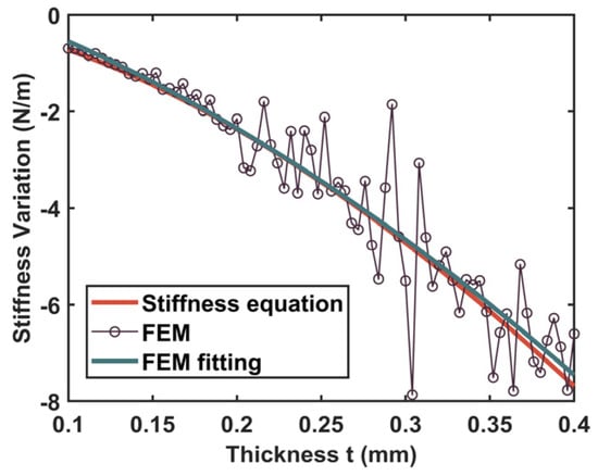
Figure 13.
Bending line stiffness variation of the flexure hinge under gravity-induced extension effect.
In addition, combined with Equation (10), it can be seen that the variation in stiffness is equivalent to in the formula, and the difference between the two is a conversion multiple of linear stiffness and torsional stiffness. In other words, the presented analytical model can accurately give the numerical solution of the bending stiffness shift in the flexure hinge under a certain pendulum load, indicating that it makes sense.
To demonstrate the generalizability of the improved analytical model for different notch boundary sizes and dimensions of the hinge, two additional sets of studies (see Table 3) are carried out as follows. Figure 14 shows the comparisons for Case I. It is clear from Figure 14a–c those stiffness parametric equations give a precise description of the corresponding stiffness even under the condition of a wide range of variation in the elliptic long axis parameter a. Since there are several outlier points in the FEM result, the first fitting (the green curve) is not convincing, as shown in Figure 14d. The fitting result of the post-processing FEM (the yellow curve) is highly consistent with that of the stiffness equation. The comparisons under Case II are plotted in Figure 15. The results demonstrate the predictive performance of these parametric equations. Notably, the bending line stiffness variation under an axial extension effect is independent of the hinge width.

Table 3.
Two additional sets of the flexure hinge geometric parameters traversed.
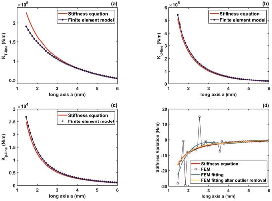
Figure 14.
Comparisons of the stiffness equations and FEM under Case I. (a) Tension line stiffness ; (b) offset line stiffness ; (c) bending line stiffness ; (d) bending line stiffness variation under axial tensile force.
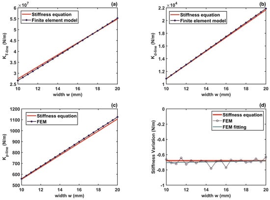
Figure 15.
Comparisons of the stiffness equations and FEM under Case II. (a) Tension line stiffness , (b) offset line stiffness , (c) bending line stiffness , (d) bending line stiffness variation under axial tensile force.
Furthermore, Figure 16 demonstrates the comparisons under three typical flexure hinges. The three hinges maintain a consistent minimum thickness of , and their key boundary parameters are provided by the table in the figure. The results again verify the improved analytical model. In the meantime, it can be summarized that the elliptical notched hinge has both the advantage of the circular notched hinge, which has a clear center of rotation, and the advantage of the leaf-type hinge, which has less bending line stiffness. This is because with a very large bending line stiffness, the displacement from a micro-thrust may be not perceptible.
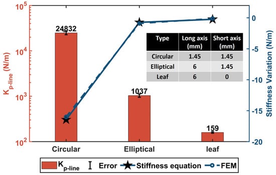
Figure 16.
A bending line stiffness comparison of three typical structures of flexure hinges.
In summary, these case studies on the flexure hinge reflect, on the one hand, the validity and generalizability of the proposed new quasi-static thrust analytical model. On the other hand, the variation laws of those stiffness properties of the hinge with the changes in its geometrical parameters are shown in those comparative analyses. Therefore, based on the parametric equation of the bending stiffness, the appropriate can be easily found for the thrust stand with the selection of its independent variables. In the next section, we demonstrate the necessity of improvements to the conventional model analytically.
5.3. Discussion for Thrust Measurement
In the previous sections, we verified the accuracy of the improved analytical model in characterizing the neglected parts in conventional thrust analytical models, including the shift in the bending stiffness and the offset of the assumed rotational center during the actual operation. In this section, we illustrate that the presence of these non-ideal factors can introduce large uncertainties into the theoretical analysis of thrust measurements, which is worthy of attention by designers of thrust stands.
On the basis of what is studied in Figure 12 and Figure 13 (the parameter changes with (, and remains constant), attention is paid to the impact of the change in the hinge bending stiffness on the thrust analysis. We rewrite Equation (24) as follows:
where is the revised thrust calculated by the improved analytical model. And
Figure 12 and Figure 13 show that the equivalent spring stiffness introduced by the gravitational force component is a negative number and its magnitude is small with respect to the original stiffness (about 0.02% to 0.06% of the total). Thus, if the pendulum is designed so that the pendulum load gravity component provides the main torsional return stiffness, then the effect of the shift in will be very slight. On the other hand, a problem with this is that the heavy load requirements of the pendulum often make the equivalent stiffness too large, making displacement measurements much more difficult. Therefore, the designer will adjust the counterweight to make as small as possible, or even have a negative equivalent stiffness to weaken the stiffness effect of , so as to obtain a lower total stiffness coefficient . This is exactly what our team is trying to undertake. In such a case, the effect of the shift in on the thrust will be magnified, and needs to be seriously considered.
To quantify the above analyses, several case studies are carried out, with the parameters for the compound pendulum given in Table 4. The six designs are divided into three groups: A, B, and C. The minimum thickness of the hinge is in both groups A and B, while is 0.3 mm in group C. The other geometric parameters of the hinge are provided in Table 2. The difference between groups A and B lies in the different thrusters and counterweight masses; the total stiffness coefficient is adjusted by changing the height of the counterweight bar within each group. The position of the thruster is fixed in different groups, and the length and mass of the pendulum arm vary with the height of the counterweight bar. The acceleration of gravity is chosen as . The distance from the measurement point to the assumed rotational center is , and the true value of the displacement at the measurement point is assumed to be . The results of the stiffness and thrust obtained with these three groups of parameters are reported in Table 5, where is the absolute error of thrust and is the relative error.

Table 4.
Designs of the compound pendulum parameters.

Table 5.
Calculation results of stiffness and thrust under different parameter designs.
From these results, it can be observed that the original bending stiffness is determined by its own dimensions (here ). In addition, the shift () in is determined by both the pendulum load gravity and the hinge dimensions. A negative value of the equivalent stiffness may cancel most of the hinge’s own stiffness , making the effect of the stiffness shift () amplified, leading to large uncertainties in the thrust calculations, such as 1.57% in A1, 0.29% in B1, and 7.84% in C1. However, the high-precision metrology standard generally needs to reach an error level of 0.05% or even higher, and only the designs in A2, B2, and C2 can reach this error level.
Table 6 shows the effect of the offset of the assumed rotational center on the theoretical calculation of thrust under several sets of different parameters. The geometric parameters of the hinge, except for the minimum thickness , are shown in Table 2, and the structural parameters of the compound pendulum are shown in group A2 in Table 4. Again, and are set. The thrust calculation error due to the bending stiffness shift is not considered at this point. From the relative error results (see Table 6), it can be obtained that the offset of the assumed rotational center introduces non-negligible uncertainty into the thrust calculation. And this relative error depends mainly on the geometric parameters of the hinge, independent of the measured displacement.

Table 6.
Calculation results of thrust in case of offset of the assumed rotational center.
To sum up, it is necessary to always pay attention to the influence of when the designer of the compound pendulum tries to customize the stiffness coefficient by changing the weight or height of the counterweight. The shift () of the hinge bending stiffness can be regarded as the systematic error of the thrust measurement device together with the offset of the assumed rotational center. The systematic error of the equipment needs to be taken seriously in the design or measurement process. Ultimately, an improved analytical model that takes these factors into account is given in Equation (25).
6. Conclusions
This study investigated a new analytical model of thrust measurement for a thrust stand with a flexure hinge structure, in an attempt to compensate for the uncertainty that is not considered in conventional thrust analytical models. It is pointed out that the uncertainty comes from two neglected aspects: first, the pendulum load during calibration and the measurement of thrust will produce an axial extension effect on the flexure hinge, which will change the stiffness coefficient that has been considered a constant; second, the assumed center of rotation will be offset when the pendulum is deflected by the thrust, which will introduce the displacement measurement error. Hinge models under different parameter designs are analyzed using finite element methods and theoretical models, and the results prove the validity and generalizability of the proposed analytical model.
The significance of this work is to point out the systematic errors that exist in the thrust stand itself, which should be paid attention to as high-precision metrology equipment. The improved model will guide the design of the structural parameters of the thrust stand composed of the compound pendulum, so that it can minimize the uncertainty introduced by the variation of the system’s own characteristics.
Meanwhile, it is worth emphasizing that the accuracy of the parametric modeling of the flexure hinge is the basis for maintaining consistency between theory and practice. Compared to other stiffness modeling methods for elliptical notched flexure hinges such as inverse conformal mapping and empirical equations from FEA, etc., the modeling method based on the Euler beam linear integral and Castigliano’s second theorem used in this study is more applicable and available. Within a wide range of hinge geometric parameters, the proposed stiffness equation achieves results that are consistent with simulation practices. Additionally, further improvements to the hinge stiffness equation will enhance our work.
Author Contributions
Conceptualization, X.C. and Z.L.; methodology, X.C. and Z.L.; software, X.C.; investigation, X.C.; resources, L.Z.; data curation, L.Z. and J.X.; writing—original draft preparation, X.C.; supervision, J.X.; project administration, L.Z.; funding acquisition, L.Z. All authors have read and agreed to the published version of the manuscript.
Funding
This work is supported by the National Key R&D Program of China (Grant No. 2021YFC2202703), the Postgraduate Research and Practice Innovation Program of Jiangsu Province (Grant No. KYCX23_0231), and the National Natural Science Foundation of China (Grant Nos. 51905094 and 52275093).
Data Availability Statement
Data will be made available on request.
Acknowledgments
We would like to thank the above funders for their technical and financial support.
Conflicts of Interest
The authors declare no conflict of interest.
References
- Li, H.; Wu, Z.; Sun, G. A model for macro-performances applied to low power coaxial pulsed plasma thrusters. Acta Astronaut. 2020, 170, 154–162. [Google Scholar] [CrossRef]
- Xia, Q.; Wang, N.; Wu, X. The influence of external magnetic field on the plume of vacuum arc thruster. Acta Astronaut. 2019, 164, 69–76. [Google Scholar] [CrossRef]
- Anderson, G.; Anderson, J.; Anderson, M. Experimental results from the ST7 mission on LISA Pathfinder. Phys. Rev. D 2018, 98, 102005. [Google Scholar] [CrossRef]
- Armano, M.; Audley, H.; Auger, G. The LISA pathfinder mission. In Journal of Physics: Conference Series, Proceedings of the 10th International LISA Symposium, Gainesville, FL, USA, 18–23 May 2014; IOP Publishing: Bristol, UK, 2015; Volume 610, p. 610. [Google Scholar] [CrossRef]
- Armano, M.; Audley, H.; Baird, J. LISA Pathfinder platform stability and drag-free performance. Phys. Rev. D 2019, 99, 082001. [Google Scholar] [CrossRef]
- Tajmar, M. Overview of indium LMIS for the NASA-MMS mission and its suitability for an In-FEEP thruster on LISA. In Proceeding of the International Electric Propulsion Conference, IEPC-2011, Wiesbaden, Germany, 11–15 September 2011. [Google Scholar]
- Danzmann, K.; Prince, T.A.; Binetruy, P. LISA: Unveiling a hidden Universe. Assess. Study Rep. ESA/SRE 2011, 3. [Google Scholar] [CrossRef]
- Anselmo, M.R.; Marques, R.I. Torsional thrust balance for electric propulsion application with electrostatic calibration device. Meas. Sci. Technol. 2019, 30, 055903. [Google Scholar] [CrossRef]
- Lun, J.; Law, C. Direct thrust measurement stand with improved operation and force calibration technique for performance testing of pulsed micro-thrusters. Meas. Sci. Technol. 2014, 25, 095009. [Google Scholar] [CrossRef]
- Frollani, D.; Coletti, M.; Gabriel, S.B. A thrust balance for low power hollow cathode thrusters. Meas. Sci. Technol. 2014, 25, 065902. [Google Scholar] [CrossRef]
- Orieux, S.; Rossi, C.; Esteve, D. Thrust stand for ground tests of solid propellant microthrusters. Rev. Sci. Instrum. 2002, 73, 2694–2698. [Google Scholar] [CrossRef]
- Grubišić, A.N.; Gabriel, S.B. Development of an indirect counterbalanced pendulum optical-lever thrust balance for micro-to millinewton thrust measurement. Meas. Sci. Technol. 2010, 21, 105101. [Google Scholar] [CrossRef]
- Acosta-Zamora, A.; Flores, J.R.; Choudhuri, A. Torsional thrust balance measurement system development for testing reaction control thrusters. Measurement 2013, 46, 3414–3428. [Google Scholar] [CrossRef]
- Lam, J.K.; Koay, S.C.; Lim, C.H. A voice coil based electromagnetic system for calibration of a sub-micronewton torsional thrust stand. Measurement 2019, 131, 597–604. [Google Scholar] [CrossRef]
- Xu, K.G.; Walker, M.L.R. High-power, null-type, inverted pendulum thrust stand. Rev. Sci. Instrum. 2009, 80, 055103. [Google Scholar] [CrossRef] [PubMed]
- Knoll, A.; Lamprou, D.; Lappas, V. Thrust balance characterization of a 200 W quad confinement thruster for high thrust regimes. IEEE Trans. Plasma Sci. 2014, 43, 185–189. [Google Scholar] [CrossRef]
- Hey, F.G.; Keller, A.; Braxmaier, C. Development of a highly precise micronewton thrust balance. IEEE Trans. Plasma Sci. 2014, 43, 234–239. [Google Scholar] [CrossRef]
- Zhang, H.; Duan, B.; Wu, L. Development of a steady-state microthrust measurement stand for microspacecrafts. Measurement 2021, 178, 109357. [Google Scholar] [CrossRef]
- Trezzolani, F.; Magarotto, M.; Manente, M. Development of a counterbalanced pendulum thrust stand for electric propulsion. Measurement 2018, 122, 494–501. [Google Scholar] [CrossRef]
- Wachs, B.N.; Jorns, B.A. Sub-millinewton thrust stand and wireless power coupler for microwave-powered small satellite thrusters. Rev. Sci. Instrum. 2022, 93, 083507. [Google Scholar] [CrossRef]
- Wang, A.; Wu, H.; Tang, H. Development and testing of a new thrust stand for micro-thrust measurement in vacuum conditions. Vacuum 2013, 91, 35–40. [Google Scholar] [CrossRef]
- Polk, J.E.; Pancotti, A.; Haag, T. Recommended practice for thrust measurement in electric propulsion testing. J. Propul. Power 2017, 33, 539–555. [Google Scholar] [CrossRef]
- Wei, H.; Tian, Y.; Zhao, Y. Two-axis flexure hinges with variable elliptical transverse cross-sections. Mech. Mach. Theory 2023, 181, 105183. [Google Scholar] [CrossRef]
- Xu, N.; Dai, M.; Zhou, X. Analysis and design of symmetric notch flexure hinges. Adv. Mech. Eng. 2017, 9, 1687814017734513. [Google Scholar] [CrossRef]
- Ma, W.; Wang, R.; Zhou, X. The performance comparison of typical notched flexure hinges. Proc. Inst. Mech. Eng. Part C J. Mech. Eng. 2020, 234, 1859–1867. [Google Scholar] [CrossRef]
- Liu, M.; Zhang, X.; Fatikow, S. Design and analysis of a multi-notched flexure hinge for compliant mechanisms. Precis. Eng. 2017, 48, 292–304. [Google Scholar] [CrossRef]
- Cesare, S.; Musso, F.; D’Angelo, F. Nanobalance: The European balance for micro-propulsion. In Proceedings of the 31st International Electric Propulsion Conference, Ann Arbor, MI, USA, 20–24 September 2009; p. 2009-0182. [Google Scholar]
- Xu, H.; Gao, Y.; Mao, Q.B. A compound pendulum for thrust measurement of micro-Newton thruster. Rev. Sci. Instrum. 2022, 93, 064501. [Google Scholar] [CrossRef]
- Rocca, S.; Menon, C.; Nicolini, D. FEEP micro-thrust balance characterization and testing. Meas. Sci. Technol. 2006, 17, 711. [Google Scholar] [CrossRef]
- Luna, J.P.; Edwards, C.H.; Del Amo, J.G. Development status of the ESA micro-Newton thrust balance. In Proceedings of the 32nd International Electric Propulsion Conference, Wiesbaden, Germany, 11–15 September 2011. [Google Scholar]
- Paros, J.M. How to design flexure hinges. Mach. Des. 1965, 37, 151–156. [Google Scholar]
- Liu, M.; Zhang, X.; Fatikow, S. Design and analysis of a high-accuracy flexure hinge. Rev. Sci. Instrum. 2016, 87, 055106. [Google Scholar] [CrossRef]
- Linß, S.; Gräser, P.; Räder, T. Influence of geometric scaling on the elasto-kinematic properties of flexure hinges and compliant mechanisms. Mech. Mach. Theory 2018, 125, 220–239. [Google Scholar] [CrossRef]
- Zhu, Z.W.; Zhou, X.Q.; Wang, R.Q. A simple compliance modeling method for flexure hinges. Sci. China Technol. Sci. 2015, 58, 56–63. [Google Scholar] [CrossRef]
- Li, T.M.; Zhang, J.L.; Jiang, Y. Derivation of empirical compliance equations for circular flexure hinge considering the effect of stress concentration. Int. J. Precis. 2015, 16, 1735–1743. [Google Scholar] [CrossRef]
- Chen, G.; Liu, X.; Du, Y. Elliptical-arc-fillet flexure hinges: Toward a generalized model for commonly used flexure hinges. J. Mech. Des. 2011, 133, 081002. [Google Scholar] [CrossRef]
Disclaimer/Publisher’s Note: The statements, opinions and data contained in all publications are solely those of the individual author(s) and contributor(s) and not of MDPI and/or the editor(s). MDPI and/or the editor(s) disclaim responsibility for any injury to people or property resulting from any ideas, methods, instructions or products referred to in the content. |
© 2024 by the authors. Licensee MDPI, Basel, Switzerland. This article is an open access article distributed under the terms and conditions of the Creative Commons Attribution (CC BY) license (https://creativecommons.org/licenses/by/4.0/).