Abstract
A common consensus is that an optimized curve profile of the stroke ring in the multiple-stroke piston motor can make the output torque more stable. However, the ring generates elastic deformation during operation, which causes the piston component movement trajectory to deviate from the ideal design curve. To address this issue, first, a liquid–solid coupling simulation model was established to obtain the deformation of the ring, and the accuracy of the model was verified through experiments. Second, a stroke ring curve design method based on elastic deformation pre-compensation was proposed. Through this method, a compensated curve can be obtained to make the actual working curve more in line with the ideal curve. Finally, the dynamic characteristics of three different types of multiple-stroke piston motor curves were analyzed—the ideal design curve, the uncompensated working curve, and the compensated working curve. The results showed that the motor torque pulsation rates are 0.821%, 4.723%, and 0.986%, respectively, and the compensated working curve has a relatively reduced pulsation rate of 79.12% compared to the uncompensated working curve, which verifies that this design method can effectively improve motor performance.
1. Introduction
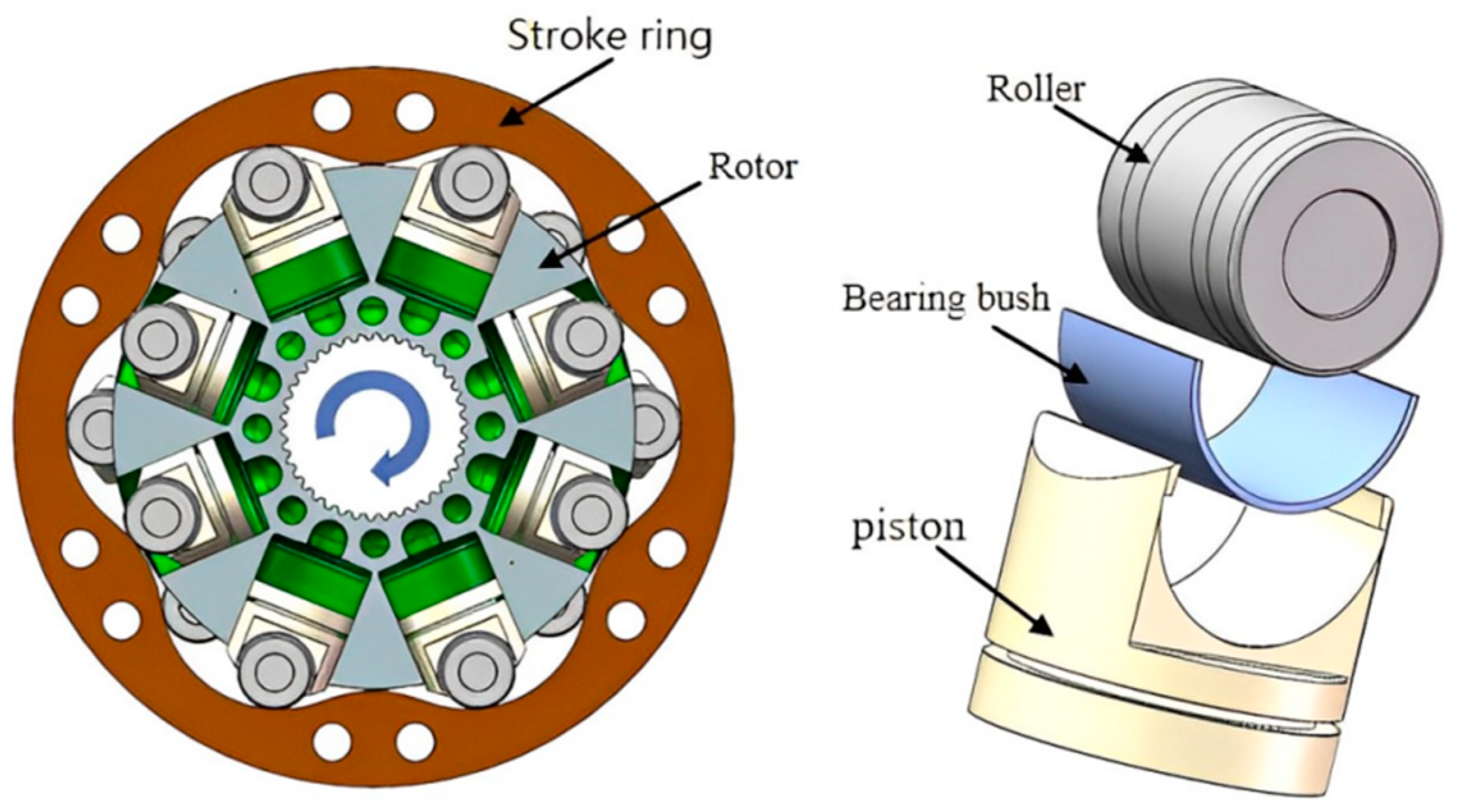
Hydraulic drive plays an important role in modern industry [1,2,3]. The multiple-stroke piston motor has the characteristic of high output torque at low speed and is widely used in military, engineering machinery, shipbuilding, and other industries [4,5,6]. Its typical structure is shown in Figure 1. When the bottom of the piston is forced by high-pressure oil, the roller is pressed on the inner surface of the stroke ring, and a reaction force is provided by the stroke ring. The tangential component of the force rotates the rotor, and the hydraulic energy converts to mechanical energy. During the movement process, the stroke ring, as a core component of the multiple-stroke piston motor [7,8], determines the motion characteristics of the piston assembly and affects the output characteristics of the motor. Therefore, many scholars have conducted research on optimizing the ring curve.
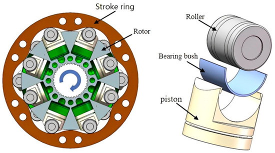
Figure 1.
Typical structure of multiple-stroke piston motor.
Recently, Dasgupta et al. [9] analyzed the output stability of the multiple-stroke piston motor, which showed that the motor had good output characteristics at low speed and high torque. In order to further optimize the curve, Yu et al. [10] carried out theoretical research on its optimization design and accuracy. An improved heart-shaped contour stroke ring curve was proposed to reduce its impact pulsation, and the influence of the equivalent piston number, calculated using piston numbers and cycle numbers on the pulsation rate of the motor, was obtained. Liu et al. [11] studied the impact of different full flow coefficients on the pressure of piston chamber and output torque of the motor. When the full flow coefficient is 0.3, the output torque of the motor has better stability. Zhang et al. [12] studied inertial force and friction force on the stroke ring and proposed an optimization design method based on a genetic algorithm to design a special stroke ring with a high-order function curve. The result indicated that the motor pulsation rate is lower than the original curve. Nguyen et al. [13] proposed a general method for designing cam mechanisms using nonuniform rational B-spline curves (NURBS). The results show that the NURBS curve is superior to the polynomial one in terms of vibration and inertial force and can achieve any movement of the cam mechanism. Xin [14] proposed a new generalized elliptical stroke ring curve, and the effects of various factors on its output torque pulsation were studied to obtain a stroke ring curve with a lower pulsation rate. Related scholars have made great progress in studying the stroke ring curve to reduce the output torque pulsation rate. But actually, the output results deviate from the ideal results, because the high-pressure deformation [15,16,17] on the stroke ring surface causes the contact line between the piston assembly and the ring to deviate from the ideal curve.
At present, there is relatively little research on the elastic deformation compensation for the multiple-stroke piston motor, but in other fields with high precision requirements, the use of deformation compensation design has already achieved an improvement in mechanical performance. For example, Li et al. [18] proposed a deformation error compensation strategy for cutting tools to solve the problem of reduced machining accuracy caused by the deformation of cutting tools during the machining process. Huang et al. [19] developed a new elastic deformation compensation interpolation algorithm, and experimental simulation results showed that this algorithm solved the problem of low tracking accuracy caused by elastic deformation in the feed drive system. Wang et al. [20] proposed a deformation compensation method based on higher-order convergence to solve the machining errors caused by deformation in the end-milling process of large thin-walled parts and verified the effectiveness of the method through experiments. In addition, other factors can also have an impact on torque pulsation, such as the elastic modulus of the oil [21]. But this study focuses on curve pre-compensation for stroke ring deformation to optimize the output stability of hydraulic motors.
In this study, firstly, the force analysis of the stroke ring is carried out, and the hydraulic simulation model of the motor is developed to obtain the hydraulic pressure at the bottom of the piston. Secondly, the motor transient dynamic model established with CAE is co-simulated with the hydraulic simulation to complete the liquid–solid coupling simulation, and the correctness of the model is verified through testing. Finally, an iterative optimization design method is proposed to obtain the compensated curve, which makes the contact point trajectory of the stroke ring and piston approach the ideal curve during the working process. Through the liquid–solid coupling simulation, the output torques of three motors with different types of curves are analyzed to verify the effectiveness of the design method—the ideal design curve, the uncompensated working curve, and the compensated working curve.
2. Simulation Model
2.1. Force Analysis
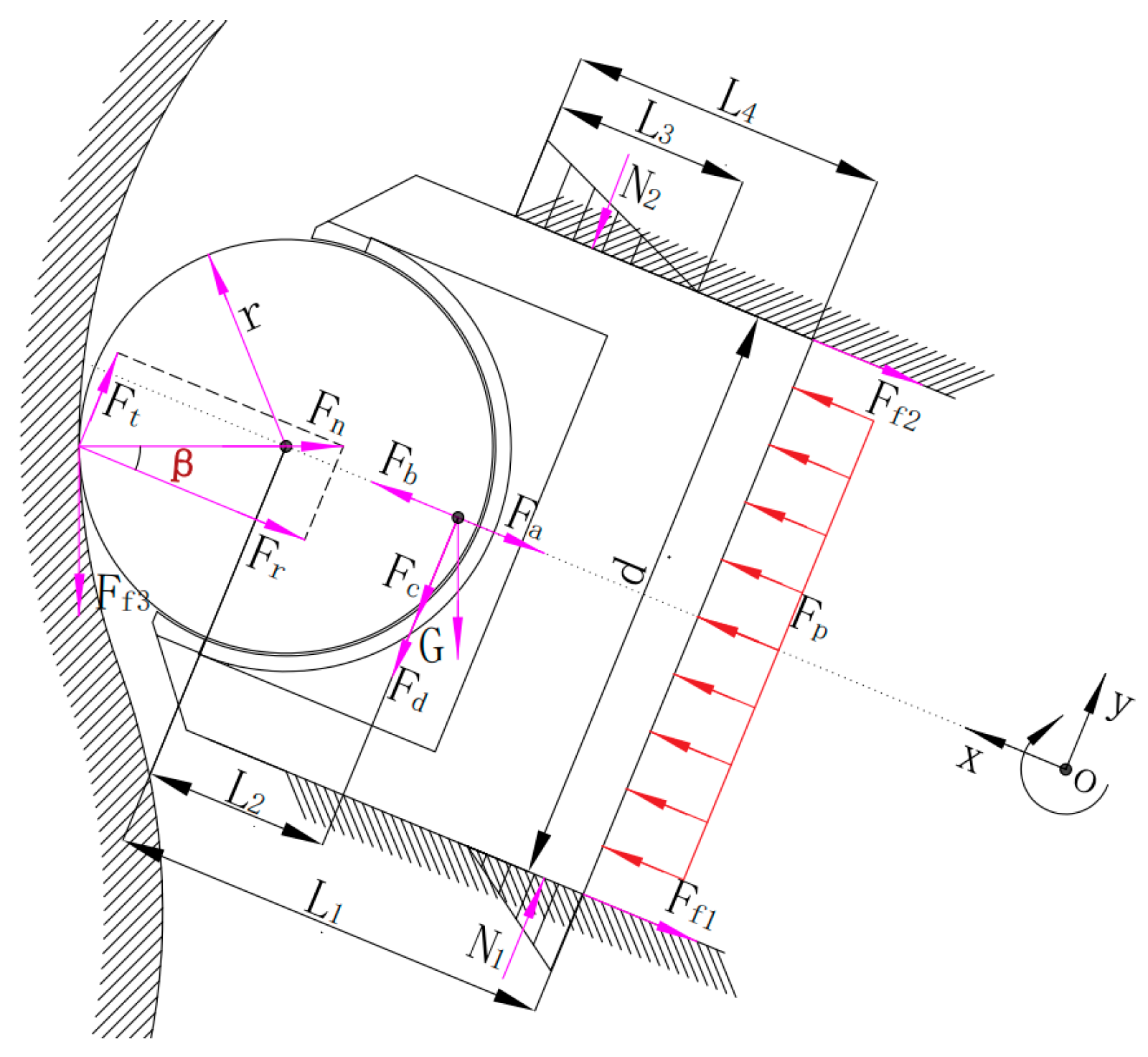
In order to analyze the factors that affect the deformation of the stroke ring, it is necessary to understand the force exerted by the rollers on the stroke ring. Figure 2 is a schematic diagram of the force analysis of piston assembly and stroke ring. The piston assembly is driven by high-pressure oil, which presses the piston assembly against the stroke ring, causing the stroke ring to exert a reaction force on the piston assembly. The tangential component of the reaction force drives the rotor to rotate.
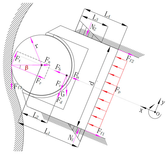
Figure 2.
Piston assembly force diagram.
The hydraulic pressure produced by the piston chamber pressure oil is:
where d is the piston diameter and p is the piston chamber pressure.
The inertial force of the piston assembly relative to the rotor motion is:
where is the mass of the piston assembly, is the angular velocity of the motor rotor, is the polar diameter from the pole center of the stroke ring to the center of the roller, and is the rotation angle of the rotor.
The centrifugal force of the piston assembly relative to the rotor motion is:
where is the polar radius from the pole center of stroke ring to the mass center of piston assembly.
The inertial force caused by the angular acceleration of the motor can be obtained from:
where is the angular acceleration of the motor.
The motion of the piston assembly is bulk motion, and the Gauche inertial force generated by Cauche acceleration is expressed as:
The friction force generated by the relative motion of the roller and the stroke ring is:
where is the rolling friction coefficient between the two, and is the reaction force of the ring to the roller.
The reaction force can be decomposed into tangential force and radial force and the expressions are given by:
where is pressure angle.
The friction force between the piston and the rotor determined by the force and is:
where is friction coefficient between the piston and the rotor, is the action range of , which can be expressed as . is the contact length of the piston in the rotor piston chamber.
According to the balance of force and moment, the reaction force can be calculated as follows [12]:
where K can be expressed as .
In addition, the piston assembly is also affected by its own gravity G, the inertial force of the pressure oil in the piston chamber, and the viscous friction force of the oil, but these forces are generally small and negligible.
According to the Hertzian contact theory [22], the contact between the roller and the stroke ring can be simplified as parallel contact between two cylinders, and the total deformation of the stroke ring can be calculated as follows:
where is the contact length. is the equivalent Young’s modulus, which can be expressed as . , and , , respectively, are Poisson’s ratio and elastic modulus of roller and stroke ring. is the equivalent curvature radius, which can be expressed as . R is the radius of the roller and is the curvature radius of stroke ring (the plus sign in the formula indicates external contact).
This study focuses on a low-speed and high-torque hydraulic motor. And due to the little inertial force and centrifugal force of the piston assembly generated by small speed, the hydraulic pressure at the bottom of the piston (related to the load size) and the pressure angle become the principal factors affecting the force of the stroke ring.
2.2. Transient Dynamic Model
In order to simulate the deformation of the stroke ring in actual work, it is necessary to build a transient dynamic simulation model in ANSYS/Workbench [23,24,25]. The steps are as follows:
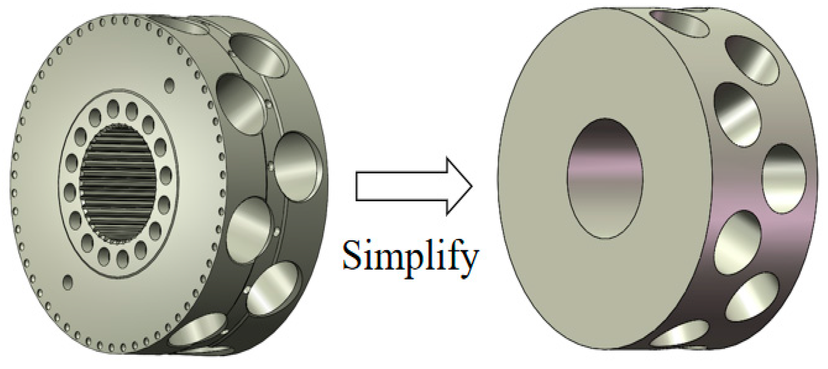
Step 1: Simplify the 3D model. Chamfers, rounded corners, hole slots, etc., were removed. The comparison before and after simplification is shown in Figure 3. Its purpose is to avoid stress singularity and improve work efficiency. Meanwhile, the focus of this study is on the deformation of the stroke ring, and the impact of removed chamfers and other features on the research content can be ignored.
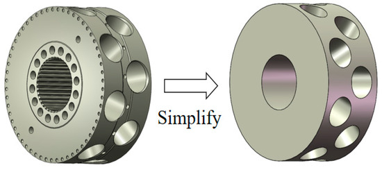
Figure 3.
Process of simplification of the rotor.
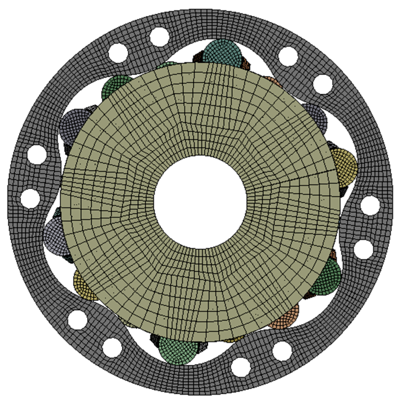
Step 2: Import the simplified 3D model into HyperMesh for hexahedral mesh generation, as shown in Figure 4. Compared to tetrahedral meshes, hexahedral meshes have fewer quantities, faster calculations, and higher accuracy. Therefore, the generated mesh model is imported into the dynamic simulation.
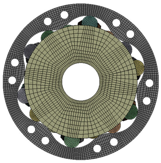
Figure 4.
Mesh of multiple-stroke piston motor.
Step 3: Select the External Model module in ANSYS/Workbench to import the inp format file, and then connect it with the Transient Structural module to import the mesh model and use it for solving.
Step 4: Define material properties for different parts of the model, as shown in Table 1.

Table 1.
Material properties.
Step 5: Add constraints, as shown in Table 2.
Table 2.
Constraints.
Step 6: In the contact setting between the stroke ring and the roller, select a friction contact with a friction coefficient of 0.1, use the Augmented Lagrangian contact algorithm, and set the normal stiffness coefficient to 1.5.
Step 7: Apply pressure to each piston in the direction perpendicular to the bottom of the piston and apply rotational speed to the rotor (both pressure and rotational speed can be obtained through an AMESim simulation model).
Step 8: In the solver settings, select the implicit solver for transient solving.
Step 9: Perform mesh independence verification. Considering the simulation efficiency and periodic characteristics of the motor piston, a single-piston model was used to obtain a reasonable number of grids. The maximum deformation of the stroke ring was used as a characterization parameter to simulate, and the mesh refinement process is mainly aimed at the rollers and the stoke ring. The simulation results are shown in Figure 5; when the number of meshes exceeds 35,000, the maximum deformation of the stroke ring begins to fluctuate steadily, with a fluctuation error of less than 4.66%. Taking into account simulation quality and efficiency, a mesh partitioning method of approximately 41,000 meshes was used as an example to partition the multi piston model. The final mesh division result consists of 353,310 meshes, with an average grid quality of 0.8127.
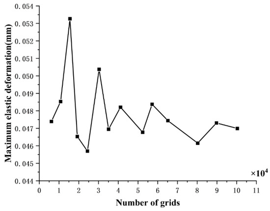
Figure 5.
Mesh independence verification.
2.3. Hydraulic Model
In order to simulate the elastic deformation of the stroke ring and its impact on the output characteristics of the motor, a hydraulic model of the motor was established to obtain the piston chamber pressure and the dynamic performance of the motor.
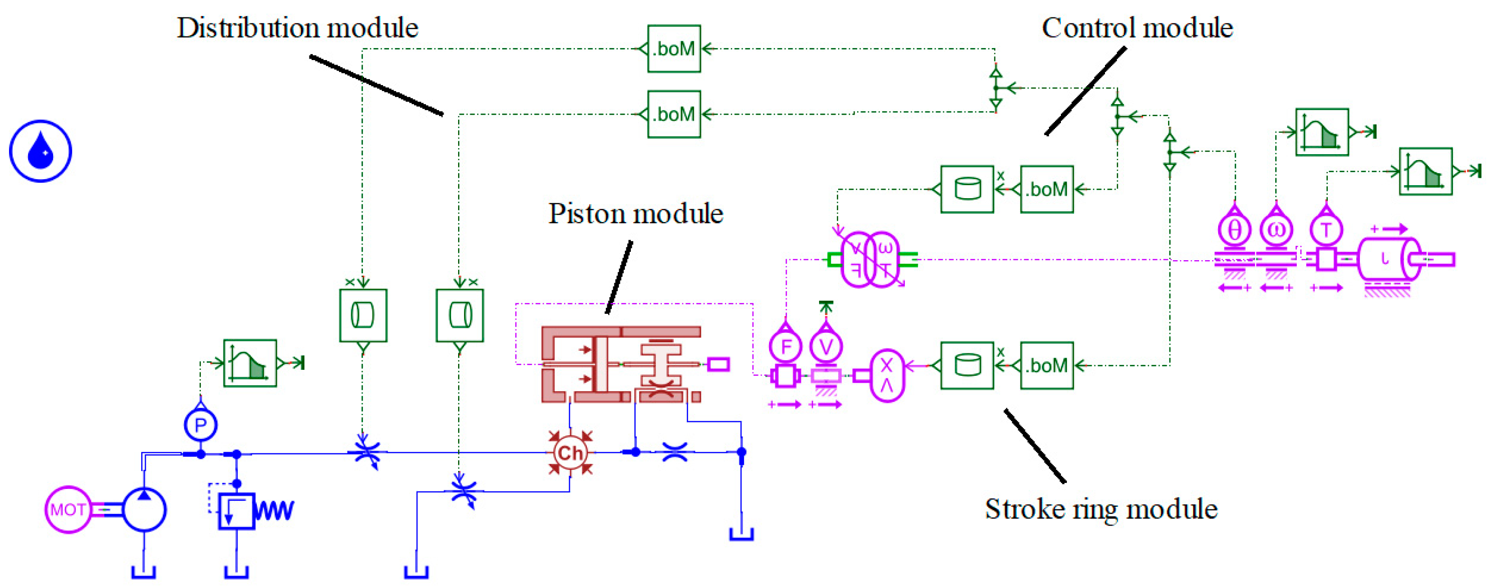
Through the motor structure parameters, a single-piston hydraulic model was established in AMESim [26], as shown in Figure 6. The model consists of a distribution module, a piston module, a stroke ring module, and a control module. The distribution module simulates the fluid distribution process of the valve plate by controlling the opening area of the throttle valve to realize the change of the flow area of the valve plate. The piston module simulates the trajectory of the motor piston, the volume change of the piston chamber, the leakage between the piston and the roller, and the leakage between the piston and the rotor piston chamber. The stroke ring module describes the stroke ring profile by inputting the curve function, so that the movement of the piston can be limited. The control module feedback the rotation angle of the motor through the angle sensor to control the opening area of the throttle valve and the motion characteristics of the piston and form a feedback loop. Finally, the torque output of the motor is obtained by multiplying the force acting on the piston by the degree velocity of the piston through the rotary–linear modulated transformer.
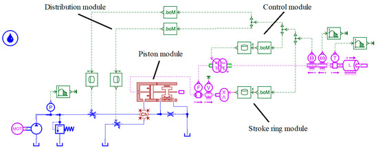
Figure 6.
Single piston hydraulic model of multiple-stroke piston motor.
During the process of building a hydraulic model, the change in the flow area is one of the key factors. When the motor is working, the oil enters the piston chamber through the oil suction and discharge window of the valve plate. As the rotor rotates, the flow area changes, as shown in Figure 7. This change directly affects the pre-boost and pressure relief in the piston chamber, which seriously affects the noise and vibration of the motor.
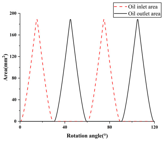
Figure 7.
The change trend of single-piston flow area.
The structure of the multiple-stroke piston motor used in this study is a double-row 6-acting 8-piston. The position of each piston on the stroke ring and the flow area of the piston chamber changes periodically, so the change in position and flow area of the single piston in the stroke ring can reflect the characteristics of all motor pistons. Then, the hydraulic model of the next piston can be obtained by increasing the rotation angle of adjacent pistons by 22.5°, and the overall hydraulic simulation model of the multiple-stroke piston motor can be obtained by analogy.
3. Influence of Elastic Deformation
3.1. Deformation Analysis
By using the liquid–solid coupling simulation model, the deformation of the stroke ring can be calculated. The coupling simulation refers to using the piston cavity pressure and rotor velocity obtained from the AMESim model as input conditions for dynamics, and then obtaining the deformation amount through the dynamic model. And the operating conditions were selected as rotor speed of 1 r/min and five different load pressures of 15 MPa, 20 MPa, 25 MPa, 30 MPa, and 35 MPa. The results are shown in Figure 8.
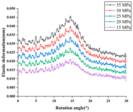
Figure 8.
Elastic deformation diagram of stroke ring.
Figure 8 shows that in the high-pressure region (0–30°), as the rotor rotates, the elastic deformation of the stroke ring shows a trend of first increasing and then decreasing, and the rate of change of elastic deformation varies in different angle ranges. This phenomenon can be explained by Equation (11), where the reaction force and the curvature radius of the stroke ring are related to its deformation and vary with the rotation angle. Meanwhile, as the load pressure increases, the deformation at each point of the stroke ring also increases, but its overall trend of change is consistent. Among them, the main factors affecting elastic deformation are the load pressure of the motor, the pressure angle of the stroke ring, and the curvature radius.
In order to obtain the deformed stroke ring curve, the deformation is superimposed onto the ideal design curve, as shown in Figure 9. Bring it into the hydraulic simulation model, the output characteristics of the motor can be analyzed.
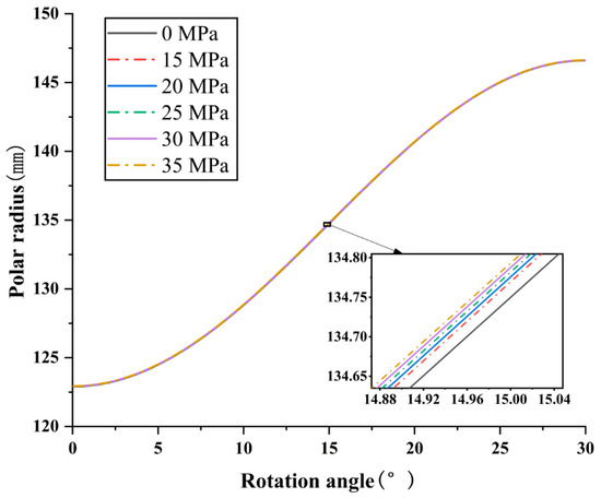
Figure 9.
Comparison of ideal working curves under different pressures.
3.2. Deformation Test Verification
To verify the correctness of deformation calculation, a test bench was built, as shown in Figure 10. The design principle of the test bench is based on the actual working situation of the roller stroke ring. And the contact between roller stroke rings is simplified as the contact between two cylinders (based on the Hertz contact theory). The material of the two cylinders is the material of the stroke ring and piston.
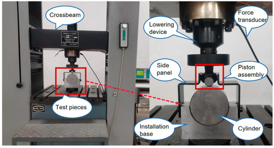
Figure 10.
Picture of deformation value test.
As shown in Figure 10, the test bench is composed of a universal testing machine whose model is CMT5105/100 KN Machine Company, a side plate, a mounting base, a cylinder, and a piston assembly. The universal testing machine produced by Wanchen Testing Company in Jinan, Shandong, China and its measurement parameters are shown in Table 3. Among them, the universal testing machine includes a crossbeam, a lowering device, extensometer, etc. The extensometer model is YYS-25/5, produced by Beijing Central Iron & Steel Research Institute in Beijing, China, with an absolute error of 0.2 μm. And the universal testing machine integrates functions of force application, deformation measurement, and data acquisition. The crossbeam is used to achieve the up and down movement of the lowering device. The lowering device is used to apply force to the specimen. The extensometer is used to collect specimen deformation. The side plate simulates the rotor column piston chamber to limit the degree of freedom of the piston. The function of installing the base is to fix the simulated cylinder of the stroke ring. After the installation of the test piece, the contact force obtained from Equation (10) under a pressure of 35 MPa was applied to the piston assembly through a lowering device. The deformation of the stroke ring at six positions was tested and compared with the simulated deformation. The deformations and the diameters of two cylindrical bodies that replace the contact between the ring and the rollers at six different position is shown in Table 4.
Table 3.
Universal testing machine measurement parameters.
Table 4.
Error between simulated deformation value and experimental deformation value.
The reasons for the errors in the experiment are as follows: 1. Error of universal testing machine in load application and deformation measurement. 2. The deformation of the side plate causes slight lateral displacement of the piston components, but when converted to longitudinal displacement, it can be ignored. Therefore, the maximum error between the experiment and simulation is acceptable and can truly reflect the actual deformation of the stroke ring.
3.3. Influence of Deformation on Motor Output Characteristics
In the multiple-stroke piston motor, the stroke ring curve mostly determines the output characteristics, noise, and life of the motor. Practically, the elastic deformation of the stroke ring curve causes the piston to deviate from the theoretically designed curve, causing a change in the pressure angle, and further affects the contact force between the stroke ring and the roller. The stroke ring curve after elastic deformation under different loads is imported into the hydraulic simulation model to analyze the piston chamber pressure and motor output characteristics before and after deformation of the ideal design curve (the actual working curve is formed after the ideal design curve is deformed).
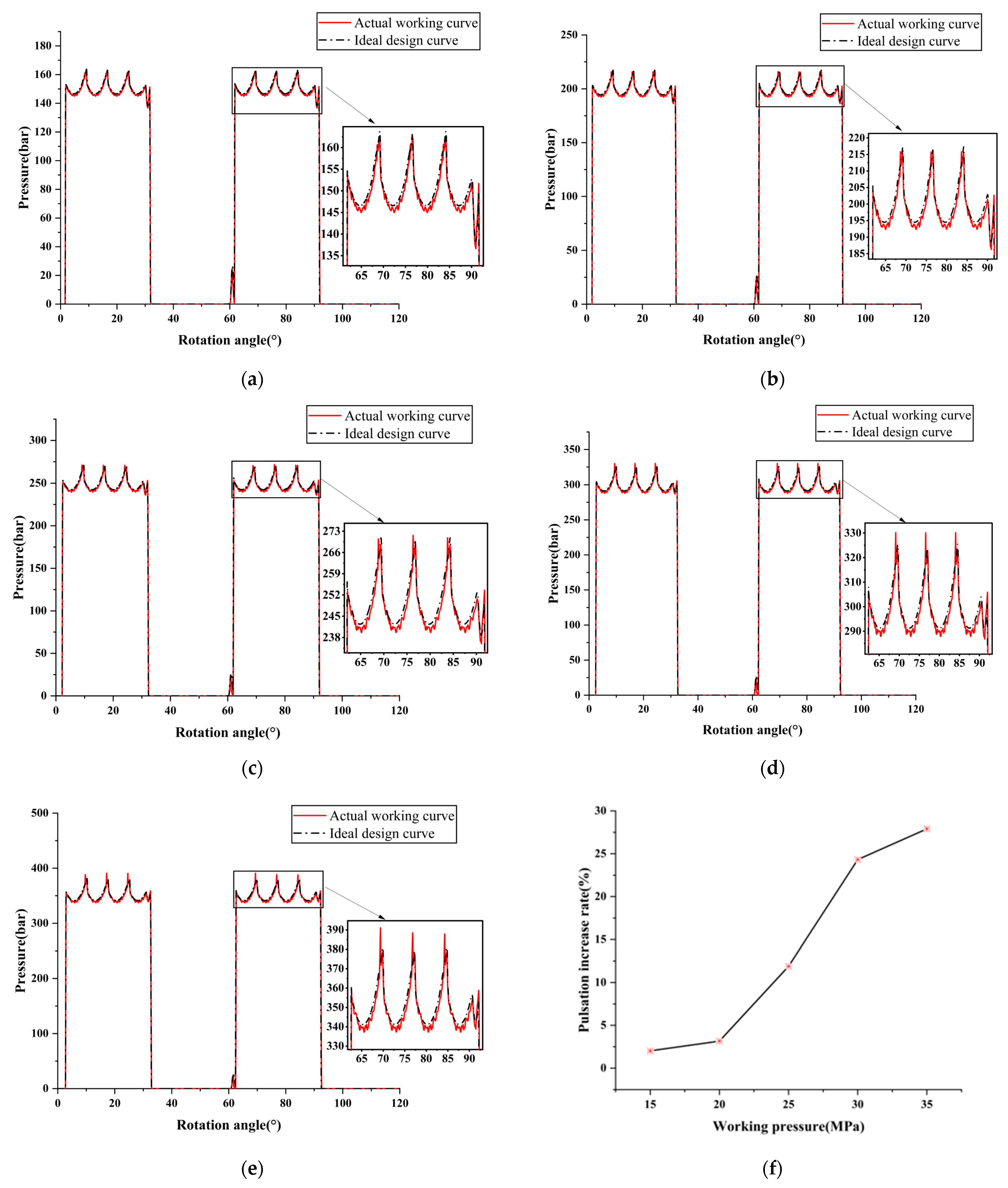
Under the condition of 1 r/min speed and different load pressure, the effect of the elastic deformation of the stroke ring on the pressure in the motor piston chamber is shown in Figure 11. It can be seen that the pressure of the piston chamber of the actual working curve oscillates, which is caused by factors such as nonlinear elastic deformation of the stroke ring curve. And it is obvious from Figure 11f that the pulsation growth rate of the piston chamber pressure is slow, between 15 and 20 MPa. The pulsation growth rate is fast, between 20 and 30 MPa. Between 30 and 35 MPa, the pulsating growth rate gradually stabilizes. Among them, at 35 MPa, the pulsation growth rate is relatively large at 27.9%.
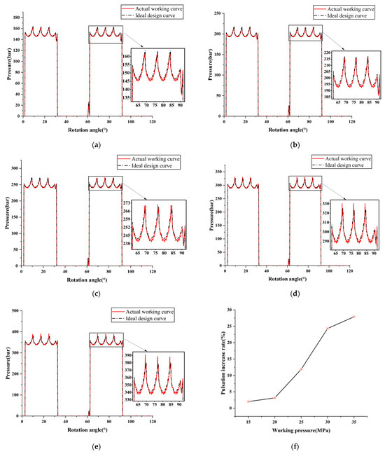
Figure 11.
Pressure comparison diagram of piston chamber before and after deformation of ideal design curve under different pressures: (a) 15 MPa; (b) 20 MPa; (c) 25 MPa; (d) 30 MPa; (e) 35 MPa; (f) pressure pulsation increase rate.
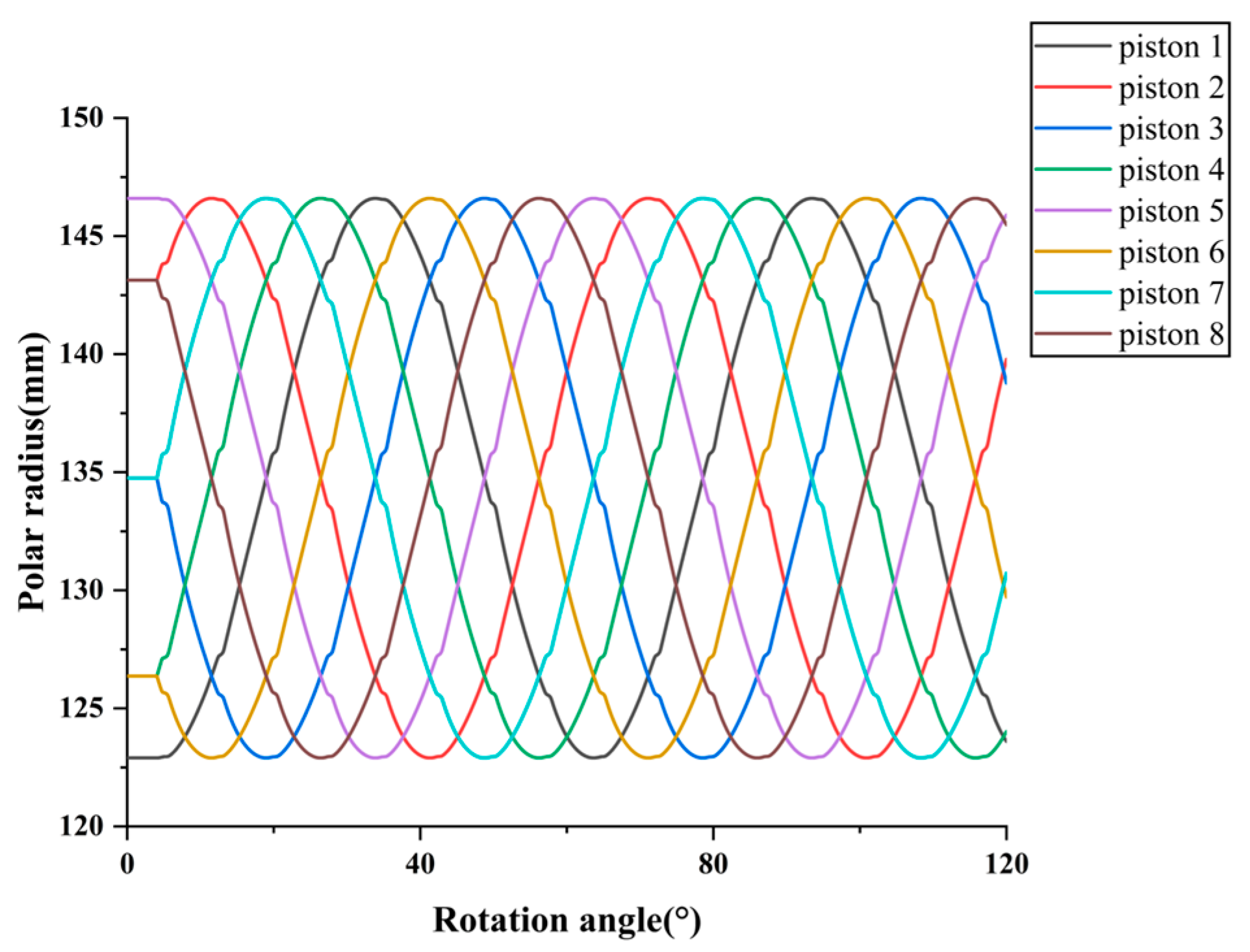
In order to analyze where the maximum pulsation of the motor occurs, the piston displacement motion curve needs to be obtained, as shown in Figure 12. Since the motor can be divided into two groups of equivalent pistons according to the phase angle, only eight pistons need to be simulated for the analysis.
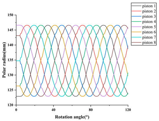
Figure 12.
Displacement curves of different pistons.
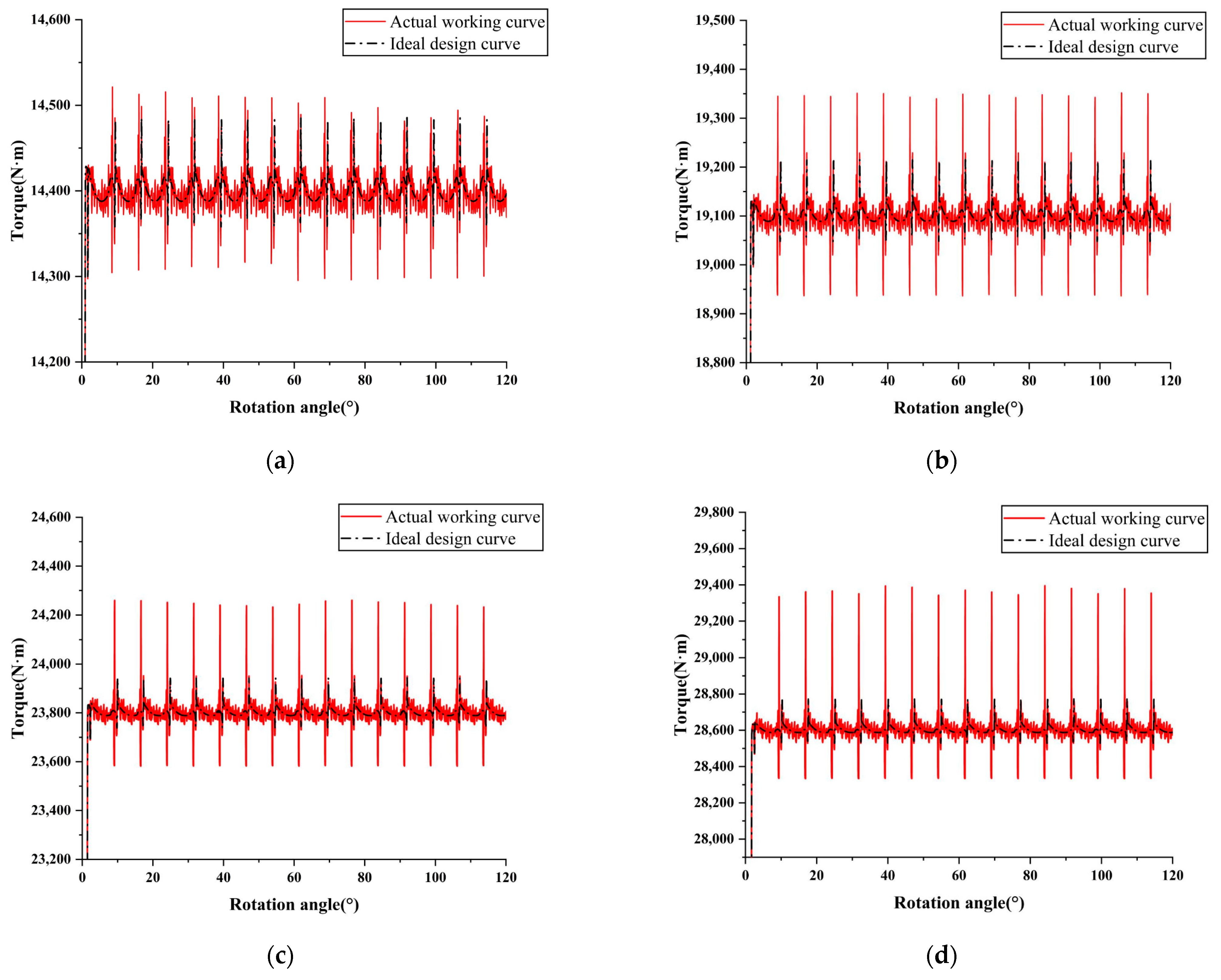
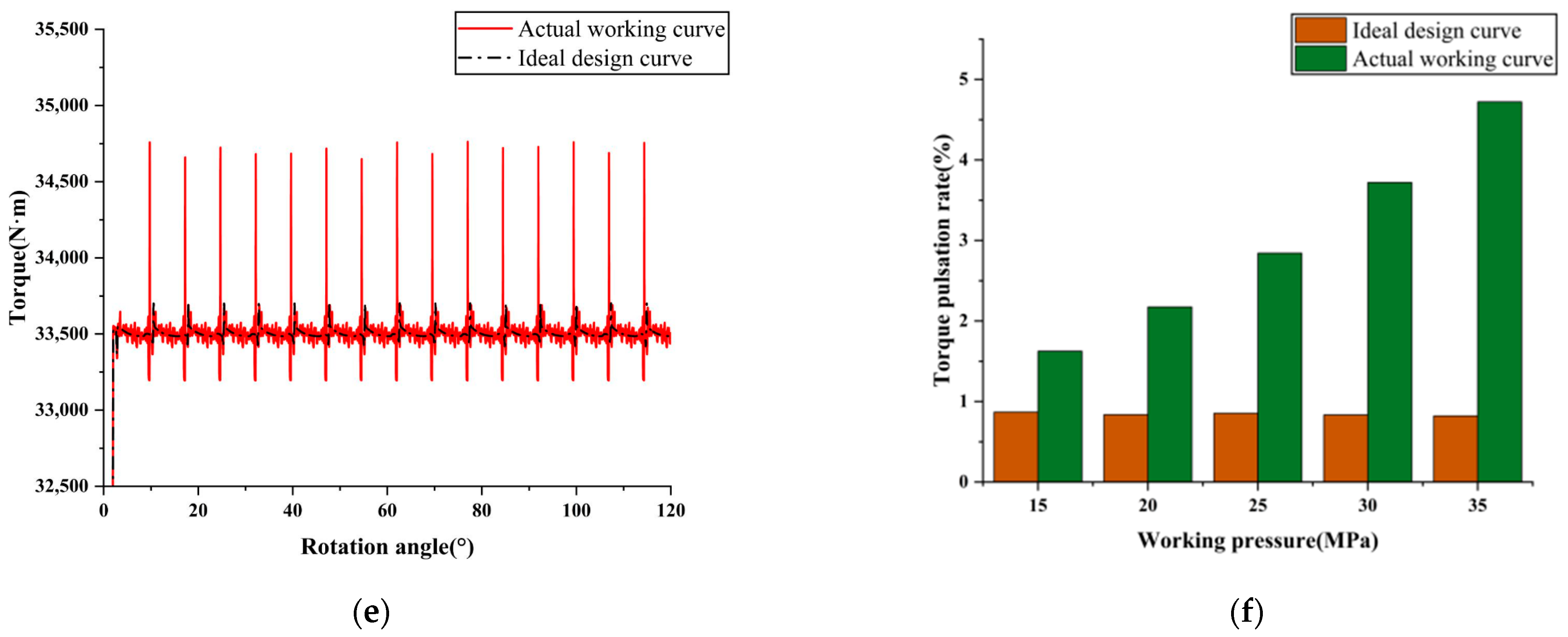
The effect of elastic deformation on the motor output torque was analyzed under the working conditions of 1 r/min speed and different load pressure as shown in Figure 13.
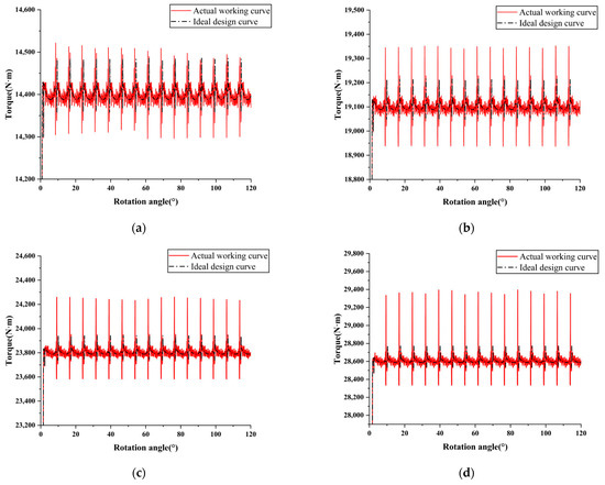
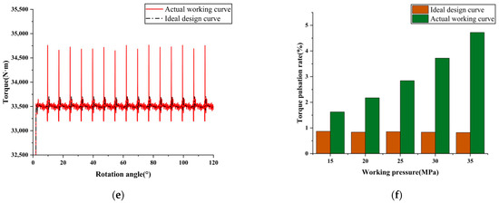
Figure 13.
Comparison of output torque before and after deformation of ideal design curve under different pressures: (a) 15 MPa; (b) 20 MPa; (c) 25 MPa; (d) 30 MPa; (e) 35 MPa; (f) torque pulsation rate comparison diagram.
Combined with Figure 12, it can be found that the maximum position of torque pulsation occurs in the conversion zone of high and low pressure. This phenomenon is caused by the impact of oil pressure in the conversion zone. This change also leads to the corresponding sudden change of stroke ring deformation and increases the pulsation of the piston chamber pressure, and finally leads to the large fluctuation of the motor output torque. And from the torque pulsation rate Figure 13f, it can be seen that as the load pressure increases, the motor output torque pulsation rate continues to increase. When the load pressure increases from 15 MPa, 20 MPa, 25 MPa, 30 MPa to 35 MPa, the output torque pulsation caused by the elastic deformation of the stroke ring gradually increases from 1.626%, 2.175%, 2.844%, 3.720%, and 4.723%. Obviously, for the multiple-stroke piston motor applied to high-pressure working conditions, the deformation of the stroke ring is a considerable factor in the design of a stroke ring curve.
4. Numerical Analyses Based on Deformation Compensation Optimization
A deformation compensation optimization design method is proposed to improve the dynamic characteristics of the multiple-stroke piston motor. This method is achieved by overlaying an offset along the normal direction on the ideal design curve in advance, so that the contact point trajectory between the piston component and the stroke ring during the working process approaches the ideal design curve, thereby reducing the output torque pulsation of the motor.
4.1. Compensation Method
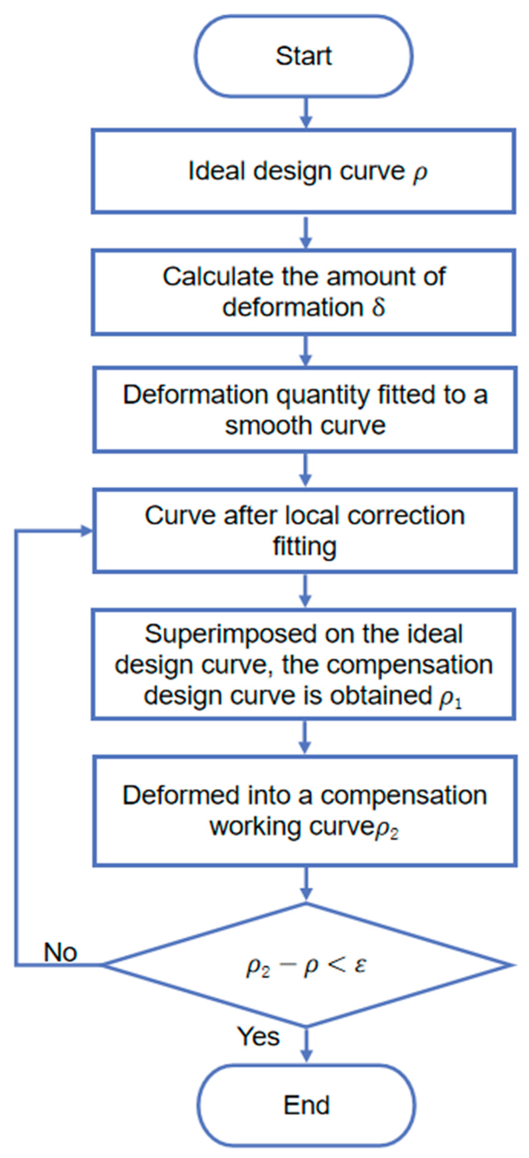
The flow chart of the optimization method for compensating the deformation of the stroke ring is shown in Figure 14.
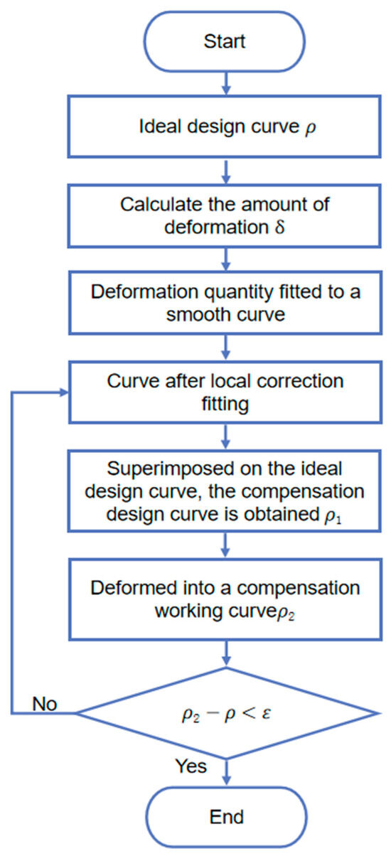
Figure 14.
Stroke ring deformation compensation method flow chart.
The optimization process is as follows: Firstly, the finite element simulation of the ideal design curve is carried out to obtain the deformation value and fit it into a smooth curve, then the fitted curve is locally corrected. Secondly, the locally corrected fitted deformation value curve is superimposed on the theoretical design curve to obtain the compensation design curve . Thirdly, introduce the curve after deformation compensation into finite element software for deformation calculation, and obtain the actual working curve . Finally, if the condition is met, , then output the compensation design curve . Otherwise, continue iterative correction.
4.2. Result Verification
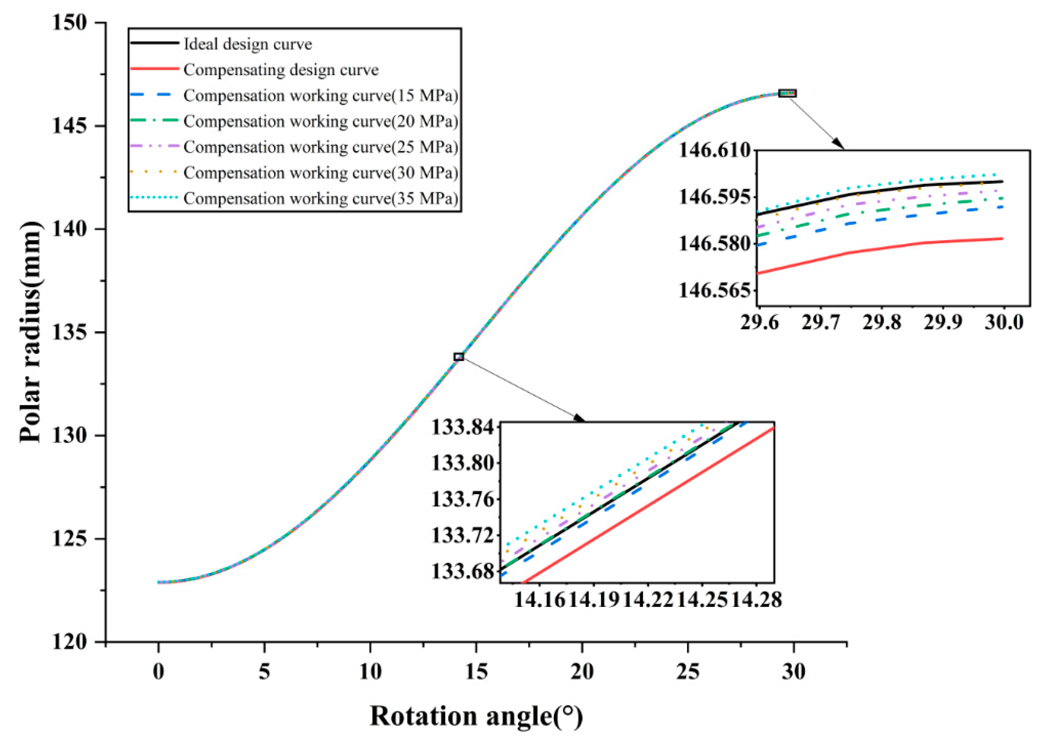
Due to the requirements of the main machine system, the iterative design of the motor stator guide curve is optimized at 25 MPa and 1 r/min operating conditions. The compensation design curve is imported into the simulation model to investigate its deformation and output characteristics at different load pressures. The compensation design curves and their deformation operating curves at different pressures are shown in Figure 15.
Figure 15.
Stroke ring deformation compensation curve results.
As shown in Figure 15, although there is a large gap between the compensating design curve and the ideal design curve when working without pressure, the actual working curve can be close to the ideal curve after the deformation of the high-pressure load. The deviation of the operating curve from the ideal curve at different pressures in different areas of the curve is not the same, and it is due to the nonlinear deformation of the curve and the discrete deviation of the fitted curve. Combined with the variation in the movement characteristics of the piston in different areas, the different distribution of this deviation further affects the output characteristics of the motor. The torque pulsation rate therefore needs to be further analyzed to verify the reasonableness of the curve.
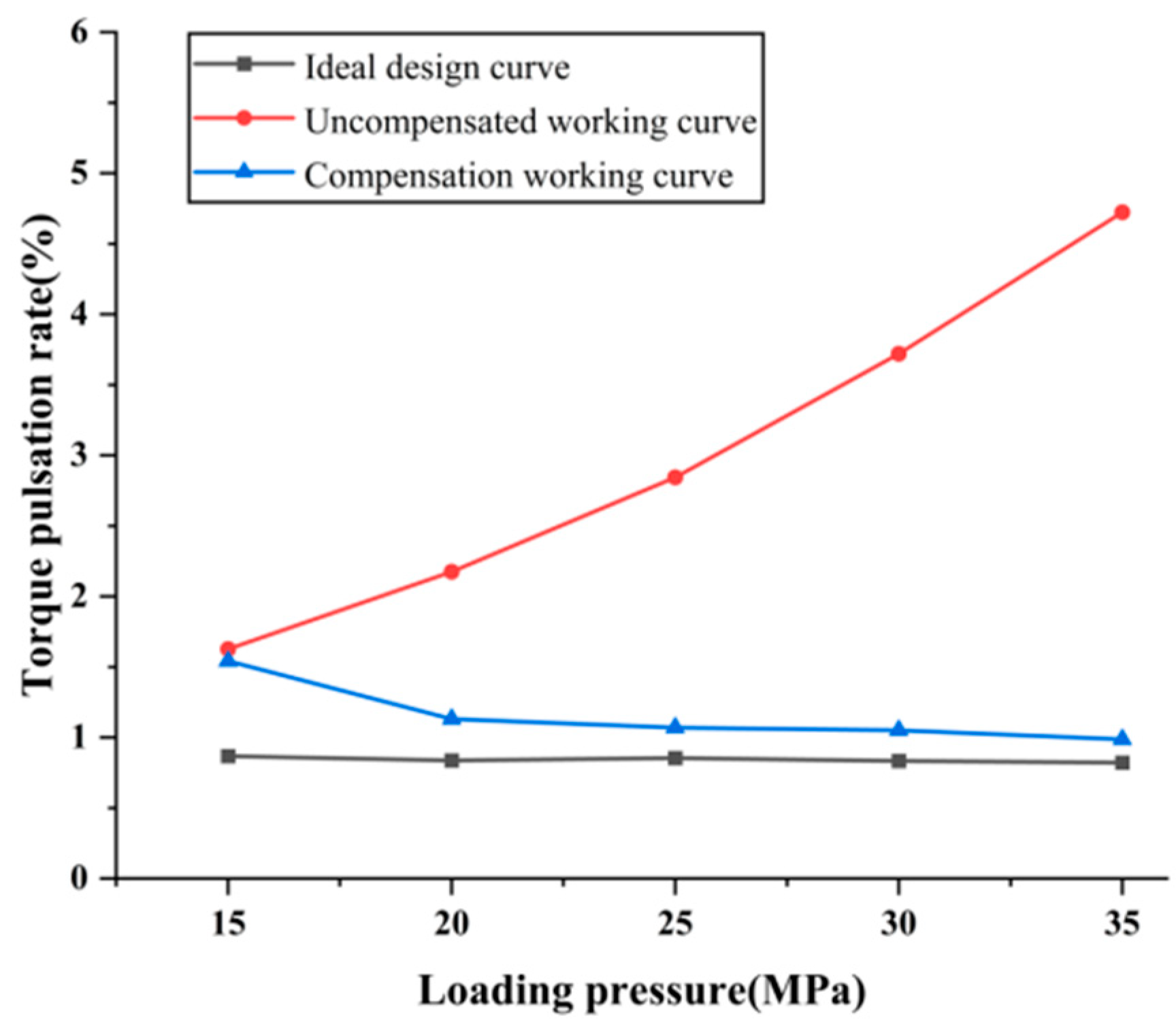
In the hydraulic simulation model, the output torque pulsation rate of the stroke ring compensation working curve under different load pressures was simulated. The results are shown in Figure 16; note that the uncompensated working curve is an ideal curve that deforms during operation, but the ideal design curve does not. As shown, although the pulsation rate of the motor with the ideal design curve is small under the selected five working conditions, there is a significant deviation between the pulsation rate of an uncompensated working curve motor and the ideal due to deformation. The deviation in pulsation rate increases with the increase in pressure, with a maximum deviation of 3.902% at 35 MPa. Opposite to that, the deviation of pulsation rate of a motor with compensation working curve is only 0.165% at 35 MPa, and this motor exhibits good performance above 20 MPa. This further verifies the effectiveness of the design method.

Figure 16.
Comparison of torque pulsation rate of each stroke ring curve under different pressures.
5. Conclusions
In this study, the influence of the elastic deformation of the stroke ring curve on the output torque of the motor and the pressure pulsation of the piston chamber was analyzed, and the numerical verification method of deformation was proposed. The following conclusions can be obtained:
- A finite element simulation model was established to calculate the elastic deformation value of the stroke ring curve, which was verified using tests;
- The elastic deformation of the stroke ring curve has a significant effect on the output torque of the motor. Under the condition of 35 MPa, the pulsation rate of the uncompensated working curve is 3.902% higher than that of the ideal design curve;
- An effective deformation compensation optimization method was proposed. The results show that the pulsation rate of the deformation-compensated working curve was significantly reduced compared with the uncompensated working curve, and the reduction rate of torque pulsation reached 79.12% under 35 MPa working conditions;
- The research contents of this paper can provide reference for structural optimization and performance improvement of multiple-stroke piston motor used in military, marine, and engineering machinery and other occasions with high requirements for impact and noise;
- In the future, based on this research, factors such as oil film thickness and fatigue stress can be considered to better optimize the service life and performance of the multiple-stroke piston motor.
Author Contributions
Conceptualization, G.A., K.G. and H.D.; software, K.G. and B.L.; validation, G.A., K.G., B.L. and Z.H.; writing—original draft preparation, K.G.; writing—review and editing, G.A., B.L. and L.L.; supervision, G.A. and K.G. All authors have read and agreed to the published version of the manuscript.
Funding
This research has been supported by the National Key R&D Program of China (Grant No.2021YFB3400502).
Data Availability Statement
The data are available upon request from the corresponding author.
Conflicts of Interest
The authors declare no conflicts of interest.
References
- Kogler, H.; Plöckinger, A.; Foschum, P. Cybernetic Proportional System for a Hydraulic Cylinder Drive Using Proportional Seat-Type Valves. Actuators 2023, 12, 370. [Google Scholar] [CrossRef]
- Tao, J.; Wang, H.; Liao, H.; Yu, S. Mechanical design and numerical simulation of digital-displacement radial piston pump for multi-megawatt wind turbine drivetrain. Renew. Energy 2019, 143, 995–1009. [Google Scholar] [CrossRef]
- Lu, J.; Gu, C.; Zhao, Y.; Tan, C.; Lu, Y.; Fu, C. Refined Modeling Method and Analysis of an Electromagnetic Direct-Drive Hydrostatic Actuation System. Actuators 2022, 11, 281. [Google Scholar] [CrossRef]
- Zhu, Q. Radial piston motor cam ring curve design analysis. Mech. Res. Appl. 2002, 1, 34–35. [Google Scholar]
- Akers, A.; Gassman, M.; Smith, R. Hydraulic Power System Analysis; CRC Press: Boca Raton, FL, USA, 2006. [Google Scholar]
- Jirawattana, P. Design, Simulation, Fabrication and Testing of a Low-Speed High-Torque (LSHT) Pump/Motor for a Hydrostatic Vehicle. Ph.D. Thesis, The University of Wisconsin-Madison, Madison, WI, USA, 2000. [Google Scholar]
- Chen, Z.R. Theory, Calculation and Design of Low Speed and High Torque Hydraulic Motor; China Machine Press: Beijing, China, 1989. [Google Scholar]
- Ivantysyn, J.; Ivantysynova, M. Hydrostatic Pumps and Motors: Principles, Design, Performance, Modelling, Analysis, Control and Testing; Akademia Books International: New Delhi, India, 2001. [Google Scholar]
- Dasgupta, K.; Mukherjee, A.; Maiti, R. Theoretical and experimental studies of the steady state performance of an orbital rotor low-speed high-torque hydraulic motor. Proc. Inst. Mech. Eng. Part A J. Power Energy 1996, 210, 423–429. [Google Scholar] [CrossRef]
- Yu, H.Y.; Zhong, H.T.; Li, S. The analysis on the flow pulsation of radial piston motor with the modified heart-shaped curve as inner curve. J. Harbin Inst. Technol. 2012, 44, 44–48. [Google Scholar]
- Liu, X.B.; Chen, X.Y.; Zhan, C.C.; Liu, Y. Influence of full flow coefficient on output torque of hydraulic motor with inner curve radial piston. J. Wuhan Univ. Sci. Technol. 2017, 40, 290–294. [Google Scholar]
- Zhang, X.L.; Zhang, J.H.; Zhang, H.J.; Xu, B. Optimized design of cam ring curve of cam lobe radial-piston motor. J. Huazhong Univ. Sci. Technol. 2021, 49, 30–35. [Google Scholar]
- Nguyen, T.N.; Kurtenbach, S.; Hüsing, M.; Corves, B. A general framework for motion design of the follower in cam mechanisms by using non-uniform rational B-spline. Mech. Mach. Theory 2019, 137, 374–385. [Google Scholar] [CrossRef]
- Xin, J.B. Research on Generalized Stator Orbit Curve of Radial Piston Motor. Master’s Thesis, Nanchang University, Nanchang, China, 2019. [Google Scholar]
- Khalifa, M.Z. The effects of multi-layers surfaces on the elastic deformation of journal bearing. J. Eng. Sci. Technol. 2021, 16, 3521–3533. [Google Scholar]
- Zhang, Y.; Chen, G.; Wang, L. Effects of thermal and elastic deformations on lubricating properties of the textured journal bearing. Adv. Mech. Eng. 2019, 11, 10. [Google Scholar] [CrossRef]
- Linjamaa, A.; Lehtovaara, A.; Larsson, R.; Kallio, M.; Söchting, S. Modelling and analysis of elastic and thermal deformations of a hybrid journal bearing. Tribol. Int. 2018, 118, 451–457. [Google Scholar] [CrossRef]
- Li, W.; Wang, L.; Yu, G. Force-induced deformation prediction and flexible error compensation strategy in flank milling of thin-walled parts. J. Mater. Process. Technol. 2021, 297, 117–258. [Google Scholar] [CrossRef]
- Huang, H.W.; Tsai, M.S.; Huang, Y.C. Modeling and elastic deformation compensation of flexural feed drive system. Int. J. Mach. Tools Manuf. 2018, 132, 96–112. [Google Scholar] [CrossRef]
- Wang, X.; Li, Z.; Bi, Q.; Zhu, L.; Ding, H. An accelerated convergence approach for real-time deformation compensation in large thin-walled parts machining. Int. J. Mach. Tools Manuf. 2019, 142, 98–106. [Google Scholar] [CrossRef]
- Petrović, R.; Pezdirnik, J.; Banaszek, A.; Đuričić, L. Influence of compressibility of working fluid on hydrodynamic processes in the axial piston pump with combined distribution/flow of working fluid. In Proceedings of the 2011 International Conference on Fluid Power and Mechatronics, Beijing, China, 17–20 August 2011; pp. 335–339. [Google Scholar]
- Nakhatakyan, F.G. Solution of a plane contact problem of the theory of elasticity on the basis of an elastic half-space model. J. Mach. Manuf. Reliab. 2011, 40, 458–462. [Google Scholar] [CrossRef]
- Nor, K.M.; Ibrahim, M.N.; Choiron, M.A. An overview of fracture mechanics with ANSYS. Mech. Eng. 2018, 10, 59–67. [Google Scholar]
- Lei, J.; Su, B.; Zhang, S.; Yang, H.; Cui, Y. Dynamics-Based Thermal Analysis of High-Speed Angular Contact Ball Bearings with Under-Race Lubrication. Machines 2023, 11, 691. [Google Scholar] [CrossRef]
- Banaszek, A.; Petrović, R.; Zylinski, B. Finite element method analysis of pipe material temperature changes influence on line expansion loops in hydraulic installations on modern tankers. Therm. Sci. 2011, 15, 81–90. [Google Scholar] [CrossRef]
- Liang, Q.; Wang, W.; Zhai, Y.; Sun, Y.; Zhang, W. Modeling and Fault Simulation of a New Double-Redundancy Electro-Hydraulic Servo Valve Based on AMESim. Actuators 2023, 12, 417. [Google Scholar] [CrossRef]


Disclaimer/Publisher’s Note: The statements, opinions and data contained in all publications are solely those of the individual author(s) and contributor(s) and not of MDPI and/or the editor(s). MDPI and/or the editor(s) disclaim responsibility for any injury to people or property resulting from any ideas, methods, instructions or products referred to in the content. |
© 2024 by the authors. Licensee MDPI, Basel, Switzerland. This article is an open access article distributed under the terms and conditions of the Creative Commons Attribution (CC BY) license (https://creativecommons.org/licenses/by/4.0/).