Article

Mining Electric Shovel Working Device Configuration Synthesis and Performance Analysis

1
College of Mechanical and Vehicle Engineering, Taiyuan University of Technology, Taiyuan 030024, China
2
Shanxi Province Engineer Technology Research Center for Mine Fluid Control, Taiyuan 030024, China
3
National-Local Joint Engineering Laboratory of Mining Fluid Control, Taiyuan 030024, China
*
Author to whom correspondence should be addressed.
Actuators 2023, 12(8), 317; https://doi.org/10.3390/act12080317
Submission received: 14 June 2023 / Revised: 30 July 2023 / Accepted: 3 August 2023 / Published: 5 August 2023
(This article belongs to the Special Issue Innovative and Intelligent Actuation for Heavy-Duty Applications)

Abstract

:
Mining electric shovels (MES) are one of the key pieces of equipment for mining, and their comprehensive performance plays an important role in mining efficiency. Based on the screw theory, this paper proposes a comprehensive configuration method for an MES working device and selects a new mining electric shovel working device with a larger excavation range, taking the working device as an example for dimensional optimization and simulation analysis. Firstly, based on the closed-loop vector equation, the position inverse solution of the mechanism is analyzed, and the correctness of the position equation is verified by the simulation and by numerical solutions. Then, the constraints of the mechanism are analyzed, and the numerical method and the position equation are combined to solve for the workspace of the mechanism. The dimensional parameters of the mechanism are optimized by genetic algorithms. The workspace of the optimized working device is increased by 13.4789%. Finally, the mining results of the two MES, the working devices, are simulated and verified by experiment. It is shown that the experimental results are basically consistent with the simulation results. The excavation quality difference of the two working devices are 2.02% and 2.20%, which verifies the correctness of the kinematics equation of the working device and the feasibility of the new working device.

1. Introduction

Mining electric shovels (MES), also known as electro-mechanical excavators and electric rope shovels, are widely used in open-pit mining operations because of their compact structure, high working capacity, large digging range and adaptability to the environment [1]. The working devices of MES in the excavation process are mainly the crowd and hoist mechanisms. With the widespread use of MES, more requirements are put forward for the working device of the MES. Therefore, it is necessary to analyze the configuration synthesis of the working device of the MES and provide a method for the structural innovation of the shovel, and thereby to optimize the parameters and improve work efficiency.
The configuration synthesis of mechanisms is an effective tool for mechanism design and structural innovation. The purpose of configuration synthesis is to find the relationship between the motion subsets and the position of the motion subsets in space from the expected degrees of freedom or the expected functional properties, and to design a mechanism type that satisfies the conditions. Herve [2], a French scholar, first introduced the Lie group theory in the field of configuration synthesis and proposed a method of motion synthesis of displacement subgroups based on group theory. Li et al. [3] and Meng et al. [4] analyzed and synthesized parallel mechanisms based on the Lie group of displacements. Gogu [5,6,7] analyzed a configuration synthesis method for parallel mechanisms based on the linear transformation idea. Yang et al. [8] proposed a configuration synthesis method based on single open chain (SOC) composition principle. Based on the constraint screw theory, Kong and Gosselin [9,10] proposed a virtual chain configuration synthesis method to solve the configuration synthesis problem of parallel mechanisms. Han et al. [11] synthesized four new configurations of annular deployable antennas by using the screw-theory constraint synthesis method. Compared with other configuration synthesis methods, the screw-theory-based constraint synthesis method has the advantages of clear physical meaning, simple mathematical expression and algebraic operations.
Kinematics analysis of the mechanism is the basis for studying the performance of the mechanism, thereby improving it, and designing new mechanisms. Zhao et al. [12] analyzed the inverse kinematics of a hyper-redundant bionic trunk-like robot by a closed-loop vector equation. Wang et al. [13] proposed a new 5-DOF parallel mechanism with 5PUS-UPU. The position equations of the mechanism are analyzed by the closed-loop vector method, and the mapping relationships of position, velocity and acceleration are obtained. Based on the closed-loop vector method, Chen et al. [14] constructed a kinematic model of an over-constrained parallel mechanism and derived the velocity Jacobian matrix of the mechanism. The main analytical methods for the workspace are the boundary search [15,16,17] and the numerical method [18,19,20]. Among them, the numerical method can solve the problem by programming, which has the advantages of high efficiency and accuracy. Therefore, this paper uses the numerical method to analyze the workspace of the MES.
At present, many experts and scholars have carried out a substantial amount of research on the configuration synthesis of mechanisms, but for the time being, there is no report on the configuration synthesis of the MES. In this paper, based on the screw theory, we propose a configuration synthesis method for MES working devices and optimize the mining electric shovel working device with a larger excavation range, and then take the working device as an example for dimensional optimization and simulation analysis. The first part of the paper introduces the background of the study. The second part analyses the configuration synthesis method of the MES working devices. The third part solves the position equation of the working device. In combination with the constraints of the mechanism, the numerical method is used to solve its workspace. The fourth part analyses the influence of rod parameters on the working space and optimizes the working device dimensions based on genetic algorithms. In the fifth part, two kinds of scaled-down model test bench of MES were built. Simulation analysis and experimental verification are carried out on the excavation results of the two MES, the working devices. Finally, a summary of the full paper is presented.

2. Mining Electric Shovel Working Device Configuration Synthesis Based on Screw Theory

2.1. Overview of the Screw Theory

According to the screw theory [21,22], any motion can be represented by a screw. A unit screw in space can be denoted as a vector, and its expression is as follows:
S = S S 0 + h S = S r × S + h S
where S means the screw; S is the direction vector along the screw axis; S 0 denotes the dual part of the screw; r is the position vector of any point on the screw axis; and h is the pitch of the screw.
When the pitch of the screw h = 0, the screw can be used to represent the kinematic screw of the revolute pair (R) in space. When the pitch of the screw h → ∞, the screw can be used to represent the kinematic screw of the prismatic pair (P) in space.
The prismatic (P) and revolute (R) pair of the mechanism are single-degree-of-freedom kinematic parts, while the cylindric pair(C), universal joint (U), spherical pair (S) and other compound parts can be regarded as combinations of single-degree-of-freedom kinematic parts.
For any two screws S = ( S , S 0 ) and S r = ( S r , S 0 r ) in space, the reciprocal product equation is
S S r = S S 0 r + S 0 S r
where —the reciprocal product operator.
If the solution of the equation is 0, the screw S and S r are said to be reciprocal. The reciprocal screw theory shows that if screw S 1 , S 2 , S 3 ,…, S m represents the kinematic screw of a branch chain of the mechanism, then screw S r represents the constraint screw of that branch chain.
The configuration synthesis method based on screw theory is as follows: Firstly, the motion screw system of the mechanism is listed according to the expected degrees of freedom of the mechanism. Then, based on the reciprocal screw theory, the constraint screw system of the mechanism is found, and the kinematic screw and constraint screw of the branched chain are calculated. Finally, the branch chain structure is constructed, and the branch chain structure is optimally configured to obtain the new configuration of the mechanism.

2.2. Analysis of Mining Electric Shovels: A Working Device

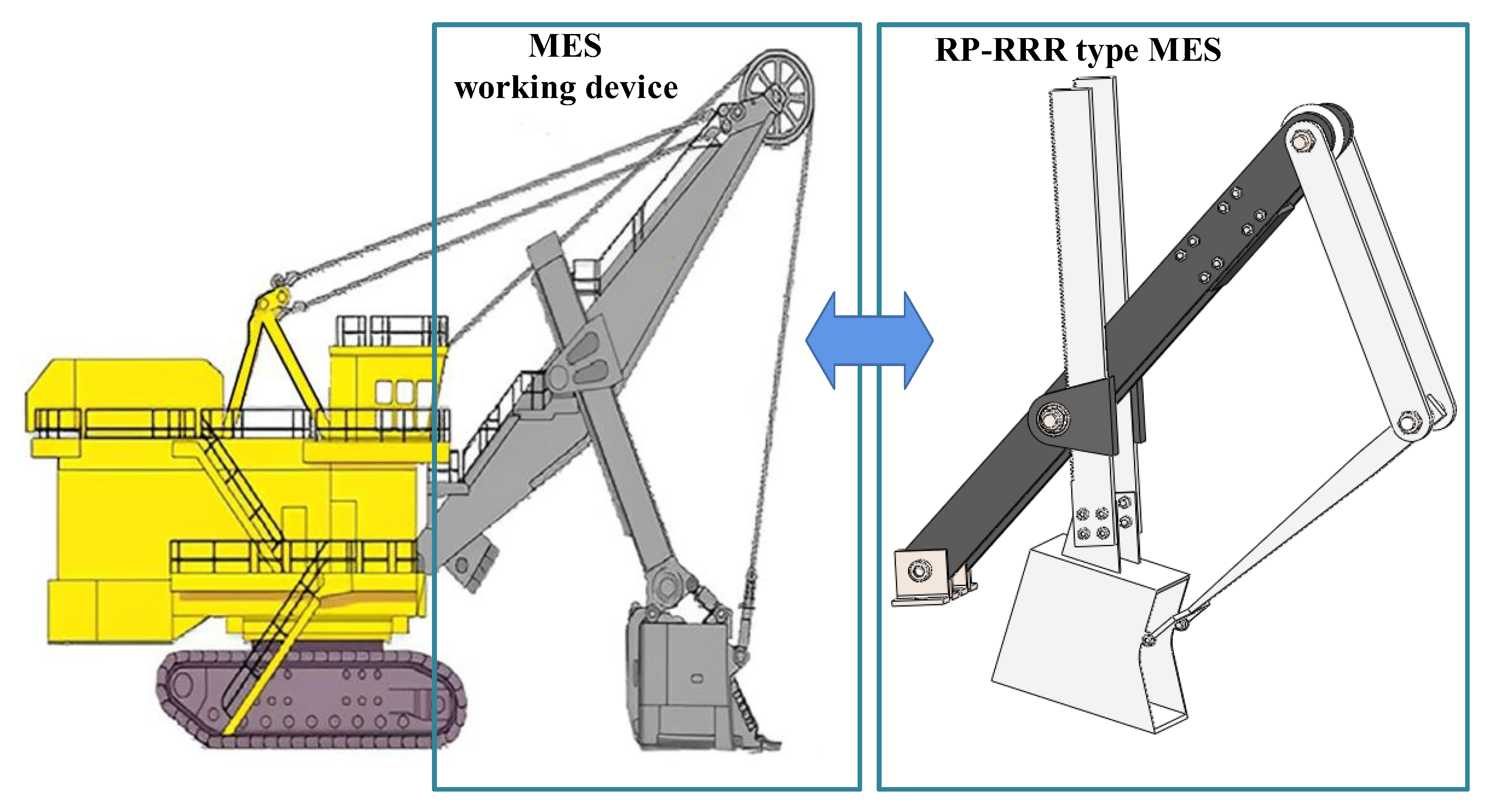
The working devices of the MES are mainly the crowd and hoist mechanisms, of which the main components are boom, saddle, push shaft, bucket rod, pushing gear, bucket, sheave pulley and lifting wire rope, as shown in Figure 1.
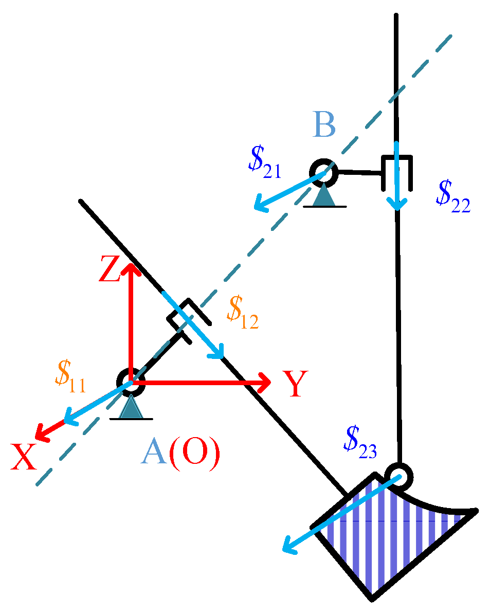
With the boom as the frame, and the bucket rod and bucket as the moving platform, the structure of the rack and pinion in the pushing mechanism is simplified to one prismatic (P) and one revolute (R) pair, and the structure of the lifting wire rope and sheave pulley in the lifting mechanism is simplified to one prismatic (P) and two revolute (R) pairs. The brief diagram is shown in Figure 2.
In Figure 2, the motion screw system OXYZ is established with the point A as the coordinate origin, where the X-axis is perpendicular to the paper surface and faces outward, and the Y-axis and Z-axis represent the horizontal and vertical directions, respectively. In the working device of the MES, subchain I is the RP branch chain structure, and subchain II is the RPR branch chain structure. Based on the screw theory, the kinematic screw of each branch chain structure in the working device is analyzed, and then the constrained screw of each branch chain can be found according to the reciprocal product equation, as shown in Table 1. In Table 1, ai and bi (i = 1, 2, 3, 4) represent the coordinates of a point on the axis of the screw.
A combined analysis of the constrained screw system of subchain I and subchain II shows that the moving platform of the working device will be subject to four constraint screws:
S 1 r = 1 , 0 , 0 , 0 , 0 , 0 S 2 r = 0 , 0 , 0 , 0 , 1 , 0 S 3 r = 0 , 0 , 0 , 0 , 0 , 1 S 4 r = 0 , b 1 , a 1 , 0 , 0 , 0
Therefore, there are three common constraints for the moving platform of the working device, namely S 1 r , S 2 r and S 3 r . The degrees of freedom of the working device can be calculated according to the GK formula [23]:
M = 3 × 5 5 1 + 5 = 2
Combined with the constraint screw of the moving platform, it can be seen that the moving platform is subject to four independent constraints. Therefore, to obtain a new configuration of the MES requires one rotational degree of freedom and one translational degree of freedom.

2.3. Configuration Synthesis of MES, in a Working Device

As the moving platform of the working device of the MES is subject to four independent constraints, there are two ways of synthesizing its mechanism type. Integrated solution I: a new configuration of the electric shovel is completed using one branch chain to provide all the constraints and two six-degree-of-freedom branch chain structures to provide the drive. Integrated solution II: consisting of two branched chains, the two active branched chains apply drive and restraint together.

2.3.1. Synthesis Scheme I

New configurations of MES are synthesized by a three-bar strut structure. In order to simplify the analysis, the structure of the passive branch is considered as the RP structure, and a new configuration is synthesized by using a 6-degree-of-freedom branch structure with two connecting rods and three kinematic pairs. The active branches of 6 degrees of freedom are shown in Table 2.
According to the screening conditions of the branch chain, some unreasonable branch structure types are removed:
(1) It is necessary to ensure that the mechanism can maintain the advantages of high stiffness and low inertia.
(2) The kinematic pair connected to the moving platform needs to be connected by the spherical pair as much as possible, so that the force of the connecting rod and the moving platform is simple.
The RUS, PUS, UPS, URS, USR, USP, RSS, PSS, CUS and SCS active branched chain structures that satisfy the conditions are obtained through optimization screening. Two active branched chains were selected from these branched chain structures, and the RP passive branched chain structure was added to form a variety of new mining shovel configurations. The MES working devices of RUS-RSS-RP, SCS-PSS-RP, URS-RUS-RP and SCS-PSS-RP synthesized by this method are shown in Figure 3.

2.3.2. Synthesis Scheme II

We use two branch chain structures with few degrees of freedom to synthesize the new configuration of the MES working device. Considering the specialty of the constraint screw S 4 r = 0 , b 1 , a 1 , 0 , 0 , 0 , and to simplify the complexity of the mining shovel configuration synthesis, branch chain 1 is selected as either an RP or SP structure, The structure of branch chain 2 provides constraints such as S 1 r , S 2 r and S 3 r that branch chain 1 missed. The branch-chain-structure type of the configuration scheme II of the MES working device is obtained, as shown in Table 3.
The MES working devices of RP-RPS, RP-RRR, SP-PRR and SP-RRR synthesized by this method are shown in Figure 4.
In summary, considering the similarity of the mechanism and the reliability of the bar mechanism, taking the RP-RRR MES working devices as an example, the kinematics and workspace performance of the mechanisms are analyzed and studied. The RP-RRR MES working devices use a linkage mechanism to lift the bucket, replacing the lifting mechanism, consisting of lifting wire rope and sheave pulley in the MES working device, as shown in Figure 5.

3. Workspace Analysis

3.1. Location Analysis and Simulation Verification

To facilitate the study of the kinematic characteristics of the MES working devices and to solve their position equation, the coordinate system is established with the push shaft in the MES working devices as the coordinate origin, as shown in Figure 6.
In Figure 6, P represents the point of the bucket tip of the MES mechanisms, O 1 is the center point of the push shaft. θ denotes the angle between the line O 1 P and the vertical direction. ρ represents the length of the line O 1 P . l 2 represents the length of the line AC. θ 2 is the angle between the rod l 3 and the horizontal line. The position of this RP-RRR-type MES working device is analyzed by a closed-loop vector equation system to solve for l 2 and θ 2 :
O 1 C + C A + A P = O 1 P O 1 O 2 + O 2 D + D B + B P = O 1 P
The structural parameters of the components in the RP-RRR-type MES working devices are given in Table 4. Based on the logarithmic screw-digging trajectory model of the MES working device, combined with the structural parameters of the given working device, the trajectory equations of the bucket tip P point of the RP-RRR-type MES working devices are defined as follows:
θ = π 36 × t + 3 ρ = ρ 0 e cot δ θ
where t: the duration of the motion, unit: second; ρ 0 : initial length of the stick; the value is 265.68 mm; δ : the angle between the tangent direction of the excavation trajectory and the stick; the value is 75°.
Table 4. Structural parameters of the RP-RRR-type MES working devices.
Parameter (Unit)ValueParameter (Unit)Value
L0 (mm)290lBP (mm)72.45
l1 (mm)24.5lAP (mm)133.71
l3 (mm)270θ0 (°)45
l4 (mm)263β1 (°)16.85
lAB (mm)68.09β2 (°)17.78
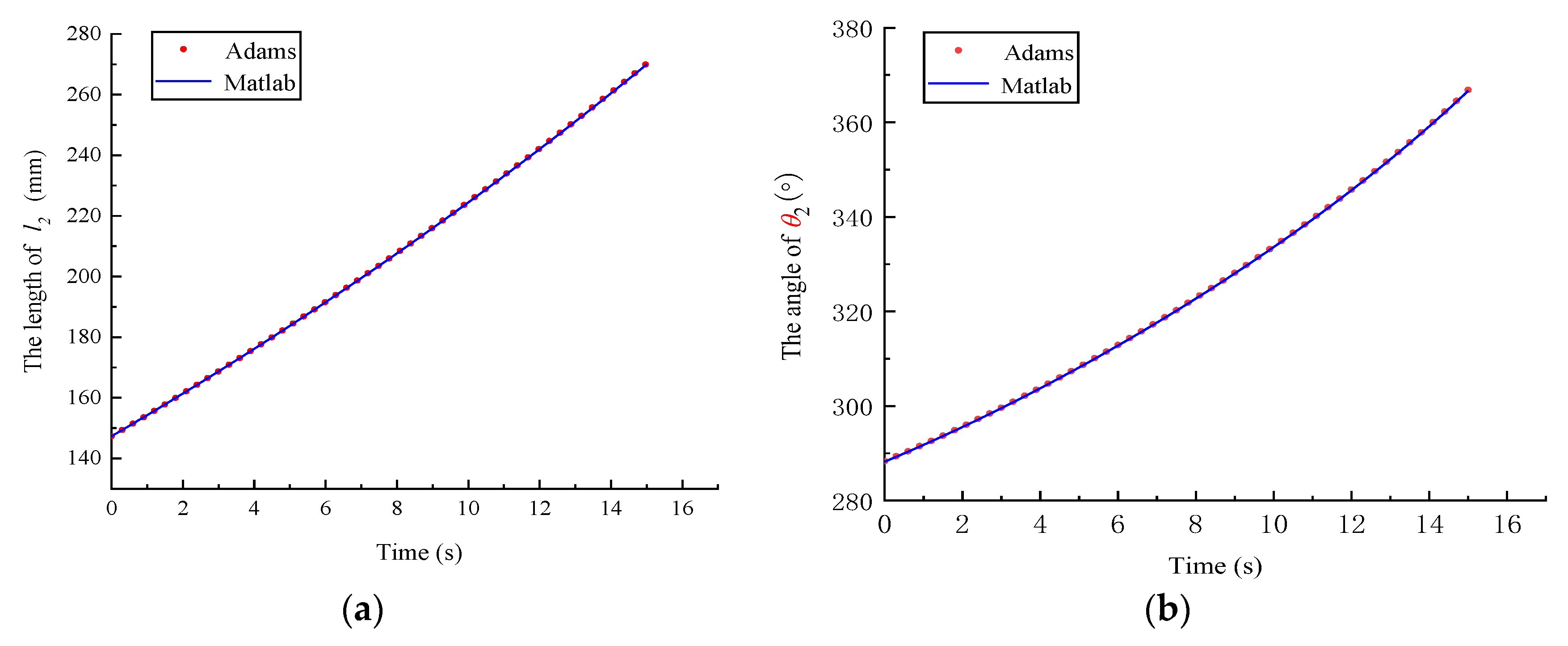
The theoretical model of the RP-RRR-type MES working devices is validated by simulation analysis based on the given excavation trajectory equation through the position equation of the RP-RRR-type MES working devices solved in the previous section, and the results are shown in Figure 7 and Figure 8.
The comparative analysis shows that the deviation between the simulation data and the theoretical value of the RP-RRR-type MES working devices basically matches within a certain error range, thus verifying the correctness of the position analysis equation.

3.2. Constraints on the Workspace

The working space of the MES working devices is the maximum range of activity that the P point of the end effector can reach. The main factors that limit its working space include corner constraints on revolute pairs in the mechanism, movement constraints on prismatic pairs and interference constraints from adjacent bars. These constraints can be defined as follows:

3.2.1. Constraints of Revolute Pairs

As shown in Figure 6, there are corner θ 1 , θ 2 and θ 3 for revolute pairs in the mechanism diagram of the working device of the mining shovel. The rotation angles of these rotation pairs need to meet the kinematics equation of the mechanism, so the range of the rotation angles is limited. Considering the different lengths of the rod and the limitations of the kinematic pairs, let the maximum angle of rotation of the revolute pair be θ max and the minimum angle of rotation be θ min ; the angle of rotation of the revolute pair is then constrained to:
θ min θ i θ max , i = 1 , 2 , 3
where θ min : the minimum angle of rotation of the revolute pair; θ max : the maximum angle of rotation of the revolute pair.

3.2.2. Constraints of Prismatic Pairs

The movement constraint of the prismatic pairs in the MES working devices also constrains the size of their working space. The maximum displacement of the prismatic pairs is l max and the maximum displacement of the prismatic pairs is l min ; the movement constraint of the prismatic pairs is then constrained to:
l min l i l max
where l min : the minimum displacement of the kinematic pairs; l max : the maximum displacement of the kinematic pairs.

3.2.3. Interference Constraints between Adjacent Rods

The rods in the MES working devices have corresponding structural dimensional parameters, which have a certain influence on the connection between adjacent rods and may interfere during the working of the mechanism. For simplicity of analysis, it is assumed that each rod is a cylindrical rod, with D denoting its rod diameter and Di denoting the shortest distance between two adjacent poles, so the following constraints should be met to avoid interference constraints between adjacent rods:
D i D , i = 1 , 2 , 3 , 4

3.3. Workspace Analysis

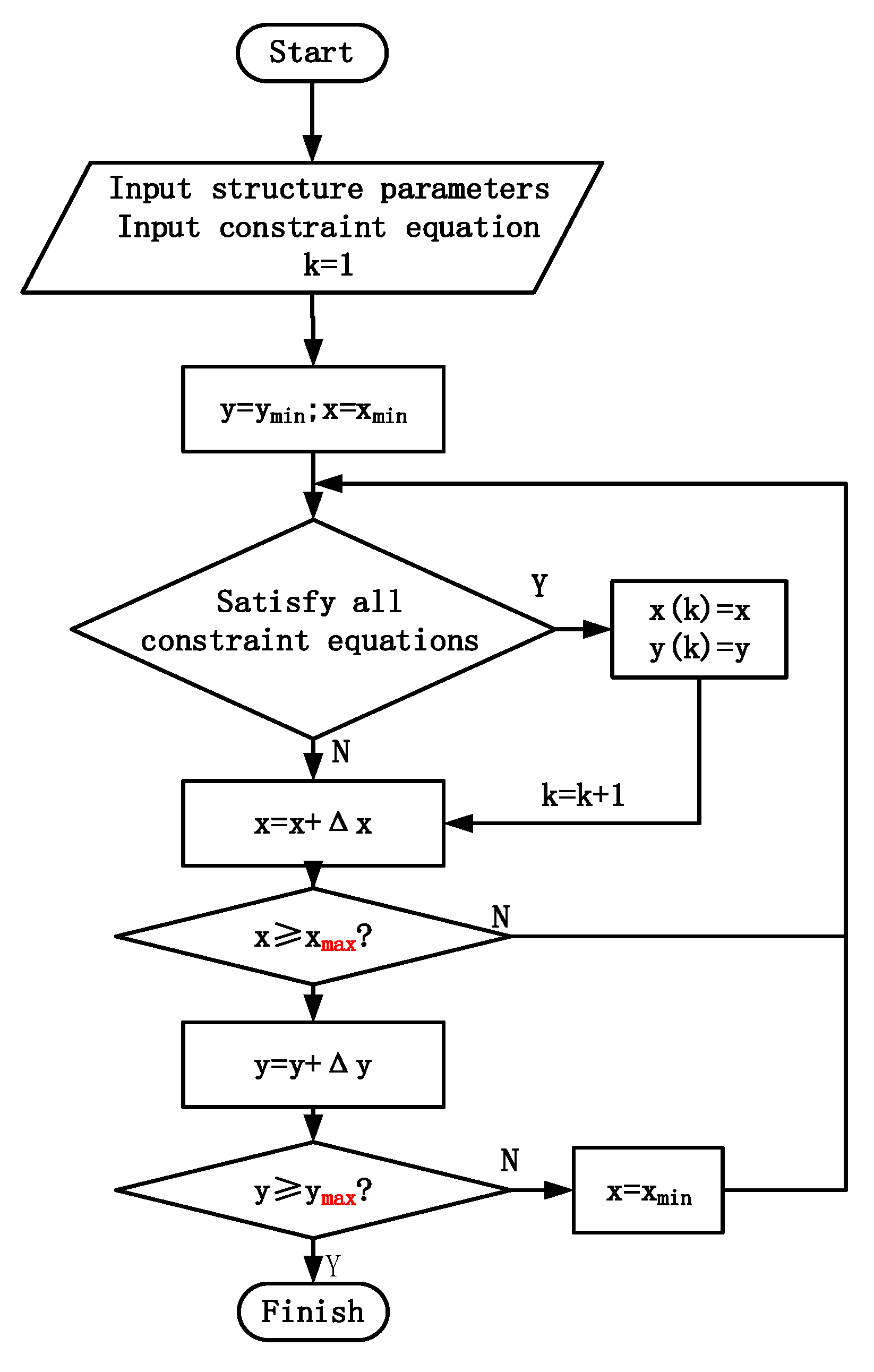
The MATLAB software is programmed to calculate the point set in the space where the constraints are met, using a numerical method to describe the workspace V Π of the MES working device. Depending on the number of points in the area, the size of the location workspace can be calculated as follows:
V Π = length ( X ) Δ x Δ y
where length ( X ) : the number of points; Δ x Δ y : step size of variables.
Based on the position equation of the mechanism, all points satisfying the constraint conditions are solved to form the workspace of the mechanism. The size of its workspace area can be expressed as the following multivariate function: β 2 .
V Π = f ( L 0 , l 1 , l 3 , l 4 , l A P , l B P , β 1 , β 2 )
Through changing the value of the design variable multiple times while meeting the above constraints, all points that satisfy the constraints can be searched out. These sets of points, which satisfy the conditions, make up the workspace of the MES working devices, and the workspace solution flow is shown in Figure 9.
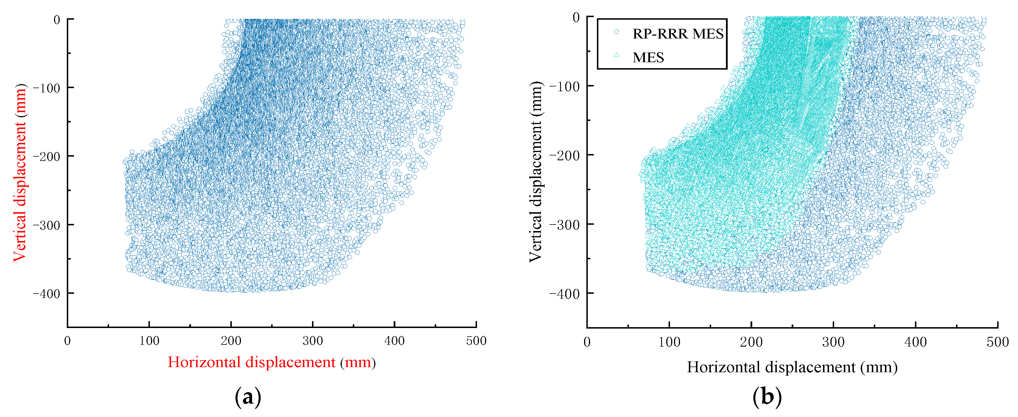
Similarly, the kinematic equations of the MES working devices can be solved based on the closed-loop vector equation method. Using the same algorithm to solve its workspace, and the comparative analysis of the workspace of the RP-RRR-type MES working devices, with the results shown in Figure 10.
As shown in Figure 10, the RP-RRR-type MES working device can be moved farther in the x-axis direction with the same rod parameters and has a larger reachable working space range in which there are good prospects for application.

4. Optimization of Rod Parameters

4.1. Influence of Rod Size Parameters on the Working Space

The variation of the rod parameters of the mechanism has a large impact on its working performance. Based on the workspace range of RP-RRR-type MES, the influence of bar parameters on the workspace was analyzed by univariate method. The following range of variation of rod parameters was set:
230   mm L 0 350   mm 20   mm l 1 50   mm 220   mm l 3 320   mm 220   mm l 4 320   mm
The influence of the value of the rods L 0 , l 1 , l 2 and l 3 on the workspace is solved respectively, as shown in Figure 11. The x-axis is the length of the rod, and the y-axis is the proportional coefficient of the optimized workspace and the pre-optimized workspace.

4.2. Optimization Model for Working Devices

Based on the results of the previous analysis, the constraint range of the rod parameters of the mining shovel working device is given as follows:
250   mm L 0 350   mm 20   mm l 1 30   mm 240   m m l 3 300   m m 240   m m l 4 300   m m
The optimization model of MES working devices is set as follows:
f i n d   L 0   l 1   l 3   l 4 min   f = 1 V s . t .   g 1 = θ min θ i 0 g 2 = θ i θ max 0 g 3 = l min l i 0 g 4 = l i - l max 0 g 5 = D i D 0 i = 1 , 2 , 3

4.3. Optimization Analysis of RP-RRR-Type MES Working Devices

Take the workspace V Π of the RP-RRR-type MES working devices as the optimization objective function. According to the value of the structural parameters of the MES working device described in Table 4, set the parameters l A P , l B P , β 1 , etc. based on the genetic algorithm to optimize and analyze the rod size parameters of the work device; the optimization parameters were set as follows: population K = 30, crossover probability Pc = 0.8, variation probability Pm = 0.05 and termination evolution generation G = 600. The table following, Table 5, is the 10 sets of optimization results of the workspace optimization of the MES working device.
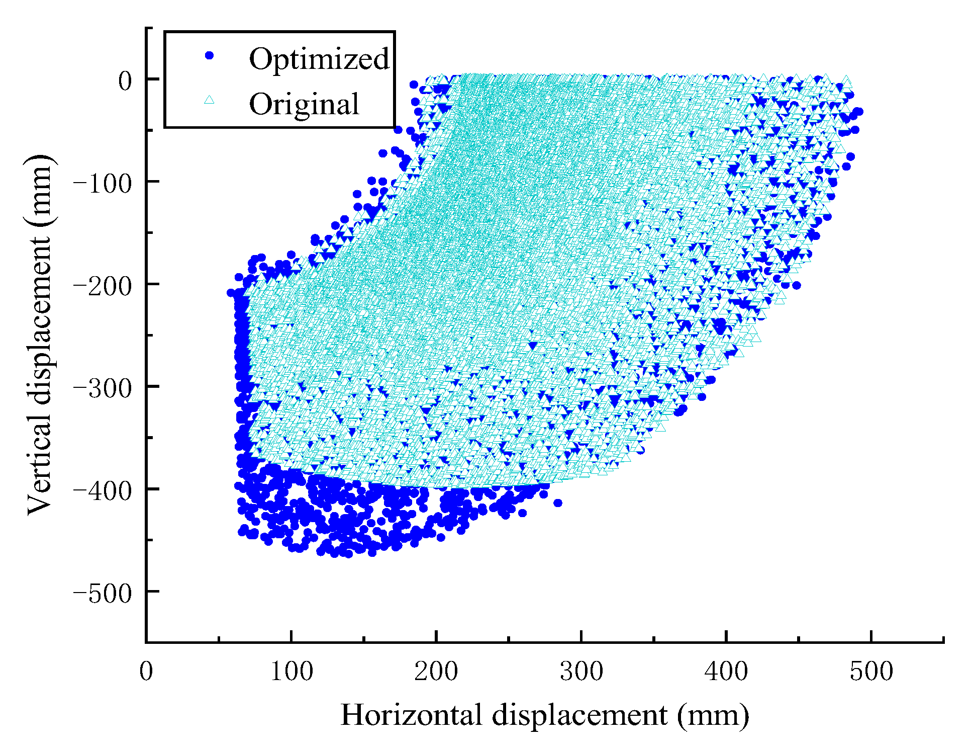
According to the optimization results shown in Table 4, the data of the sixth group of rod parameters is selected as the optimal MES working device structure parameters. The comparison diagram of its working space range before and after optimization is shown in Figure 12, below.
The results show that the optimized MES working device can move further in the y-axis direction and has a larger working space range, which is increased by 13.4789%.

5. Simulation Analysis and Experimental Verification

5.1. EDEM and RecurDyn Bidirectional Coupling Simulation Analysis

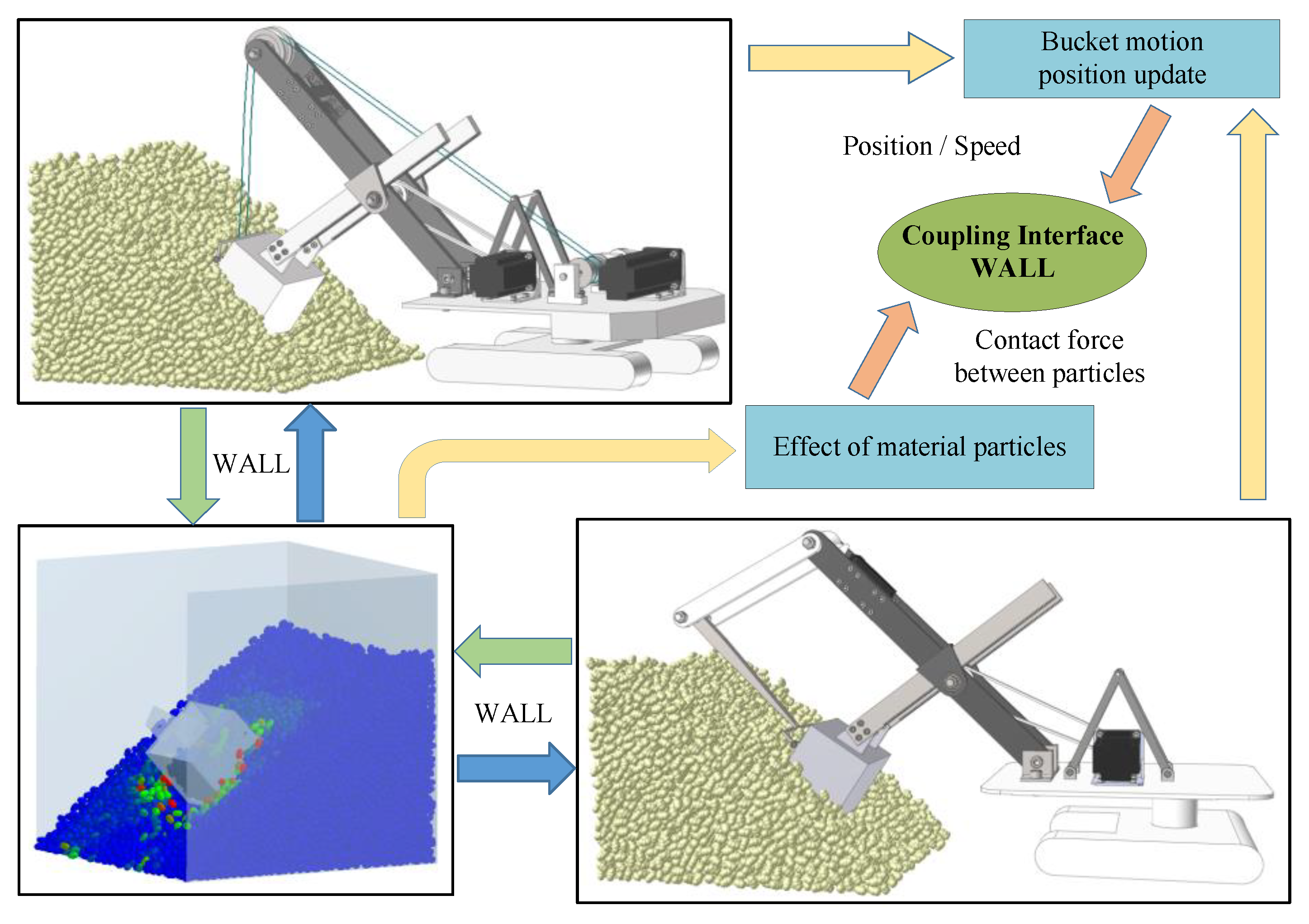
In the actual excavation work, the stacking angle of the material is complex and variable. In order to facilitate the analysis and research, the material stacking surface is simplified to a smooth plane with a slope of 40º. The discrete element model of the material is established in EDEM, and the material properties and contact parameters between the materials are set in reference [24]. The simulation analysis of the mining process of the MES working devices is completed by EDEM-RecurDyn bidirectional coupling simulation, as shown in Figure 13.

5.2. Experimental Verification of the MES Working Device

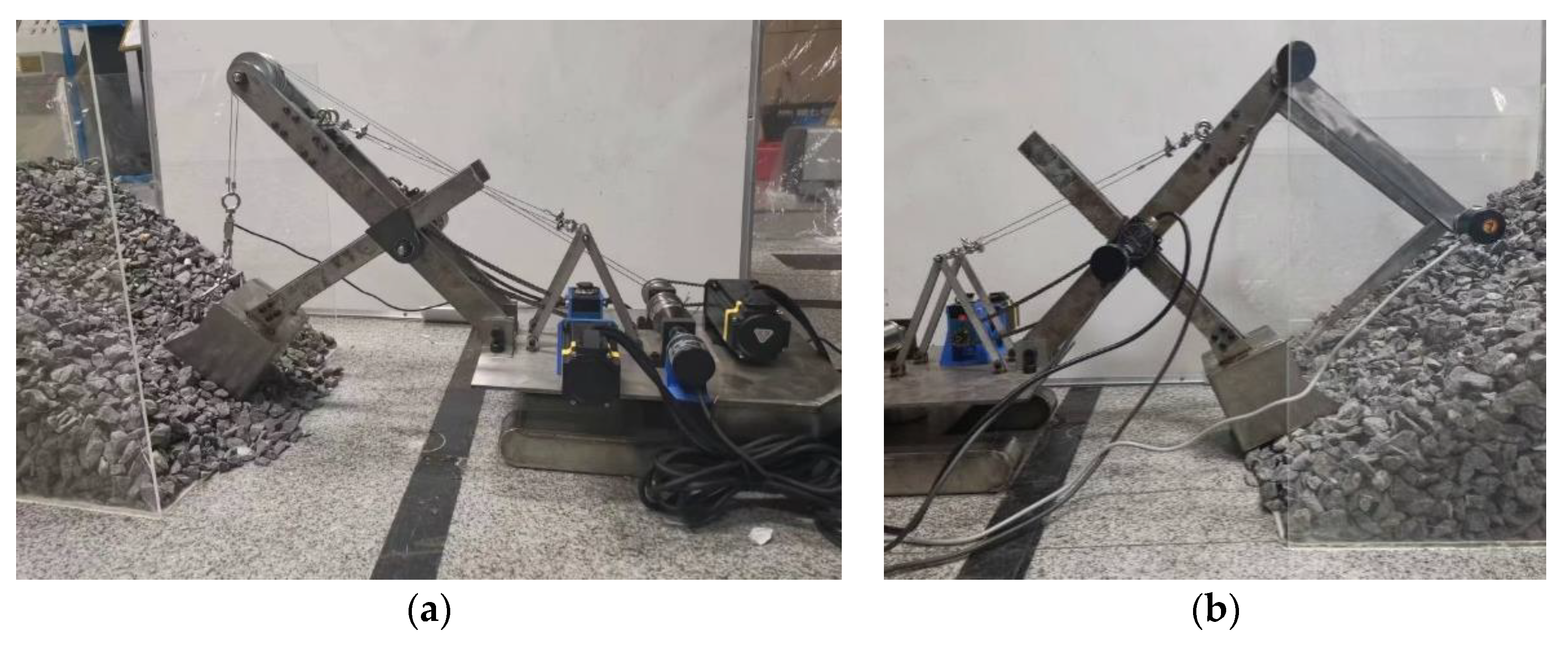
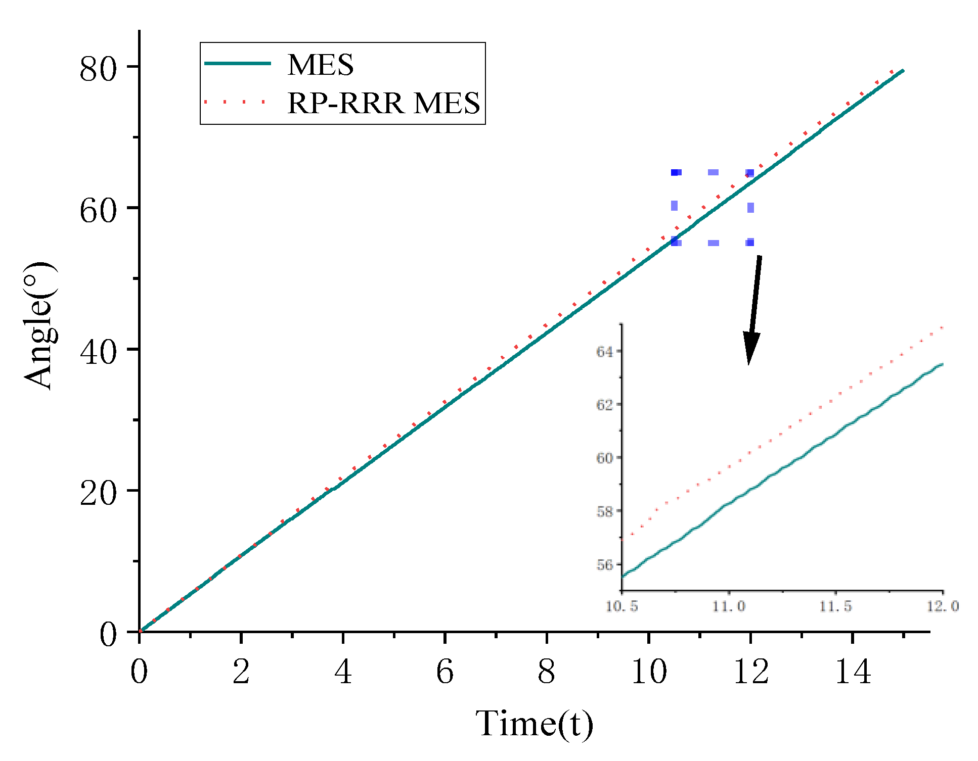
In order to facilitate analysis and experimental verification, based on the similarity theory [25,26], the MES prototype platforms were built and used. As shown in Figure 14, based on a scale ratio of 1:30, two kinds of mining electric shovel working device prototype platform are built, and the pile surface of the material is set to 40°. Given the logarithmic spiral digging trajectory, the kinematics equation is used to solve the input of the working device. According to the results of the equation, the driving parameters of the motor are set. The measured angle of the stick is shown in Figure 15 below.
Under the same test conditions, the average value of the five excavation results is taken as the test result, the excavation quality inside the bucket of the working device was analyzed after the excavation was completed, and the simulation analysis results were compared and verified, as shown in Table 6.
It can be seen from Table 6 that the test results of the two MES working devices are basically consistent with the simulation results, and the excavation quality difference of the two MES working devices are 2.02% and 2.20%, respectively. The results verify the results of the bidirectional coupling simulation of the working device, and also verify the feasibility of the RP-RRR-type MES working devices.

6. Conclusions

(1) For the first time, the screw theory is applied to analyze the problem of configuration synthesis of MES device. Based on the constrained synthesis method of screw theory, the working device of the MES is analyzed. By synthesizing and optimizing the branched chain structure, 100 kinds of MES working device synthesis scheme I, and 14 kinds of MES working device synthesis scheme II were obtained.
(2) The position equation of the RP-RRR-type MES working device is solved by the closed-loop vector equations, and the correctness of the kinematics equation is verified by simulation analysis. The numerical method is used to calculate the point set in the space that satisfies the constraint conditions, which is used to describe the workspace of the MES working device.
(3) The influence of bar parameters on the working space is analyzed. The genetic algorithm is used to optimize the parameters, and the working space of the optimized working device is increased by 13.4789%. The scale model test bench of MES and RP-RRR-type MES is built, and the excavation test is carried out. By comparing the experimental results with the simulation results, the feasibility of the RP-RRR MES working device is verified, and the effectiveness of the comprehensive method is proved.
This research can provide new ideas and methods for the mechanism design and innovation of excavators, and also provide a theoretical basis for the intelligent and unmanned development of the mechanism, which has certain feasibility and applicability. In subsequent research, the energy consumption of RP-RRR-type MES working devices can be further analyzed. On this basis, combined with the motion/force transmissibility, the high-quality workspace of the MES mechanism can be further analyzed and optimized to better meet the actual use requirements.

Author Contributions

Writing—Original draft, C.G.; Writing—review and editing, J.W.; Conceptualization, C.G. and Y.F.; Methodology, C.G. and Y.W.; Data curation, X.W.; Funding acquisition, J.W. All authors have read and agreed to the published version of the manuscript.

Funding

This research was funded by National Natural Science Foundation of China (Project No. U21A20125), Natural Science Foundation of Shanxi Province (Project No. 20210302124060), and the Postgraduate Innovation Project of Shanxi Province (Project No. 2022Y206).

Data Availability Statement

Not applicable.

Acknowledgments

The authors would like to thank Taiyuan University of Technology for the support. The authors are sincerely grateful to the reviewers for their valuable review comments, which substantially improved the paper.

Conflicts of Interest

The authors declare no conflict of interest.

References

  1. Wei, B.; Gao, F.; Chen, J.; He, J.; Wu, S.; Song, Q. Mechanics performance of three-degree-of-freedom excavating mechanism of an electric shovel. Proc. Inst. Mech. Eng. Part C J. Mech. Eng. Sci. 2011, 225, 1443–1457. [Google Scholar] [CrossRef]
  2. Hervé, J. The Lie group of rigid body displacements, a fundamental tool for mechanism design. Mech. Mach. Theory 1999, 34, 719–730. [Google Scholar] [CrossRef]
  3. Li, Q.; Huang, Z.; Hervé, J. Type synthesis of 3R2T 5-DOF parallel mechanisms using the lie group of displacements. IEEE Trans. Rob. Autom. 2004, 20, 173–180. [Google Scholar] [CrossRef]
  4. Meng, J.; Liu, G.F.; Li, Z.X. A geometric theory for analysis and synthesis of Sub-6 DOF parallel manipulators. IEEE Trans. Rob. 2007, 23, 625–649. [Google Scholar] [CrossRef]
  5. Gogu, G. Structural Synthesis of Parallel Robots: Part 2: Translational Topologies with Two and Three Degrees of Freedom; Springer: Dordrecht, The Netherlands, 2009. [Google Scholar]
  6. Gogu, G. Structural Synthesis of Parallel Robots: Part 3: Topologies with Planar Motion of the Moving Platform; Springer: Dordrecht, The Netherlands, 2010. [Google Scholar]
  7. Gogu, G. Structural Synthesis of Parallel Robots: Part 4: Other Topologies with Two and Three Degrees of Freedom; Springer: Dordrecht, The Netherlands, 2012. [Google Scholar]
  8. Yang, T.; Liu, A.; Shen, H.; Hang, L.; Ge, Q. Composition principle based on single-open-chain unit for general spatial mechanisms and its application—In conjunction with a review of development of mechanism composition principles. ASME J. Mech. Robot. 2018, 10, 051005. [Google Scholar] [CrossRef]
  9. Kong, X.W.; Gosselin, C.M. Type synthesis of 3-DOF translational parallel manipulators based on screw theory. J. Mech. Des. 2004, 126, 83–92. [Google Scholar] [CrossRef]
  10. Kong, X.W.; Gosselin, C.M. Type synthesis of 4-DOF SP-equivalent parallel manipulators: A virtual chain approach. Mech. Mach. Theory 2006, 41, 1306–1319. [Google Scholar] [CrossRef]
  11. Han, B.; Xu, Y.; Yao, J.; Zheng, D.; Guo, X.; Zhao, Y. Configuration synthesis of hoop truss deployable mechanisms for space antenna based on screw theory. AIP Adv. 2019, 9, 085201. [Google Scholar] [CrossRef] [Green Version]
  12. Zhao, Y.; Yuan, F.; Chen, C.; Jin, L.; Li, J.; Zhang, X.; Lu, X. Inverse kinematics and trajectory Planning for a Hyper-redundant bionic Trunk-like robot. Int. J. Robotics Autom. 2020, 35, 229–241. [Google Scholar] [CrossRef]
  13. Wang, Y.; Lyu, C.; Liu, J. Kinematic Analysis and Verification of a New 5-DOF Parallel Mechanism. Appl. Sci. 2021, 11, 8157. [Google Scholar] [CrossRef]
  14. Chen, M.; Zhang, Q.; Ge, Y.F.; Qin, X.R.; Sun, Y.T. Dynamic analysis of an over-constrained parallel mechanism with the principle of virtual work. Math. Comput. Model. Dyn. Syst. 2021, 27, 347–372. [Google Scholar] [CrossRef]
  15. Kang, H.; Deng, Z.; Luo, L. Workspace analysis of 6-PTRT parallel robot. J. Liaoning Univ. Petrochem. Technol. 2019, 39, 82–89. [Google Scholar]
  16. Hao, F.; Merlet, J.P. Multi-criteria optimal design of parallel manipulators based on interval analysis. Mech. Mach. Theory 2005, 40, 157–171. [Google Scholar] [CrossRef]
  17. Lei, J.; Wang, J. Orientation Workspace Analysis and Parameter Optimization of 3-RRPS Parallel Robot for Pelvic Fracture Reduction. J. Mech. Robot. 2023, 15, 051003. [Google Scholar] [CrossRef]
  18. Cao, Y.; Lu, K.; Li, X.; Zhang, Y. Accurate Numerical Methods for Computing 2D and 3D Robot Workspace. Int. J. Adv. Robot. Syst. 2011, 8, 76. [Google Scholar] [CrossRef] [Green Version]
  19. Behera, L.; Rybak, L.; Malyshev, D.; Khalapyan, S. Numerical simulation of the workspace of robots with moving bases in the multi-agent system. Procedia Comput. Sci. 2021, 186, 431–439. [Google Scholar] [CrossRef]
  20. Wang, D.; Zhang, J.; Guo, H.; Liu, R.; Kou, Z. Design of a 2T1R-Type Parallel Mechanism: Performance Analysis and Size Optimization. Actuators 2022, 11, 262. [Google Scholar] [CrossRef]
  21. Zhu, S.; Huang, Z. Eighteen fully symmetrical 5-DoF 3R2T parallel manipulators with better actuating modes. Inter-Natl. J. Adv. Manuf. Technol. 2007, 34, 406–412. [Google Scholar] [CrossRef]
  22. Chen, C.; Li, T.; Tang, Y. Configuration Synthesis of Generalized Mechanism Based on Screw Theory. Iran. J. Sci. Technol. Trans. Mech. Eng. 2019, 43, 1013–1021. [Google Scholar] [CrossRef]
  23. Li, Q.; Huang, Z. Mobility analysis of lower-mobility parallel manipulators based on screw theory. In Proceedings of the 2003 IEEE International Conference on Robotics and Automation, Taipei, Taiwan, 14–19 September 2003; Volume 1, pp. 1179–1184. [Google Scholar]
  24. Feng, Y.; Wu, J.; Guo, C.; Lin, B. Numerical simulation and experiment on excavating resistance of an electric cable shovel based on edem-recurdyn bidirectional coupling. Machines 2022, 10, 1203. [Google Scholar] [CrossRef]
  25. Fan, R.; Li, Y.; Yang, L. Trajectory Planning Based on Minimum Input Energy for the Electro-Hydraulic Cable Shovel. In Proceedings of the 2020 IEEE/ASME International Conference on Advanced Intelligent Mechatronics (AIM), Boston, MA, USA, 6–9 July 2020. [Google Scholar]
  26. Fan, R.; Li, Y.; Yang, L. Multiobjective trajectory optimization of intelligent electro-hydraulic shovel. Front. Mech. Eng. 2022, 17, 50. [Google Scholar] [CrossRef]
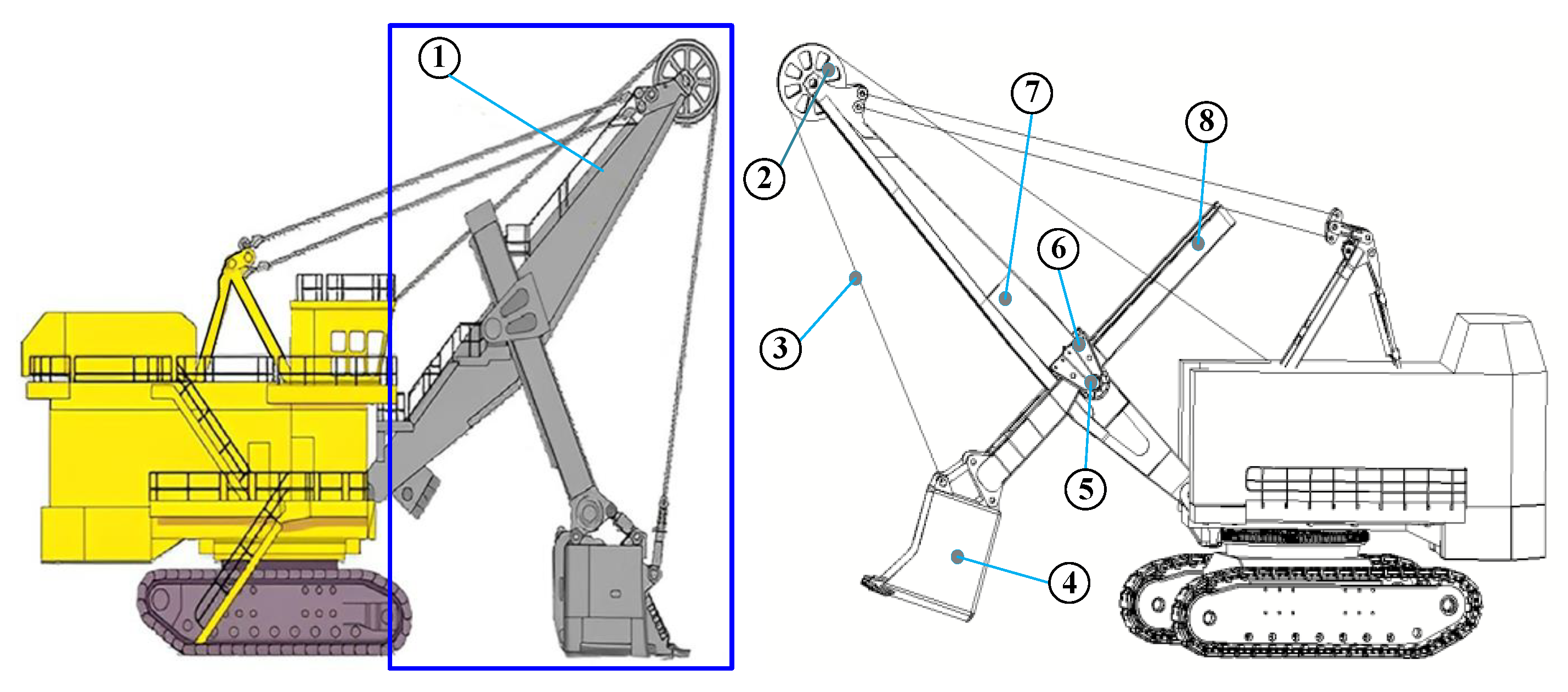
Figure 1. Structural components of MES working devices: ① the working device of the MES, ② sheave pulley, ③ lifting wire rope, ④ bucket, ⑤ push shaft, ⑥ saddle, ⑦ boom and ⑧ bucket rod.
Actuators 12 00317 g001
Figure 2. Sketch of the mechanism of the MES, from a working device.
Actuators 12 00317 g002
Figure 3. MES working device synthesis scheme I.
Actuators 12 00317 g003
Figure 4. MES working device synthesis scheme II.
Actuators 12 00317 g004
Figure 5. RP-RRR-type mining shovel design scheme.
Actuators 12 00317 g005
Figure 6. The mathematical model of RP-RRR-type MES working devices.
Actuators 12 00317 g006
Figure 7. Comparison of position solution theory and simulation results: (a) the length of l2; and (b) the angle of rotation of θ2.
Actuators 12 00317 g007
Figure 8. Comparison of theoretical and simulation results for rod input velocity: (a) the elongation speed of l2; and (b) the angle speed of rotation of θ2.
Actuators 12 00317 g008
Figure 9. Workspace-solving flow chart.
Actuators 12 00317 g009
Figure 10. Comparison of the working space of the work device: (a) the workspace of RP-RRR-type MES working device; and (b) the workspace comparison diagram.
Actuators 12 00317 g010
Figure 11. Influence of rod parameters on the working space: (a) L 0 ; (b) l 1 ; (c) l 2 ; and (d) l 3 .
Actuators 12 00317 g011
Figure 12. Comparison of the working space of the MES working devices.
Actuators 12 00317 g012
Figure 13. EDEM-RecurDyn bidirectional coupling simulation.
Actuators 12 00317 g013
Figure 14. Prototype platform of working device: (a) MES; and (b) RP-RRR-type MES.
Actuators 12 00317 g014
Figure 15. Turning angle of the bucket rod.
Actuators 12 00317 g015
Table 1. Kinematic screw and constraint screw of the working device.
Kinematic ScrewConstraint Screw
Subchain I S 11 = 1 , 0 , 0 , 0 , 0 , 0 S 12 = 0 , 0 , 0 , 0 , a 1 , b 1 S 11 r = 1 , 0 , 0 , 0 , 0 , 0 S 12 r = 0 , 0 , 0 , 0 , 1 , 0 S 13 r = 0 , 0 , 0 , 0 , 0 , 1 S 14 r = 0 , b 1 , a 1 , 0 , 0 , 0
Subchain II S 21 = 1 , 0 , 0 , 0 , a 2 , b 2 S 22 = 0 , 0 , 0 , 0 , a 3 , b 3 S 23 = 1 , 0 , 0 , 0 , a 4 , b 4 S 21 r = 1 , 0 , 0 , 0 , 0 , 0 S 22 r = 0 , 0 , 0 , 0 , 1 , 0 S 23 r = 0 , 0 , 0 , 0 , 0 , 1
Table 2. The common 6-DOF active branched chain structure.
Structure Type6-DOF Branched Chain Structure
IRUS, RSU, PUS, PSU
SPU, UPS, SRU, SUR
URS, USR, SUP, USP
IIRSS, PSS, SPS
SRS, SSR, SSP
IIICRS, CPS, UCU, CUU
CUS, CSU, UCS, SCU
CSS, SCS, RCS, SCR
PCS, SCH, CSR, CSP
Table 3. Branched-chain-structure type of synthesis scheme II.
The Structure Type of Branch IThe Structure Type of Branch II
RPRSR, RPS, PPS
RCR, PCR
RRR, RRP, PRR
SPRCR, PCR
RRR, RRP, RPR, PRR
Table 5. Optimization results for RP-RRR-type MES working devices.
No.Design VariablesOptimization Results
L0l1l3l4
1256.688127.6433247.2907277.1148−0.8379%
2344.943226.8493268.3057282.5948−5.7994%
3343.402622.4208244.9275284.2629−6.1360%
4299.790428.9187248.2934250.25383.7150%
5334.350227.2155245.0065290.1873−1.1705%
6262.702124.8517294.0936291.291113.4789%
7258.930924.0451254.7247243.3277−1.7839%
8301.495622.4725284.6440297.42113.2607%
9295.218226.8182260.2839274.5947−0.0586%
10297.388325.3067288.2746267.99161.8651%
Table 6. Comparison between simulation data and experimental data.
Simulation DataExperimental DataExcavation Quality Difference
MES working device1.815 kg1.779 kg2.02%
RP-RRR-type MES device1.808 kg1.769 kg2.20%
Disclaimer/Publisher’s Note: The statements, opinions and data contained in all publications are solely those of the individual author(s) and contributor(s) and not of MDPI and/or the editor(s). MDPI and/or the editor(s) disclaim responsibility for any injury to people or property resulting from any ideas, methods, instructions or products referred to in the content.