Article

The Impact Modeling and Experimental Verification of a Launch Vehicle with Crushing-Type Landing Gear

1
State Key Laboratory of Robotics and System, Harbin Institute of Technology, Harbin 150001, China
2
Wuhan Second Ship Design and Research Institute, Wuhan 430205, China
*
Author to whom correspondence should be addressed.
Actuators 2023, 12(8), 307; https://doi.org/10.3390/act12080307
Submission received: 3 July 2023 / Revised: 21 July 2023 / Accepted: 24 July 2023 / Published: 26 July 2023
(This article belongs to the Section Aircraft Actuators)

Abstract

:
In order to investigate the landing process of a vertical landing reusable vehicle, a dynamic model with a complex nonlinear dissipative element is established based on the discrete impulse step approach, which includes a three-dimensional multi-impact model considering friction and material compliance, and a multistage aluminum honeycomb theoretical model. The normal two-stiffness spring model is adopted in the foot–ground impact model, two motion patterns (stick and slip) are considered on the tangential plane and the structural changes caused by buffering behavior are included, and the energy conversion during the impact follows the law of conservation of energy. The state transition method is used to solve the dynamic stability convergence problem of the vehicle under the coupling effect of impact and buffering deformation in the primary impulse space. Landing experiments on a scaled physical reusable vehicle prototype are conducted to demonstrate that the theoretical results exhibit good agreement with the experimental data.

1. Introduction

In the field of engineering, when a mechanical system collides during movement, substantial impact energy will be generated instantaneously. If there is no material or device in the system that can absorb the impact energy, the internal structure of the mechanical system will be subjected to serious deformation and even fracture [1,2]. Therefore, a buffer is often added to a mechanical system that may encounter collisions. When the impact occurs, the buffer device adopts its own specific kind of deformation to absorb the impact energy effectively to protect the mechanical system. In the literature [3], a lander without buffering material was designed by imitating the landing process of a locust through its legs; during this landing, the impact energy is transformed into viscoelastic deformation and leg structure deformation due to viscoelastic feet and a joint torsion spring. In Reference [4], a six-legged lunar lander that can be repeatedly used was designed to absorb impact energy via structural deformation during landing, and its effectiveness was verified through simulations and experiments. To sum up, large deformation and a structural configuration change will invariably occur when multibody systems encounter impact.
The landing process of a vehicle is a complex dynamics process influenced by many factors [5,6,7]. Among them, the structural change of the system caused by buffering has an important impact on the collision behavior. References [8,9] compared the buffering effect of different landing structures, indicating that the different structural deformation modes caused by buffering lead to varying landing results. A discrete element method (DEM)–finite element method (FEM)–multibody dynamics (MBD) model was proposed in Reference [10], the dynamic landing process of a lunar lander considering the characteristics of lunar soil was simulated, and the influence mechanism of key parameters on the landing process was analyzed. In the literature [11], two landing modes, shutdown-before-touchdown and shutdown-at-touchdown, were proposed in consideration of the two conditions of the Mars lander’s engines during landing, and the landing stability and impact on the collision under these two modes were analyzed. Therefore, considering the coupling effect of collision and buffering is an important factor to simulate the landing process of a vehicle with the inverted-triangle landing gear [12].
As for impact, in correlational studies of landing, even in the engineering field, there are usually two modeling approaches: (1) The discrete approach, taking the energy and velocity before and after the impact as objectives, and assuming that the position and structure of the impact body remain unchanged during the impact [13,14]. However, this modeling approach is incapable of simulating cases when series of impacts happen. (2) The continuous approach, which establishes the force–displacement relationship between two colliding objects [15,16,17,18,19] to simulate the complete impact process, which is widely used. This method allows for multiple impacts, and can provide the complete impact force history, but cannot guarantee the energy conservation of the impact process.
The buffering material used in the four-legged landing gear of vehicles is two-stage aluminum honeycomb. Aluminum honeycomb material is not only environmentally friendly, low-cost, and easy to shape, but also has the advantages of light weight, high strength, good buffering performance [1,20,21], high surface flatness, etc.; these characteristics satisfy all the requirements for the buffering material of the legged landing gear of a vehicle [6,22]. In the literature [23], scholars established a landing process model of the lunar lander with carbon nanopaper and two-stage aluminum honeycomb as the buffer materials, respectively, and compared the buffering characteristics of the two materials under three extreme landing conditions. Jinhua Zhou [24] and other scholars carried out a parameter optimization design of an aluminum honeycomb buffer, obtaining better landing performance with the lander. In order to optimize the center overload of the lunar lander with inverted-triangle landing gear, scholars proposed a multiobjective optimization method to optimize the material and structural parameters of the three-stage aluminum honeycomb buffer [25]. Based on the above, two-stage aluminum honeycomb can be used as the buffering material in the landing process of a vehicle with legged landing gear.
In this paper, due to the intercoupling characteristics of multiple impacts and large buffering deformation during the landing of a vertical landing reusable vehicle, the landing dynamics process can be equivalent to the convergence process of a complex discrete nonlinear system, which consists of multiple states, each of which can be transformed into the other under certain dynamic conditions. Then, in each state of the discrete system, according to the coupling relationship between the impact and buffer behavior, the primary impulse is selected, and the relationship network between the remaining impulses and the primary impulse is established, then substituted into the landing equations in a certain state; through the above steps, the complex coupling mechanism between the multi-impact process and the buffering process of the landing vehicle is simulated in the discrete impulse space with the hope that this modeling method can accurately predict the landing behavior of the vertical landing vehicle.

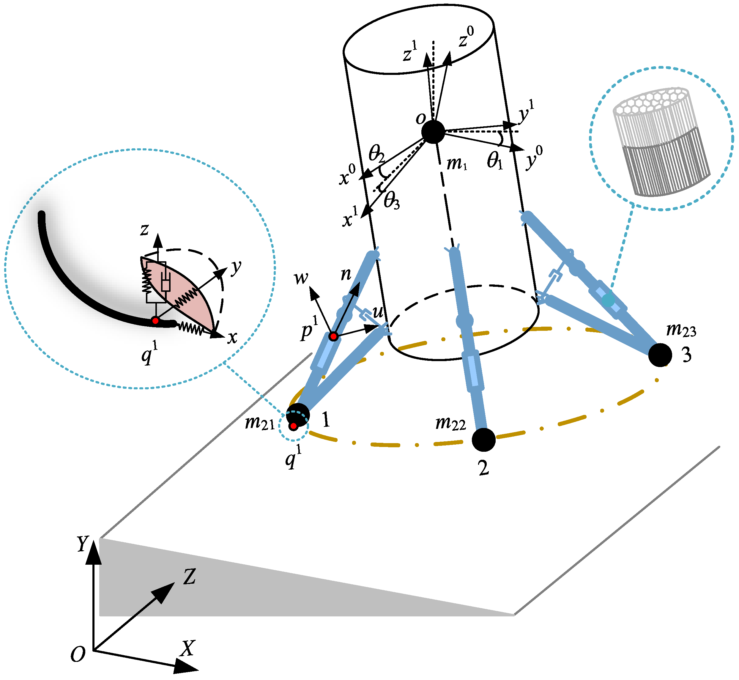
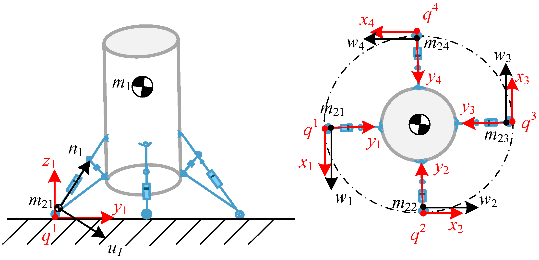
2. Landing Model of a Vehicle Considering the Impact–Buffering Coupling Effect

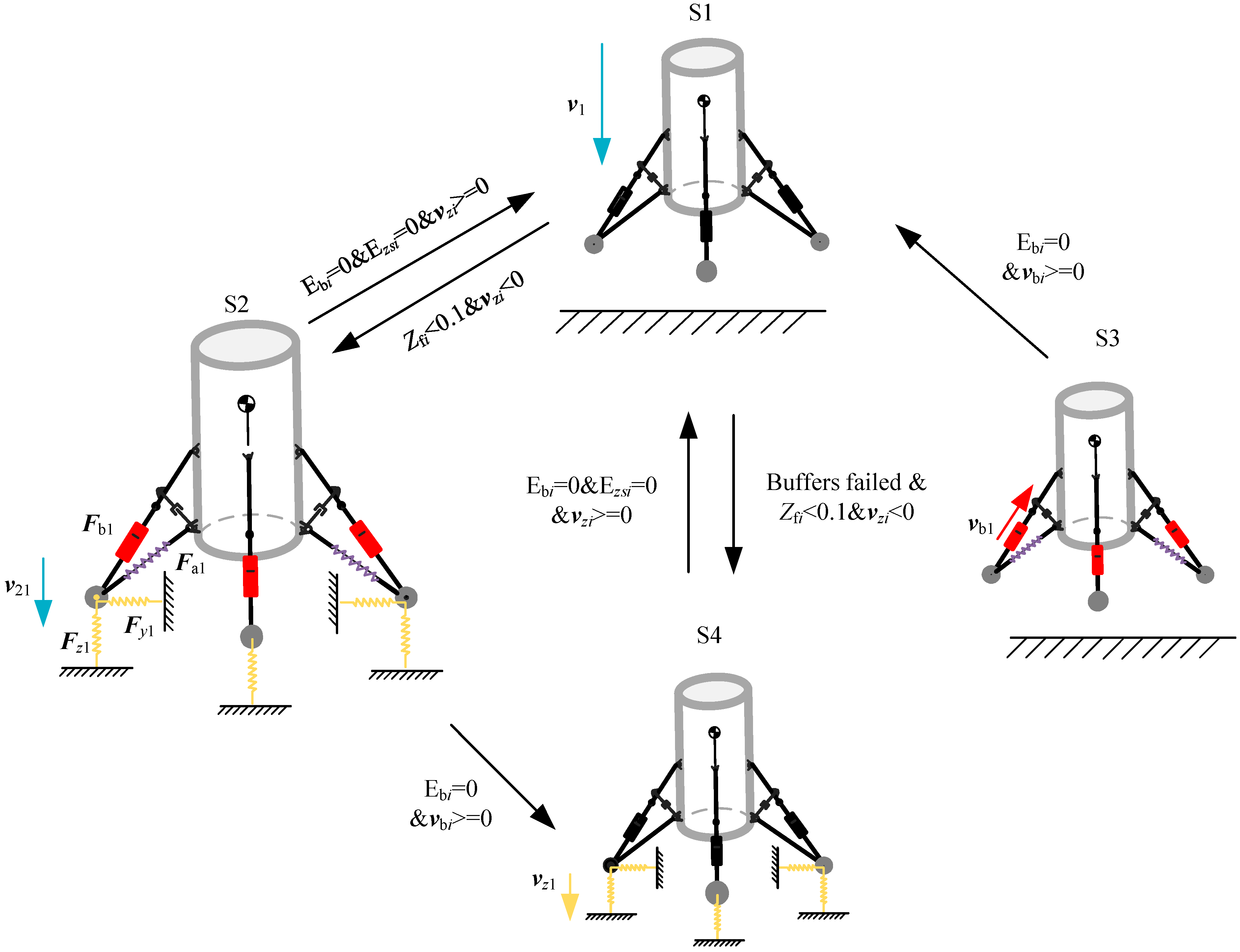
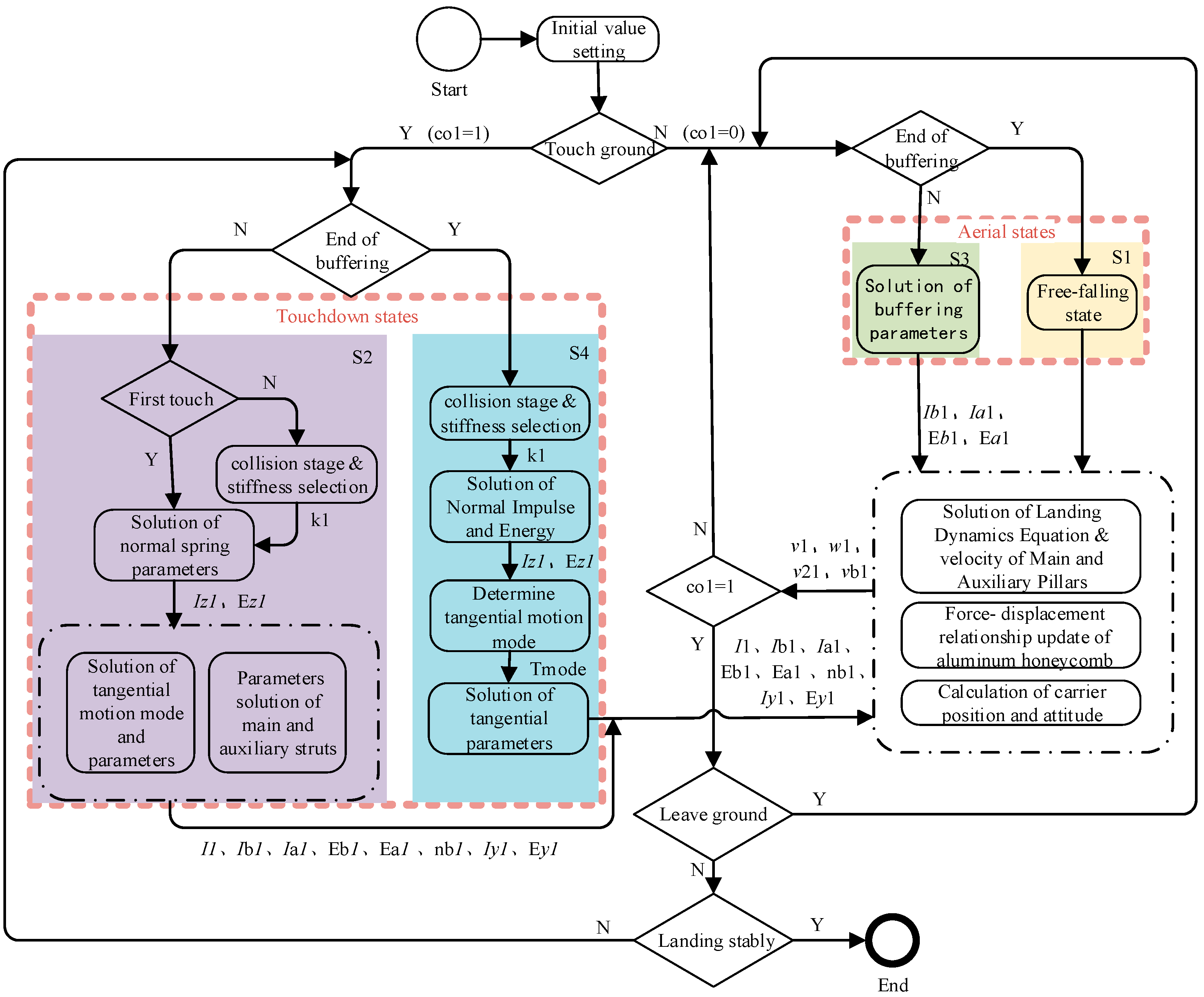
2.1. Vertical Landing Process of the Vehicle

The landing process of a vehicle with inverted-triangle landing gear involves the vehicle freefalling in the aerial state until the feet touch the ground, then entering the touchdown state until it lands stably or tips over. After the vehicle touches the ground, the foot of the landing gear may experience multiple impacts with the ground; during this period, the buffering behavior and the impact process will be coupled with each other and collectively affect the landing process of the vehicle. However, when the vehicle transfers from the touchdown state to the aerial state under certain conditions, at which time the feet of the landing gear will leave the ground, the buffering behavior may act solely on the nonlinear vehicle system. When the release of a small amount of elastic energy of the buffer ends, it may enter the state of freefalling again or return to the state of touchdown again under certain conditions. In addition, in the process of touching the ground, the structure damping of the landing gear will absorb some of the impact energy, and finally, the entire vehicle system will converge through damped periodic oscillation; in other words, the vehicle finally lands stably.
In establishing an impact–buffering multibody system model for a vertical landing vehicle, inverted-triangle landing gear was used. First of all, the vehicle was divided into two parts: the mass of the main body, the upper parts of the main pillars, and the auxiliary pillars are concentrated in the center of mass of the vehicle, while the mass of the lower part of the main pillar to the foot is on the center of mass of the foot, as shown in Figure 1. Furthermore, the force exerted on the auxiliary strut of the inverted-triangle landing gear will also impose constraints in the collision–buffering coupling process; hence, the auxiliary strut was simplified into a massless spring element.
Based on the landing process state machine, the vehicle can be considered as a nonlinear system in the states where the buffering behavior is activated, while in the remaining states, the vehicle can be regarded as a rigid body system without structural deformation. Transitions between different states can occur under specific dynamic conditions, forming a complex nonlinear dissipative system within the discrete impulse space, as illustrated in Figure 2. The behavior of the system will vary with the system parameters and initial conditions.
The meanings of the variables of Figure 2 are as follows:
Ebi and Ezsi—the elastic energy of the buffer in the main pillar of leg I and the elastic energy of the normal spring of the foot–ground impact I, respectively.
vzi and vbi—the normal velocity of the foot–ground impact I and the buffering velocity of the main pillar of leg i, respectively.
v1 and v21—the velocity of the main body and foot 1, respectively.
Zfi—the normal displacement of the foot i.
Fb1, Fa1, Fy1, and Fz1—the force of main pillar 1, auxiliary pillar 1, and the y and z spring of foot–ground impact 1.
The impulse space dynamics equations of the landing process of the reusable vehicle for all landing states (S1~S4) are as follows:
  • Nonlinear system states.
Main body:
m 1 v ˙ 1 = i = 1 4 F b i + i = 1 4 F a i + i = 1 4 F l i
Foot:
m 2 i v ˙ 2 i = F b i + F a i + F z i + F y i
  • Rigid-body system states.
m 1 v ˙ 1 = i = 1 4 F z i + i = 1 4 F y i
Among them,  F b i  represents the main pillar force,  F a i  is the auxiliary pillar force,  F l i  represents the lateral force exerted by the supporting leg on the main body,  F z i  is the normal force exerted on the foot’s center of mass by the ground, and  F y i  is the tangential force exerted on the foot’s centroid by the ground.

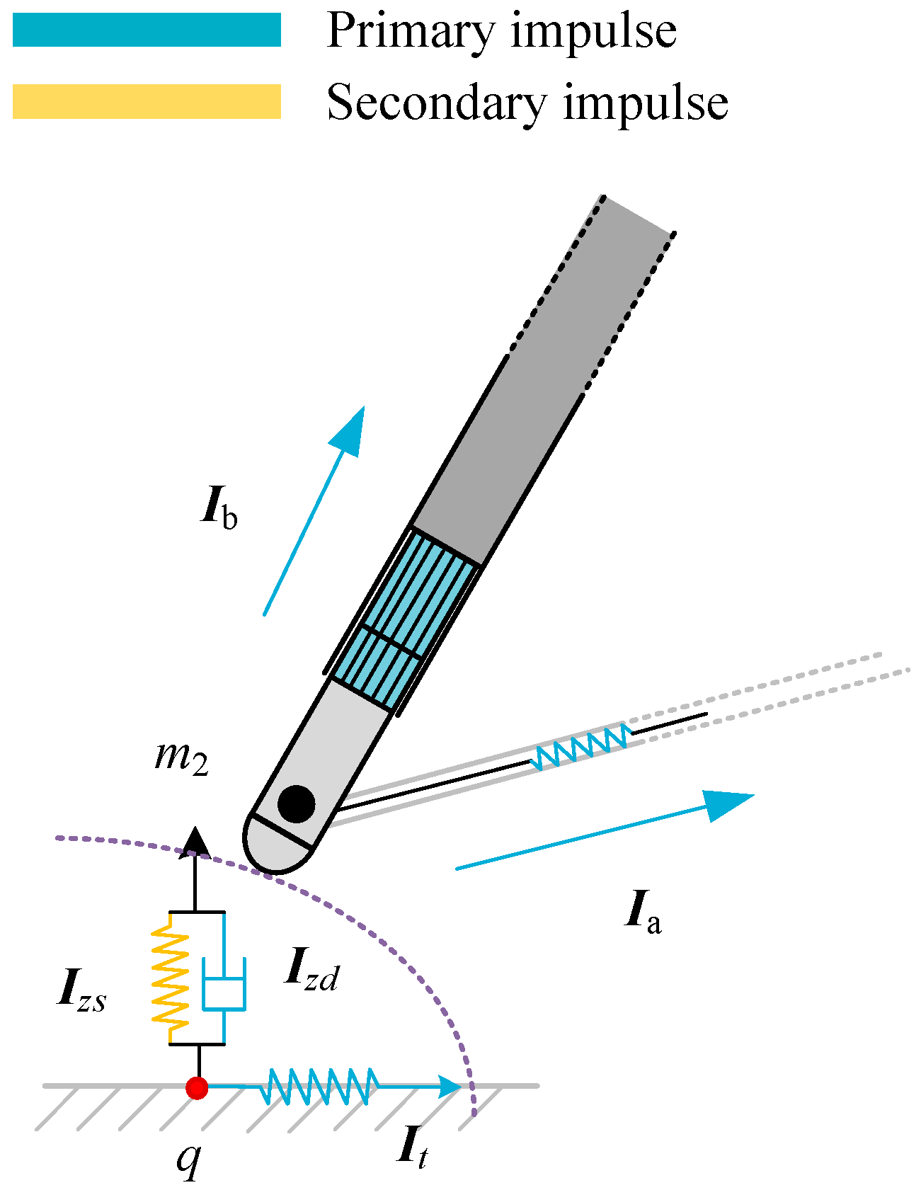
2.2. Three-Dimensional Impact Model with Friction

The impact between the foot and the ground during landing can be regarded as an elastic–plastic impact. As shown in the enlarged picture of the foot–ground impact in Figure 1, three mutually perpendicular springs (the normal direction is vertical upward) are set up at the impact point as the primary impact model [26,27]. The bi-stiffness spring is used to simulate the normal impact behavior between the foot and the ground, it has two states: compression and restitution, and the upward direction is set as the positive direction. At the end of compression, part of the impact energy will be consumed by plastic deformation; simultaneously, the spring stiffness increases by a fixed proportional coefficient, which is directly related to the coefficient of restitution and determined by the collision characteristics between the foot and the ground, which ensures the conservation of the energy during the impact. Additionally, the tangential plane springs can be either compressed or elongated, assuming that the direction of the virtual spring is positive when it is compressed.

2.2.1. Impulses of the Three-Dimensional Impact

Let  k tan  represent the stiffness of the tangent plane spring. In the coordinate of the impact point  q i  of foot i (Figure 3), the vertical upward direction is defined as the normal positive direction  z ; within the tangent plane, the  y  axis is in the plane composed by the two opposite legs, and the direction pointing to the main body is positive; and the direction of the  x  axis is perpendicular to the  y  axis in the tangent plane according to the right-hand rule.
Based on the above, the following expressions of the three-dimensional impact model are valid:
F z = k z 0 , F x = k tan x , F y = k tan y E z = 1 2 k z 2 , E x = 1 2 k tan x 2 , E y = 1 2 k tan y 2
when the normal spring impulse is selected to be the independent variable, the relationship between the other variables and the normal spring impulse is established for the iterative calculation of  d I z s .
E z s = d E z s d I z s = E ˙ z s I ˙ z s = k z z ˙ k z = z ˙ = v z , I ˙ z s = F z s = 2 k E z s ,   I ˙ x = F x = α 2 k tan E x ,   I ˙ y = F y = β 2 k tan E y
where  α  and  β  represent the x and y virtual spring states, respectively; their corresponding value is 1 when the spring is compressed. Otherwise, it will be set as −1.
z = 2 E z s k ,   x = 2 E x k tan ,   y = 2 E y k tan I x = I ˙ x I ˙ z s = α ζ E x E z s , I y = I ˙ y I ˙ z s = β ζ E y E z s
Among them,  ζ 2 = k tan k ; the subscript zs symbolizes the direction of  z  visual spring, and the subscript tan represents the tangential.
The total impulse of the impact of the foot and ground is  I = I x x + I y y + I z z .

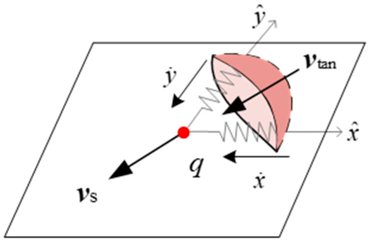
2.2.2. Tangential Motion Patterns

To determine whether the two perpendicular springs on the tangential plane are in the compressed or stretched state, it is necessary to obtain the real-time deformation of the two virtual springs:
x = 0 t x ˙ d t = 0 I z x ˙ d ( I z s F z s ) = 0 I z s x ˙ F z s d I z s = 0 I z s x ˙ ( 1 + χ z ˙ ) 2 k E z s d I z s ,   y = 0 I z y ˙ ( 1 + χ z ˙ ) 2 k E z s d I z
wherein  d t = d ( I z F z ) = 1 F z d ( I z )  holds under the assumption that Fz remains constant within every infinitesimal time period dt.
G x  and  G y  are brought in to represent the deformation of the spring to determine the displacement direction of the impact point on the tangent plane, that is, to determine whether it is in a state of compression or restitution:
G x = { 0 I z s x ˙ ( 1 + χ z ˙ ) E z s d I z s i f   I z s [ 0 , I c ] 0 I c x ˙ ( 1 + χ z ˙ ) E z s d I z s + I c I z s 1 γ x ˙ ( 1 + χ z ˙ ) E z s d I z s i f   I z s [ I c , I r ]
G y = { 0 I z s y ˙ ( 1 + χ z ˙ ) E z s d I z s i f   I z s [ 0 , I c ] 0 I c y ˙ ( 1 + χ z ˙ ) E z s d I z s + I c I z s 1 γ y ˙ ( 1 + χ z ˙ ) E z s d I z s i f   I z s [ I c , I r ]
where  0 I c x ˙ ( 1 + χ z ˙ ) E z s d I z s  and  0 I c y ˙ ( 1 + χ z ˙ ) E z s d I z s  represent the integral of the entire compression process of the x, y visual spring.
The relationship between  G x G y  and x, y is  G x = 2 k x , G y = 2 k y , and the relationship between the strain energy of the virtual springs is  E x = 1 2 k tan x 2 = G x 2 4 ζ 2 E y = 1 2 k tan y 2 = G y 2 4 ζ 2 . After obtaining  G x  and  G y , the tangential spring deformation, namely tangential material compliance, can be acquired. When the impact state of the normal virtual spring enters the restitution state, part of the foot–ground impact energy accumulated in compression will be dissipated as a form of plastic deformation, meanwhile the material will be hardened at the same time; in this case, the normal stiffness will increase from k to  k 1 γ .

2.2.3. Tangential Velocities

The tangential velocity refers to the slipping velocity of the impact point q and is related to the motion pattern in the tangential plane. When the tangential motion pattern is slip, the velocity is given by  v s = v tan x ˙ x y ˙ y  (Figure 4), meanwhile the tangential force is  F tan = μ F z v s = k tan ( x ˙ x + y ˙ y ) , where  μ  represents the coefficient of friction. When it sticks, the tangential velocity is zero:  v s = 0 , in this case,  v tan = x ˙ x + y ˙ y .
After processing the aforementioned equations, the deformation velocity of tangential virtual springs under two patterns can be derived as follows:
  • Stick.
v tan = x x + y y ,   x ˙ = v tan x = v x ,   y ˙ = v y
2.
Slip.
k tan ( x x + y y ) = μ 2 k E z s ( 1 + χ z ˙ ) v s
If you square both sides of the above equation,
x 2 + y 2 = 2 μ 2 k k tan 2 E z s ( 1 + χ z ˙ ) 2
Equation (11) is equivalent to  E x + E y = μ 2 k k tan E z s ( 1 + χ z ˙ ) 2 = μ 2 ζ 2 E z s ( 1 + χ z ˙ ) 2 .
By differentiating t on both sides of Equation (11),
x x ˙ + y y ˙ = μ 2 k k tan 2 ( E ˙ z s ( 1 + χ z ˙ ) 2 + 2 E z s ( 1 + χ z ˙ ) z ¨ ) ,   z ¨ = F z m = 2 k E z s ( 1 + χ z ˙ ) m
where m represents the mass of the touchdown foot.
By combining Equation (12) with  y x ˙ x y ˙ = v x y v y x , after processing, the velocity of deformation can be obtained as follows:
x ˙ = μ 2 k k tan 2 x ( E ˙ z s + 2 2 k E z s E z s m ) ( 1 + χ z ˙ ) 2 + v x y 2 v y x y x 2 + y 2
y ˙ = μ 2 k k tan 2 y ( E ˙ z s + 2 2 k E z s E z s m ) ( 1 + χ z ˙ ) 2 + v y x 2 v x x y x 2 + y 2

2.2.4. Determination of the Tangential Patterns

When the contact point sticks, there is  F x 2 + F y 2 < μ F z . In the form of strain energy, this inequation can be expressed as  E x + E y < μ 2 k k tan E z s ( 1 + χ z ˙ ) 2 ; thus, when it cannot hold, the contact point is considered to be slipping.

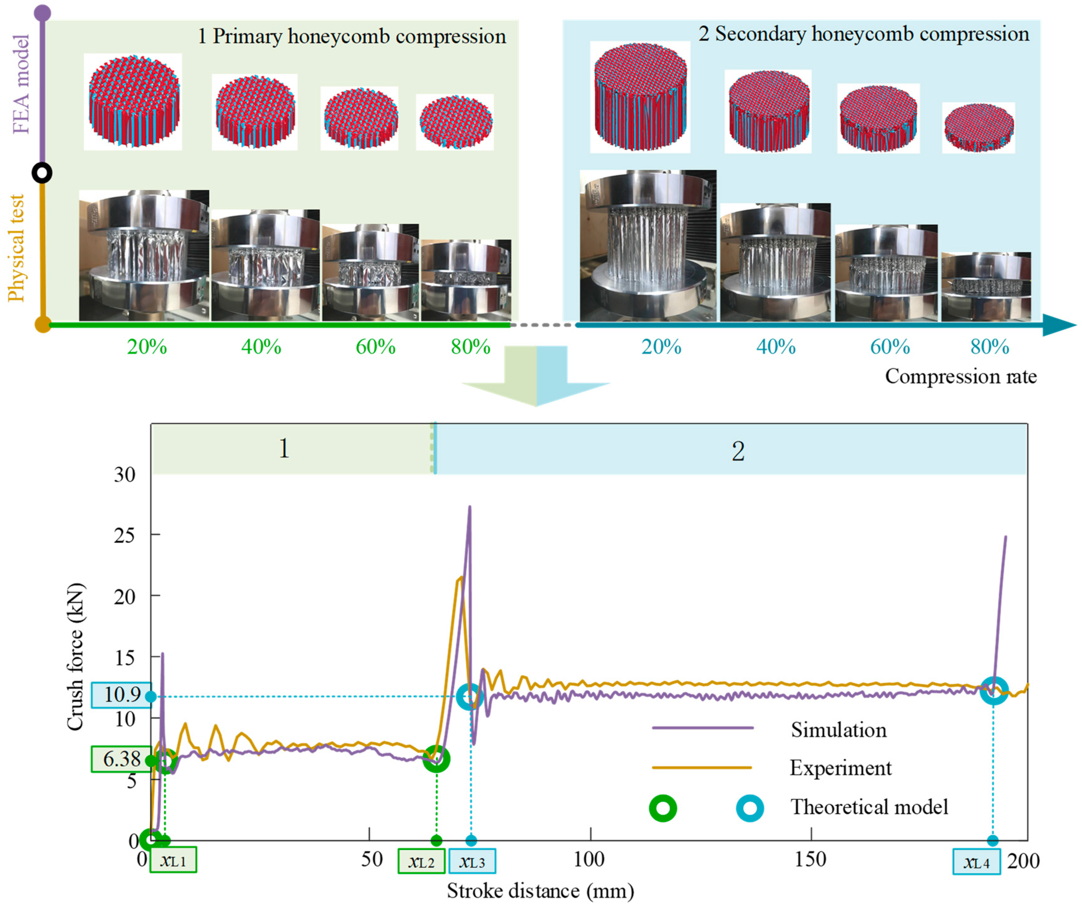
2.3. Theoretical Model of Multistage Aluminum Honeycomb

Aluminum honeycomb exhibits superior energy absorption capability while maintaining good surface flatness during the compression process. These characteristics help reduce the sudden deformation of the structure caused by the impact; thereby, aluminum honeycomb is conducive to improving the landing smoothness of the vehicle.
During the landing process of the vehicle, it is challenging to precisely control its attitude and velocity at touchdown. Therefore, to ensure a relatively smooth landing process, the landing gear is not only required to work efficiently under normal conditions, but also manage the extreme landing situation of single-leg touchdown. In this case, the buffering material within a single leg needs to possess the ability to absorb a significant portion of the vehicle’s impact energy. Hence, the two-stage aluminum honeycomb (the specific parameters are shown in Table 1) was employed in this experiment, and the theoretical energy absorption capacity of the primary aluminum honeycomb is sufficient for the general situation (vertical landing situation). Moreover, when the extreme situation occurs, both the primary and secondary aluminum honeycomb in a single leg will successively participate in energy absorption to ensure a smooth and stable landing for the vehicle.
As the two-stage aluminum honeycomb theoretical model shows in Figure 5, assuming that the stiffnesses of the elastic section and the plastic section of the primary and the secondary aluminum honeycomb are  k b 1 k b 2 k b 3 , and  k b 4 , respectively, and xL1, xL2, xL3, and xL4 represent the distance from the initial point of the multistage aluminum honeycomb, the force–displacement and energy–displacement relationships of the multistage aluminum honeycomb are as follows:
F b = { k b 1 x b 0 x b < x L 1 k b 1 x L 1 + k b 2 ( x b x L 1 ) x L 1 x b < x L 2 k b 1 x L 1 + k b 2 ( x L 2 x L 1 ) + k b 3 ( x b x L 2 ) x L 2 x b < x L 3 k b 1 x L 1 + k b 2 ( x L 2 x L 1 ) + k b 3 ( x L 3 x L 2 ) + k b 4 ( x b x L 3 ) x L 3 x b < x L 4
E b = { 1 2 k b 1 x b 2 0 x b < x L 1 E b 1 p + 1 2 k b 2 ( x b x L 1 ) 2 + k b 1 x L 1 ( x b x L 1 ) x L 1 x b < x L 2 E b 2 p + ( k b 2 ( x L 2 x L 1 ) + k b 1 x L 1 ) ( x b x L 2 ) + 1 2 k b 3 ( x b x L 2 ) 2 x L 2 x b < x L 3 E b 3 p + ( k b 2 ( x L 2 x L 1 ) + k b 1 x L 1 + k b 3 ( x L 3 x L 2 ) ) ( x b x L 2 ) + 1 2 k b 4 ( x b x L 3 ) 2 x L 3 x b < x L 4
Among the above equations,
E b 1 p = 1 2 k b 1 x L 1 2 ,
E b 2 p = 1 2 k b 1 x L 1 2 + 1 2 k b 2 ( x L 2 x L 1 ) 2 + k b 1 x L 1 ( x L 2 x L 1 ) ,
E b 3 p = 1 2 k b 1 x L 1 2 + 1 2 k b 2 ( x L 2 x L 1 ) 2 + k b 1 x L 1 ( x L 2 x L 1 ) + ( k b 2 ( x L 2 x L 1 ) + k b 1 x L 1 ) ( x L 3 x L 2 ) + 1 2 k b 3 ( x L 3 x L 2 ) 2
where the superscript p represents the impact energy stored in the previous stage by the aluminum honeycomb.
In the model simulation of the vertical landing process of the vehicle, set  k b 2 = 0 k b 4 = 0 , that is, assuming that the plastic section of the multistage aluminum honeycomb has ideal plastic behavior.

2.4. Coupling of the Multi-Impact and Buffering

In each state of the vehicle landing process, the primary impulse needs to be selected in the first place, followed by a network of relationships between the primary impulse and all kinds of secondary impulses. When only either the foot–ground impact or buffering behavior is activated (state S3 or state S4) in a state, the elastic impulse is preferred as the primary impulse; in this case, no coupling occurs between the buffering behavior and the foot–ground impact. However, the duration of this situation is relatively short.
In the state where both foot–ground impact and buffering are activated, as shown in Figure 6, the normal impulse of foot–ground impact  I z s  is prioritized as the primary impulse, while the buffering impulse  I b , auxiliary pillar impulse  I a , tangential impact impulse  I t , and normal damping impulse  I z d  act as secondary impulses.

3. Implementation and Results of Simulation and Experiment of the Vertical Landing Process of the Vehicle

3.1. Simulation of the Vertical Landing Process

During the experimental process, the friction at the joints and aluminum honeycomb sleeves of the landing gear, as well as the presence of installation clearances, can absorb part of the impact energy in the landing process, which will have an uncertain effect on the experimental data. Therefore, in the axial direction of the main pillar, a damping force  ( F b d = D b v b F b h )  was added to simulate this damping effect and friction loss. Additionally, the force–displacement characteristics of an aluminum honeycomb may also change under multiple impacts; however, in the simulation, it was assumed that the force–displacement relationship of the aluminum honeycomb under multiple impact remains the same as it was during the initial loading. The structure parameters of the vehicle used in the simulation of landing process are shown in Figure 7, and the simulation calculation process is shown in Figure 8.
The symbols, meanings, and values of parameters used in the simulation of vertical landing process of the vehicle are shown in Table 2.
By applying the proposed impact–buffering coupling model, the mass of the main body was set as 1120 kg, while the mass of foot was 1 kg, the vertical landing process of the vehicle was simulated, and the results are presented below. The normal and tangential velocity, as well as the transformation of the tangential motion pattern of the center of mass of the foot, are shown in Figure 9. From the figure, it can be observed that the vehicle makes initial contact with the ground at 0.2 s; the first impact between the vehicle and the ground occurs at this moment, until the vehicle leaves the ground around 0.38 s, signifying the end of the first impact. At 0.43 s, the vehicle experiences the second impact with the ground, which lasts until 0.53 s. Finally, at 0.54 s, the vehicle undergoes its third final touchdown. Subsequently, the vehicle’s landing process nonlinear system enters a damped periodic oscillation until it reaches a completely stable state.
It can be seen from Figure 9 that, during the first impact between the vehicle and the ground, the impact number between the foot and the ground is the largest; during this period, the velocity of foot decreases from the initial value of −2 m/s to −0.21 m/s. Additionally, there is a sudden change in the amplitude of the foot velocity at 0.28 s, which is attributed to the compression of the secondary aluminum honeycomb in the buffering device. The indicator factor in Figure 9b represents different tangential motion patterns, where a value of 1 indicates the impact point is slipping, 0 means that it sticks, and 0.5 means that the vehicle is not in contact with the ground. Based on the above, it can be observed from Figure 9c that during the first impact, the predominant pattern of tangential motion of the contact point remains stuck, with only two brief periods of slipping. In addition, the two periods of slipping are slightly different in behavior; they all happen in the later stage of the two aluminum honeycombs’ compressing process, but the second slipping is more continuous. The slipping of the impact point in the second impact is very brief and happens just before the vehicle leaves the ground; thereafter, the tangential motion pattern of the impact point always remains stuck.
From Figure 10a,b, in the first impact, a turning point caused by different stages of aluminum honeycombs during landing can be found. In Figure 10b, together with the detailed view, the inclination angle of the foot position decreases continuously from the first to the third impact, indicating that the first impact of the foot will create the deepest pit on the ground, and the depth and sliding distance will progressively decrease successively in the later impact.
Based on phase diagram Figure 11, it can be observed that in the early stage of the three collisions between the vehicle and the ground, the motion of the foot exhibits limited convergence behavior, and there may even be a slight tendency to deviate from the stable point in the medium stage. However, in the late stage of the impact, a significant improvement in convergence is observed.
As shown in Figure 12, the peak acceleration of the foot reaches 1489 m/s2 in the first impact and drops to 367 m/s2 and 256 m/s2 in the second and third impact, respectively. Furthermore, during the first and second impact, due to the temporary participation of the secondary aluminum honeycomb in the landing, the acceleration increases suddenly and then levels off.
From the buffering velocity diagram (Figure 13a), the maximum buffering velocity of the first, second, and third impact is 0.8 m/s, 0.09 m/s, and 0.05 m/s, respectively. In the early stage of the first impact, the buffering velocity increases sharply in the early stage, making the primary aluminum honeycomb enter the plastic section rapidly; as a result, the buffering velocity exhibits a smaller oscillation amplitude and a steep trend. Unlike the aforementioned stage of the impact, at the time when the primary aluminum honeycomb is completely compressed and the compression of the secondary aluminum honeycomb starts, the elastic section of the secondary aluminum honeycomb plays a major role, and the vast majority of the kinetic energy of the vehicle has been absorbed; thus, the buffer velocity will experience continual oscillation. From Figure 13b, the buffer stroke reaches 66.5 mm after the first impact, accounting for 97.8% of the total stroke (68 mm) of the landing, which shows that the aluminum honeycomb is capable of quickly absorbing the impact energy, while also confirming the high buffering performance of the multistage aluminum honeycomb.
In Figure 14, the velocity and position of the center of mass of the main body experience the largest reduction after the first impact, then gradually stabilize during the subsequent two collisions. Moreover, the position–velocity phase diagram (Figure 14c) indicates that the convergence amplitude is the largest during the first impact; after the small convergence process of two subsequent collisions, the vehicle system will reach a stable state after experiencing a damped periodic oscillation.
From Figure 15, it can be seen that during the first impact, the secondary aluminum honeycomb also contributes to the landing of the vehicle, indicating that the primary aluminum honeycomb has been fully compressed. In the second impact, the buffering force also hits the threshold of the secondary aluminum honeycomb, but quickly diminishes. Moreover, only the elastic sections of the first and second aluminum honeycomb are involved in the subsequent impact and system oscillation after the first impact.
Based on Figure 16a, it can be found that throughout the entire landing process of the vehicle, the overall energy variation in the system is consistent with the total dissipated energy, indicating that this model can ensure the conservation of energy and can track the changes in each kind of energy, as presented in Figure 16b–d, which further exhibits the effectiveness and accuracy of this model as well.

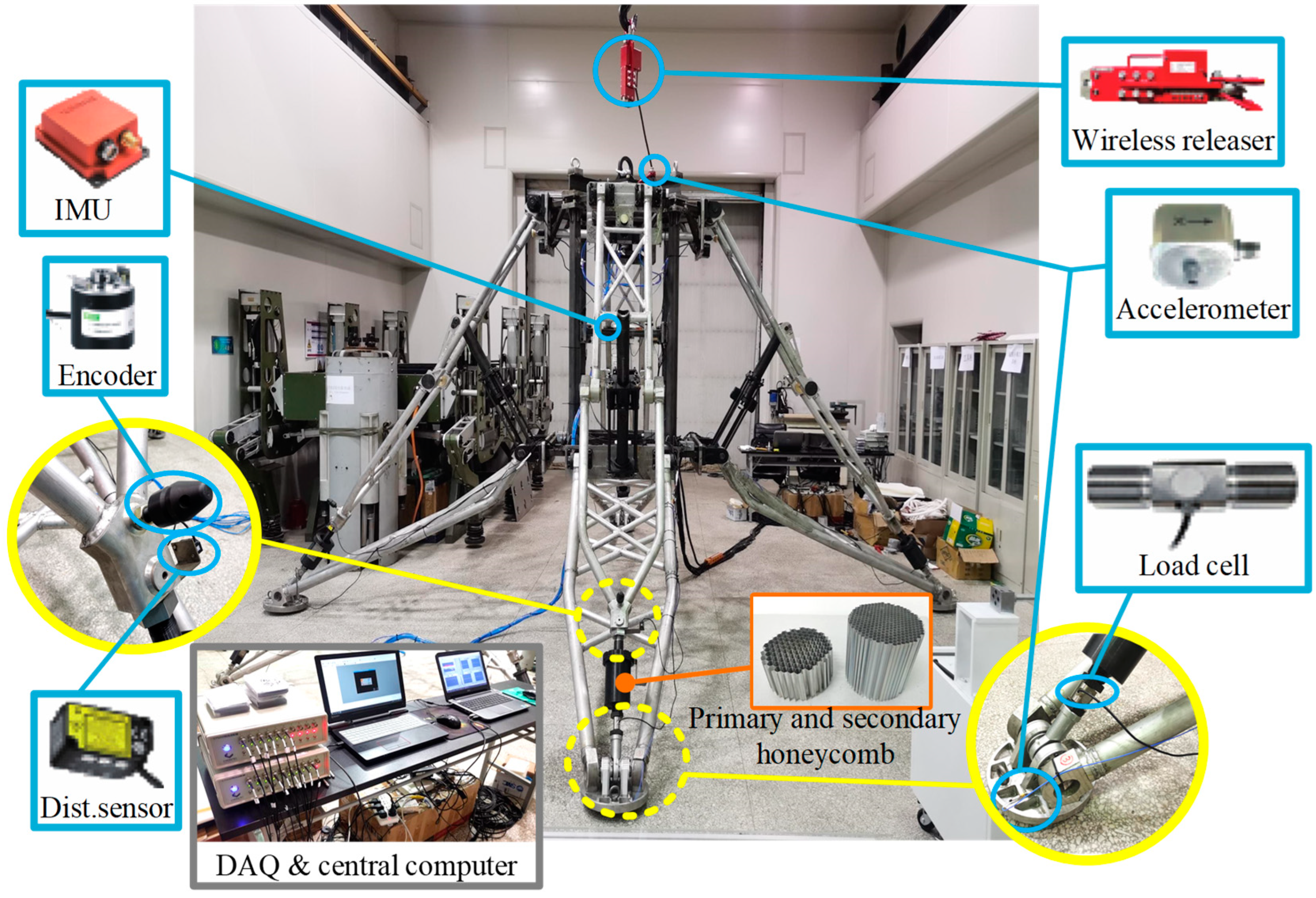
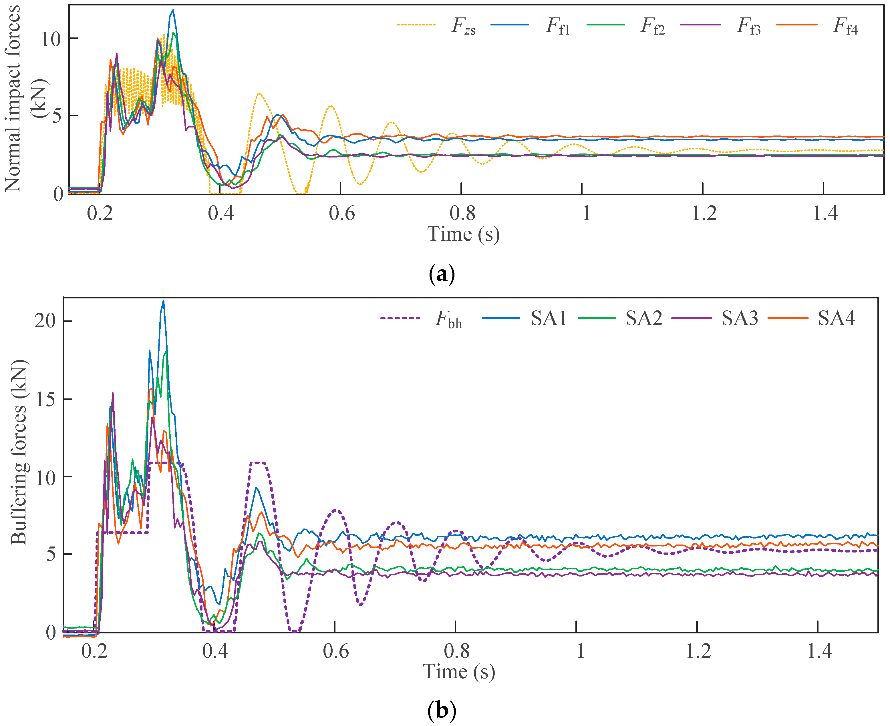
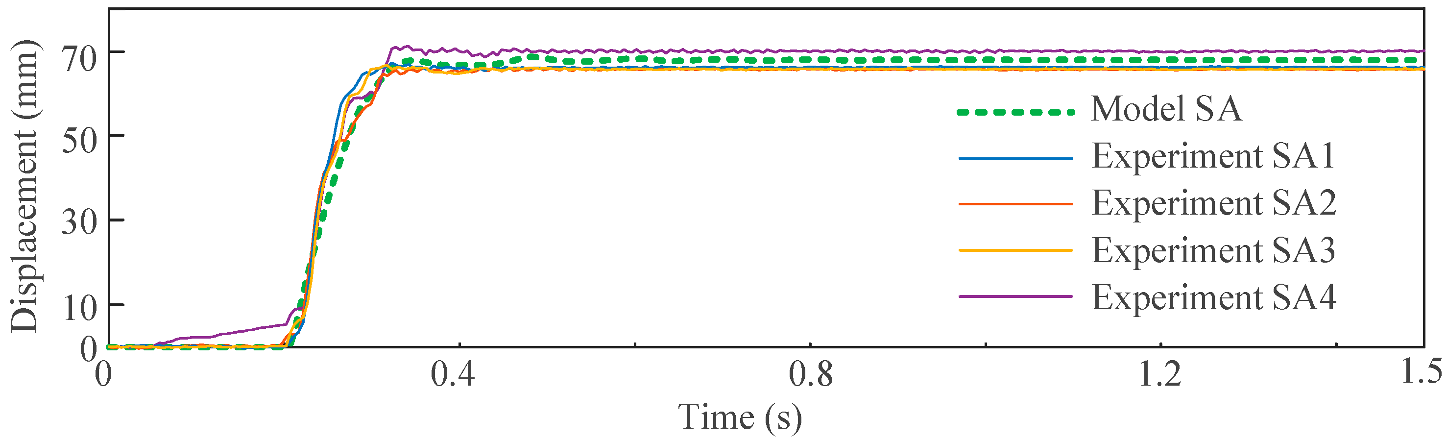
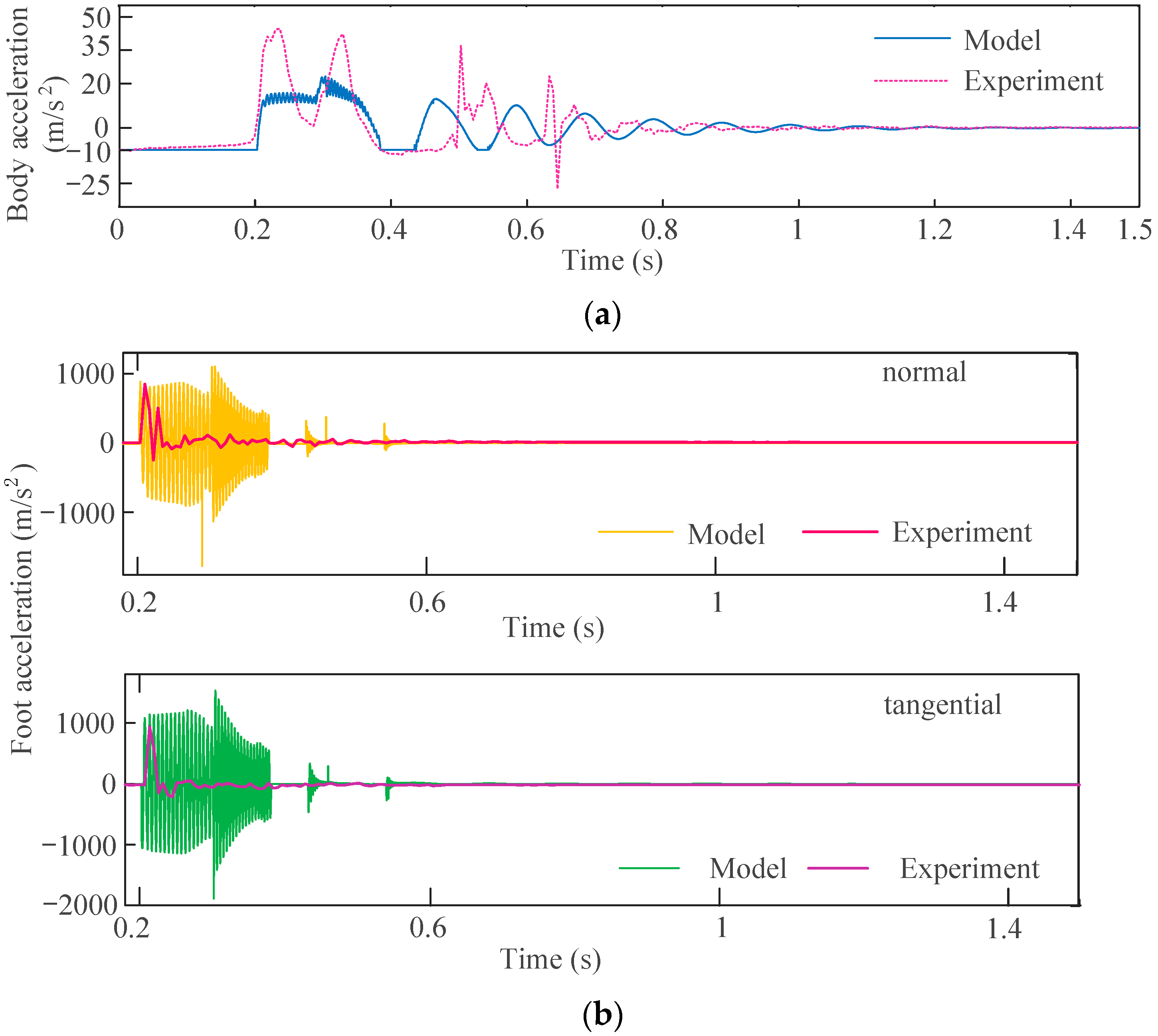
3.2. Implementation of the Vertical Landing Experiment of the Physical Vehicle

After successfully assembling the inverted-triangle landing gear, an experimental platform capable of conducting the vertical landing of the vehicle was built (as shown in Figure 17). Then, the experiments were carried out. The freefalling height of the landing gear was 0.2 m, equal as the simulation height (Hheight); the results are represented below.
By comparing the experimental results with the simulation results, it can be seen from Figure 18 that both the experimental and simulation landing processes of the vehicle experienced the situation of rebound; however, there existed differences between the theoretical model and the experimental setups as below. 1. During the first impact section, unlike the results of the experiment, the simulated force oscillated when the plastic sections of the multistage aluminum honeycomb started to contribute to the landing, as a result of the foot–ground impact. 2. The experimental force curve briefly exhibits a sharp peak before entering the plateau stage, the analytical model prediction percentage error of the impact force peak value is 9.9%, and this sharp peak difference is more obvious in the comparison of the buffering force between the experimental results and the simulation results; the percentage error was 19.72%, while the prediction percentage errors of the impact force and the buffering force in the steady values were 9.76% and 11.40%, respectively. The existence of the sharp peak was mainly because the precompression treatment of the multistage aluminum honeycomb used in the experiments could not completely eliminate the force peak before the plastic section, while in the simulation, the multistage aluminum honeycomb was assumed to be an ideal smooth transition elastic–plastic material. 3. From the data of the experiment, after the first impact, the vehicle will undergo another touchdown before entering the oscillation phase until stabilization. However, in the simulation, the vehicle rebounded twice. The one reason for this inconsistency is that the structural damping of the landing gear in the actual landing is unknown, while the structural damping imposed in the simulation is typical  ( F b d = D b v b F b h ) . Moreover, due to the incomplete rigid connection between the aluminum honeycomb and the sleeve, the rod and the foot may slip down to remain in contact with the ground when the vehicle rebounds; these all lead to differences in energy dissipation between the experimental process and the simulation.
From Figure 19, the stroke variation history of the buffer in the experiments aligns well with the simulation; the model prediction percentage error of the stroke displacements in the steady state is 0.28%. After the first impact, both the experimental and simulated buffer undergo a certain retraction; this can be attributed to the release of elastic energy absorbed by the elastic section of the multistage aluminum honeycomb as the impact approaches its end.
According to Figure 20a, the trends in the results of the experiment and simulation during the first impact matched with each other well, except for the small-scale oscillation in the simulation process. However, the peak of the acceleration measured in the experiment (43.5 m/s2) was higher than the simulated peak acceleration (23.8 m/s2), which may be a result of the incomplete removal of force peaks of the aluminum honeycomb used in the experiment. In addition, the timelines of the subsequent impact of the experiment and simulation were slightly misaligned due to unknown structural damping, but the trend was consistent, except for the peaks. From Figure 20b, it can be found that the oscillation phase of the acceleration of the experiment during the first impact was shorter and the frequency was lower compared to the simulation; moreover, there was no significant fluctuation in the subsequent impact. Apart from the sampling error of the equipment used in the experiment, these differences can be attributed to the simplification of the theoretical model, which can be elaborated as follows. Compared with the perfect elasticity in the bi-stiffness spring model and aluminum honeycomb model of the simulation, the elastic characteristics of the foot–ground impact during the landing process will be weakened by the friction of the mechanical structure as well as the damping between the foot and the ground during the experiment, leading to a significant reduction in oscillation upon (during) the impact between the foot and the ground in the experiments. The vertical landing vehicle with the inverted-triangle landing gear was translated into a rigid–flexible coupling multibody system, and we regarded the vertical landing process of the vehicle as a dynamics convergence problem of a complex nonlinear dissipative system. We broke it down into four subsystems—four states—correspondingly, and based on the above, we studied the problem using the state transition method.

4. Conclusions

This paper presents the explicit modeling of a reusable vehicle at the vertical landing stage wherein the discrete-impulse-based state transition approach is employed to characterize the intrinsic nonlinear coupling effect between the landing impact and the crushing-type buffering. In particular, a 3D multi-impact model is constructed to feature the stick and slip stages of the foot–ground collision. An experiment-guided buffering model is established to depict the crushing behaviors of the multistage aluminum honeycomb element mounted in the landing gear. The evolution of the reusable vehicle’s crucial states including the trajectory of the CoM, body attitude, as well as internal forces can be predicted by using derived explicit models in contact-rich scenarios. Analytical models with an elaborately designed state transition regime are verified via both simulation and experiments involving the 20 cm freefalling of a scaled reusable vehicle prototype. Specifically, in the foot–ground impact section, the prediction percentage errors of the impact force and the buffering force in the steady values are 9.76% and 11.40%, respectively. When it comes to the peak values, these percentage errors are 9.9% and 19.72%, respectively. In the buffering section, the prediction percentage error of the stroke displacements in the steady state is 0.28%. Eventually, the presented theoretical work provides a potential analytical tool not only to shed light on the dynamical behavior of reusable vehicles with legged landing gear in complex environments, but also guide the design and optimization of the landing gear mechanism.

Author Contributions

Conceptualization, H.Y. and H.G.; methodology, H.Y. and Y.W.; software, Y.W.; validation, Z.Y., B.T. and J.X.; formal analysis, Y.W.; investigation, Y.W. and J.X.; resources, H.Y. and H.G.; data curation, Y.W., Z.Y. and B.T.; writing—original draft preparation, Y.W.; writing—review and editing, H.Y.; visualization, H.Y.; supervision, H.Y. and H.G.; project administration, H.Y. and H.G.; funding acquisition, H.Y. and H.G. All authors have read and agreed to the published version of the manuscript.

Funding

This research received no external funding.

Data Availability Statement

Not applicable.

Conflicts of Interest

The authors declare no conflict of interest.

Nomenclature

Z, Y, XThe geodetic coordinate system
z0, y0, x0The main body’s initial companion coordinate system
z1, y1, x1The main body’s companion coordinate system
zj, yj, xjThe coordinate system of the impact between the foot i and the ground
z, y, xThe displacement of the z, y, x visual spring of the foot–ground impact or the coordinate of the foot–ground impact (mm)
n, w, uThe coordinate of the main pillar
θkk ∈ [1, 3], respectively, represents the rotation angle of each coordinate axis (°)
m1The mass of the main body (kg)
m2iThe mass of the foot i (kg)
qiThe impact point between the foot i and the ground
piThe origin of the coordinate of the main pillar i
Ebi, Fbi, IbiThe buffer energy, force, and impulse of leg i, respectively (J, N, N·s)
Ezsi, Fzsi, IzsiThe energy, force, and impulse of the normal spring of the foot–ground impact (J, N, N·s)
EtanThe elastic energy of the tangential springs (J)
vziThe normal velocity of the foot i (m/s)
vbiThe buffering velocity of leg i (m/s)
VtanThe tangential velocity of the touchdown foot (m/s)
VsThe slipping velocity of the touchdown foot (m/s)
ZfiThe normal displacement of the foot i (m)
FliThe transverse force exerted on the main body by the touchdown foot i (N)
α β Indicator of the x and y virtual spring states; 1 means the spring is compressed. Otherwise, it will be set as −1
IzdThe normal damping impulse of the foot–ground impact (N·s)
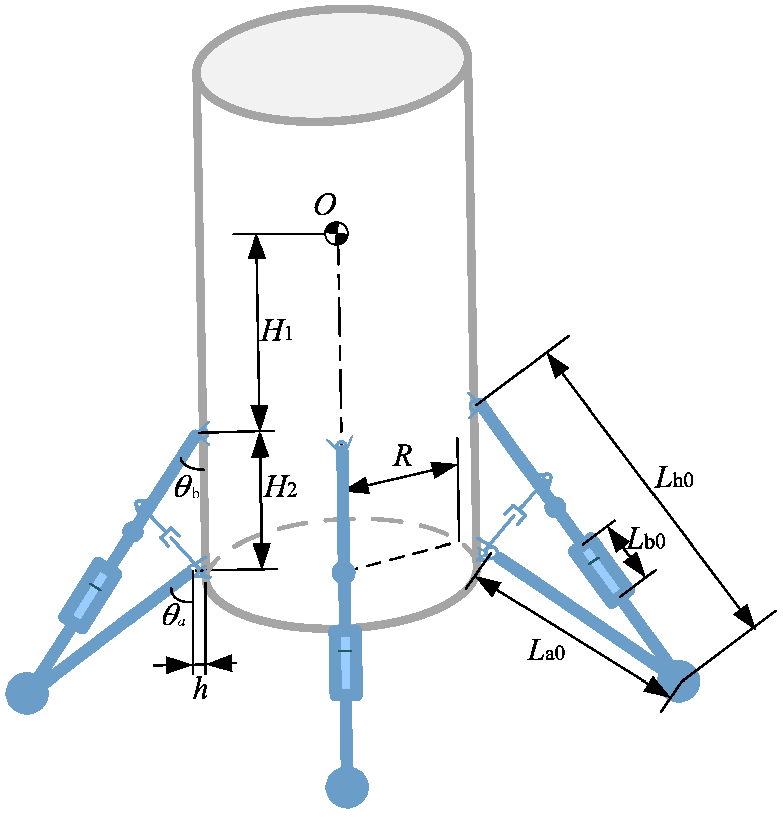
θbiThe angle between main pillar i axis and main body axis (°)
θaiThe angle between auxiliary pillar i axis and main body axis (°)
hThe relative lateral distance of the auxiliary strut (m)
H1The longitudinal distance from the center of mass of the main body to the main pillar (m)
H2The longitudinal distance from main strut to auxiliary pillar (m)
RThe radius of the body (m)
xbThe stroke of the buffer
kb1, kb2, kb3, kb4The stiffness coefficients of elastic and plastic section of the two-stage aluminum honeycomb
Lh0The initial length of the main pillar (m)
Lb0The maximum stroke of the buffer device (m)
La0The initial length of the auxiliary pillar (m)
xL1The elastic section length of the primary aluminum honeycomb (mm)
xL2The length of primary aluminum honeycomb (mm)
xL3The length from the initial buffer point to the elastic section of the secondary aluminum honeycomb (mm)
xL4The length of two stages of aluminum honeycomb (mm)
kThe coefficient of stiffness of the normal spring
ktanThe coefficient of stiffness of the tangential spring
μThe coefficient of friction
γ1 minus the coefficient of restitution
χThe coefficient of damping of foot–ground impact
DbThe coefficient of damping of structure of the landing gear
HheightFree-falling height (m)

References

  1. Zhou, H.; Wang, X.; Wang, Y.; Zhan, J.; Zhang, J. Research on a coupler with arc surface contact and its effect on a train collision. J. Rail Rapid Transit 2023, 237, 479–489. [Google Scholar] [CrossRef]
  2. Zhou, H.; Wang, Y.; Wang, X.; Zhan, J.; Zhang, J. Influence of the coupler and buffer device on the train collision safety. J. Rail Rapid Transit 2023, 237, 385–393. [Google Scholar]
  3. Su, Y.; Hou, X.; Li, L.; Cao, G.; Chen, X.; Jin, T.; Jiang, S.; Li, M. Study on impact energy absorption and adhesion of biomimetic buffer system for space robots. Adv. Space Res. 2020, 65, 1353–1366. [Google Scholar] [CrossRef]
  4. Yin, K.; Sun, Q.; Gao, F.; Zhou, F. Lunar surface soft-landing analysis of a novel six-legged mobile lander with repetitive landing capacity. J. Mech. Eng. Sci. 2022, 236, 1214–1233. [Google Scholar]
  5. Hou, W.; Hao, Y.; Wang, C.; Chen, L.; Li, G.; Zhao, B.; Wang, H.; Wei, Q.; Xu, S.; Feng, K.; et al. Theoretical and experimental investigations on high-precision micro-low gravity simulation technology for lunar mobile vehicle. Sensors 2023, 23, 3458. [Google Scholar]
  6. Lin, Q.; Ren, J. Investigation on the horizontal landing velocity and pitch angle impact on the soft-landing dynamic characteristics. Int. J. Aerosp. Eng. 2022, 16, 3277581. [Google Scholar] [CrossRef]
  7. Yin, K.; Qi, C.; Gao, Y.; Sun, Q.; Gao, F. Landing control method of a lightweight four-legged landing and walking robot. Front. Mech. Eng. 2022, 17, 51. [Google Scholar]
  8. Zhang, Z.Q.; Chen, D.S.; Chen, K.W. Analysis and comparison of three leg models for bionic locust Robot based on landing buffering performance. Technol. Sci. 2016, 59, 1413–1427. [Google Scholar]
  9. Chen, D.S.; Zhang, Z.Q.; Chen, K.W. Dynamic model and performance analysis of landing buffer for bionic locust mechanism. Acta Mech Sin. 2016, 32, 551–565. [Google Scholar]
  10. Ji, S.; Liang, S. DEM-FEM-MBD coupling analysis of landing process of lunar lander considering landing mode and buffering mechanism. Adv. Space Res. 2021, 68, 1627–1643. [Google Scholar]
  11. Ding, J.; Liu, X.; Dong, Y.; Wang, C. Stability analysis of mars soft landing under uncertain landing conditions and two landing strategies. Aircr. Eng. Aerosp. Technol. 2022, 94, 1883–1891. [Google Scholar]
  12. Yu, H.; Tian, B.; Yan, Z.; Gao, H.; Zhang, H.; Wu, H.; Wang, Y.; Shi, Y.; Deng, Z. Watt linkage-based legged deployable landing mechanism for reusable launch vehicle: Principle, prototype design, and experimental validation. Engineering 2023, 20, 120–133. [Google Scholar] [CrossRef]
  13. Aghili, F. Modeling and analysis of multiple impacts in multibody systems under unilateral and bilateral constrains based on linear projection operators. Multibody Syst. Dyn. 2019, 46, 41–62. [Google Scholar]
  14. Natsiavas, S.; Passas, P.; Paraskevopoulos, E. A time-stepping method for multibody system with frictional impacts based on a return map and boundary layer theory. Int. J. Non Linear Mech. 2021, 131, 103683. [Google Scholar] [CrossRef]
  15. Lei, B.; Zhang, M.; Lin, H.; Nie, H. Optimization design containing dimension and buffer parameters of landing legs for reusable landing vehicle. Chin. J. Aeronaut. 2022, 35, 234–249. [Google Scholar]
  16. Dong, Y.; Ding, J.; Wang, C.; Wang, H.; Liu, X. Soft landing stability analysis of a Mars Lander under uncertain terrain. Chin. J. Aeronaut. 2022, 35, 377–388. [Google Scholar] [CrossRef]
  17. Arailopoulos, A.; Giagopoulos, D. Nonlinear constitutive force model selection, update and uncertainty quantification for periodically sequential impact applications. Nonlinear Dyn. 2020, 99, 2623–2646. [Google Scholar]
  18. Poursina, A.-M.; Nikravesh, P.-E. Optimal damping coefficient for a class of continuous contact models. Multibody Syst. Dyn. 2020, 50, 169–188. [Google Scholar]
  19. Shen, Y.; Kuang, Y.; Wang, W.; Zhao, Y.; Yang, J.; Tian, A. Frictional impact analysis of an elastoplastic multi-link robotic system using a multi-timescale modelling approach. Nonlinear Dyn. 2019, 98, 1999–2018. [Google Scholar]
  20. Wang, H.; He, T.; Wang, C. A comprehensive performance optimization method for the honeycomb buffer of a legged-type lander. Aircr. Eng. Aerosp. Technol. 2021, 93, 821–831. [Google Scholar]
  21. Xie, S.; Du, X.; Zhou, H.; Wang, J.; Chen, P. Crashworthiness of Nomex honeycomb-filled anti-climbing energy absorbing devices. Int. J. Crashworthiness 2021, 26, 121–132. [Google Scholar] [CrossRef]
  22. Zhou, D.; Wang, X.; Zheng, Q.; Fu, T.; Wu, M.; Sun, X. A nonlinear occupant-restraint system model for human injuries caused by vertical impact. Nonlinear Dyn. 2021, 105, 3093–3115. [Google Scholar] [CrossRef]
  23. Yuan, Q.; Chen, H.; Nie, H.; Zheng, G.; Wang, C.; Hao, L. Soft-landing dynamic analysis of a manned lunar lander em-ploying energy absorption materials of carbon nanotube buckypaper. Materials 2021, 14, 6202. [Google Scholar] [CrossRef]
  24. Zhou, J.; Jia, S.; Qian, J.; Chen, M.; Chen, J. Improving the buffer energy absorption characteristics of movable lander-numerical and experimental studies. Materials 2020, 13, 3340. [Google Scholar] [CrossRef] [PubMed]
  25. Zhou, J.; Ma, H.; Jia, S.; Tian, S. Mechanical properties of multilayer combined gradient cellular structure and its application in the WLL. Heliyon 2023, 9, e14825. [Google Scholar] [CrossRef] [PubMed]
  26. Jia, Y.B. Three-dimensional impact: Energy-based modeling of tangential compliance. Int. J. Robot. Res. 2013, 32, 56–83. [Google Scholar] [CrossRef]
  27. Jia, Y.B.; Mason, M.-T.; Erdmann, M.-A. Multiple impacts: A state transition diagram approach. Int. J. Robot. Res. 2013, 32, 84–114. [Google Scholar] [CrossRef] [Green Version]
Figure 1. Schematic diagram of the theoretical model of the vehicle with inverted-triangle landing gear.
Actuators 12 00307 g001
Figure 2. State machine of the vertical landing process of the vehicle.
Actuators 12 00307 g002
Figure 3. The coordinate of the impact point and the center of mass (CoM) of the foot.
Actuators 12 00307 g003
Figure 4. The tangential velocity.
Actuators 12 00307 g004
Figure 5. Experimental and finite element analysis (FEA) simulation results of the multistage aluminum honeycomb and theoretical model of mechanical properties of the multistage aluminum honeycomb.
Actuators 12 00307 g005
Figure 6. The coupling of the foot–ground impact and aluminum honeycomb buffering of the inverted-triangle landing leg.
Actuators 12 00307 g006
Figure 7. Theoretical model of the vertical landing vehicle.
Actuators 12 00307 g007
Figure 8. Calculation flow of vertical landing process.
Actuators 12 00307 g008
Figure 9. Velocity of foot and tangential motion patterns in the first impact: (a) normal velocity, (b) tangential velocity, and (c) tangential spring velocity and centroid velocity of foot.
Actuators 12 00307 g009
Figure 10. Foot position: (a) normal and tangential position of the touch-down foot; (b) history of position of the center of mass (CoM) of the foot.
Actuators 12 00307 g010
Figure 11. Velocity–position phase diagram of the foot: (a) normal; (b) tangential.
Actuators 12 00307 g011
Figure 12. Acceleration of foot: (a) normal; (b) tangential.
Actuators 12 00307 g012
Figure 13. Results of the buffer: (a) velocity; (b) buffer displacement.
Actuators 12 00307 g013
Figure 14. Results of main body of the vehicle: (a) velocity; (b) position of the centroid; (c) position–velocity phase diagram; (d) acceleration.
Actuators 12 00307 g014
Figure 15. History of buffering force, structural damping force, foot normal force, foot tangential force, and auxiliary pillar force.
Actuators 12 00307 g015
Figure 16. All kinds of energy of the system. (a) Total energy and total dissipated energy; (b) kinetic energy of the main body and foot; (c) elastic energy; (d) potential energy of the body and foot; (e) dissipated energy in the system.
Actuators 12 00307 g016
Figure 17. Measurement units.
Actuators 12 00307 g017
Figure 18. Force results of experiment and simulation: (a) the normal impact force and (b) the buffering force.
Actuators 12 00307 g018
Figure 19. Stroke results of experiment and simulation.
Actuators 12 00307 g019
Figure 20. Acceleration results of experiment and simulation: (a) the main body and (b) the foot.
Actuators 12 00307 g020
Table 1. Specifications of the multistage aluminum honeycomb cores.
Stage CategoryLength (mm)Diameter of
Section (mm)
Cell Size (mm)Sheet Thickness (mm)
Primary honeycomb72988.660.07
Secondary honeycomb125985.200.06
Table 2. The parameters used in the simulation.
SymbolValueSymbolValue
  θ b i 58.70   x L 2 57.60
  θ a i 35.11   x L 3 58.23
  h 0.092   x L 4 183.23
  H 1 0.25k2 × 106
  H 2 1.55   k t a n 7 × 10⁴
  R 0.60   μ 0.50
  L h 0 3.19   γ 0.50
  L b 0 0.18   χ 2 × 10⁻⁴
  L a 0 2.04   D b 1.50
  x L 1 0.47Hheight0.2
Disclaimer/Publisher’s Note: The statements, opinions and data contained in all publications are solely those of the individual author(s) and contributor(s) and not of MDPI and/or the editor(s). MDPI and/or the editor(s) disclaim responsibility for any injury to people or property resulting from any ideas, methods, instructions or products referred to in the content.

