1. Introduction
As industrialization accelerates, nations’ demand for oil and gas resources continues to grow [
1]. In this context, oil and gas pipelines, serving as essential means of energy transportation, hold a pivotal strategic position and economic value in national industrial development [
2]. However, over time, various defects may gradually emerge inside these pipelines, such as leakage points, pits, and corrosion [
3].
Oil and gas pipeline inspections currently rely heavily on manual methods, which have limitations and are inefficient in promptly detecting pipeline leaks [
4]. In recent years, pipeline robots have emerged as effective tools to improve the accuracy and efficiency of inspections and prevent pipeline leakage accidents. These specialized devices are designed for narrow spaces and offer strong adaptability and reliability [
5,
6]. They can be equipped with various sensors, such as ultrasonic, infrared, and magnetic flux leakage sensors, to detect defects such as leakage points, corrosion, and pits in pipelines [
7]. Additionally, pipeline robots possess data analysis and storage capabilities, allowing them to process and analyze collected information in real time and provide accurate and reliable results to maintenance personnel [
8].
Researchers including Shao et al. have categorized pipeline robots into three structural types: wheeled, tracked, and non-wheeled [
9]. Wheeled robots refer to robots that have drive wheels installed on their main body, creating a sealed contact with the inner wall of the pipeline, allowing the robot to move within the pipeline [
10,
11]. Miao et al. developed a wheeled pipeline isolation and plugging robot and investigated its dynamic characteristics during the traversal of weld seams [
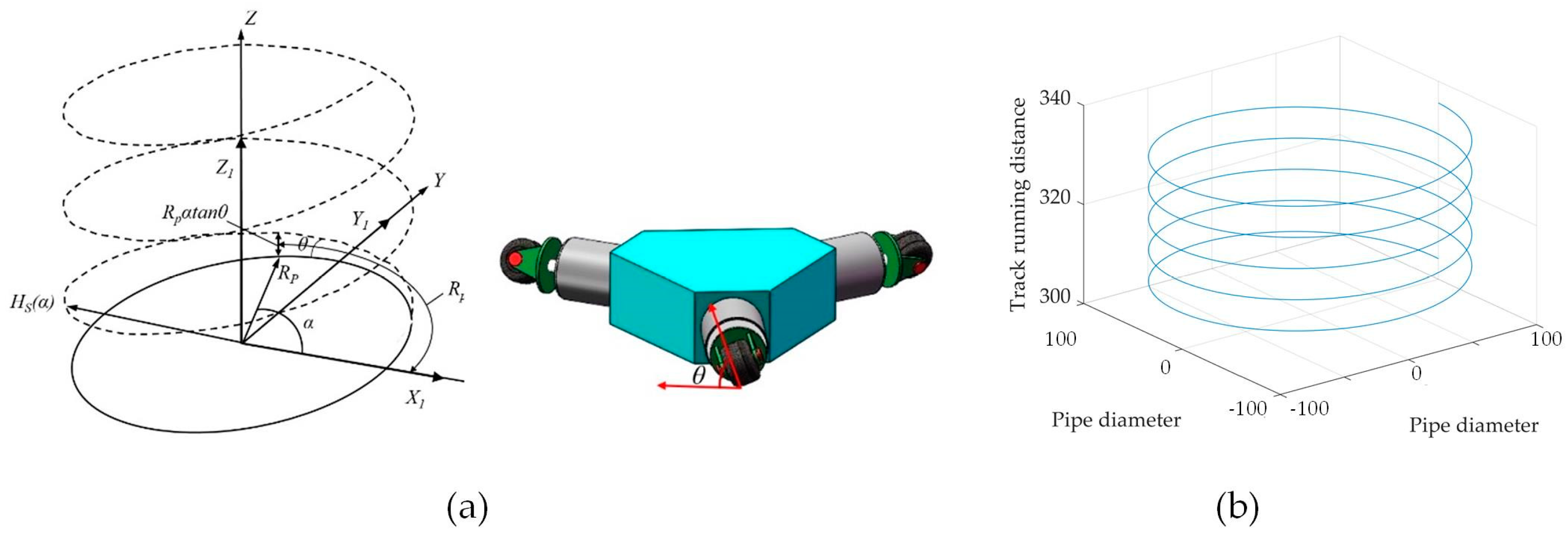
12]. Wheeled robots can be further classified based on their mode of motion, namely direct-wheel drive and spiral drive. Spiral drive robots are characterized as having the axis of their drive wheels at a certain angle with respect to the central axis of the pipeline, resulting in a spiral trajectory along the inner wall. A spiral pipeline robot was designed by Yonsei University in South Korea, capable of operating within branch pipelines with zero curvature radius and varying diameters [
13].
Tracked pipeline robots, unlike wheeled robots, feature tracks that provide a larger contact area with the pipeline. This design offers increased friction and superior traction, resulting in more reliable operation compared to wheeled robots. Zhang et al. developed a tracked pipeline inspection robot that allows for the individual speed adjustment of each track. This enables the robot to achieve posture adjustments within the pipeline and adapt to geometric constraints present in the pipeline environment [
14].
Non-wheeled pipeline robots, such as snake-like robots, utilize complex motion control algorithms to navigate and operate within pipelines [
15]. Gao and other researchers proposed a multi-link magnetic wheel pipeline robot that demonstrates good control performance in linear movement, turning, wall climbing, and obstacle crossing, among other aspects. This robot can adapt to various terrains effectively [
16].
In certain scenarios, robots employ tethered cable connections for their operations. In other operational environments, robots utilize wireless communication methods [
17]. However, wireless communication and positioning between robots and ground base stations face technical challenges in the context of buried oil and gas pipelines. The underground environment, consisting of soil, rock, concrete, and other materials, significantly weakens communication signals, reducing their transmission distance. Moreover, communication signals in underground environments may encounter reflection, refraction, and scattering within pipelines, resulting in delays, distortions, and interference. The complexity of the pipeline environment further hinders accurate signal localization [
18]. To address these challenges, researchers have proposed several solutions, such as the Kalman filter, an efficient linear optimal estimation algorithm that predicts system states based on incomplete and noisy measurement data [
19,
20,
21]. By integrating data from various sensors such as inertial measurement units (IMU), odometers, magnetometers, and optical sensors, the Kalman filter eliminates noise and provides accurate position and attitude estimation for robots within the pipeline [
22,
23]. Another solution is simultaneous localization and mapping (SLAM), a technology that enables robots to estimate their location within an unknown environment while constructing a map of that environment. SLAM assists pipeline robots in creating a map that contains pipeline geometry, running trajectories, and other relevant information. The SLAM algorithm continuously updates the robot’s position within the map [
24,
25,
26]. Wireless communication is also essential, and it is facilitated through radio frequency (RF) signals between robots and ground workstations. Common approaches include outdoor positioning based on relay nodes placed along a straight path [
27] and utilizing the radio frequency signal of the robot within a metal pipe, eliminating the need for ground operators to possess knowledge of the pipeline map. In the latter case, a radio frequency signal transmitter and receiver capture periodic received signal fading, which is then used to establish the robot’s positioning system based on the periodic signal fading [
28,
29].
Spiral pipeline robots have been widely utilized in specialized operations due to their simple structure and excellent performance in bending pipelines. However, these robots still face challenges related to insufficient traction and limited load capacity. To address these issues, this study presents a spiral pipeline robot designed with environmental detection and motion control capabilities. By examining multiple factors that affect the robot’s traction performance, this research aims to enhance the work efficiency and safety of the spiral pipeline robot.
2. Pipeline Inspection Robot System Design
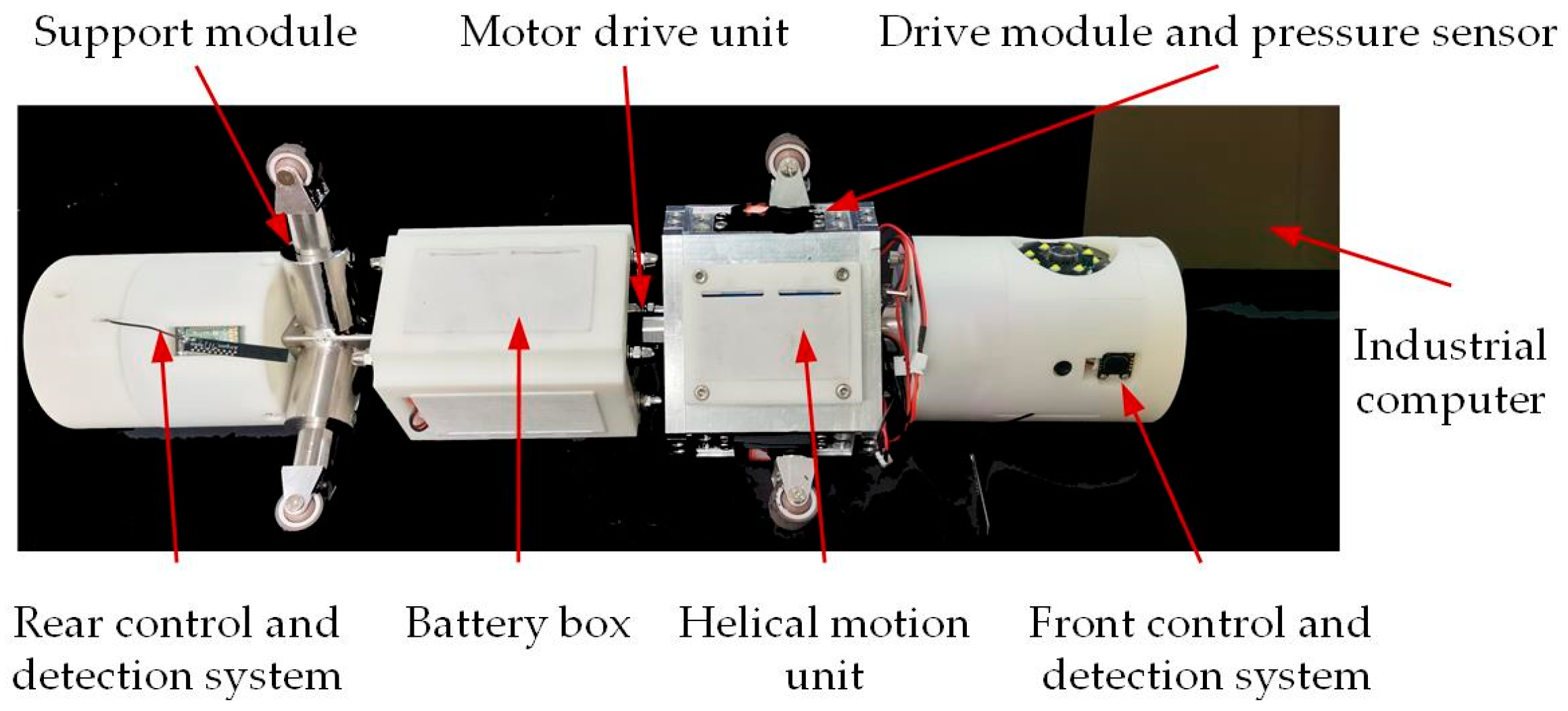
Figure 1 shows the main unit of the pipeline inspection robot. The external structure of the robot is composed of the robot spiral motion unit, the motor drive unit, the support unit, the battery box, the front detection and control unit, the rear detection and control unit and the upper unit. The robot specifications are shown in
Table 1.
2.1. Structure Design of Pipeline Robot
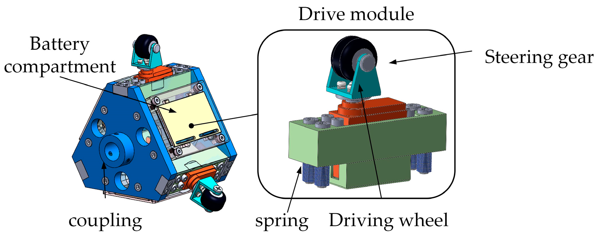
Figure 2 describes the structure of a spiral motion unit, which is an engineering component designed to operate in a pipe or similar cylindrical environment. The unit consists of three drive modules that are equidistantly positioned at 120° intervals around the circumference. Each module has a built-in spring and steering gear that both connect to a wheel frame. A driving wheel is attached to this frame using specialized bolts. The steering gear is fastened to a mounting frame with bolts, and four springs are evenly placed at the base of this frame, allowing the drive module to adapt to varying pipe diameters. The spiral motion unit has three battery compartments arranged circumferentially, and the module can be connected to a drive motor module through a coupling. The spiral motion unit features driving wheels on each module that are positioned at a specific angle, known as the spiral angle, with respect to the axis of the pipeline. This orientation enables the generation of a driving force along the pipeline through a mechanism.
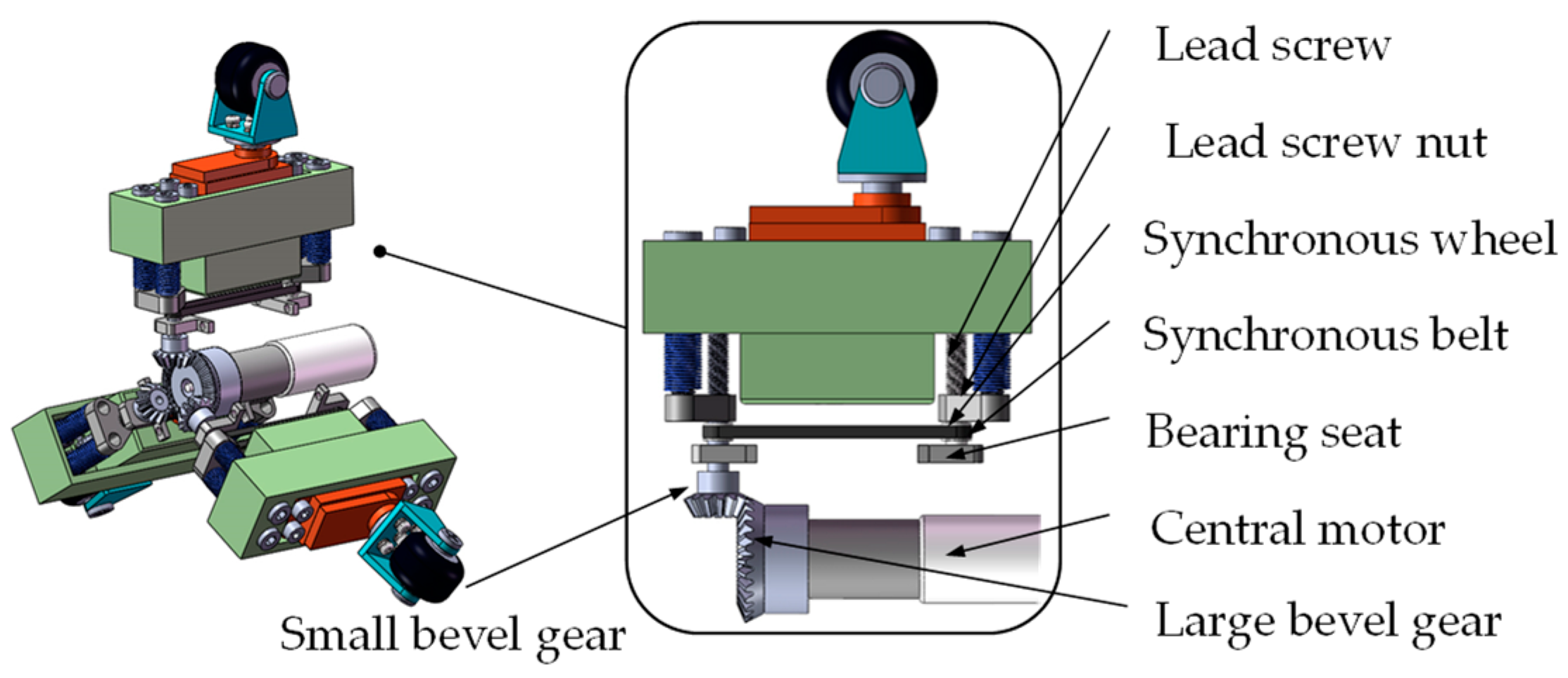
Figure 3 illustrates the central motor module positioned at the center of the robot. The central motor is connected to the large bevel gears via the output end, while the three small bevel gears are evenly distributed circumferentially, with a separation of 120 degrees between each gear. The small bevel gears are securely affixed to the lead screw, and upon driving the large bevel gears, the three small bevel gears commence rotation. This rotational motion is transmitted to the synchronous belt and the lead screw, thereby inducing movement of the lead screw nut. By compressing the spring around the smooth rod, the screw nut propels the entire drive module along the pipe’s diameter. Consequently, this motion instigates a variation in the positive pressure between the driving wheel and the inner wall of the pipe. To monitor the contact pressure between the driving wheels and the inner wall of the pipeline, pressure sensors are strategically placed between each driving module and its corresponding spring. By adjusting the spring compression of the central motor, it is possible to control the positive pressure exerted by the driving wheel, ensuring optimal performance and adaptability to various pipeline conditions.
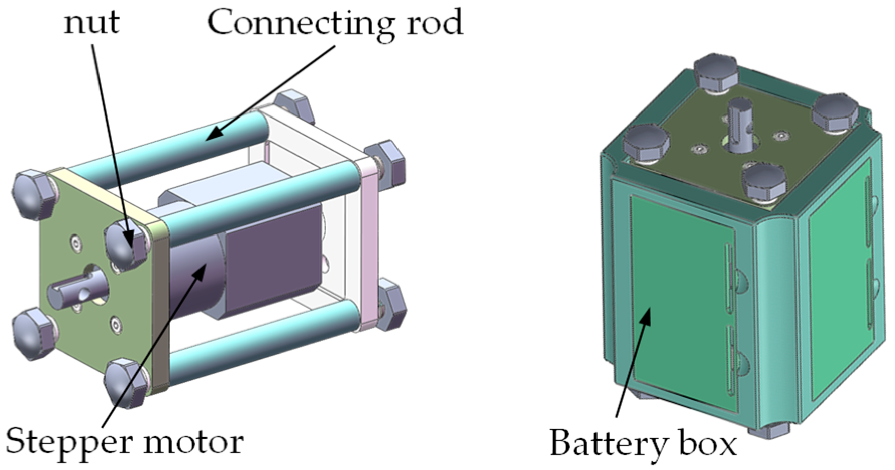
The motor driving unit is a crucial component of the system and primarily consists of a stepper motor, connecting rod, round nut, and battery box. As illustrated in
Figure 4, the battery housing serves as the primary support for the motor drive unit, with front and rear baffles connected by connecting rods. These rods are secured with four nuts on each side. The stepper motor is attached to one side baffle, and it powers the front and side spiral motion units to move circularly around the pipeline axis, enabling the robot to travel in a helical pattern within the pipeline. To supply the necessary power, the battery box is designed with four compartments to accommodate four lithium batteries.
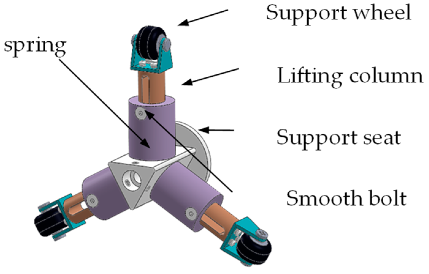
The support module, an essential component of the system, is composed of a support wheel, lifting column, support seat, spring, and smooth bolt.
Figure 5 illustrates the structure of the support module. The support seat serves as the main structural support, with three supporting units connected to the support frame by welding at 120° intervals around the circumference. The support module is designed to adapt to varying pipe diameters, ensuring that the support wheel maintains vertical contact with the inner wall of the pipe, providing effective support. Connected to the drive motor module through the rear support body, the support module can balance reverse torque generated during rotation. The support wheel is mounted on the wheel frame using child and mother bolts. The lifting column, equipped with a built-in spring, can move up and down to enable the support module to adapt to changes in pipe diameter, ensuring its effectiveness in providing the necessary support under different pipeline conditions.
2.2. Control System Design
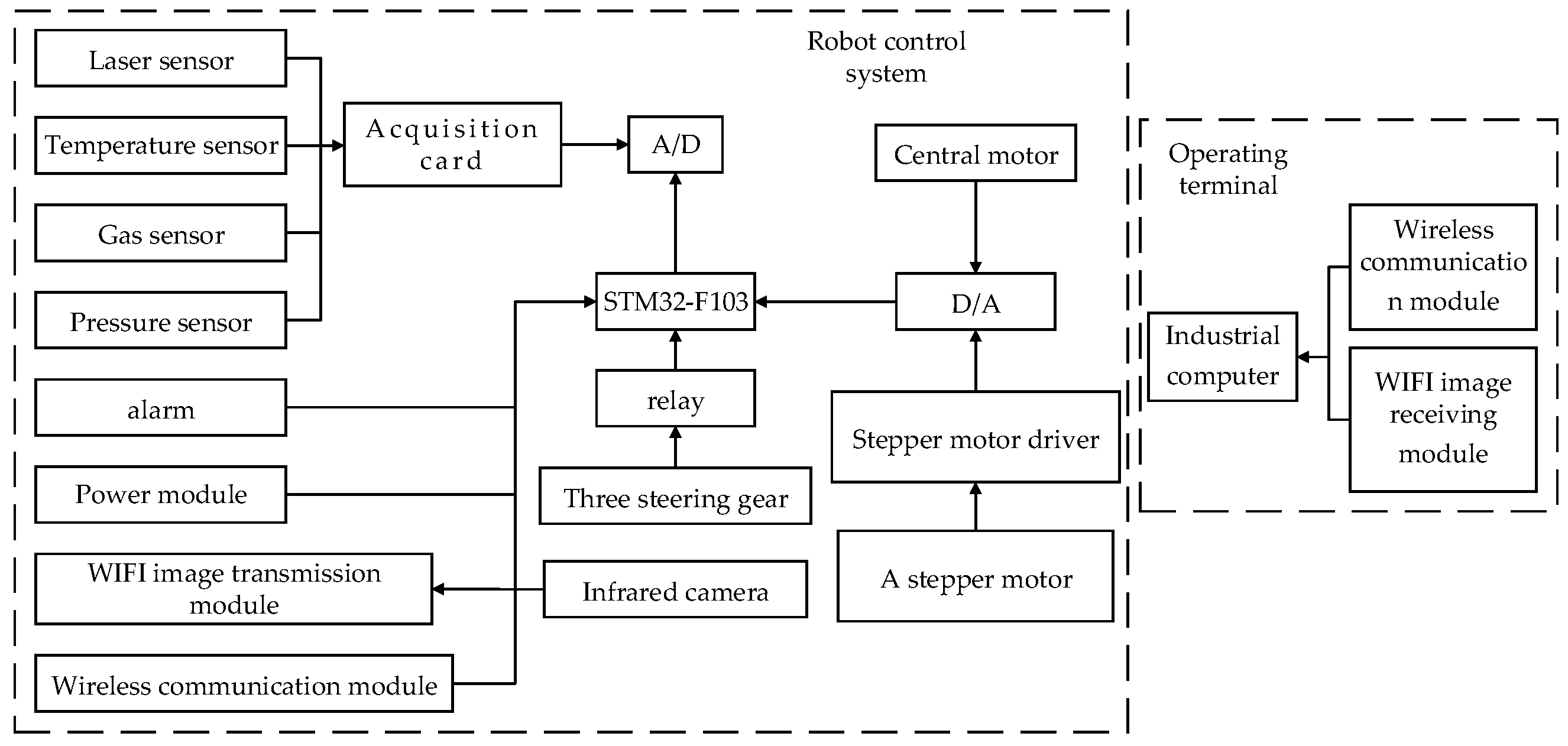
Figure 6 presents the control system of the pipeline inspection robot. The robot’s CPU is an STM32-F103 chip, while the console utilizes an embedded industrial computer. The pipeline inspection robot communicates with the industrial computer via wireless communication, and the robot CPU directs the robot to operate within the pipeline based on the commands provided by the operator using the industrial computer. Additionally, the robot performs defect detection and information collection functions within the pipeline.
The robot control system encompasses the robot motion control unit, the pipeline information acquisition unit, and the wireless communication unit. The pipeline information acquisition unit collects images and environmental data from within the pipeline. Image information includes defects such as cracks, leakages, pits, and corrosion. Image acquisition is achieved through two infrared night vision cameras with autofocus capabilities, positioned at the front and rear of the robot.
The front camera rotates and continuously scans around the pipeline’s axis during the robot’s spiral advancement, capturing defect information in the dark pipeline environment and fulfilling the 360° detection requirements for the pipeline’s inner wall. The rear camera supports the robot’s navigation and positioning functions within the pipeline, continuously outputting and storing images in real time. The collected environmental information encompasses gas concentrations, pipe diameters, and pipe temperatures.
The robot motion control unit governs the deflection angle of the three steering motors and the speed of the stepper motor and the central motor, adjusting the robot’s posture, speed, and bending mode while operating in the pipeline. Pressure sensors measure the pressure between the driving wheel and the pipeline’s inner wall, and the error value between the current pressure and the target pressure for the specific application is calculated. This error signal serves as the output signal for PID control, directing the central motor to adjust the positive pressure in order to achieve the desired robot traction force and improve the robot’s working efficiency within the pipeline.
Pipeline robots employ visual positioning methods within pipelines, utilizing images and point cloud data gathered by front and rear cameras, as well as laser ranging sensors, to ascertain the robot’s position and orientation within the pipeline. The process involves several specific steps: (1) data collection: images and point cloud data are collected by the robot’s cameras and laser ranging sensors; (2) feature extraction: the scale-invariant feature transform (SIFT) algorithm is employed to extract relevant features conducive to positioning, such as pipeline defects; (3) feature matching: the extracted features in the current image or point cloud data are matched with previously collected data or features in a pre-constructed map; (4) motion estimation: by matching pairs of feature points, the relative motion of the robot between two instances can be estimated; and (5) fusion and optimization: the estimated motion information is integrated into the robot’s positioning system, along with data from other sensors, such as odometers and inertial navigation systems.
Wireless communication leverages radio frequency (RF) technology to facilitate data transmission between pipeline robots and ground control centers. Utilizing specific frequency bands and modulation modes, low-frequency RF signals can minimize signal attenuation in underground environments. Low-frequency signals experience relatively less loss when penetrating underground structures, thereby enhancing communication distances. In the communication between pipeline robots and ground control centers, multiple antennas are installed on both the robots and the control stations to transmit signals simultaneously across multiple channels. This can counteract, to some extent, the multipath effect (where communication signals in underground environments may reflect, refract, and scatter within the pipe) and signal attenuation (as wireless signals experience attenuation when passing through underground structures). Signal attenuation is particularly pronounced when traversing metal, water, or other high-density materials, resulting in limited communication distances. Employing relay nodes for segmental signal transmission can increase communication distances and signal coverage. In pipeline robot-to-ground communication, multiple relay nodes are deployed to enable multi-hop transmission. When direct communication is hindered by signal attenuation and environmental obstacles, signals can be transmitted sequentially through relay nodes, allowing for longer-distance and more reliable communication.
2.3. Design of PID System for Pressure Regulation
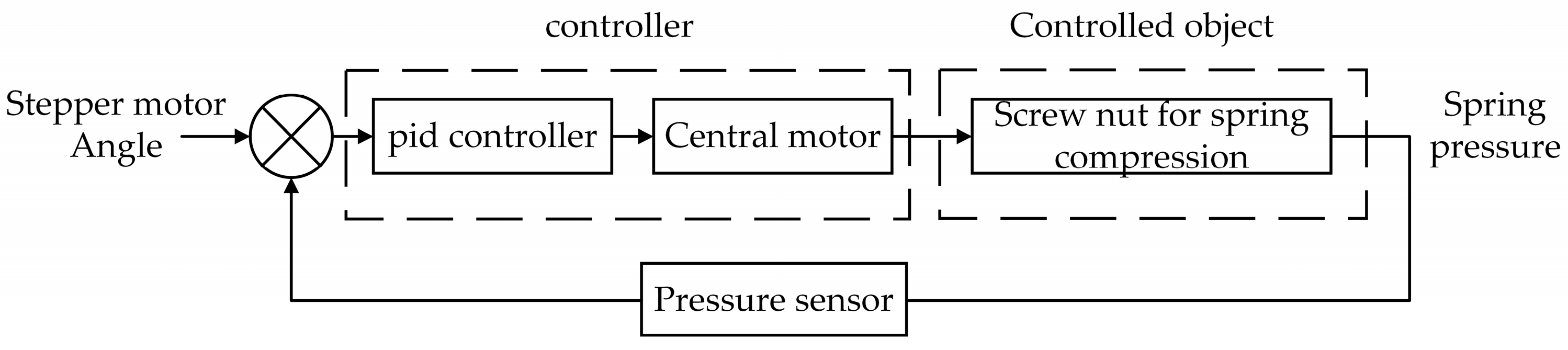
The PID control principle is shown in
Figure 7. The PID control system comprises the following components: a stepper motor, a lead screw nut, a spring, and a pressure sensor. The stepper motor controls the movement of the lead screw nut by adjusting the number of steps, thereby altering the compression of the spring and generating the corresponding elastic force. Simultaneously, the pressure sensor is utilized to measure the actual level of elastic force exerted by the spring. Assuming that the spring stiffness is
k, the damping coefficient is
b, the lead of the screw nut is
, and the angle of the stepper motor is
, then the displacement
of the screw nut can be expressed as:
The spring force
F(
t) can be expressed as:
The transfer function
of the system composed of a screw nut and a spring can be obtained by means of the Laplace transform:
The stepper motor transfer function is simplified to a first-order inertial system,
Km is the angle coefficient of the stepper motor,
T is the time constant of the stepper motor, and the transfer function is:
The whole system transfer function is:
The transfer function of the PID controller is:
By repeatedly adjusting the parameters , and of the three links, the PID control system with a fast response and small steady-state error can be obtained.
4. Influencing Factors and Simulation Analysis of Robot Traction Performance
A prototype model was created using ADAMS simulation software. The robot was imported into ADAMS, and its structure was simplified by retaining only the components associated with the transmission. This process led to the final establishment of the virtual prototype model for the pipeline robot.
4.1. Influence of Different Materials on Traction Performance of Robot in Straight Pipe Operation
The material used for oil pipelines is typically stainless-steel composite steel pipe, which is generally coated with an anti-corrosive layer on the inside, providing good corrosion resistance. Gas pipelines, on the other hand, are primarily made from steel, aluminum, or plastic pipes. Consequently, the traction force exerted by the pipeline robot varies depending on factors such as the transportation medium, transportation pressure, and pipe material. As demonstrated earlier, the traction force of the pipeline robot relies on the friction force between the driving wheel and the inner wall of the pipeline. This study investigates the difference in traction force for the pipeline robot under various working conditions and analyzes the magnitude of the traction force by simulating and altering its contact friction coefficient.
The traction force acting under different working conditions was simulated in ADAMS. First, the optimal spiral angle was set to 40°, and the contact force parameters between the driving wheel and the inner wall of the pipeline were established. The working condition refers to the operating state of the robot in various environments. Material 1 and Material 2 represent the materials of the driving wheel and the pipeline, respectively, and the stiffness coefficient K is 2855. The force index e is 1.1; the damping c is 0.57; the penetration depth d is 0.1; mus denotes the coefficient of static friction, while mud represents the coefficient of dynamic friction; v
s is the static translation velocity; and v
d corresponds to the friction translation velocity. Additional simulation parameters for different working conditions are presented in
Table 2 below. The pipe diameter is set at 200 mm, and the robot’s running time is 5 s.
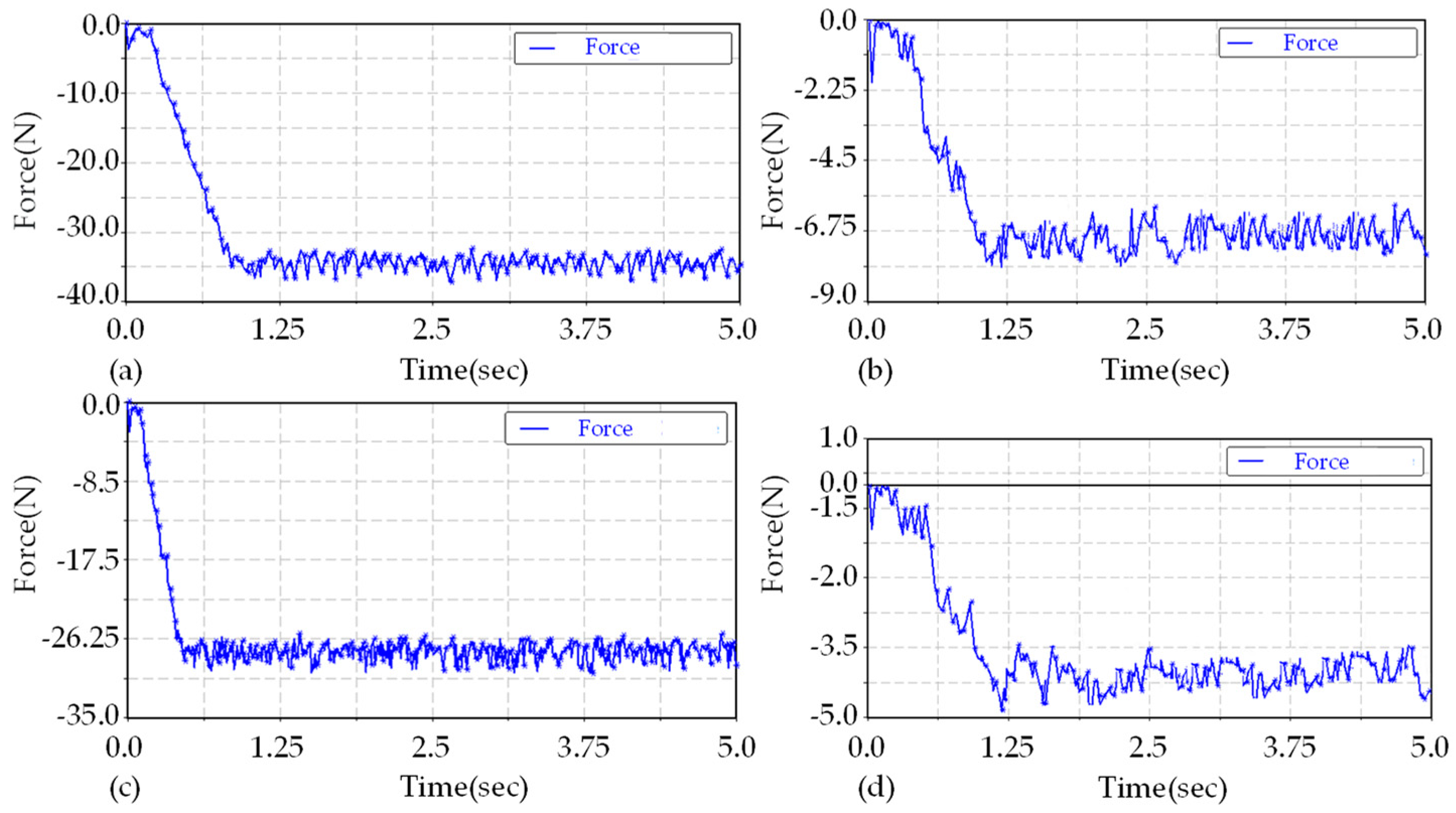
In the ADAMS simulation process, the traction force of the robot in operation can be simulated by placing a tension spring between the pipeline robot and the pipeline. The tension and compression spring is positioned on the pipeline axis. One end is connected to the robot’s center, and the other end is connected to the center of the vertical plane passing through the pipeline axis. The spring’s stiffness coefficient is set to 800, and the damping coefficient is set to 0.5. The simulation results of traction force in a straight pipe are shown in
Figure 11 below.
According to the simulation results, the tension of the tension spring in the four simulated operating conditions in the straight pipe will slip as the robot accelerates to its maximum speed. The maximum traction of the robot will fluctuate within a small range, and the traction will increase with the friction coefficient. The difference in the transportation medium within the pipe made from the same material will also impact the traction force. The tractive force of the robot running in a pipeline without a transport medium is significantly greater than that in a pipeline containing a medium.
4.2. Influence of Positive Pressure on Traction Performance of Robot Support Wheel
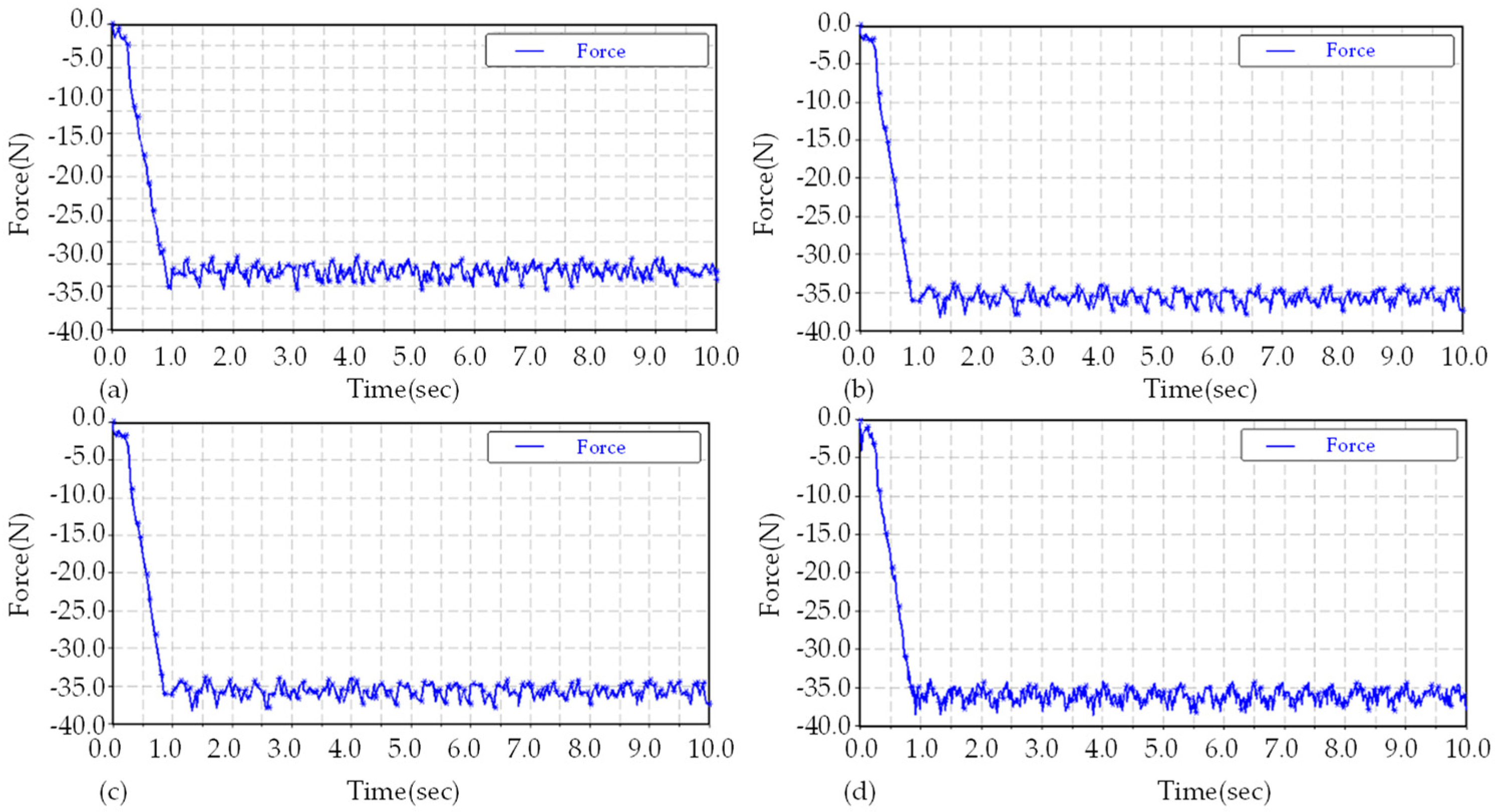
The pipeline robot is designed with three groups of supporting wheels, distributed at a 120-degree circumference, and each supporting wheel has a normal pressure with the inner wall of the pipeline. The appropriate normal pressure is crucial for the robot’s performance. Excessive normal pressure will result in high power consumption, while insufficient positive pressure will prevent the robot’s driving wheel from generating enough friction with the pipeline’s inner wall. In the analysis of normal force, the pipeline was set with no medium transport, the material was plexiglass, the coefficient of static friction was 0.2, the coefficient of dynamic friction was 0.15, and the simulation time was 10 s.
The normal force of the driving wheel was set at 100 N, 110 N, 120 N, and 130 N, respectively, and the simulation results met the requirement of traction force greater than 30 N, as shown in
Figure 12 below. The tractive forces were 33 N, 36 N, 38 N, and 38 N, respectively. The traction of the driving wheel increases with the increase in positive pressure. However, when the positive pressure reaches a certain value, the traction will no longer increase, because the robot’s maximum load capacity has an upper limit, ultimately causing the robot to become stuck in the pipeline and unable to function normally. Consequently, the normal force should be controlled between 100 N and 120 N, ensuring that the robot can run smoothly in the pipeline while consuming less power.
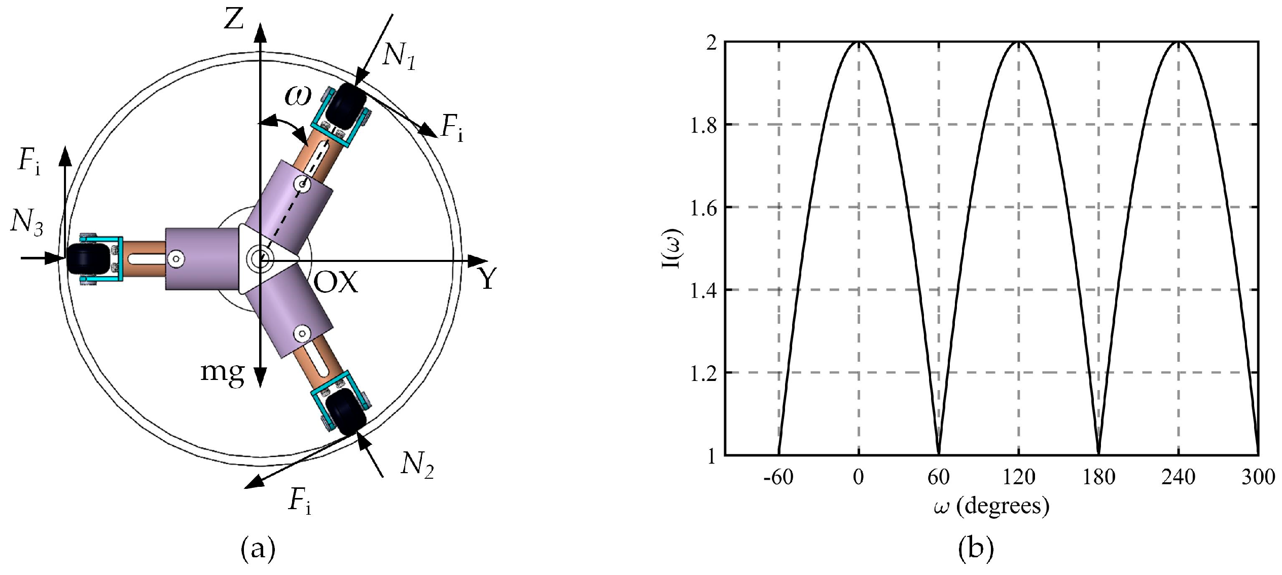
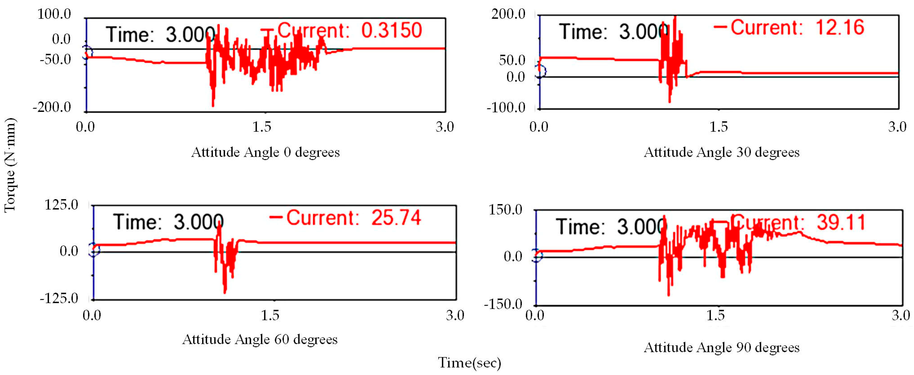
4.3. Analysis of the Influence of Robot Attitude Angle on the Rotation of the Support Unit
When the spiral pipeline robot travels within a pipeline, its spiral module rotates around the pipeline axis, while the support module serves to balance the counter torque generated by the spiral module. Consequently, the robot not only moves forward and backward inside the pipeline but also rotates around the pipeline axis, resulting in a change in the robot’s motion posture that deviates from its initial position. The support module is distributed circumferentially at 120-degree intervals. Although deviations in the robot’s motion posture do not impact its operation, it must maintain the optimal posture for entering bends as it navigates them. Furthermore, during the operation of the robot’s towing cable module, posture deviations can cause the cable to become entangled, necessitating limits and corrections to the robot’s posture deflection.
Based on the analysis in
Section 3.2, different attitude angles affect the robot’s torque. Therefore, four representative attitude angles of 0°, 30°, 60°, and 90° were selected for further examination. The simulation results are shown in
Figure 13. In the 0–90° attitude angle range, the support module’s rotational torque increases gradually with the rising attitude angle. When the attitude angle reaches 90°, the torque is at its maximum, and when the angle is 0°, the torque approaches zero. By adjusting the robot’s attitude angle to 0 degrees and maximizing the positive pressure between the support unit and the pipeline’s inner wall, the torque of the robot’s support unit can be reduced, effectively restraining the support unit’s rotation along the pipeline axis.
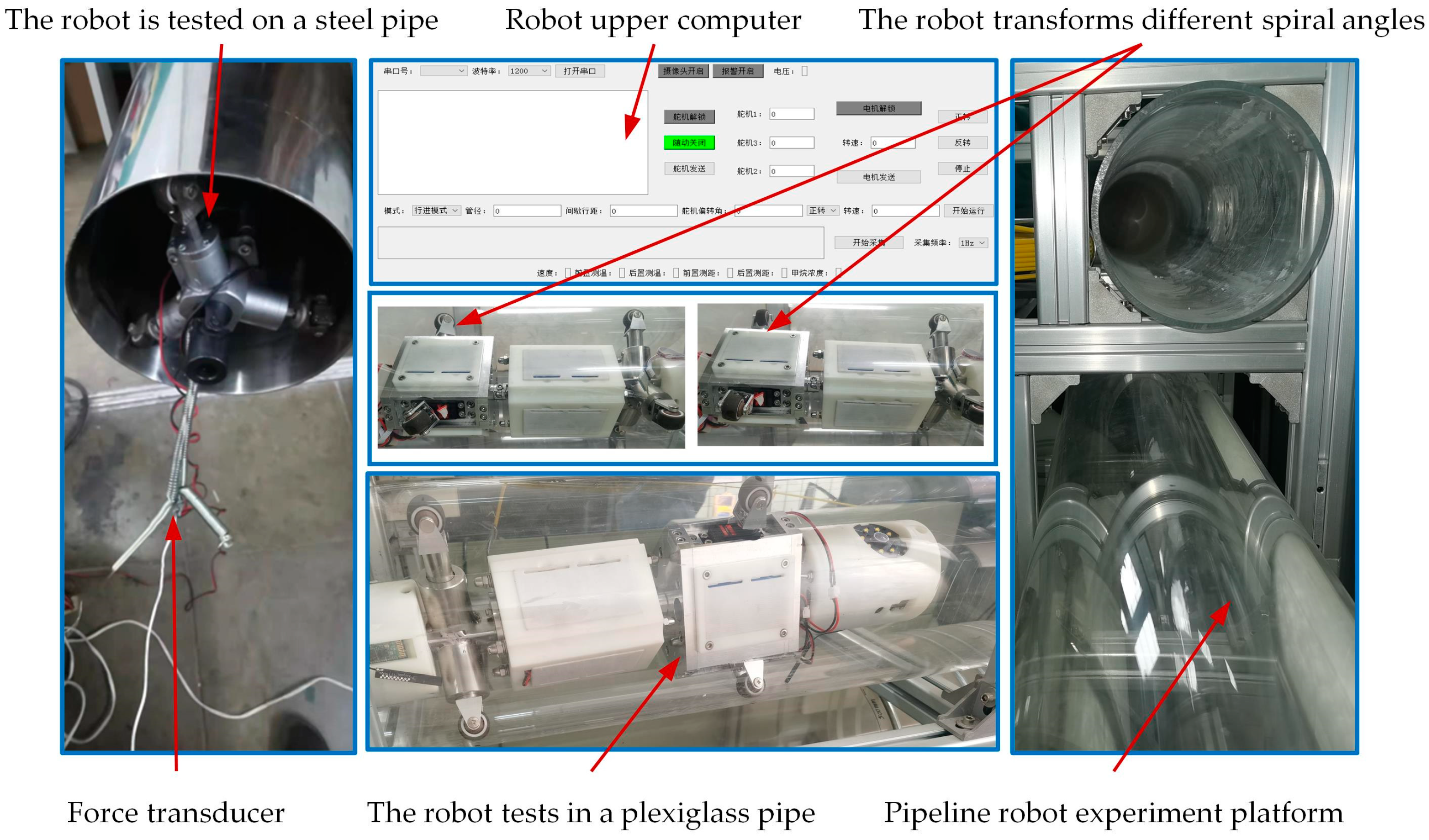
5. Traction Experiment Verification and Analysis
An experimental platform was constructed for the pipeline robot. As shown in
Figure 14, one end of the spring is attached to the pipeline robot, while the other end is connected to a force sensor. The sensor remains fixed in a specific position, and the robot initiates its operation within the pipeline. This setup enables researchers to systematically analyze the performance of the robot under various conditions, optimizing its design for maximum efficiency and functionality.
In this experiment, steel and plexiglass pipes are utilized as materials. Industrial lubricating oil is applied to simulate the conditions of a medium under actual operation. During the robot’s operation, when a slip occurs, the force sensor will cease data collection. The tractive force of the robot is influenced by factors such as normal force, spiral angle, pipe contact, and motor driving force. The spiral angle, pipe material, and driving wheel normal force were chosen as variables, with the peak value collected by the sensor being considered as valid data. A 42-series motor (the drive motor in the drive module of the robot) was employed as the driving motor for the robot prototype, and the torque was set at 10 Nm.
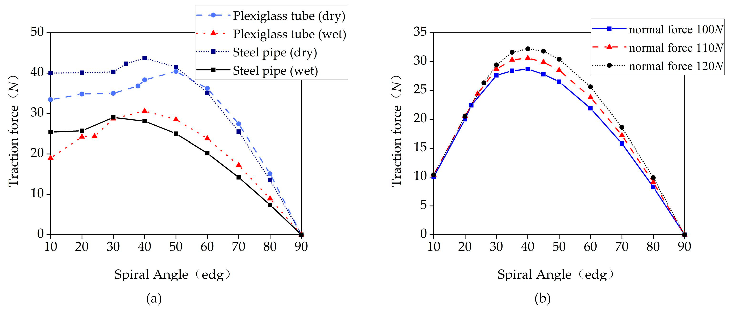
The test results are displayed in
Figure 15a, and the trend of traction force variation is generally consistent with the theoretical analysis. The traction force initially increases and then decreases with the increase in the spiral angle; however, there is a significant deviation from the theoretical analysis under conditions with small spiral angles. In sections with small spiral angles, the pipe wall cannot provide sufficient friction, making it prone to slippage and unsmooth operation. As the spiral angle increases, the slippage gradually disappears.
Among the four experimental working conditions, the steel pipe (dry) has the largest friction factor, and the optimal spiral angle is approximately 40°, followed by the plexiglass pipe (dry), with its optimal spiral angle at around 50°. Therefore, the optimal spiral angle for robot traction tends to increase as the friction factor decreases. Consequently, the robot’s spiral angle should be set based on different working conditions and varying spiral angles. The tractive force of running in a steel pipe (dry) is greater than that of running in a plexiglass (dry) pipe.
In the steel pipe (dry) condition, the robot operates with a large traction force due to its relatively high friction factor. The higher the friction factor, the greater the traction force. In pipelines made from the same material, the tractive force of the robot’s operation in a pipeline with a transport medium is significantly lower than in a pipeline without a transport medium.
In the experiment, the robot’s experimental working condition was set as a plexiglass pipe, and three different values of 100 N, 110 N, and 120 N were established by adjusting the normal force of the driving wheel. The normal force was monitored using a drive wheel pressure sensor, and each peak traction was recorded as a data collection point during the test. The test results, shown in
Figure 15b, exhibit the same variation trend as the simulation, although they are smaller than the simulation value. Under the same working conditions, the optimal spiral angle of the robot is approximately 40 degrees, and the optimal spiral angle does not change as the normal force increases.


 ,
, 


