Article

A New Performance Optimization Method for Linear Motor Feeding System

1
School of Mechanical Engineering, Hebei University of Technology, Tianjin 300130, China
2
Key Laboratory of Hebei Province on Scale-Span Intelligent Equipment Technology, Hebei University of Technology, Tianjin 300130, China
3
World Transmission Technology (Tianjin), Intersection of Gaoxin Avenue and Jingming Road, Beichen Science Park, Tianjin 300130, China
*
Author to whom correspondence should be addressed.
Actuators 2023, 12(6), 233; https://doi.org/10.3390/act12060233
Submission received: 24 April 2023 / Revised: 29 May 2023 / Accepted: 1 June 2023 / Published: 6 June 2023
(This article belongs to the Section Control Systems)

Abstract

:
The linear motor feeding system is a typical electromechanical coupling system. Conventional characteristic analyses of electromechanical coupling often overlook the influence of flexible deformation in critical components of the linear motor feeding system. Moreover, when employing genetic algorithms to optimize servo system PID control parameters, slow convergence, nonconvergence, or premature convergence problems may arise. To address these issues, this paper proposes a new performance optimization method for a linear motor feeding system. The method uses a combination of “multi-body theory + finite element” to accurately account for the flexible deformation of critical components of the feeding system, establishes a rigid–flexible electromechanical coupling model of the linear motor feeding system, and optimizes the PID parameters of the established model with an improved adaptive genetic algorithm. Simulation results demonstrate that, when utilizing an adaptive genetic algorithm to optimize the rigid–flexible electromechanical coupling model and a control system model that disregards flexible body deformation, the system achieves stability in 0.02 s and 0.027 s with overshoots of 13% and 27%, respectively. These outcomes confirm the accuracy and importance of considering flexible body deformation in the optimization performance of a linear motor feeding system. At the same time, the time required to reach the steady state of the rigid–flexible electromechanical coupling model optimized by the adaptive genetic algorithm is shortened from 0.035 s to 0.02 s. The sinusoidal signal response curve of the optimized system does not exhibit any peak overshoot compared with that of the nonoptimized system, and the response speed is also faster. These results demonstrate the effectiveness of the rigid–flexible electromechanical coupling model optimized by the nonlinear adaptive genetic algorithm. The displacement response curves of the linear motor feeding system under different workbench loads are obtained through experiments and compared with those obtained from simulations to verify the established model and the correctness of the proposed method.

1. Introduction

The linear motor feeding system is a crucial element of CNC machine tools, and its performance has a significant impact on the accuracy and quality of machining. As it eliminates the intermediate drive link, it has high positioning accuracy and fast dynamic response speed, which enables high-speed feed and is widely used in high-speed and high-precision motion occasions [1,2,3]. However, elimination of the intermediate drive link causes new problems. The linear motor mover is rigidly connected to the workbench and the disturbance forces act directly on the mover, resulting in the linear motor being sensitive to external disturbances. At the same time, heat and hysteresis caused by the loss of thrust, friction, two-axis load imbalance, and other factors lead to a tracking lag of the servo axes, and the dynamic characteristics of the axes do not match the larger error, thereby directly affecting the position tracking effect and control accuracy of the system. Therefore, it is important to optimize the performance of the linear motor feeding system.
The linear motor feeding system is a typical electromechanical coupling system with complex dynamics. The output feed displacement, speed, and acceleration affect the dynamic characteristics of both the mechanical system and the servo system. Moreover, changes in the servo output force characteristics affect the mechanical link, which further impacts the dynamic characteristics of the mechanical system. Thus, optimizing the performance of the linear motor feeding system requires a comprehensive understanding of both the mechanical and servo system dynamics. In the literature [4], the dynamics of the linear motor feeding system was modeled using Lagrange’s equation, the main mechanical vibration forms were analyzed, and then the effects of different mechanical vibration forms on the feeding system were investigated. Finally, the thrust spectrum characteristics of the linear motor feeding system considering mechanical vibrations were verified by experimental analysis. In the literature [5], the dynamic electromechanical coupling interaction between the feeding system and the drive motor was investigated. A circuit model of the asynchronous motor and an advanced structural hybrid model of the feeding system was developed, and based on this, the effect of the interaction between the drive motor and the mechanical system with given dynamic characteristics on the dynamic performance of the mechanical system was investigated. In the literature [6], a finite element method of numerical simulation combined with experimental measurements based on frequency response optimization was used to simulate the behavior of porous structures and to verify that porous structure fractions can improve the adaptive performance of automatic control systems for vibration damping applications in the low- and medium-frequency regions. In the literature [7], the D’Alembert formula was employed to model the dynamics of a linear motor feeding system. Through an analysis of the factors that impact the dynamic characteristics of the system, it was concluded that the mechanical link stiffness, servo control parameters of the servo control link, and feed speed collectively influence the mechanical dynamic characteristics of the system. A mechatronic modeling approach [8] has been proposed to address the impacts of the electromechanical coupling characteristics on the dynamic performance of the linear motor feeding system. The method investigated the nonlinearity of the drive circuit and the permanent magnet linear synchronous motor, by which an analytical expression was derived for the motor thrust. The mechanical dynamics were then modeled using Lagrange’s equation, with a discussion of the main forms of vibration. Finally, a mechatronic model was developed and experimentally verified. The results demonstrate that the proposed integrated modeling approach can accurately reflect the characteristics and dynamic accuracy of the linear motor feeding system, providing a theoretical basis for further understanding the electromechanical coupling phenomena and control compensation. In one study [9], the authors discuss how linear motor feeding systems lacking intermediate drive links are vulnerable to load fluctuations and internal and external disturbances, thereby impacting their positioning accuracy. To mitigate these issues, an optimization technique that employs a hybrid finite element method and PLS regression is proposed, which enhances the dynamic performance of the drive system by extending the nonresonant frequencies and improving the dynamics. In another study [10], the authors analyze the coupling process between the mechanical system and the servo system of a linear motor feeding system, focusing on the mechanism of electromechanical coupling that arises due to thrust harmonics. Their findings reveal that with the increase of the feed speed, the thrust harmonics cause significant displacement fluctuation. To address this issue, a comprehensive compensation method is proposed, through which the displacement fluctuation is reduced by more than 90%.
Previous studies have primarily focused on analyzing the electromechanical coupling characteristics of the feeding system, which is achieved by establishing an electromechanical coupling model of the linear motor feeding system and by investigating the dynamic characteristics and motion accuracy of the system. To enhance the motion and positioning accuracy, thus effectively enhancing the dynamic performance of the system, various compensation techniques have been employed. However, the problem of flexible deformation in critical components of the linear motor feeding system at high feed speeds, which reduces motion accuracy, is often disregarded.
In terms of servo control links, control systems generally use PID control, sliding mode control, adaptive control, active immunity control, and intelligent control [11,12,13,14,15]. PID control is a well-established and widely used control method, known for its simplicity, robustness, and reliability. As such, it is frequently utilized in servo control systems for CNC machine tools. However, linear motor feed servo systems are characterized by their time-varying and nonlinear behavior, making it difficult to determine PID control parameters directly. Thus, it is crucial to develop optimization methods for adjusting the control parameters of the position, current, and speed loops. By adjusting these parameters, the dynamic and static response characteristics of the feed servo system can be effectively improved, thereby enhancing the anti-interference ability and servo stiffness of the linear motor feeding systems. In one study [16], the bandwidth of the frequency response of the control system is used as the basis for optimizing the control parameters. The control parameters of the individual rings of the feed servo system of the two-axis CNC machine tools are sequentially adjusted from the inner ring to the outer ring, with the aim of maximizing the system bandwidth while maintaining stability. However, this method has some limitations, such as the requirement for constant adjustment of the control parameters and calculation of the frequency response, which can be time-consuming and less efficient. Moreover, it ignores the mutual influence of the control loops, making it difficult to obtain a globally optimal solution for the control parameters. Genetic algorithms are abstracted from the biological evolution of nature and are global probabilistic search algorithms based on processes such as natural selection and genetic variation. As a widely used optimization method, it has been applied to the solution of various optimization problems and has also been studied and applied by some scholars in PID parameter optimization problems. One study [17] proposes the use of genetic algorithms to optimize the PID parameters offline for electrohydraulic servo systems driven directly by permanent magnet synchronous motors. The step response characteristics of the system were simulated and then experimentally tested, which demonstrates that the optimized PID controller using the genetic algorithm exhibits strong dynamic performance. Hao et al. [18] present the use of a genetic algorithm to optimize the parameters of a ball screw-type feed servo system for parallel machine tools, including the velocity loop scale factor, integration time, position loop scale factor, integration time, and differentiation time. The performance improvement is evaluated by analyzing the step response, Bode plot, and circular motion trajectory. However, this approach does not take into account the effect of disturbances on the feed servo system during the calibration process, nor does it consider the thresholds and value ranges of the parameters. Liu et al. [19] apply the Nyquist criterion to determine the stability region of each PID controller parameter in a control model of feed servo system, and the errors in the recovery process are also considered after being subjected to disturbing forces. A genetic algorithm is then used to jointly adjust the velocity and position loop controller parameters based on the evaluation criteria. However, the current loop is not included in the scope of the joint rectification, which may lead to suboptimal performance. The above-mentioned scholars’ research fully illustrates the rationality and feasibility of genetic algorithms in the optimization of control system PID parameters, but there are also some problems, such as the slow convergence and poor optimization effect in the optimization process of traditional genetic algorithms.
The optimization methods mentioned earlier for linear motor feeding systems have certain limitations. For example, they may overlook the effect of flexible deformation of key components or suffer from slow convergence or premature convergence of the genetic algorithm. To address these issues, this paper proposes a novel approach to optimize the performance of the linear motor feeding system. Specifically, a rigid–flexible electromechanical coupling model of the feeding system is developed, which takes into account the flexible deformation of key components using a combination of multibody theory and finite element analysis. Moreover, the genetic algorithm is improved with nonlinearly varying adaptive crossover probability and variance probability to enhance convergence speed and accuracy. The improved genetic algorithm is then employed to optimize the PID control parameters of the rigid–flexible electromechanical coupling model control system, leading to improved motion accuracy, dynamic characteristics, and interference immunity of the linear motor feeding system.

2. Rigid–Flexible Electromechanical Coupling Model for Linear Motor Feeding System

2.1. Complexity Analysis of Permanent Magnet Synchronous Linear Motor Feeding Systems

This study focuses on the X-Y two-axis linkage linear motor feeding system, which employs a permanent magnet synchronous linear motor (PMSLM) as the driving component to achieve high-speed and high-precision trajectory movement. The X and Y axes are arranged orthogonally, and the structure is depicted in Figure 1. The stator of the linear motor is fixed to the machine tool, and the mover is rigidly connected to the workbench. The movers of both axes are coupled and generate electromagnetic thrust upon applying an electric current. This, in turn, propels the rigidly connected workbench along the guideway to enable linear movement in the feed direction.
The linear motor feeding system, lacking an intermediate transmission link, is highly susceptible to external disturbances such as cutting forces and thrust harmonics. These disturbances directly act on the motor mover, causing electromagnetic thrust and displacement fluctuations that impact the motion accuracy and dynamic characteristics of the system. Moreover, the feed displacement, speed, and acceleration at the output of the system affect not only its dynamic behavior but also the characteristics of the servo drive link. In turn, any changes in the servo output force can alter the mechanical link and, consequently, the dynamic behavior of the system [20]. The strong coupling relationship between the mechanical and servo systems, combined with their nonlinearity and time-variability, creates a complex and challenging control problem, as illustrated in Figure 2.
When it comes to high-speed and high-precision feeds, the flexible deformation of the feeding system can have a significant impact on its dynamic characteristics. The flexible deformation of crucial components such as the workbench and linear guides has an even more pronounced effect on the overall performance of the feeding system. The dynamic characteristics of the entire system are influenced by both the elastic deformation of key components and the time-varying, nonlinear, and electromechanical coupling characteristics in the feeding system. Moreover, interactions between these factors increase the dynamics and unpredictability of the system [21]. Using traditional rigid body assumptions to analyze the mechanical system of a linear motor would result in significant errors. Therefore, it is essential to consider flexible body deformation in establishing the rigid–flexible electromechanical coupling model of the linear motor feeding system.

2.2. Rigid–Flexible Coupling Model of Linear Motor Feeding System

The linear motor mechanical feeding system comprised both rigid bodies and flexible bodies. The motion of rigid bodies can be analyzed and calculated using the theory of multirigid body dynamics, while the motion of flexible bodies with large deformations can be analyzed using the dynamics of a multiflexible body system. The modelling process of the rigid–flexible coupling model is illustrated in Figure 3. First, a three-dimensional model of the flexible component is established, and then it is imported into the finite element analysis software ANSYS to output the modal neutral file after flexible processing. Finally, the generated modal neutral file is introduced into ADAMS to establish a connection between the rigid body and the flexible body, resulting in the creation of the model.

2.2.1. Rigid Body Modelling of Linear Motor Feeding Systems

To create the rigid body model of the linear motor feeding system, a SolidWorks 3D model is imported into ADAMS and the appropriate material properties are assigned. Then, relevant constraints, forces, and other conditions as needed are applied as shown in Figure 4.

2.2.2. Flexible Body Handling of Key Components of Linear Motor Feeding Systems

After analyzing the key components of the rigid body model using ANSYS finite element analysis software, it is determined that the flexible deformation of the guide rail and workbench has a significant impact on the overall performance of the feeding system. Therefore, the guide rail and workbench are modeled as flexible bodies while other parts are modeled as rigid bodies. The guide rail and workbench are meshed using ANSYS APDL, and finite element analysis is conducted to establish the rigid area of the connection between the flexible body and rigid body parts. Finally, a modal neutral file containing modal information is generated, which represents the flexible body file, as depicted in Figure 5.

2.2.3. Determination Method of Joint Parameters

The feeding system joint is modeled as a spring-damped flexible connection, as depicted in Figure 6. The coordinate origin is taken as the center of mass of the workbench and the mover, with the flexible connection between the workbench and the guide simplified as a spring-loaded damping system in the Y and Z directions and a separate damping system in the X direction. The overall mass of the system comprises the mass of the table and the motor, while the stiffness is determined by the servo stiffness (primarily acting on the motor and proportional to the proportional gain of the servo system) and the tangential and normal stiffness of the contact between the guide and the slider. It is worth noting that the differences between individual sliders are ignored. Each slider is subject to damping in the X, Y, and Z directions, with the damping units acting on the center of the slider. It is assumed that the distance between the center of mass of the slider and the workbench and mover in the Z direction is negligibly small.
The joint dynamics model is established by using a spring-damped flexible joint and the parameters of the joint surface are determined using the Masataka Yoshimura method [21]. The equations for the vertical and horizontal vibrations of the system are given as:
M x ¨ + c x ˙ + k x = f ( t )
z ( s ) f ( s ) = 1 M ( s 2 + 2 ξ ω r s + ω r 2 )
Therefore, the contact surface stiffness is K = 4 M π 2 f r 2 , the damping ratio is ξ = ( f 2 f 1 ) / 2 f r , and the damping is c = 4 M π 2 f r 2 ξ , where f 1 and f 2 are the frequency corresponding to the half-power points and f r is the intrinsic frequency. The joint parameters of the guide can be calculated accordingly and are shown in Table 1.
The parameters of the joint surface between the workbench and the slider can be obtained using the Masataka Yoshimura method, and the contact stiffness in the direction perpendicular to the joint surface and parallel to the joint surface is obtained as 2.76 × 10⁶ N/m and 1.38 × 10⁵ N/m, respectively, and the damping is 138 N·s·m−1 and 163 N·s·m−1, respectively.

2.2.4. Rigid–Flexible Coupling Modeling of Linear Motor Feeding System

On the basis of a multirigid body dynamics model, the modal neutral files of the guide rail and workbench are imported and replaced. Constraints are established, and flexible connections are established using bushing elements. Based on the D’Alembert principle and Hertz contact theory, the parameters of the binding surfaces between various components are determined, and the binding surface parameters are set using flexible connections. The two are combined to establish a rigid–flexible coupling model with modal information in ADAMS, as shown in Figure 7.

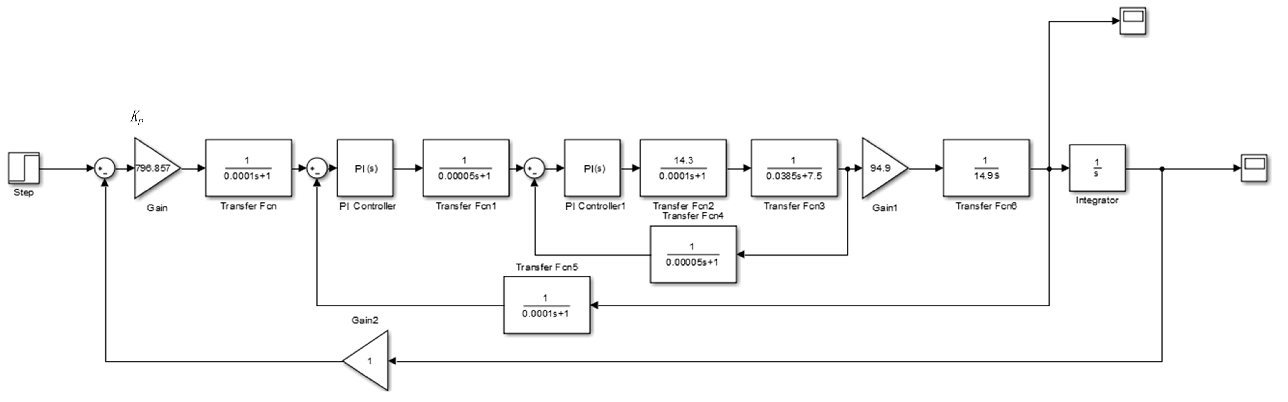
2.3. Linear Motor Feeding System Control Modeling

The control link of the linear motor feeding system adopts a triple-closed-loop control structure including current loop, speed loop, and position loop. The current loop uses a PI controller to improve the speed of the system and suppress internal disturbances in the current loop in time. The speed loop uses a PI controller to increase the resistance of the system to load disturbances and suppress speed fluctuations. The position loop uses a P controller to ensure the static accuracy and dynamic following error of the system for stable operation. The design of the three-loop structure and the quality of the controller directly affect the stability, accuracy, and speed of the entire servo system. The following premise assumptions are made for each of its link transfer functions, and then the control model of the linear motor feed servo system shown in Figure 8 is established.
The following assumptions have been made in this study:
(1)
The dynamic characteristics of the workbench along the feed direction have been considered, and for the purposes of simplification, the mechanical system has been modeled as a single inertia system.
(2)
In the interest of simplifying the analysis, the interpolation, acceleration, and deceleration effects of the control system have not been taken into account.
(3)
The system has been treated as a continuous system, disregarding any differences in calculation periods between the control loops.
(4)
The inverter has been approximated as a first-order inertial link.
Where the transfer function of the current loop PI controller is PI = K i ( 1 + 1 T i s ) , the transfer function of the velocity loop PI controller is PI = K v ( 1 + 1 T v s ) , the transfer function of the position loop P controller is P = K p , K i and T i are the gain and integration time of the current loop controller, respectively, K v and T i are the scale factor and integration time of the velocity loop PI controller, respectively, and K p is the proportionality factor of the position loop proportional controller. The values and meanings of the other parameters in the control model are shown in Table 2.
The Simulink simulation model of the linear motor feed control system in MATLAB based on the control system model and the parameters is shown in Figure 9.

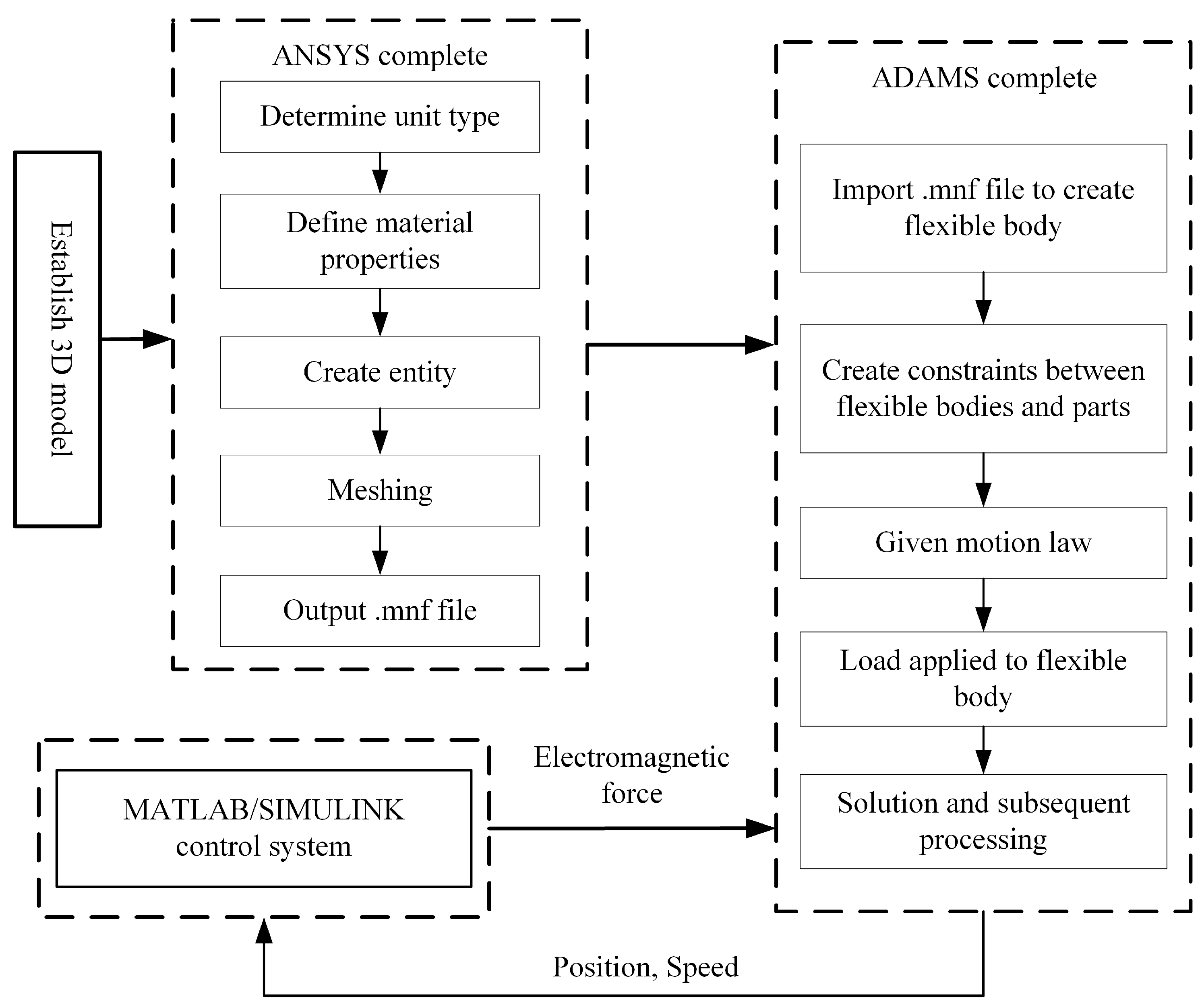
2.4. Rigid–Flexible Electromechanical Coupling Modeling of Linear Motor Feeding Systems

The previously established rigid–flexible coupling model and control model serve as the foundation for developing a rigid–flexible electromechanical coupling model of the linear motor feeding system. The modeling process is depicted in Figure 10.
A joint simulation of ADAMS and MATLAB is conducted based on the previously established rigid–flexible coupling model and servo control system using MATLAB/Simulink. During the simulation, both workbench displacement and velocity are outputted by the mechanical system and used as feedback inputs to the control system. Meanwhile, the control system outputs the electromagnetic force, which is utilized as an input to the mechanical system. Finally, data exchange is carried out through the data interface to realize the joint simulation. The resulting model is illustrated in Figure 11 and Figure 12.

3. Adaptive Genetic Algorithm

3.1. Basic Principles of Adaptive Genetic Algorithms

The genetic algorithm is a technique that simulates the natural mechanisms of biological genetic evolution to optimize and adjust parameters, using fitness as an evaluation criterion. The basic idea behind the genetic algorithm is to generate and encode a population of individuals. These individuals are then selected by the fitness function, and new individuals are generated by replication, crossover, and mutation operations. The iterative process continues until the optimal solution is obtained and the optimization objective is achieved. The traditional genetic algorithm adopts a fixed crossover rate and variation rate, which has suitable robustness for solving general global optimization problems. However, it may suffer from issues such as “premature convergence” or slow convergence speed when synchronously optimizing control parameters. Adaptive genetic algorithms differ from traditional genetic algorithms in that the crossover and variation probabilities are automatically adjusted based on the fitness function, which significantly improves computational efficiency and accelerates the convergence of the algorithm [22].

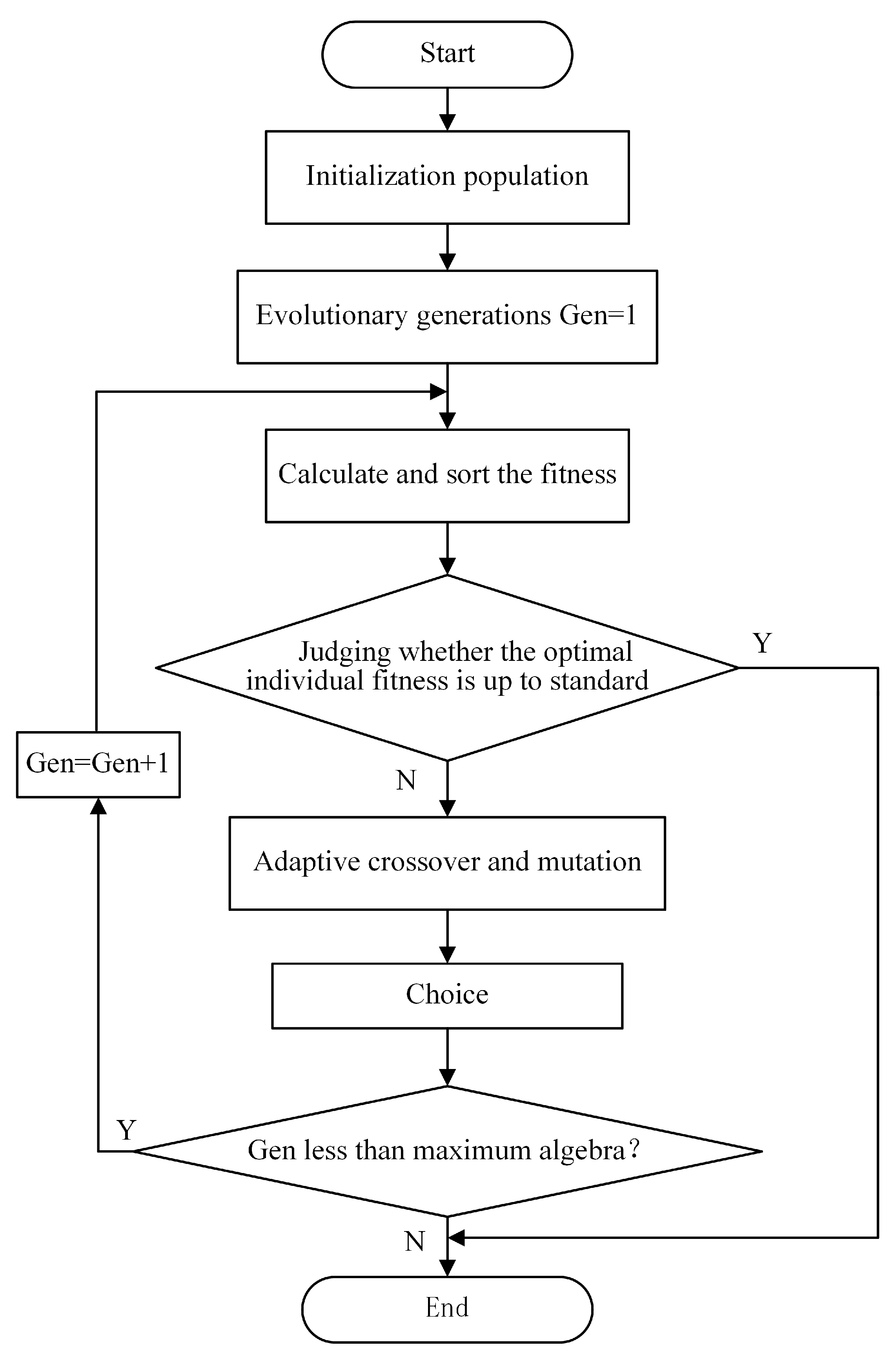
3.2. Adaptive Genetic Algorithm Optimization Steps

The basic flow of the adaptive genetic algorithm is shown in Figure 13. This includes coding, initializing the population, designing the fitness function, selecting the operation, designing the adaptive variation rate and crossover rate, crossover operation, variation operation, and the final convergence judgment. The specific implementation of the algorithm is roughly divided into the following six steps.
Step 1: Code the five PID control parameters to be optimized using real number coding to obtain the initial population.
Step 2: Combine the characteristics of the linear motor feed servo control system to design the adaptation function.
Step 3: Combine the designed fitness function to select the individuals with high fitness to be retained, and the individuals with low fitness to be replaced randomly.
Step 4: Combine the linear adjustment method and the Sigmoid function to balance the advantages of linearity and nonlinearity, and design the adaptive crossover rate and variance rate methods.
Step 5: Combine the designed adaptive crossover rate and variance rate methods to perform crossover and variation operations on the population individuals except for the optimal individuals and eliminated individuals.
Step 6: Judge whether the final optimal fitness value meets the criteria. If it does, output the optimized control parameter results, if not, continue the convergence iteration.

3.2.1. Coding

To improve the convergence speed and accuracy of the optimization solution of traditional genetic algorithms, expand the extended space search range, and to overcome the Hemming cliff problem caused by the binary encoding method, this paper adopts the real number encoding method [23,24] to directly encode the control parameters to be optimized. The control parameters to be optimized are K i , T i , K v , T v , and K p , which together form an individual E. This is shown in Equation (3), where g is the individual number.
E g = [ K i g , T i g , K v g , T v g , K p g ]

3.2.2. Initial Population Generation

The number of individuals in the population is set to N. The parameters of each individual are assigned randomly according to the range of values. The initial population KPID is generated as a matrix of control parameters for all individuals in the population, as shown in Equation (4).
K P I D = E 1 E 2 E N = K i 1 T i 1 K v 1 T v 1 K p 1 K i 2 T i 2 K v 2 T v 2 K p 2 K i N T i N K v N T v N K p N

3.2.3. Designing the Fitness Function

The fitness function is a criterion used in genetic algorithms to distinguish between strong and weak individuals in a population, and its design is a key factor affecting the optimization effect of genetic algorithms. Based on control requirements such as stability, accuracy, speed, and strong anti-interference capability of the control system, a composite evaluation index consisting of an error integration term (IAE), an overshoot penalty term, and a stability time term is chosen here as the fitness function of the genetic algorithm. As shown in Equation (5), where the error integration term is the time-integrated multiplicative weighting factor for the absolute value of the error of the system reaching a steady state from the initial state, the overshoot penalty term is obtained by integrating the square of the overshoot portion of the output signal and multiplying by the weighting factor, and the stability time term is the time-integrated multiplicative weighting factor for the system reaching stability:
F = 1 ω 1 0 t ( e ( t ) ) d t + ω 3 t u , u ( t ) R 1 ω 1 0 t ( e ( t ) ) d t + ω 2 0 t u + 2 ( t ) d t + ω 3 t u , u ( t ) > R
where e ( t ) is the difference between the output and input of the feed servo system, u + ( t ) is the output overshoot component, t is the simulation time, t u is the stabilization time, ω 1 is the error integration term weight factor, ω 2 is the overshoot penalty term weight factor, and ω 3 is the stabilization time term weight factor. After several simulations, it is found that the algorithm can achieve better results when ω 1 = 0.999 , ω 2 = 10 , and ω 3 = 1 . u ( t ) > R means that the output of the system is greater than the input at this moment.

3.2.4. Selecting Operations

After the fitness function has been determined, each individual is judged by the calculated fitness function value. Individuals with high fitness are retained, while those with low fitness are removed, and new individuals are generated.

3.2.5. Designing the Adaptive Variation Rate and Crossover Rate

The values of crossover rate and variation rate in traditional genetic algorithms are fixed, and the choice of crossover probability and variation probability directly affects the convergence of the algorithm. To avoid the choice of such fixed crossover and variation probabilities, the strategy of adaptive adjustment of crossover and variation probabilities has emerged. The convergence speed of the algorithm can be enhanced by introducing linear modifications to the crossover and variance rates [25]. However, there are still deficiencies in the local search capability of the algorithm and the spatial search range of the solution. To improve the diversity of suitable solutions, this paper introduces the Sigmoid function, which has the advantage of balancing linearity and nonlinearity [26]. The Sigmoid function is used to make adaptive adjustments to the crossover rate and variance rate. Individuals with higher fitness are adjusted according to their position in the overall population. Individuals with higher fitness have higher crossover probability and lower variation probability, which prevents crossover probability and variation probability from varying linearly. This prevents the destruction of the stronger individuals outside the optimal ones and improves the local search ability of the algorithm. The adaptive crossover rate and variation rate formulas obtained by introducing the Sigmoid function to improve the linearly varying crossover rate and variation rate approach are shown in Equations (6) and (7):
P c = P c m a x P c m i n 1 + exp ( A 1 ( F F a v g F m a x F a v g 1 2 ) ) + P c m i n , F F a v g P c m i n , F < F a v g
P m = P m m i n P m m a x 1 + exp ( A 2 ( F F a v g F m a x F a v g 1 2 ) ) + P m m a x , F F a v g P m m a x , F < F a v g
where A 1 = A 2 = 10 , F is the fitness of an individual, F a v g is the mean value of fitness, F m a x is the maximum fitness value, P c m a x is the minimum value of crossover probability, P c m i n is the maximum value of crossover probability, P m m i n is the minimum value of variation probability, and P m m a x is the maximum value of variation probability. The curve of the crossover rate P c and the variation rate P m as a function of the crossover rate are shown in Figure 14.
The adaptive crossover rate and variation rate have varying maximum and minimum values. The crossover rate and variation rate in the traditional genetic algorithm are the average values of those in the adaptive genetic algorithm. After running 100 repetitions with different parameter configurations, statistical analysis showed that the mean adaptation values obtained using the adaptive genetic algorithm (18.436) were better than those obtained using the conventional genetic algorithm with fixed variance and crossover rate (16.896), indicating that the adaptive genetic algorithm is more effective in finding strong individuals. The comparison of step response and fitness obtained by using the adaptive genetic algorithm and traditional genetic algorithm to optimize the PID parameters of the servo control system are shown in Figure 15 (the result of a single run of the program), which shows that the use of the adaptive genetic algorithm can avoid the algorithm falling into local convergence, and the final fitness value shows that the adaptive genetic algorithm has a stronger search ability.

3.2.6. Crossover Operations

Except for the best individual and the eliminated individual, the remaining individuals were ranked according to their fitness. Crossovers were performed in groups of two adjacent individuals according to the adaptive crossover rate of Equation (6) using a roulette wheel. The crossover is a single segment crossover (only one or several adjacent ones at any position are crossed).

3.2.7. Variation Operations

The value of the adaptive variation rate P m in Equation (7) is used to discriminate whether a gene is mutated or not. If a variation occurs, this control parameter is replaced with a randomly generated number in the range of values, otherwise the newly generated individuals are substituted into the next generation.

3.2.8. Convergence Judgement

The maximum fitness is compared with the target fitness. If the optimization objective is reached, the individual with the highest fitness is taken as the optimal individual, and the resulting control parameters are taken as the final optimization result.

4. Analysis of Simulation and Experimental Results

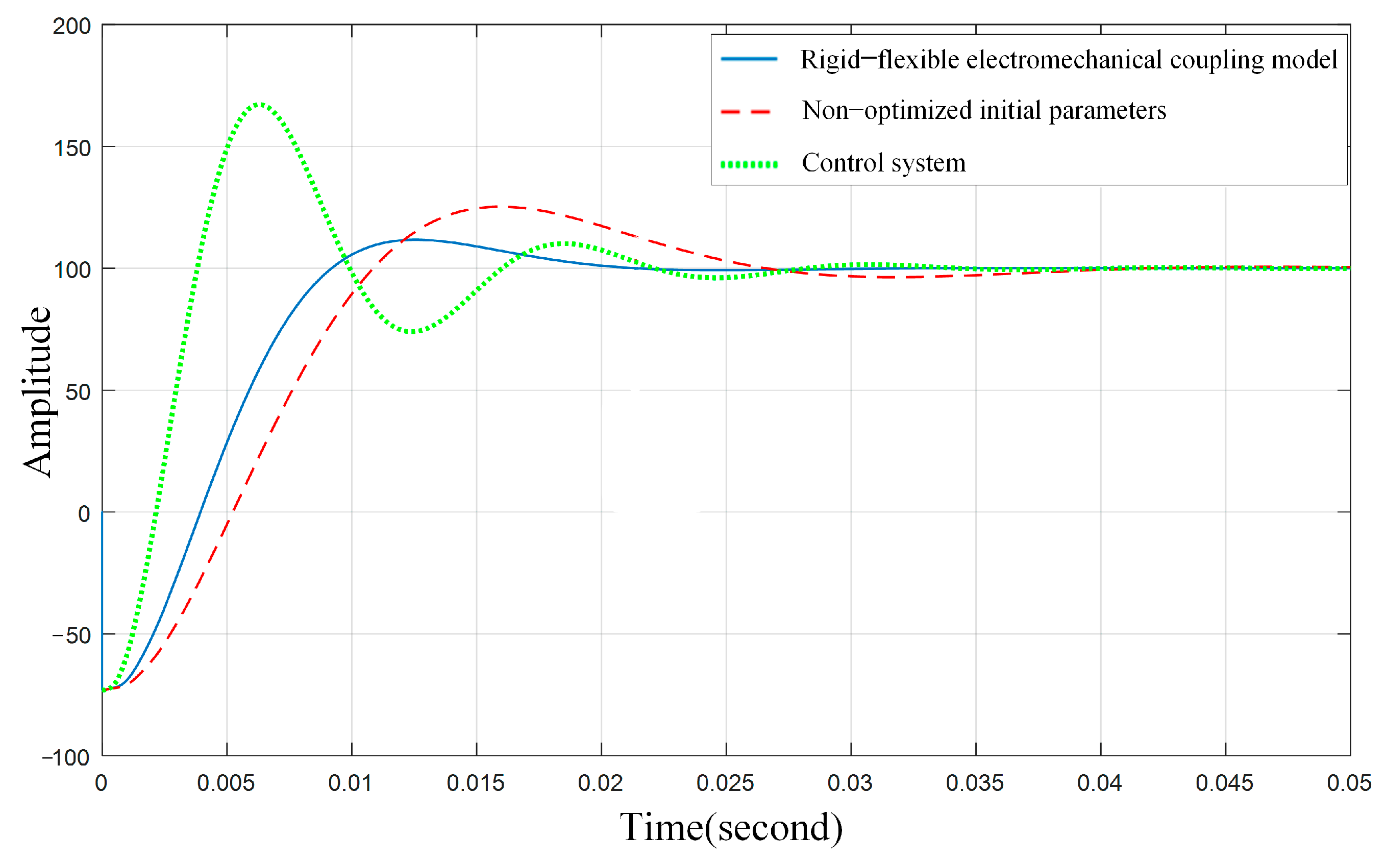
4.1. Simulation and Results Analyses

The control system model in Figure 9 and the rigid–flexible electromechanical coupling model in Figure 10 are optimized using an improved nonlinear adaptive genetic algorithm in a MATLAB simulation environment. The control parameters obtained by optimizing the rigid–flexible mechanical coupling model using the adaptive genetic algorithm, the control parameters obtained by optimizing the control system, and the control parameters of the control system that are not optimized by the adaptive genetic algorithm are shown in Table 3.
The three sets of control parameters obtained are substituted into the rigid–flexible electromechanical coupling model of the linear motor feed servo control system. The step response is simulated using MATLAB and the results are shown in Figure 16. The analysis shows that the stabilization times are 0.02 s, 0.027 s, and 0.035 s for the nonlinear adaptive-genetic-algorithm-optimized rigid–flexible mechanical coupling model, the optimized control system and the nonoptimized control system, with an overshoot of 13%, 69%, and 27%, respectively. The control parameters obtained by optimizing the rigid–flexible electromechanical coupling model through the adaptive genetic algorithm are more resistant to disturbances and more stable than those obtained by both nonoptimized and optimized control systems.
These three sets of control parameters are substituted into the electromechanically coupled Simulink simulation model shown in Figure 17. After applying a sinusoidal signal with a frequency of 25 Hz and an amplitude of 50 mm as input, the resulting output signal of the system is displayed in Figure 18. The results show that the nonoptimized system has a large sine signal following error and a significant peak overshoot; the response curve of the sine signal obtained by optimizing the control system has a faster response speed, but the peak of the response curve is overshoot. The system obtained by optimizing the rigid–flexible electromechanical coupling model with a non-linear adaptive genetic algorithm has no peak overshoot and exhibits a faster response speed. This optimized system meets the feeding requirements and demonstrates a superior optimization effect.

4.2. Experiments and Analysis of Results

An experimental platform is constructed to validate the precision of the rigid–flexible electromechanical coupling model for linear motor feeding systems. The platform includes an X-Y two-axis linked linear motor feeding system, a Renishaw XL-80 laser interferometer, a feeding system controller, a computer, and other supporting equipment, as shown in Figure 19 and listed in Table 4.
A feeding system with one feed axis of a two-axis linear motor motion stage is used as the object of study, and the displacement response of the system under different loads is experimentally investigated by using a Renishaw XL-80 laser interferometer. The principle of measuring the displacement of the feed axis direction with a laser interferometer is to dynamically obtain the displacement in the feed direction of the linear motor feed servo system through the laser. The laser linearly passes through the interferometer and is divided into two beams of light, each of which is reflected by a linear mirror fixed at a distance from the linear interferometer and a linear mirror fixed on the workbench, forming interference fringes in the interferometer, by measuring the changes in interference fringes, the displacement in the feed axis direction of the linear motor workbench can be obtained. The specific measurement process is to install the reflector on the workbench of the linear motor feed shaft, fix the interferometer on the marble platform as a linear mirror group, and then adjust the position of the mirror group according to the usage method of the laser interferometer to achieve beam collimation. Using a controller to control the motion of the feeding system, and using a laser interferometer to measure and record the displacement in the feed direction in real-time, the displacement response of the linear motor feed servo system under different loads is ultimately obtained. According to the load range and travel range of the motion platform, three loads (0 kg, 10 kg, and 20 kg) are added, and the servo command is input to displace the workbench by 100 mm. The experimentally obtained step response curves are compared with those obtained from simulations to verify the effectiveness of the model.
The rigid–flexible electromechanical coupling model of the linear motor feeding system is used to simulate the step response of the workbench displacement under different loads, and the simulation curve is shown in Figure 20. In addition, the data collected from the experiments are analyzed, and the response curves of the feeding system displacement in the feed direction under different loads are plotted as shown in Figure 21, which shows that the displacement response of the feeding system gradually becomes slower, and the vibration increases as the load increases. The difference between the simulated and experimental results is comparable. Although the time to stabilization is slightly shorter than the experimental results and the amplitude of the vibration is reduced compared to the experimental data, the pattern obtained from the simulation is consistent with that obtained from the experiments, demonstrating the correctness of the rigid–flexible electromechanical coupling model.

5. Conclusions

This paper proposes a new performance optimization method for linear motor feeding systems. Traditional electromechanical coupling models of linear motor feeding systems have limitations due to the neglect of flexible body deformations in key components, leading to low model accuracy. In order to solve this problem, a rigid–flexible electromechanical coupling model of a linear motor feeding system is established by using joint simulation technology, and an improved adaptive genetic algorithm is used to synchronize and optimize the three-loop PID parameters of the linear motor servo system, combining with the control requirements to determine the adaptation function, and a more reasonable nonlinear variation of the crossover rate and variation rate is used to operate on the individuals composed of five control parameters after the parameter optimization results are finally obtained through continuous iterations. The simulation and experimental validation of the optimization results lead to several conclusions.
(1) By utilizing the nonlinear adaptive genetic algorithm to optimize the three-loop PID control parameters of the rigid–flexible electromechanical coupling model, the time required for the system to reach a steady state is significantly shortened, resulting in a 42.8% reduction in stabilization time from 0.035 s to 0.02 s after optimization. This demonstrates the effectiveness of this algorithm for optimizing the model. Meanwhile, comparing the nonlinear adaptive-genetic-algorithm-optimized rigid–flexible electromechanical coupling model and the ordinary control system model optimized without considering the deformation of the flexible body, the system reaches the stability time of 0.02 s and 0.027 s, respectively. This emphasizes the significance of considering the deformation of the flexible body in the performance optimization of linear motor feeding systems.
(2) The displacement response curves of the linear motor feeding system under different workbench loads were obtained experimentally and compared with the displacement response curves obtained from the simulation of the electromechanical coupling model of the linear motor feeding system. It was found that the difference between the simulation and the experimental results was small, the stability time of the simulation was slightly shorter than that of the experimental results, and the vibration amplitude was slightly weaker than that of the experimental data. The simulation and the experimental law were basically consistent, and the validity of the established model was verified.

Author Contributions

All authors have contributed to the research and realization of this paper. Conceptualization, Z.Y.; methodology, W.C.; validation, Z.Y., W.C. and W.Z.; data curation, Z.Y. and W.C.; writing—original draft, W.C.; writing—review and editing, N.H., Z.Y., W.Z., Z.W., B.Z., Y.C., X.B. and W.H.; funding acquisition, Z.Y. All authors have read and agreed to the published version of the manuscript.

Funding

This work is partially supported by National Natural Science Foundation of China (Grant numbers 52175461, 11632004 and U1864208); Intelligent Manufacturing Project of Tianjin (Grant number 20201199); and Xinjiang Production and Construction Corps Regional Innovation Guidance Program (Grant number 2022BB004).

Institutional Review Board Statement

Not applicable.

Data Availability Statement

Not applicable.

Conflicts of Interest

The authors declare no conflict of interest.

References

  1. Altintas, Y.; Verl, A.; Brecher, C.; Uriarte, L.; Pritschow, G. Machine tool feed drives. CIRP Ann.-Manuf. Technol. 2011, 60, 779–796. [Google Scholar] [CrossRef]
  2. Hsieh, M.F.; Tung, C.J.; Yao, W.S. Servo design of a vertical axis drive using dual linear motors for high speed electric discharge machining. Int. J. Mach. Tools Manuf. 2007, 47, 546–554. [Google Scholar] [CrossRef]
  3. Renton, D.; Elbestawi, M.A. Motion control for linear motor feed drives in advanced machine tools. Int. J. Mach. Tools Manuf. 2001, 41, 479–507. [Google Scholar] [CrossRef]
  4. Yang, X.; Song, B.; Xuan, J. Effects of the mechanical vibrations on the thrust force characteristics for the PMLM driven motion system. Mech. Syst. Signal Process. 2022, 175, 109110. [Google Scholar] [CrossRef]
  5. Tomasz, S.; Robert, K.; Maciej, M.; Agnieszka, P. An investigation of the dynamic electromechanical coupling effects in machine drive systems driven by asynchronous motors. Mech. Syst. Signal Process. 2014, 49, 118–134. [Google Scholar]
  6. Karpenko, M.; Stosiak, M.; Deptuła, A. Performance evaluation of extruded polystyrene foam for aerospace engineering applications using frequency analyses. Int. J. Adv. Manuf. Technol. 2023, 126, 5515–5526. [Google Scholar] [CrossRef]
  7. Yang, X.; Zhao, W.; Liu, H.; Zhang, H. Dynamic characteristics of mechanical system in linear motor feed system. J. Xian Jiaotong Univ. 2013, 47, 45–50. (In Chinese) [Google Scholar]
  8. Yang, X.; Lu, D.; Hui, L.; Zhao, W. Electromechanical integrated modeling and analysis for the direct-driven feed system in machine tools. Int. J. Adv. Manuf. Technol. 2018, 98, 1591–1604. [Google Scholar] [CrossRef]
  9. Lin, X.; Liu, T.; Wang, J. Optimization of Servo Parameters for Enhanced Dynamic Behavior of Direct Feed System with Hybrid FEM and PLS Regression. Int. J. Precis. Eng. Manuf. 2018, 19, 1627–1636. [Google Scholar] [CrossRef]
  10. Yang, X.; Liu, H.; Lu, D.; Zhao, W. Investigation of the dynamic electromechanical coupling due to the thrust harmonics in the linear motor feed system. Mech. Syst. Signal Process. 2018, 111, 492–508. [Google Scholar] [CrossRef]
  11. Shi, Z.; Zhang, P.; Lin, J.; Ding, H. Permanent Magnet Synchronous Motor Speed Control Based on Improved Active Disturbance Rejection Control. Actuators 2021, 10, 147. [Google Scholar] [CrossRef]
  12. Deng, Y.T.; Wang, J.L.; Li, H.W.; Liu, J.; Tian, D.P. Adaptive sliding mode current control with sliding mode disturbance observer for PMSM drives. ISA Trans. 2019, 88, 113–126. [Google Scholar] [CrossRef] [PubMed]
  13. Roman, R.-C.; Precup, R.-E.; Petriu, E.M.; Dragan, F. Combination of Data-Driven Active Disturbance Rejection and Takagi-Sugeno Fuzzy Control with Experimental Validation on Tower Crane Systems. Energies 2019, 12, 1548. [Google Scholar] [CrossRef] [Green Version]
  14. Li, S.H.; Won, H.Y.; Fu, X.J.; Michael, F.; Wunsch, D.; Eduardo, A. Neural-Network Vector Controller for Permanent-Magnet Synchronous Motor Drives: Simulated and Hardware-Validated Results. IEEE Trans. Cybern. 2020, 50, 3218–3230. [Google Scholar] [CrossRef]
  15. Jung, J.W.; Choi, Y.S.; Leu, V.Q.; Choi, H.H. Fuzzy PI-type current controllers for permanent magnet synchronous motors. IET Electric Power Appl. 2011, 5, 143–152. [Google Scholar] [CrossRef]
  16. Diego, H.; Syh-Shiuh, Y.; Jien, I.L. A frequency domain approach for tuning control parameters of CNC servomotors to enhance its circular contouring accuracy. Procedia 2017, 63, 372–377. [Google Scholar]
  17. Cao, F.L. PID controller optimized by genetic algorithm for direct-drive servo system. Neural Comput. Appl. 2020, 32, 23–30. [Google Scholar] [CrossRef]
  18. Hao, Q.; Guan, L.W.; Wang, L.P. Ga-based control parameter tuning of parallel machine tool motor servo systems. J. Tsinghua Univ. 2010, 50, 1801–1806. (In Chinese) [Google Scholar]
  19. Liu, C.; Liu, L.; Meng, F. Genetic algorithm based parameter selection of permanent magnet linear synchronous motor servo system design. J. Tsinghua Univ. 2012, 52, 1751–1757. (In Chinese) [Google Scholar]
  20. Yang, X.; Li, J.; Xuan, J.; Zhao, W. Influence of the Machining Process on the Thrust Force and Mechanical Characteristics for the Direct Drive System. Processes 2023, 11, 17. [Google Scholar] [CrossRef]
  21. Chen, R.B.; Qin, D.T.; Liu, C.Z. Dynamic modelling and dynamic characteristics of wind turbine transmission gearbox-generator system electromechanical-rigid-flexible coupling. Alex. Eng. J. 2023, 65, 307–325. [Google Scholar] [CrossRef]
  22. Yu, H.; Wang, T. A Method for Real-Time Fault Detection of Liquid Rocket Engine Based on Adaptive Genetic Algorithm Optimizing Back Propagation Neural Network. Sensors 2021, 21, 5026. [Google Scholar] [CrossRef] [PubMed]
  23. Tomohiro, H.; Enrique, A.; Gabriel, L. A fresh approach to evaluate performance in distributed parallel genetic algorithms. Appl. Soft Comput. J. 2022, 119, 108540–108562. [Google Scholar]
  24. Nikam, S.H.; Jain, N.K.; Sawant, M. Optimization of parameters of micro-plasma transferred arc additive manufacturing process using real coded genetic algorithm. Int. J. Adv. Manuf. Technol. 2020, 106, 1239–1252. [Google Scholar] [CrossRef]
  25. Hao, K.; Zhao, J.; Wang, B.; Liu, Y.; Wang, C. The Application of an Adaptive Genetic Algorithm Based on Collision Detection in Path Planning of Mobile Robots. Comput. Intell. Neurosci. 2021, 2021, 5536574. [Google Scholar] [CrossRef]
  26. Yang, Z.; Zhang, W.; Cui, W.; Gao, L.; Chen, Y.; Wei, Q.; Liu, L. Abnormal Detection for Running State of Linear Motor Feeding System Based on Deep Neural Networks. Energies 2022, 15, 5671. [Google Scholar] [CrossRef]
Figure 1. Schematic diagram of a linear motor feeding system with an X-Y axis linkage.
Actuators 12 00233 g001
Figure 2. Schematic diagram of the electromechanical coupling analysis of a linear motor feeding system.
Actuators 12 00233 g002
Figure 3. The rigid–flexible coupling modeling process.
Actuators 12 00233 g003
Figure 4. Rigid body model diagram of a linear motor mechanical feeding system.
Actuators 12 00233 g004
Figure 5. Workbench flexible body.
Actuators 12 00233 g005
Figure 6. Mechanical dynamics model of the joint of the linear motor feeding system.
Actuators 12 00233 g006
Figure 7. Rigid–flexible coupling model of linear motor.
Actuators 12 00233 g007
Figure 8. Control model for linear motor feeding system.
Actuators 12 00233 g008
Figure 9. Simulink control model for linear motor feeding system.
Actuators 12 00233 g009
Figure 10. Modeling process for rigid–flexible electromechanical coupling of linear motor feeding systems.
Actuators 12 00233 g010
Figure 11. The rigid–flexible mechanical coupling model diagram of the linear motor feed servo system in MATLAB/Simulink.
Actuators 12 00233 g011
Figure 12. Model diagram of the rigid electromechanical coupling model in ADAMS for the linear motor feed servo system.
Actuators 12 00233 g012
Figure 13. Basic process of the adaptive genetic algorithm.
Actuators 12 00233 g013
Figure 14. (a) The variation curve of crossover rate P c with fitness. (b) The variation curve of mutation rate P m with fitness.
Actuators 12 00233 g014
Figure 15. Comparison of step response and fitness between adaptive genetic algorithm and traditional genetic algorithm.
Actuators 12 00233 g015
Figure 16. Step response of rigid–flexible electromechanical coupling model optimized by adaptive genetic algorithm, nonoptimized control system, and optimized control system.
Actuators 12 00233 g016
Figure 17. Electromechanical coupling Simulink simulation model for the linear motor feed servo system with a sinusoidal input.
Actuators 12 00233 g017
Figure 18. Response diagram of the system after different control methods are optimized for 25 Hz.
Actuators 12 00233 g018
Figure 19. Experimental platform for the linear motor feeding system: (a) front view; (b) right view.
Actuators 12 00233 g019
Figure 20. Simulation results of the displacement response of the workbench under different loads.
Actuators 12 00233 g020
Figure 21. Experiments to obtain the displacement response of the workbench under different loads.
Actuators 12 00233 g021
Table 1. Joint surface parameters of the linear motor feed servo system.
ParameterImplicationUnitNumerical Values
K y Y-direction stiffness of guide slideN/m4.2 × 109
K z Z-direction stiffness of guide slideN/m3.4 × 109
C x X-direction damping of guide slideN·s·m−11900
C y Y-direction damping of guide slideN·s·m−11900
C z Z-direction damping of guide slideN·s·m−110
Table 2. Values of the parameters in the control system.
ParameterValue
Motor coil resistance R a / Ω 7.5
Motor coil inductance L a / H 0.0385
Current loop reverse filtering coefficient K a 1
Motor thrust coefficient K F / N / A 94.9
Motor mover and workbench quality m / k g 14.9
The time constant of current loop reverse filtering T i f / m s 0.05
Inverter PWM modulation time T P W M / m s 0.1
Position loop feedback coefficient K p f 1
Back-emf coefficient K ε 0.2
Reverse filter coefficient of speed loop K v f 1
The time constant of speed loop reverse filtering T v f / m s 0.1
Gain of PWM inverter K P W M / V / A 14.3
Table 3. Values of control parameters after optimizing different models using the genetic algorithm.
Genetic Algorithm Optimization ObjectKiTiKvTvKp
Nonoptimized13.4530.005133261.670.0012208.333
control system30.6250.1218356.61740.9937791.853
Rigid–flexible electromechanical coupling model13.30890.7258442.58400.0251340.4312
Table 4. List of experimental platform equipment.
NumberEquipment Name
1Renishaw XL-80 laser interferometer
2Linear motor feeding system
3Linear reflector group
4Linear reflector and linear interferometer mirror group
5Iron nugget
6Computer
7Controller
Disclaimer/Publisher’s Note: The statements, opinions and data contained in all publications are solely those of the individual author(s) and contributor(s) and not of MDPI and/or the editor(s). MDPI and/or the editor(s) disclaim responsibility for any injury to people or property resulting from any ideas, methods, instructions or products referred to in the content.

