1. Introduction
Social development has led to new requirements for classical materials, such as a lower weight, biocompatibility, miniaturization, etc. Smart materials have been studied to solve these problems due to their capacity for changing their physical or chemical properties in response to specific environmental stimuli. Shape memory alloys (SMAs) are a type of smart material that is commonly composed of nickel and titanium, and they are known for their exceptional mechanical and electrical properties, such as their heat and fatigue resistance [
1]. SMAs exhibit two notable phenomena—the shape memory effect (SME) and superelasticity effect (SE)—which make them suitable for force generation and energy storage applications. The SME and SE are the results of a transformation between two crystalline structures: austenite at high temperatures and martensite at low temperatures. The use of SMA actuators in various fields has grown over recent years because the characteristics of the SE and SME make them appropriate solutions in fields of application in which conventional actuators fail, such as in wearable devices, soft robotics, automotive applications, and aerospace applications [
2].
SMA actuators have become an active research field due to their numerous advantages, including their high load–weight ratio. Compared with hydraulic actuators of the same size, they can generate a force that is 150 times stronger; compared with magnetic actuators, the force that they generate is 400 times stronger. Additionally, SMA actuators are noiseless and adaptable to various applications. However, these actuators have serious drawbacks that affect their maximum operating frequency. First, the SMA deformation is only approximately 4% of the total length, which is relatively small compared with that of other smart actuators. In addition, the material exhibits a sharp hysteresis, and a precise and robust model for accurately predicting its behavior is lacking, making control techniques challenging to apply. Furthermore, the cooling process required by the SMA wires to recover their original form is slow, which results in a lower operating frequency than that of linear actuators. SMA actuators also consume more power because the wires are heated by using the Joule effect.
One of the most promising fields for the application of this type of actuator is soft robotics. Among the new technologies used in soft robotics, 3D printing is one of the most popular. Numerous researchers have integrated SMA wires into 3D-printed materials to enable flexible actuation [
3]. In this study, a bioinspired finger actuated by an SMA was developed by printing both stiff and soft materials together. Other researchers [
4] developed a manufacturing strategy for producing an actuator. Additionally, researchers [
5,
6] incorporated SMA wires into a soft matrix with stiffness modulation and modeled their behavior to predict the deformation and optimize the design.
SMA-based actuators have some limitations, such as their restricted range of displacement, slow cooling stage—which results in low-frequency actuation—and the difficulty in controlling them. Researchers have addressed the limited displacement range of SMA-based actuators by developing new designs with SMA springs for wearable technology. These include fabric shape actuators that use thin wires [
7] and adaptable fabrics that use 10 μm SMA strands [
8]. Other designs used SMA wires with a 500 μm diameter to create fabric muscles that could lift up to 10 kg and present 50% contraction [
9]; a suit-type wearable assistance robot was developed [
10]. Researchers [
11] recently developed a new soft fabric muscle by using an 80 μm wire spring embedded into a fabric, which could lift a mass that was 1500 times heavier with over 50% contraction. However, the production of the fabric and the nonlinear control strategies pose challenges for these types of actuators. The solution presented in [
12] involved embedding the total length of a wire in a fabric to achieve better displacement without the need for an external mechanical system. Other researchers [
13] followed a similar approach for designing a high-displacement SMA-based actuator that was not embedded in fabric. Another strategy was the use of a hoist system [
14], which increased the total displacement of the SMA wire six-fold through the use of a pulley block, thus improving the contraction of a hand exoskeleton.
The selected control methodology for SMA-based actuators must consider their specific design properties and limitations, which vary due to the wide variety of configurations involved. One possible approach is sliding-mode control (SMC), which can be combined with modeling strategies [
15] or employed in a model-free manner [
16]. Additionally, artificial intelligence (AI) has emerged as a promising tool for SMA-based actuator control [
17], and it can be used with neural networks and SMC to develop a robust feedback controller for SMA-based artificial muscles. Fuzzy control is currently the most prevalent control strategy for SMA-based actuators and has been successfully applied in various studies. In [
18], fuzzy logic was integrated with a PID controller. In [
19], fuzzy control was used to accurately control each phalanx of a hand exoskeleton. However, the effectiveness of these control techniques is reliant on the accuracy of the underlying model or previous knowledge of the system. Despite recent advancements, the current state of behavior modeling for SMA-based actuators remains challenging, and acquiring actual data for model identification poses the risks of damaging the actuator, leading to time and material losses.
Another of the main challenges with SMA actuators is their cooling process, particularly in nonagonist–antagonist configurations in which the control is linked to wire heating; during the cooling phase, no control signal can be sent. Although natural convection is the most commonly used cooling strategy, it results in a low working frequency. Several methods have been studied to address this issue. One such method involved implementing a cool water system [
20]. However, this approach required pipes and valves, which can add complexity to the system and may result in leakage. Other cooling strategies include using artificial air currents [
21] or developing a cooling heat sink [
22] to help dissipate heat and restore the original shape of an SMA. Additionally, an elastocaloric cooling technology was explored [
23]. Various cooling methods have also been compared, such as by using thermal grease to create a heat sink [
24] or comparing different cooling methods by using artificial air convection, water, and cryogenic liquid nitrogen [
25].
In our research group, SMA-based actuators were successfully applied in different upper-limb rehabilitation devices [
26,
27] in which a wearable elbow exoskeleton was controlled by this technology. A hand exoskeleton for astronauts was also developed [
28], and this improved essential movements such as gripping, which is considered a highly energetic task in certain situations. Different SMA configurations were studied [
29], and the parameters of the actuator therein were established. Other authors [
30] compared the energy efficiency of such configurations and their potential impacts on the commercialization of the devices. In [
31], various control strategies—both model-based and model-free—were compared and studied. The advances developed by our research group in the use of these actuators for their application in upper-limb rehabilitation exoskeletons were described [
32].
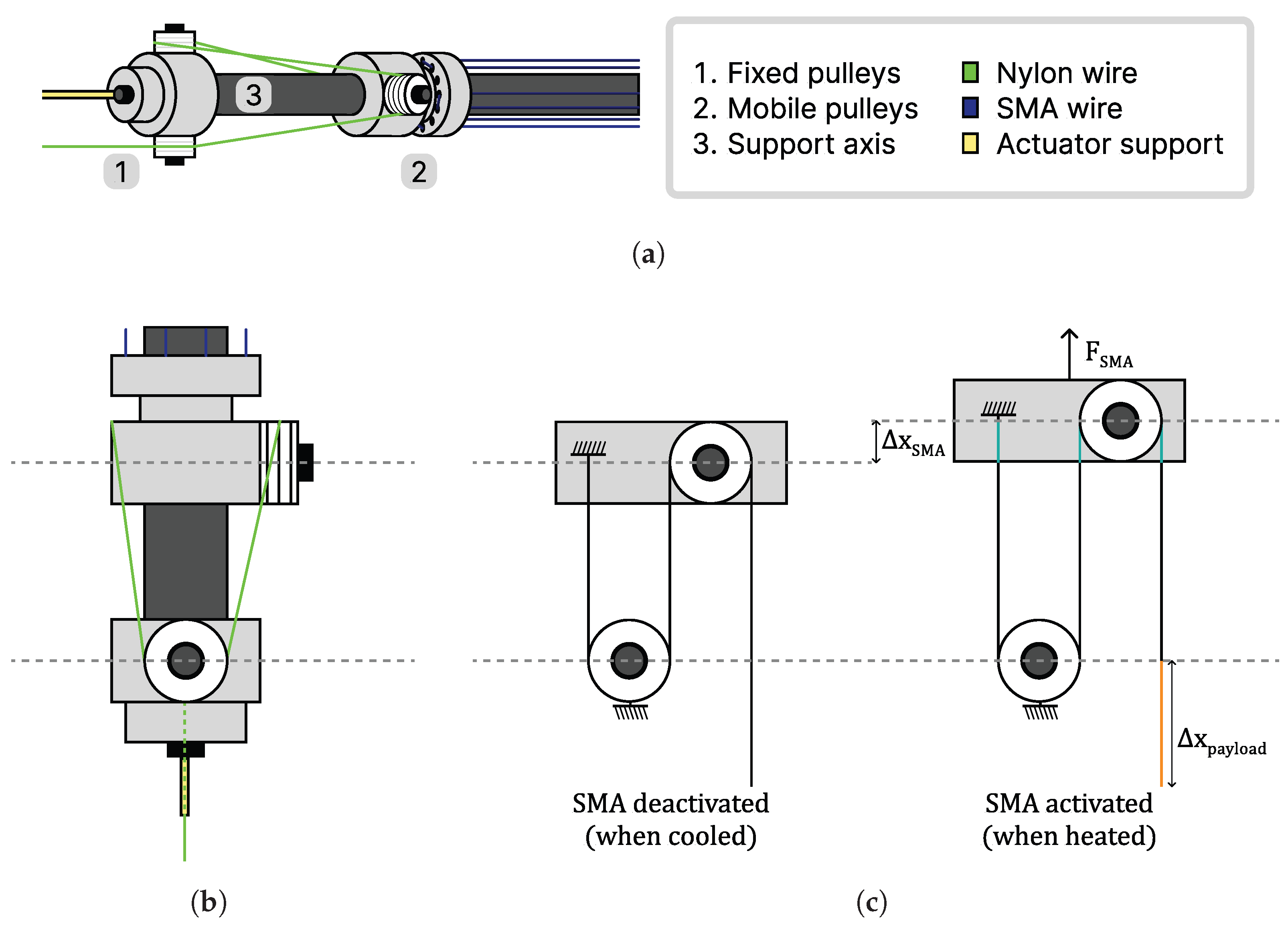
In terms of SMA-based actuator performance, the percentage of displacement with respect to the total length is a critical parameter in some applications. The proposed application for the developed actuator is a wearable exosekeleton for rehabilitation therapies, where the size and weight constraints are imposed by the nature of the task. Such challenging length restrictions were addressed in this study by designing a built-in hoist system that multiplied the SMA wire contraction and increased the total movement. The design also included parallel wire actuation to increase the load capacity. In contrast with the approaches proposed in the literature, using this mechanism did not add complexity to the system because the behavior of the hoist was linear with respect to the position. Moreover, the production of the actuator did not require sophisticated sewing methods or expensive hydraulic devices. When using the actuator in exoskeletons, the relationship between load capacity and actuator weight increased user comfort and was more portable. In addition, to comply with movement restrictions during rehabilitation therapy, a novel controller was developed. The controller was specifically designed for SMA-based artificial muscles and used a combination of classic approaches and mathematical characterizations of the reference and error for precise position control without requiring a model. By defining a few adjustable parameters based on the actuator’s properties, the controller produced precise and noise-free results that were both accurate and repeatable, making it well suited for exoskeleton applications.
This paper is divided into five sections: In
Section 2, the study’s methodology is detailed; this includes an analysis of the hoist system, the multiwire configuration, the design configuration parameters, and the components of the test bench.
Section 3 details the proposed nonactuable system state controller for the position control of SMA wires;
Section 4 provides the results of the actuator and a comparison of the results of different tests in which the frequency and task load were varied, as well as a discussion of these results. Finally,
Section 5 presents conclusions concerning the achieved results, as well as directions for future studies and related lines of research.
3. Control Strategy
Working with SMAs presents some challenges, with the main issue being their highly nonlinear behavior. Actuators based on these materials experience intensified hysteresis, sensitivity to environmental conditions, and inherent material fatigue. These properties make nonlinear algorithms an appropriate option for SMA actuators, as they are also more difficult to implement and calibrate than linear controllers. In addition, in the proposed design that was detailed in
Section 2.2, the actuator used parallel actuation, so we could not confirm that the wires worked at the exact same tension—the values could be slightly different. The result was a sum of different nonlinear models controlled by a single controller, which could lead to the breakage of the wire if one of them supported more force than the others.
According to the material restrictions and properties, the most classical and easy-to-implement controller is based on the PID method. Assuming that the power electronics send a PWM current to the actuator, the controller calculates the duty cycle of the signal according to
where
is the PWM duty cycle,
,
, and
are the proportional, integral, and derivative gain, respectively, and
is the error between the reference and the output. The PID gains were adjusted experimentally by observing the SMA’s response.
However, the material temperature cannot be directly controlled, though this is the variable responsible for the transformation and shape memory effect. Heating an SMA by using the Joule effect and controlling the intensity that passes through the wire with a PID does not provide acceptable performance under certain task restrictions, especially during the cooling phase. In this study, a new strategy was developed for systems that present states that cannot be controlled, which we call a nonactuable system state (NASS) controller. The main control loop, as shown in
Figure 7, is composed of two additional components that provide a solution to the instabilities related to the cooling of the wire.
The first problem with the actuator configuration is related to SMAs’ characteristic cooling curve. Accordingly, at the start of the cooling phase, the position rapidly recovers, and then the process slows in the form of a negative exponential function. Due to the absence of the antagonist configuration, if the load is lighter than the recovery force or if the frequency is too high, the wire does not return to its original form. Hence, at the end of the cooling state, a substantial error that cannot be removed is accumulated and increases the controller signal. At the start of a new cycle, this error increases the control action, leading to instabilities and a delay. This problem is solved by implementing an anti-windup block in the controller, which actuates as error preprocessing when the position overshoots the reference. This is mathematically modeled by using a sigmoid function to preserve continuous and smooth signal behavior.
where
is the original error signal,
is the hardness of the sigmoid function, and
is the threshold error value; the latter two were both adjusted experimentally.
If the SMA overheats, the control signal should be null in order to cool it, so the error during this phase is weighted to nearly zero. By not accumulating an error signal, the response in the next step is faster and reaches that of the reference without producing future oscillations. Moreover, the PID receives a reset signal at each cycle to remove the integral accumulated error. By combining Equations (
3) and (
4), the control signal
is obtained:
The performance obtained with this modification is acceptable, but two notable problems that substantially decrease the final results remain. The first is related to the instabilities produced when the position overshoots the reference, and the second one is related to certain positions that might be susceptible to overshooting. Both of these problems are solved with the reference gradient adaptive signal smoother (RGASS), a new block that we designed to improve SMA performance, and it is composed of an overshoot stabilizer and a critical region variable gain. The final control signal is defined by the following general equation:
where
is defined in Equation (
5),
is the overshoot stabilizer, and
is the critical region variable gain.
As defined by thermodynamics, for the temperature of a material to decrease, the heat supplied must be less than the heat dissipated. In non-agonist–antagonist designs, when the position overpasses the reference because the material is overheated, the only solution is to turn off the controller’s action. Due to SMA heat dissipation delays, error accumulates, and the following PID response is intensified; the reference is overshot again and an on–off controller that produces fluctuations and instability in the position is created. To solve this issue, a new block called an overshoot stabilizer was implemented. It adds an offset to the controller when the error is negative, thus keeping the control signal above zero. This minimal value avoids the oscillations produced in the heating phase and improves the general performance, thus smoothing the nonactuable state correction. It depends on the reference gradient and the error and is mathematically modeled as follows:
where
and
are temperature constants that are adjusted depending on the actuator’s thermodynamics and the selected reference, respectively;
n is the threshold error value.
The critical region variable gain is defined as an additional gain added to the control signal to maintain the position at stable values depending on the reference gradient, which contains information about the system. The sign indicates a heating or cooling state, and the magnitude indicates the velocity of the transformation. This gain produces a weighting of the control signal to decrease its value when the region is susceptible to overshooting. First, the relationship between the current gradient and the total reference amplitude is obtained with Equation (
8) to establish the relative speed of the change. At a position in which this relationship is close to zero, the position belongs to a critical region. For example, when the gradient reaches zero and the cooling state is starting, the control signal generated by the PID is slightly reduced, and the movement is smoothed.
where
is the reference gradient, and
A is the total signal amplitude.
By using this value, we can calculate the variable gain that weights the previous control signal, which is mathematically obtained by using the following equation in sigmoid form to maintain continuous signals and smoother behavior:
where
is the reduction coefficient for the signal in the critical regions,
is the sigmoid hardness, and
is the gradient threshold, which can be experimentally adjusted according to the specific application.
The output of the controller is a signal saturated between 0 and 100, representing the duty cycle of the PWM signal. This value is computed by the power electronics, which generate the real signal and send it to the actuator, as shown in
Figure 7. The amplitude of the intensity depends on the electrical properties and configuration of the SMA wires. In this case, the amperage relies on the single-wire tolerance and the parallel configuration. With the resistance and longitude of each wire, the voltage can also be obtained.
When applied to the SMA actuator, the NASS controller has the robustness of a classical PID controller while being able to accordingly respond to the restrictions in the system that increase control complexity. The nonactuable state is a critical region during control because this state can easily lead to instabilities and oscillations in the position of the actuator. For testing, various experiments were conducted, and the loads and work frequencies were varied. Overall, the controller ensured steady and continuous movement during the heating stage during various working cycles. The obtained actuator response was compared with that of the PID controller; an analysis is presented in
Section 4 for different loads and working frequencies.
4. Results
For the specific design parametrization of the developed actuator,
SMA wires with a diameter of
, a length of
m, and an activation temperature of 90 °C were selected. As the wires were not perfectly tensioned and the payload was not immediately displaced, we assumed
as the percentage of wire contraction. The designed hoist system exhibited an MA of
; so, the maximum payload displacement was multiplied by three. The total mass of the actuator was 20 g. According to the manufacturer’s specifications [
33], each wire was able to lift 2.25 kg. After considering parallel actuation and the hoist system, the final load capacity was
kg. The actuator could theoretically lift 300 times its own weight. However, the design and calculations did not consider the effect of friction; for this reason, the maximum payload tested was 2.5 kg to prevent wire breakage. The actuator was found to be able to lift 100 times its own weight, resulting in an efficiency of 41.17%.
The controller parameters, which are detailed in
Table 1, were adjusted by observing the actuator’s response to the reference signal. The position was measured in sensor units, with a conversion rate of
μm. The reference, position, and error are expressed as
, but, for clarity, they are shown in centimeters. Therefore, the PID gains are expressed as
.
4.1. Experimental Results
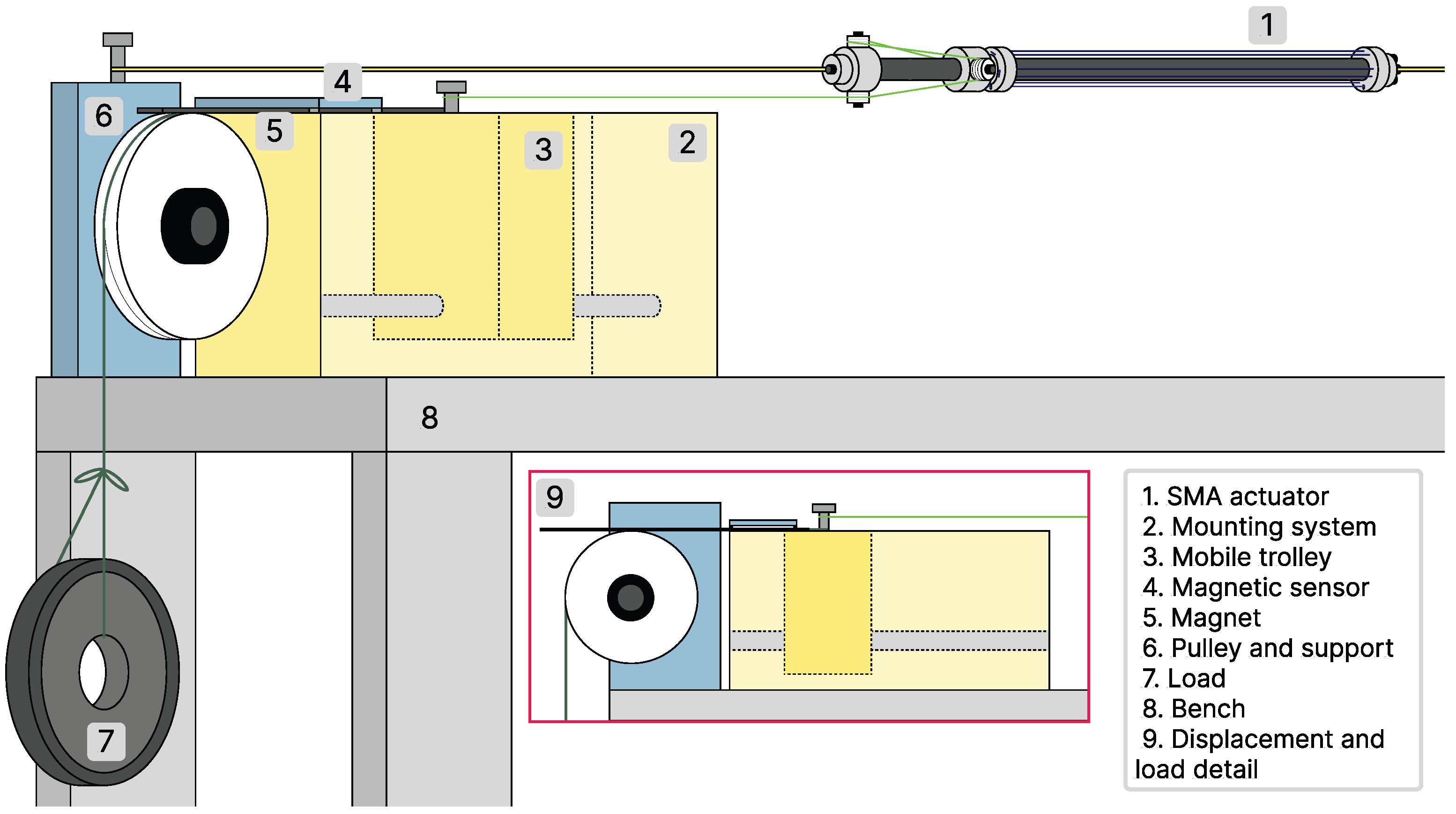
To study the actuator’s responses to different working conditions, various tests were executed. The position reference was generated with a sinusoidal signal, the amplitude of which was within the range of maximum displacement. This signal provided continuous, smooth movement, which is useful for many SMA-based actuator applications. The actuator’s response was mainly affected by both its attached payload and the reference signal frequency. These two experimental parameters are important considerations when using smart actuators in real-life applications because they directly influence the final performance. For this reason, a range of common working settings were tested by modifying the load in 0.5 kg increments and the frequency in 0.1 rad/s increments. Each test was conducted for 600 s under the same environmental conditions: at 25 °C and isolated from external airflow convection. To allow the SMA to dissipate heat and return to its original form between tests, external tension was applied, and the wire was allowed sufficient time to completely cool.
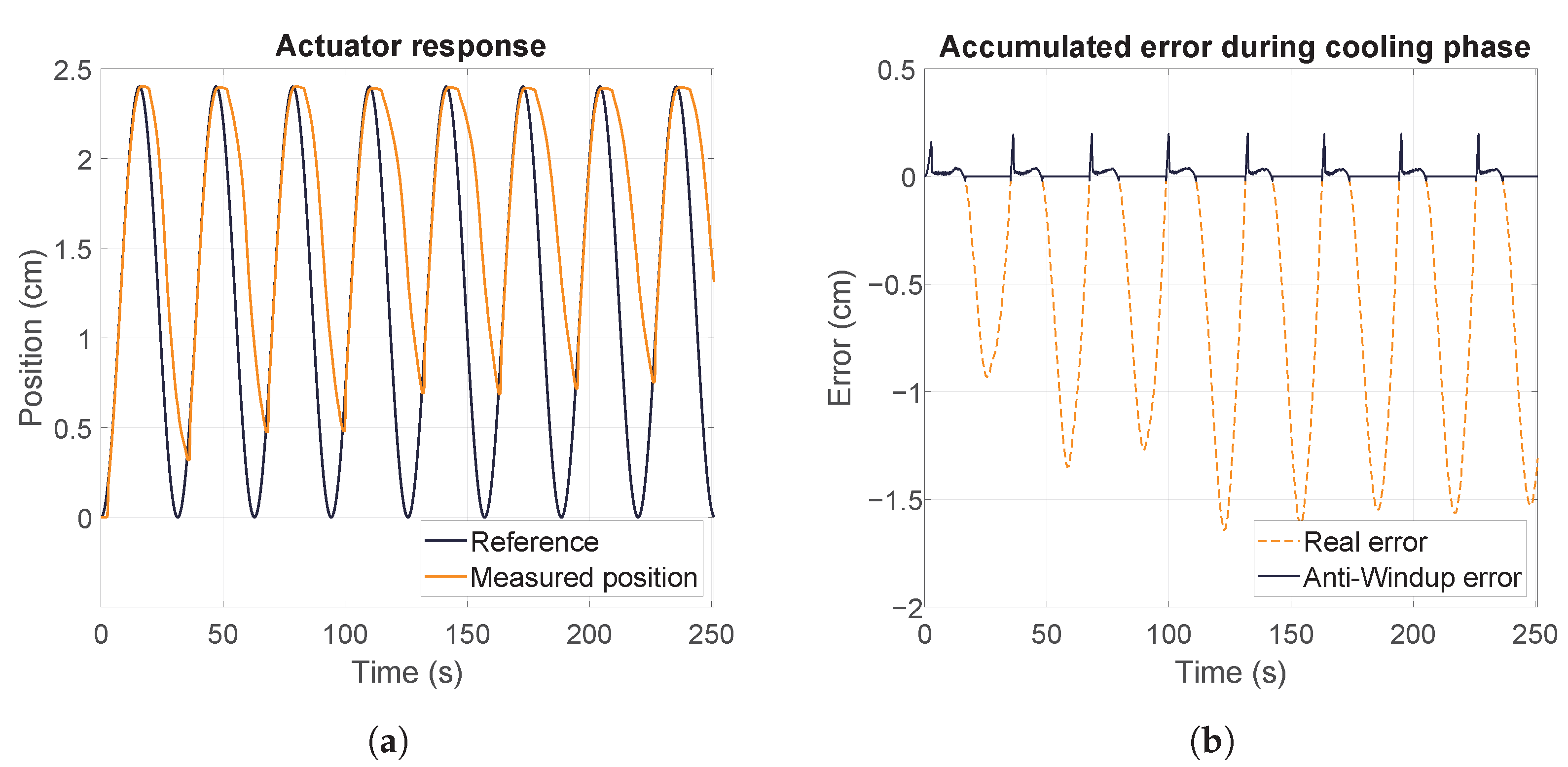
Figure 8 shows the actuator’s response to one test as an example of the general behavior that was obtained. Overall, the results demonstrated that the actuator performed correctly under various conditions, reaching the maximum and following the reference with a smooth trajectory, as shown in
Figure 8a. However, we found that a delay occurred in the maximum of the signal at the start of the cooling phase. This delay was produced because of the number of heated SMA wires and the small distance between them, which caused the surrounding air temperature to increase, which hampered the cooling of the wire. We also observed that the recovery of the wires decreased with increasing cycles. This occurred because of the retained heat, which produced an increase in the wire temperature in each cycle. As a result, two states could be distinguished in each test based on recovery: the transitional and stationary states.
Despite the challenges presented by the cooling state, the actuator achieved the maximum displacement in each cycle. During the cooling phase, the real error was large because the wire could not be forced to cool down, as shown in
Figure 8b. The anti-windup block from the NASS controller eliminated the accumulated error, allowing the response at the beginning of each cycle to remain within the stability limits. As a result, the SMA reached the reference with an underdamped response, and the heating delays that negatively impacted the actuator’s response were substantially reduced.
4.1.1. Effects of Frequency and Load
The use of SMAs as actuators is associated with certain limitations, such as the requirement for a specific cooling time and forcing a return to their initial state. The frequency at which an SMA transforms between its two states considerably impacts the process. Operating at higher frequencies results in faster actuation, but can lead to lower displacement due to the material not having enough time to return to its original form. Conversely, operating at lower frequencies results in slower actuation, but can also result in higher displacement. Notably, the selection of the working frequency for SMAs may not be optimal for traditional engineering purposes, but in fields such as medicine, different standards apply, and SMAs can still meet the requirements in these fields.
The response of SMA-based actuators is highly dependent on the frequency of the reference signal. If the actuator’s configuration is not agonist–antagonist, as in the current study, its response is even more susceptible to variations in frequency. As depicted in
Figure 9a, when the cooling time is sufficient for the material to return to its original shape, the observed behavior is predictable and consistent with the theoretical recovery patterns. However, when the frequency is increased, as demonstrated in
Figure 9b, the displacement produced in each cycle decreases, as the SMA is unable to fully return to its original form.
As a result of the increased frequency, the recovery is not uniform, and each cycle exhibits oscillation in the minimum position reached, making the behavior more unpredictable and difficult to approximate and model. Furthermore,
Figure 9c shows that the delay produced at the maximum displacement can be disregarded for low frequencies, as it represents a relatively insignificant time in comparison with the cycle period. However, when the frequency increases, the delay negatively impacts the recovery of the SMA, as this delay is notably high with respect to the overall cooling phase, as shown in
Figure 9d.
Load can also affect the recovery of SMAs. In general, the recovery is influenced by the amount of stress or strain that is applied. The attached payload can impact the energy consumption because the deformation requires energy, which depends on the size and properties of this payload. The temperature is also related to the energy consumption, so heavier loads require more power, and the temperature reached by the wire is higher.
Figure 10 compares the thermal and strain effects produced by different payloads for a given frequency. Studying the position in
Figure 10 shows that lighter payloads initiate the cooling process earlier, whereas higher payloads result in increased heating of the wires and slower heat dissipation. However, in terms of recovery, higher payloads tend to better return to their original form because of the higher steepness of the cooling curve. This occurs because the the wire is more rapidly quenched when the temperature difference is larger, and the difference between the environment and the wires in these tests was larger.
4.1.2. Comparison of NASS and PID
The proposed controller produced a proper response for a multiwire actuator with a high displacement, but we needed to compare the obtained results with those produced by other controllers proposed in the literature to validate the findings. The primary control strategy found in the literature for controlling the position of SMA wires was the use of a PID controller, which presents limitations in nonlinear systems, as discussed in
Section 3. The same tests described in
Section 4.1 were conducted again, but while using a PID block with the established proportional, integral, and derivate gain listed in
Table 1.
Neurorehabilitation focuses on the establishment of simple repetitive exercises that allow a patient to recover the ability to perform daily tasks with autonomy. For this reason, robotic rehabilitation devices must enable a patient to perform the movements prescribed by a medical specialist while reinforcing the targeted muscle groups [
38]. Consequently, an evaluation of system trajectory, in addition to the examination of the parameters that enhanced the actuator’s lifespan, was of paramount importance in this comparison.
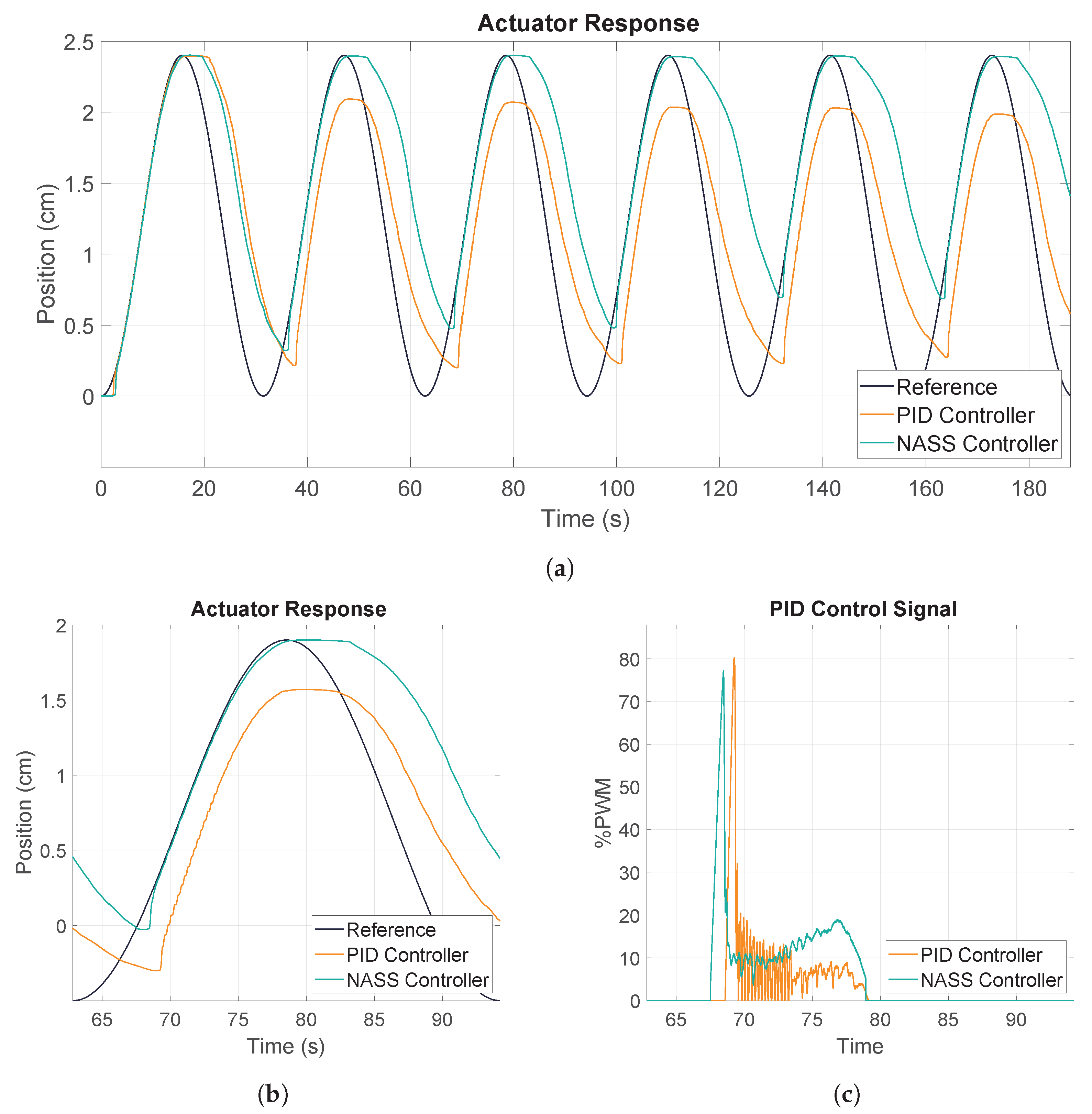
The initial tests were conducted at low frequencies to study the system’s response under optimal conditions. The PID control performed satisfactorily when the wire was able to return to its original form due to the sufficient length of the signal period. However, when the frequency increased, the PID controller presented various limitations. A notable difference observed in the results was the maximum value reached by the two controllers, as illustrated in
Figure 11a. In the first cycle, both controllers achieved the maximum value and experienced thermal delay, but the PID controller lacked the anti-windup block, resulting in a delay in the control action during the subsequent cycle. This led to a higher position integral error and a failure to reach the maximum position. In contrast, the recovery of the wire was more favorable with the PID, as the wires initiated cooling at a lower position. This behavior was consistent over multiple cycles, but the maximum displacement decreased due to the transition to the stationary recovery state and the error accumulated during the cooling phase.
A closer examination of the signal while focusing on a single cycle, as depicted in
Figure 11b, revealed another notable difference in the generated position. The PID signal exhibited a stepped behavior, which was typical of on–off control, whereas the NASS controller produced a smooth movement that closely followed the reference. This was further supported by the control signals shown in
Figure 11c. The NASS control signal remained slightly higher and smoother, which increased power consumption, but was beneficial for the actuator’s response and lifespan. The PID signal extensively oscillated between zero and higher values, introducing noise into the system and producing an oscillatory behavior.
Although the controller presented in this paper demonstrated satisfactory performance, it is not without limitations. One major limitation is that the parameters were initially set based on prior knowledge of the system and were adjusted through observation of the actuator’s response during testing. Additionally, these parameters were subject to variation based on the environmental conditions—particularly the temperature. Further studies are needed to investigate the controller’s response to alternative reference signals, such as step inputs. Another important consideration is the impact of friction and heat dissipation on the overall performance of the controller; thus, future developments should focus on addressing these issues to enhance the controller’s efficiency.
4.1.3. Forced Cooling Comparison
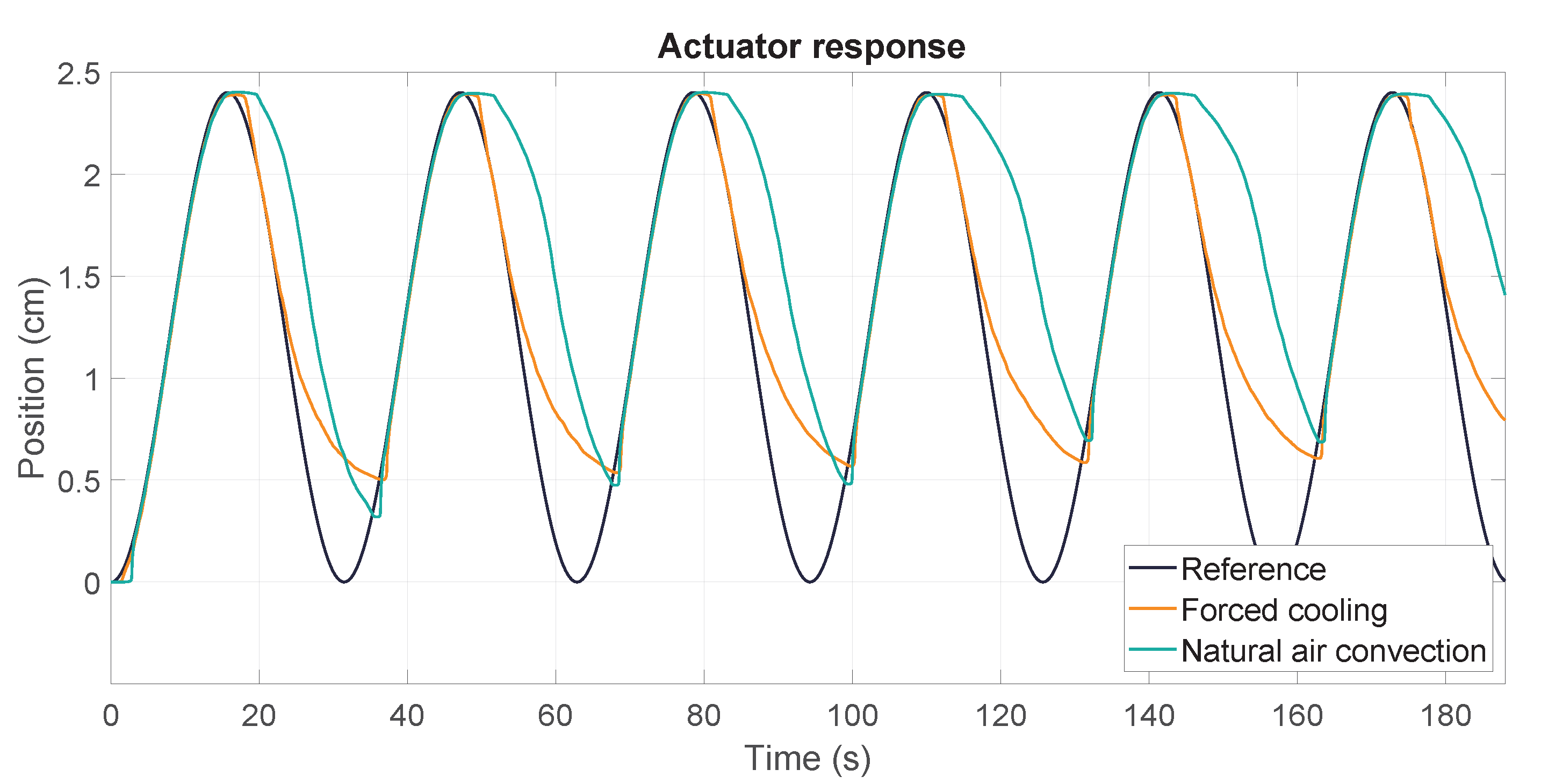
To enhance the performance of the actuator and examine the effect of environmental temperature on recovery, an additional test was conducted while using a power supply fan to cool the SMA. This fan was positioned below the actuator and maintained a constant air flow during both the heating and cooling cycles to force the ventilation of the wires. The results are displayed in
Figure 12, in which the actuator’s response is compared with that achieved with natural and forced air convection. The results revealed that the environment negatively impacted the performance of the SMA wires by absorbing heat from them. This resulted in a delayed response and a less efficient cooling curve during the initial stages of the cooling phase. However, when the environment was refrigerated by using a fan, the SMA wires were able to start the cooling phase without any interference from the environment.
In both cases, the recovery rate was affected because, although the wires were externally cooled, the system was a heat accumulator. This implied that during the cycles, the internal temperature of the wires increased, and the recovery rate decreased until it stabilized at a certain value. The natural air convection cooling method produced improved recovery in the initial cycles of the test; however, forced air convection maintained more consistent results and ultimately resulted in better overall recovery. Furthermore, the forced cooling produced a typical SMA cooling curve, thus demonstrating the effectiveness of the fan in improving the performance of the actuator.
4.2. Discussion
In general, the actuator demonstrated the ability to reach its maximum capacity and exhibited satisfactory behavior in the majority of the tests that were conducted. However, when the frequency was set to 0.4 rad/s and a payload of 1.00 kg was attached, the wire was unable to return to its original form within the allotted time and mass, resulting in a discarded test outcome. This value was then established as the upper limit of the actuator’s response.
4.2.1. Recovery Analysis
As previously demonstrated in the results in
Section 4.1, one of the primary challenges associated with the use of SMA-based actuators is the recovery to the actuator’s initial shape. This issue is closely tied to the cooling of the wires and directly impacts the operating frequency of the actuator. The recovery process is influenced by a variety of factors, including the magnitude and nature of the applied payload, the temperature of the material, the frequency of activation, the composition of the SMA, and the heat treatment of the material. With this type of actuator, increasing the frequency results in a decrease in the total displacement produced during each cycle, as the actuator may not have sufficient time to return its original shape. To further understand this limitation and investigate potential applications and use cases,
Table 2 presents the mean recovered value in comparison with the initial wire length, as calculated based on the minimum position reached in each cycle during the 600-second tests.
The elevated standard deviation observed in the previous results can be attributed to the transitional recovery phase of the SMA wires; due to their own internal heating, the recovery decreased with increasing cycles until the establishment of a stationary recovery phase. This value was the nominal displacement that the wires produced; even though the establishment time varied according to the frequency, it was typically observed within the first three cycles. From the fourth cycle onward, the SMA wires could be assumed to be operating in their stationary recovery phase, and the mean recovery value for this phase could be calculated. These values are presented in
Table 3, which demonstrates that, overall, the recovered percentage decreased by approximately 2–4% and the standard deviation improved.
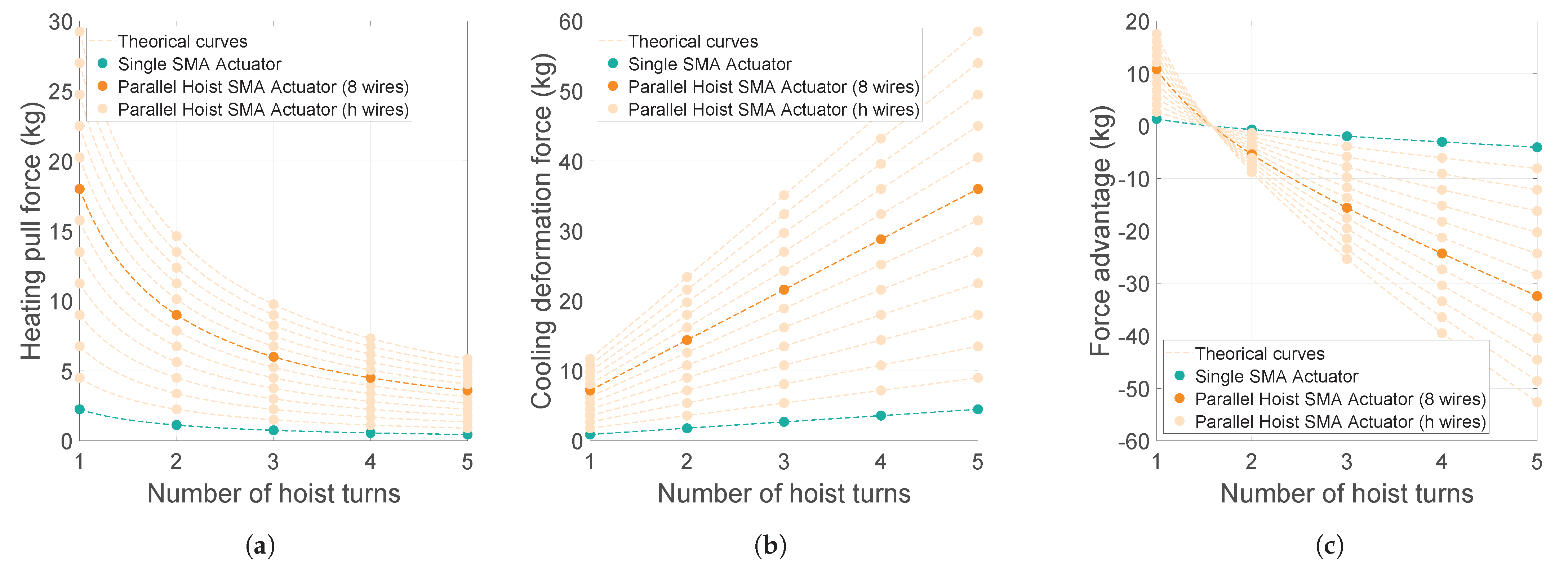
Overall, the recovery of an SMA is influenced by two main factors: frequency and load. In the proposed design, because of the hoist system, the maximum heating pull force was weaker than the necessary cooling force, as shown in
Figure 4. When the frequency was low enough, increasing the attached load improved the recovery. The thermal delay in this scenario was the shortest, and the cooling curve increased faster for high loads. By increasing the frequency to 0.1 rad/s, the effect of the load was less pronounced than in the previous case, but it was still observed. When the frequency was increased to 0.4 rad/s, the wires did not have enough time to cool, and the cooling process could not occur normally. For this case, lighter loads exhibited better recovery because they required less temperature to reach the maximum value, resulting in a shorter thermal delay. The highest frequency considered in this study was 0.4 rad/s because, with this value, the percent of length recovered was overly small, and the actuator’s response was unacceptable. With this frequency, the produced delay was substantial and negatively impacted the results, producing nonuniform recovery data and an unpredictable SMA response in each cycle. In general, the load is determinant in the percentage of recovery within a given range of frequencies, but for high values, the results become irregular regardless of the load.
4.2.2. Single-Actuator Displacement Comparison
After calculating the nominal displacement produced for this design, we could compare the obtained results with those of a single SMA-based actuator. The hoist system detailed in
Section 2.2 provided an increase in the maximum displacement; for this configuration, where
, the maximum displacement was, therefore, multiplied by three. In
Figure 13, the nominal displacement accomplished for each payload and frequency is presented and compared with the theoretical maximum displacement of a single SMA-based actuator without the high-displacement hoist system approach.
In this comparison, we did not consider the characteristic transitional phase for SMA wires for a single actuator because its maximum theoretical displacement value was used. Therefore, the absence of data on the decrease in the total displacement produced over the cycles due to the heating of the wires produced an advantage for the single actuator. However, the actuator with the hoist system developed here accomplished an increased displacement for a common range of working frequencies. Comparing the results with those of the nominal displacement of a single actuator for the same range of frequencies would lead to a larger difference in the range of movement; yet, at this stage, we could validate the hoist system as a robust high-displacement device for improving SMA-based actuators. Reducing the total actuator size enables increased implementation of this technology in wearable robotics and exosuits in different fields of knowledge, such as bioengineering and rehabilitation.
Low frequencies, as shown in
Figure 13, were more responsive to the effect of the load on wire recovery; as the cycle period decreased, SMA recovery became irregular, and the payload no longer had such a strong effect on the results. For the test that was conducted at a frequency of 0.4 rad/s, the cooling time was insufficient for the wire to return to its original form. Therefore, the achieved displacement was unsuitable because it was under the maximum displacement of the single actuator. However, for a better comparison at high working frequencies, an in-depth study of the response of a single SMA-based actuator must be performed. Overall, the working frequency may be improved by eliminating the delay at the beginning of the cooling phase and by studying and modeling the effects of friction and the thermal responses of materials.
