Article

Performance Evaluation of a High-Torque Permanent Magnet Brake at Operating Temperature Based on Magneto-Thermal Coupling Method

1
College of Mechanical and Electrical Engineering, Wenzhou University, Wenzhou 325035, China
2
Pingyang Institute of Intelligent Manufacturing, Wenzhou University, Wenzhou 325400, China
3
College of Business, Shaoxing University, Shaoxing 312000, China
*
Author to whom correspondence should be addressed.
Actuators 2023, 12(4), 149; https://doi.org/10.3390/act12040149
Submission received: 2 March 2023 / Revised: 27 March 2023 / Accepted: 28 March 2023 / Published: 30 March 2023
(This article belongs to the Section Control Systems)

Abstract

:
As the key component of a servo motor, the torque and temperature rise of the brake at the operating temperature affect the production quality of injection molding machines and other equipment. To achieve application of the brake and evaluate its performance at a high operating temperature, a high-torque permanent magnet brake with an axial disc structure is proposed. The permanent magnet consists of six small magnets instead of the traditional monolithic ring magnet. The key parameters of the coil are designed, and the magneto-thermal coupling method is established. The magneto-thermal coupling method considers the effect of temperature on material properties and feeds the temperature back to the electromagnetic field to correct the resistance, permeability, remanence and other coefficients. It then updates the heat source of the temperature field. The temperature rise is calculated iteratively between the electromagnetic field and the temperature field. The simulation results of the one-way method and the magneto-thermal coupling method are obtained and compared with the experimental results. The evaluation errors of the magneto-thermal coupling method for temperature and braking torque are 1.9% and 4.7% respectively, which are lower than the errors of the one-way method.

1. Introduction

Brake is an important component of the servo motor control system in machine tools, injection molding machines and other industrial fields. As an indispensable part of many types of mechanical equipment, its quality, stability, safety and service life will directly affect the control quality of the whole system [1,2]. For example, brake failure in an injection molding machine will not only affect the accurate control of the motor [3] but will also block and burn the motor and may even cause major safety accidents [4,5]. Compared with the traditional non-excited brake, the permanent magnet brake has the advantages of low energy consumption, high braking torque, short response time, easy control and a long service life [6], which is a research hotspot in the field of electromagnetic mechanism.
In recent years, the principle and method of electromagnetic mechanism have been studied: Yong Li established mathematical models and simulations to discuss the stroke force characteristics and generation mechanism of electromagnetic separation mechanism [7]. Siwen Li studied the temperature rise of the electromagnet by adjusting the energized winding time and analyzing the cold and hot resistance and waveform of the winding [8]. M. R. Dilshad proposed a stator temperature estimation method based on the energy model [9]. Jinhua Tang focused on a dual-rotor permanent magnet braking device to improve the thermal attenuation performance of a friction braking device [10]. Li Lei established the magneto-thermal coupling method of an eddy current brake under a strong impact load [11]. Yumeng Fan obtained the influence law of electromagnetic parameters on the force characteristics of an eddy current brake through a finite element numerical calculation [12]. Jiahao Li established a subdomain analysis model of an eddy current brake and further calculated and compared the resistance characteristics of radial, axial and Halbach arrays under impact loads [13].
In summary, most scholars have mainly focused on researching electromagnetic mechanisms such as generators, motors, relays and solenoid valves, but few research achievements have been made on the application, innovation and theoretical model of high-performance permanent magnet brakes under high-temperature conditions [14,15,16].
In this paper, a high-torque permanent magnet brake for an injection molding machine is proposed. To evaluate the performance of the high-torque permanent magnet brake, the influence of parameters on the permanent magnet brake components at a high operating temperature is discussed based on the coupling model, which combines the electromagnetic field with the temperature field. In the process of a magneto-thermal coupling simulation, the loss in the electromagnetic field is calculated first, and the loss result is then imported into the temperature field as the heat source. As some material properties such as resistivity and permeability are related to temperature, the electromagnetic loss of the brake will change with the change in temperature. Therefore, it is necessary to recalculate the temperature rise caused by electromagnetic losses and feed the results back to the material properties of the electromagnetic field. The continuous iteration coupling cycle is then carried out to obtain the actual temperature distribution and temperature rise of the brake. The results of the static torque, temperature distribution and the temperature rise of the high-torque permanent magnet brake at operating temperature are evaluated based on both the one-way method and the magneto-thermal coupling method and are verified by an experimental study.

2. Design for High Torque Permanent Magnet Brake

2.1. Structure Design

The brake is mainly used for the servo motor of an injection molding machine. Thus, the following factors need to be considered: (1) a high braking torque; (2) a high operating temperature of 70–90 °C; (3) a limited working space. Compared with a traditional non-exciting brake, a permanent magnet brake uses a permanent magnet as power source, while a traditional non-exciting brake uses a spring as a power source. Under the same volume, a permanent magnet brake has a higher braking torque. At a working temperature of 70–90 °C, the elastic modulus of the spring will be reduced, thus reducing the life and stability of the brake, while the permanent magnet can reach a high working temperature of 150 °C. In order to obtain a higher torque, non-exciting brakes (Figure 1a) need to increase the number of springs, while permanent magnet brakes can be achieved by modifying the internal structure.
The structure of the high-torque permanent magnet brake is provided in Figure 1b, which is mainly divided into the stator and the rotor. The stator is composed of a permanent magnet, outer yoke iron, inner yoke iron and coil, and the permanent magnet consists of six small magnets instead of the traditional monolithic circular magnet. The rotor is composed of the disc armature, plate spring and outer flange. The outer yoke iron, inner yoke iron and armature are made of a magnetic material, and the coil holder is made of a nonmagnetic material [17]. The coil is placed in the axial direction between the permanent magnet and the disk armature to ensure that the rotor can be separated smoothly in the axial direction when energized. Figure 1c shows the exploded view of the permanent magnet brake.
The working principle of the high torque permanent magnet brake is as follows. As shown in Figure 2, when the coil is unenergized, two basic magnetic loops are formed under the action of the permanent magnet. One loop, I1, passes through the air gap, δ1, along the long end of the outer yoke iron from the N pole of the permanent magnet. It enters the armature, passes through the air gap δ1 again, passes through the inner yoke iron back to the S pole of the permanent magnet, and generates an axial suction force on the armature. The magnetic force of the permanent magnet acting on the armature and the yoke iron is used to brake the rotor when unenergized. The magnetic circuit I2 returns from the N pole of the permanent magnet to the S pole of the permanent magnet through the air gap δ2 along the outer yoke.
When the coil winding is energized, the magnetic loop generated by the coil, I3, passes through the inner yoke, air gap δ1, the armature, air gap δ2, the outer yoke iron, and air gap δ3 and returns to the inner yoke iron. Thus, the coil will produce an inverse magnetic field to counterbalance the magnetic field generated by the permanent magnet, resulting in the separation of the rotor and the stator by the plate spring.

2.2. Coil Design

According to the design requirements of coil winding in a limited space, some key parameters, such as the copper wire diameter, cross-section shape and resistivity, must be discussed to obtain a related expression of turns and resistance [18].
(1)
The coil number of turns
Two rows of copper wires are arranged in a staggered fashion. The single-layer turns, Nd, the layer number, Mc, and the average perimeter, Cr, of the coil can be calculated according to the section shape and coil diameter:
N d = L Φ
M c = H c Φ Φ × sin 60 ° + 1
C r = D c + d c 2 × π
where L is the width of the coil section, Hc is the height of the coil section, Φ is the copper wire diameter, Dc is the outer diameter and dc is the inner diameter of the coil.
Then the number of coil turns, N, is:
N = N d × M c
(2)
Coil resistance
After calculating the winding condition of the coil, the total length, C, of the copper wire can be calculated by Formula (5):
C = N × C r  
Then, the resistance of the coil, R, is:
R = 4 × C × ρ π × Φ 2  
where ρ is the resistivity of the copper wire.

3. Analysis Method

3.1. One-Way Method

In the one-way method, the loss of the electromagnetic field is taken as the load input of the temperature field, and the influence of the temperature rise on the electromagnetic properties of the materials is ignored. Figure 3 shows the one-way method flow chart: the temperature field is calculated by using the loss calculated by the electric magnetic field directly as the heat source without feedback, and the influence of temperature on material properties is ignored.

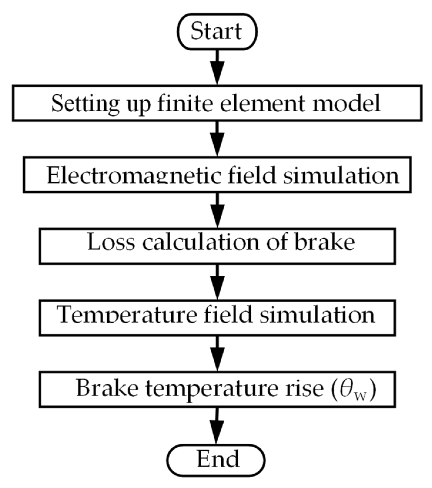
3.2. Magneto-Thermal Coupling Method

When the operating temperature varies greatly, the influence of temperature on material properties such as resistance and reluctance should be discussed in order to obtain an accurate model [19]. The magneto-thermal coupling method adds feedback to the base of the one-way method to realize an iterative analysis of the temperature rise and electromagnetic field performance of a permanent magnet brake [20]. The coupling flow chart of the brake is shown in the Figure 4. First, the initial material parameters are set, and the electromagnetic field simulation is carried out to solve the electromagnetic field loss. Then the step size is set, and the electromagnetic field loss is used as the heat source to introduce the temperature field simulation model to solve the temperature distribution of the permanent magnet brake. Thirdly the temperature obtained by calculation in a certain step is fed back to the material setting of the electromagnetic field. The material properties under changes in temperature are then updated, and the loss is recalculated until the end of the iteration. This is a cyclic iterative process. Finally, at the end of a loop, the time is reset to zero, and the process is repeated until the temperature difference between the two iterations is less than 0.01% [21].
First, the material performance temperature of each component is related; therefore, the temperature rise of the brake, θw, is calculated by Formula (7):
θ w = ρ θ 2 k t f L ( N I H c ) 2
where θw is the relative temperature, ρθ is the resistance coefficient of the coil conductor, kt is the heat dissipation coefficient, and f is the coil filling coefficient.
Second, there is a slight relationship between the permeability of the magnetic materials and the magnetic flux density; however, the change caused by the magnetic flux density can not be ignored under the change of a rise in temperature. In the range of 25~120 °C, combined with Formula (8), the relative permeability, μr, can be expressed as:
μ r = B r × 1 α × θ w   H cj × 1 β × θ w  
where Br is the remanent magnetism, Hcj is the coercivity, α is the temperature rise coefficient of remanence, and β is the temperature coefficient of coercivity.
As the temperature changes, the resistance value of the coil windings will also change. The resistance value, R′, of the coil winding after a temperature change can be calculated according to Formula (9):
R = R × 1 + ρ c × θ w
where ρc is the temperature rise coefficient of the coil.
According to Formula (10), the magnetic force of the formula plate electromagnet is calculated as follows:
F = B 2 S   2 μ 0
where B is the magnetic flux density and μ0 is the vacuum permeability.
The contact surface between the stator and rotor is annular, and the equivalent friction radius, Rμ, can be calculated by Formula (11):
R μ = 2 R 2 3 R 1 3 3 R 2 2 R 1 2
where, see Figure 5, R1 is the inner diameter of the contact surface and R2 is the outer diameter of the contact surface.
According to the working principle of a permanent magnet brake, the braking torque only comes from the friction between the stator and rotor; therefore, the braking torque can be calculated according to Formula (12):
T = μ f × F × R μ
where T is the braking torque and μf is the friction coefficient of the contact surface.
The accurate determination of the friction coefficient under temperature changes is very complicated, but the friction coefficient can be simplified to a constant value over a small range of temperature changes. In this paper, the friction coefficient at 120 °C was selected as the calculated value, which is 0.22, according to practical experience.

4. Magneto-Thermal Coupling Analysis

4.1. Finite Element Model

In this section, the finite element method is used to analyze the magnetic thermal coupling of the brake. By means of the ANSYS-Workbench software, the iterative coupling of a permanent magnet brake was realized through the co-simulation of an electromagnetic module and a transient thermal module.
(1) Construction of brake 3D model:
Table 1 shows the structural parameters of the permanent magnet brake.
(2) Define materials:
(a) Coil winding
The winding material is copper (copper), and its material characteristics are: a relative permeability of 0.999991, a thermal conductivity of 400 W/(m·C), a specific heat capacity of 385 J/(kg·C), and a density of 8933 kg/m3.
(b) Permanent magnet
An NdFeB permanent magnet is a type of permanent magnet with good comprehensive magnetic performance. In this paper, the permanent magnet material N35SH was selected. Its material properties are as follows: a remanence of 1.285 T, a coercivity of 1022570.51 A/m, a thermal conductivity of 7.6 W/(m·C), and a specific heat capacity of 460 J/(kg·C).
(c) Soft magnetic material
The material of the inner magnetic yoke, outer magnetic yoke and armature has a low coercivity, a narrow hysteresis loop and a low power consumption. Pure electric iron was chosen.
(3) Transient Thermal
(a) Temperature setting
In order to better simulate the real working environment of the brake, the initial temperature was set at 70 °C, and the ambient temperature was set at 80 °C, which is consistent with the subsequent experimental settings.
(b) Heat transfer
As the gap between the coil and the stator is filled by epoxy resin glue, the components are in contact with each other, and the heat transfer is therefore mainly conduction. The thermal conductivity between the coil and the epoxy resin adhesive was set to 8 W/m2∙°C, and the thermal conductivity between the epoxy resin adhesive and the other components was set to 10 W/m2∙°C.

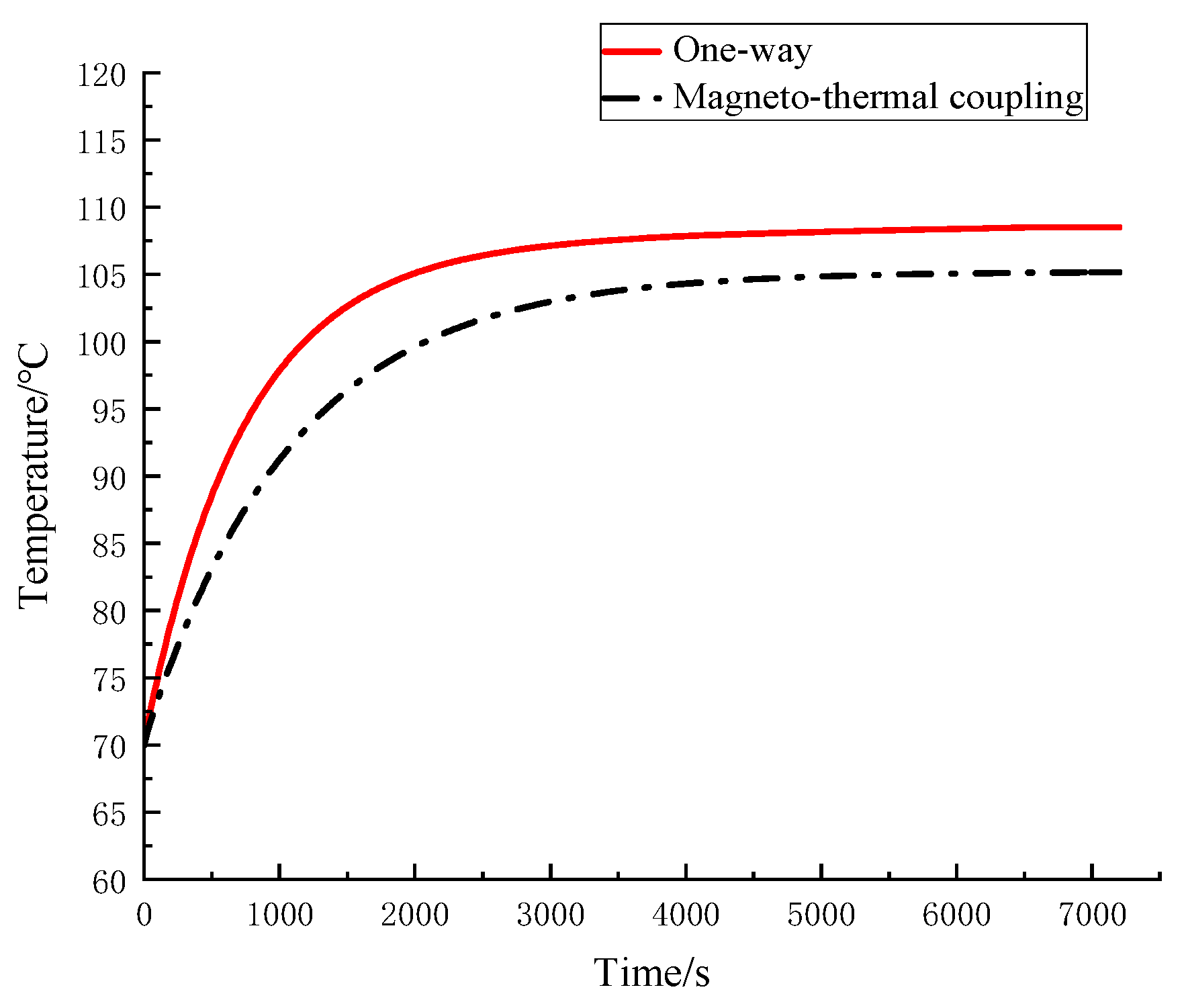
4.2. Temperature Rise Evaluation Based on Magneto-Thermal Coupling

Figure 6 shows the temperature distribution of the rear brake section at different power-on times: the legend ranges from 84 °C to 106 °C. In the first period (0–600 s), the temperature rises from 70 °C to 85 °C. It can be seen from the brake temperature–time curve that the temperature of the brake rises from fast to slow. At about 3600 s, the temperature rise range is less than 1%, and the temperature can be considered stabilized. In the axial direction, the temperature of the rotor is lower than that of the stator due to the inconsistent materials inside the brake, the poor heat dissipation conditions inside the stator and the high contact surface between the rotor and the air. In the radial direction, in addition to copper and iron losses, permanent magnets will also produce certain losses; therefore, the temperature distribution around the coil presents a downward stepped distribution of radiation.
Figure 7 shows the time–temperature curve of the permanent magnet brake in a transient analysis mode. The operating temperature is set to 70 °C, and the initial coil temperature is set to 70 °C. The initial simulation time is 0, the heat source loading time is the same as the simulation time, and the magneto-thermal simulation is completed through a 7200 s coupling iterative calculation. By comparing the two curves, it can be found that the steady-state temperature obtained by the magneto-thermal coupling method is relatively low because the feedback of the temperature field is added to the electromagnetic field. The temperature of one-way coil is constant, so the heat source power of the temperature field is basically unchanged. The temperature of the magneto-thermal coupling method coil is constantly rising, and the constant voltage source is used, leading to the constant decrease in the heat source power in the temperature field. Therefore, the temperature rise rate of the one-way method is higher than that of the magnetic thermal coupling method.

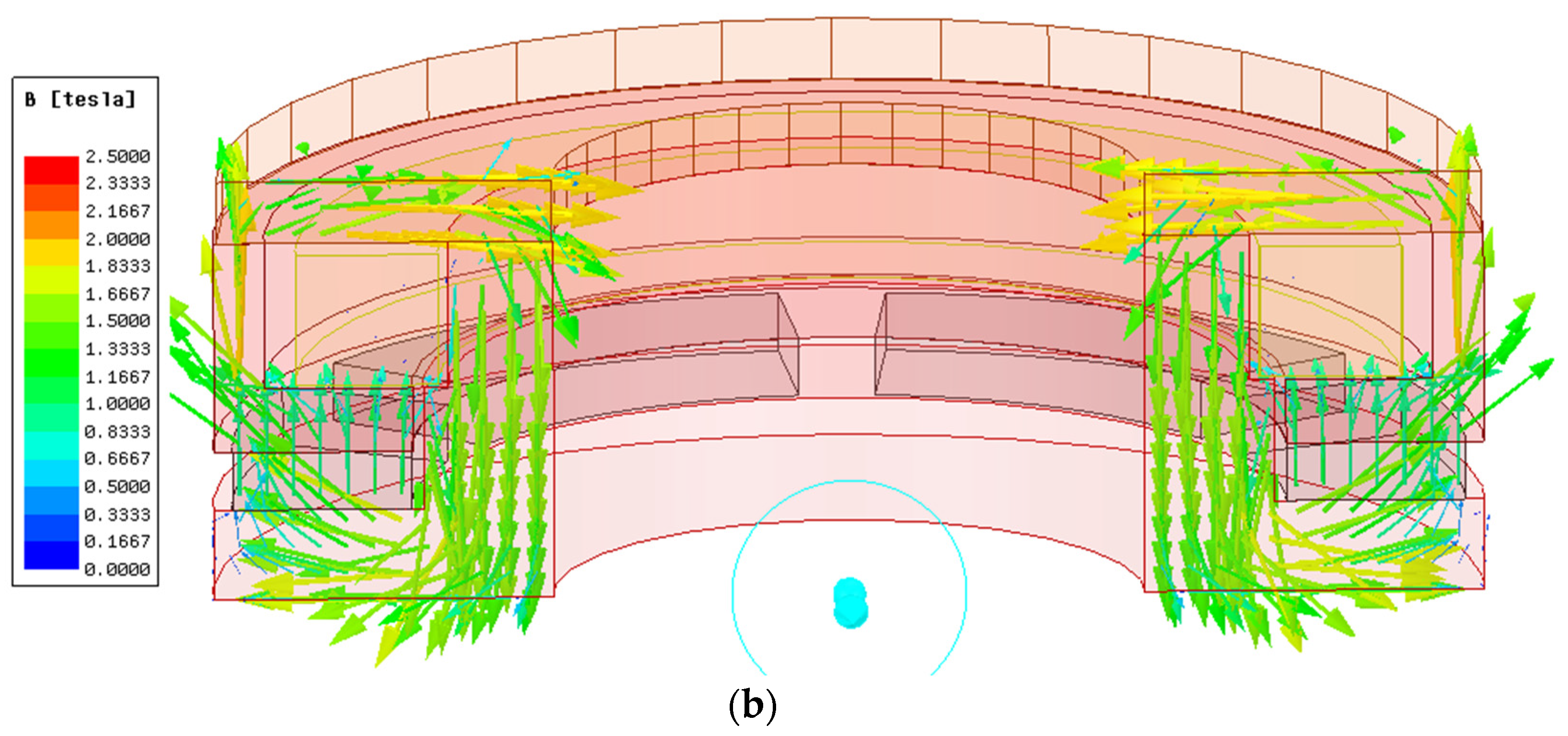
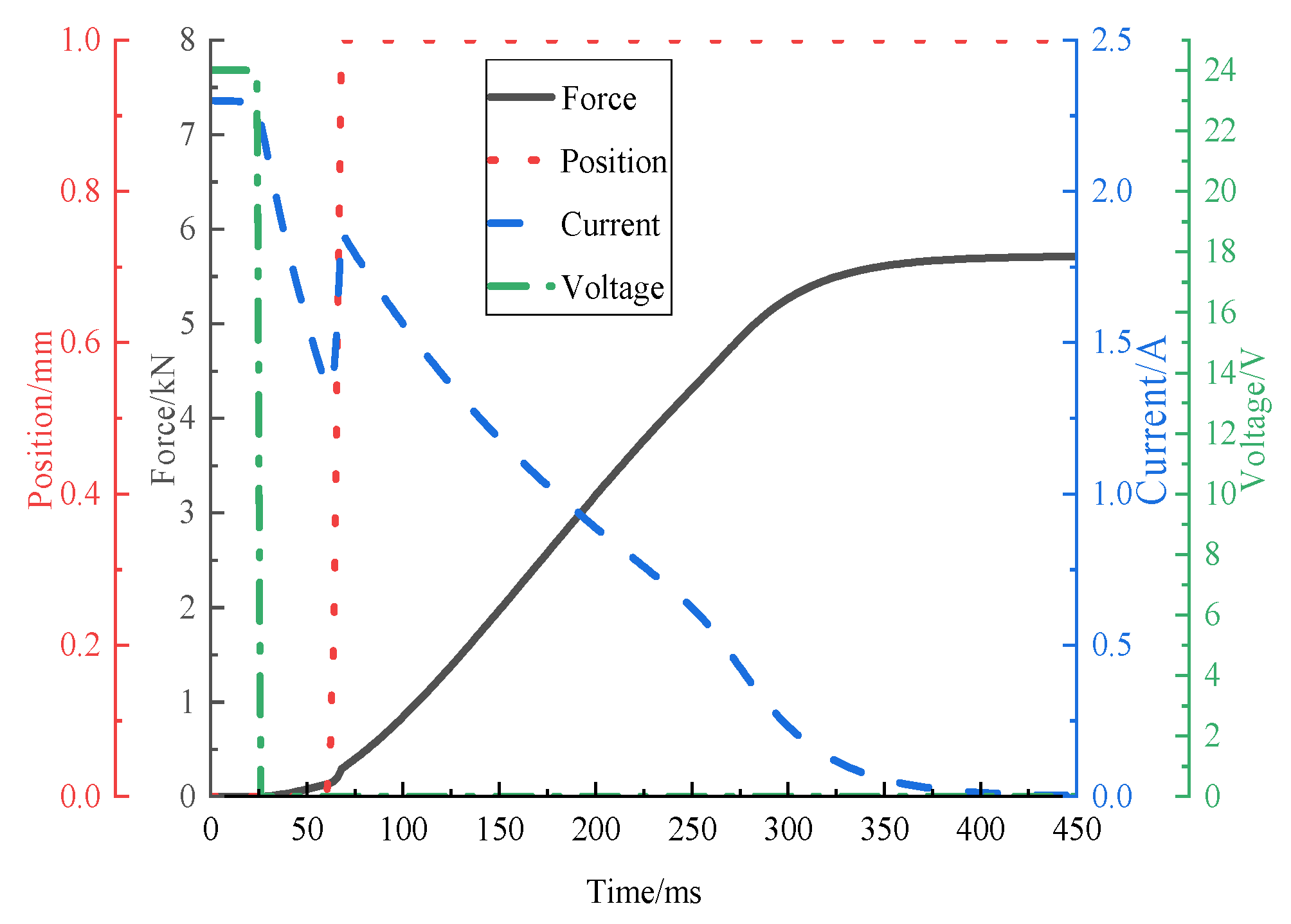
4.3. Performance Evaluation Based on Magneto-Thermal Coupling

According to the structure, material and other parameters set in the above braking structure model, the field diameter coupling was adopted to solve the electromagnetic field in Maxwell, that is, to apply excitation to the model and establish the external circuit [22]. To build the external circuit, the power supply was 24 V DC, the coil had 580 turns, 10.5 Ω, and the inductance was 1.3 H. In order to achieve accurate results, a detailed grid division is required; however, a grid division that is too fine will consume a lot of computer time and memory.
Figure 8 and Figure 9 show the flux density and flux vector distribution of the permanent magnet brake. When energized, the magnetic flux at the armature is about 0.3 T, and the magnetic flux at the junction of the inner and outer yoke is about 1.5 T.
When unenergized, the magnetic flux at the armature is approximately 1.8 T, and at the junction of the inner and outer magnetic yokes, it is approximately 2.0 T. The main magnetic circuit is I2 when the armature is energized in accordance with the requirements. At this time, the magnetic flux between the armature and the internal and external magnetic yokes is small. Therefore, the electromagnetic force is almost zero. Under the action of the leaf spring, the servo motor can work normally. The main magnetic circuit is I1 after the loss of electricity. At this time, the magnetic flux at the armature and the inner and outer magnetic yokes is close to saturation, and the magnetic flux at the junction of the inner and outer magnetic yokes is close, and the distribution is reasonable. Due to the high magnetic flux at the armature, the electromagnetic force and the brake are both high, which meets the practical requirements.
By comparing the two figures in Figure 10, it can be seen that the magnetic flux is mainly concentrated on the contact surface between the inner and outer magnetic yokes and the rotor, which is consistent with the main source of torque in the above analysis. In addition, it can be found that the magnetic flux of the outer yoke is higher than that of the inner yoke, which causes the wear of the outer yoke to be greater than that of the inner yoke, and the machining accuracy of the inner and outer yokes is inconsistent.
Figure 11 provides the simulation result of the permanent magnet brake in a transient analysis mode. From the beginning of the power outage to the armature displacement, the response time is approximately 25 ms. The dot dash line occurs because the armature moves and generates an induced current, which increases the current in the coil. The response time can be judged from this curve. At the temperature of 105 °C, the electromagnetic force is 6 kN.
Figure 12 shows the force situation of the braking armature after the temperature of the brake is stable. The electromagnetic force of the armature was recalculated by substituting the final stable temperature obtained by the magneto-thermal coupling and the one-way method into the electromagnetic field. It can be found that the final stable temperature of the magneto-thermal coupling method is approximately 105 °C, and the force of the armature is approximately 6 kN, which is about 20% less than the working temperature. The final stable temperature of the one-way method is approximately 108 °C, and the force of armature is approximately 5.7 kN. This is because the permeability of the magnetic materials will decrease with the increase in temperature.
The static braking torque of the brake is linearly related to the force on the armature, and the braking torque of the brake can be calculated using Formula (10). The braking torque calculation with a different evaluation method is shown in Table 2.

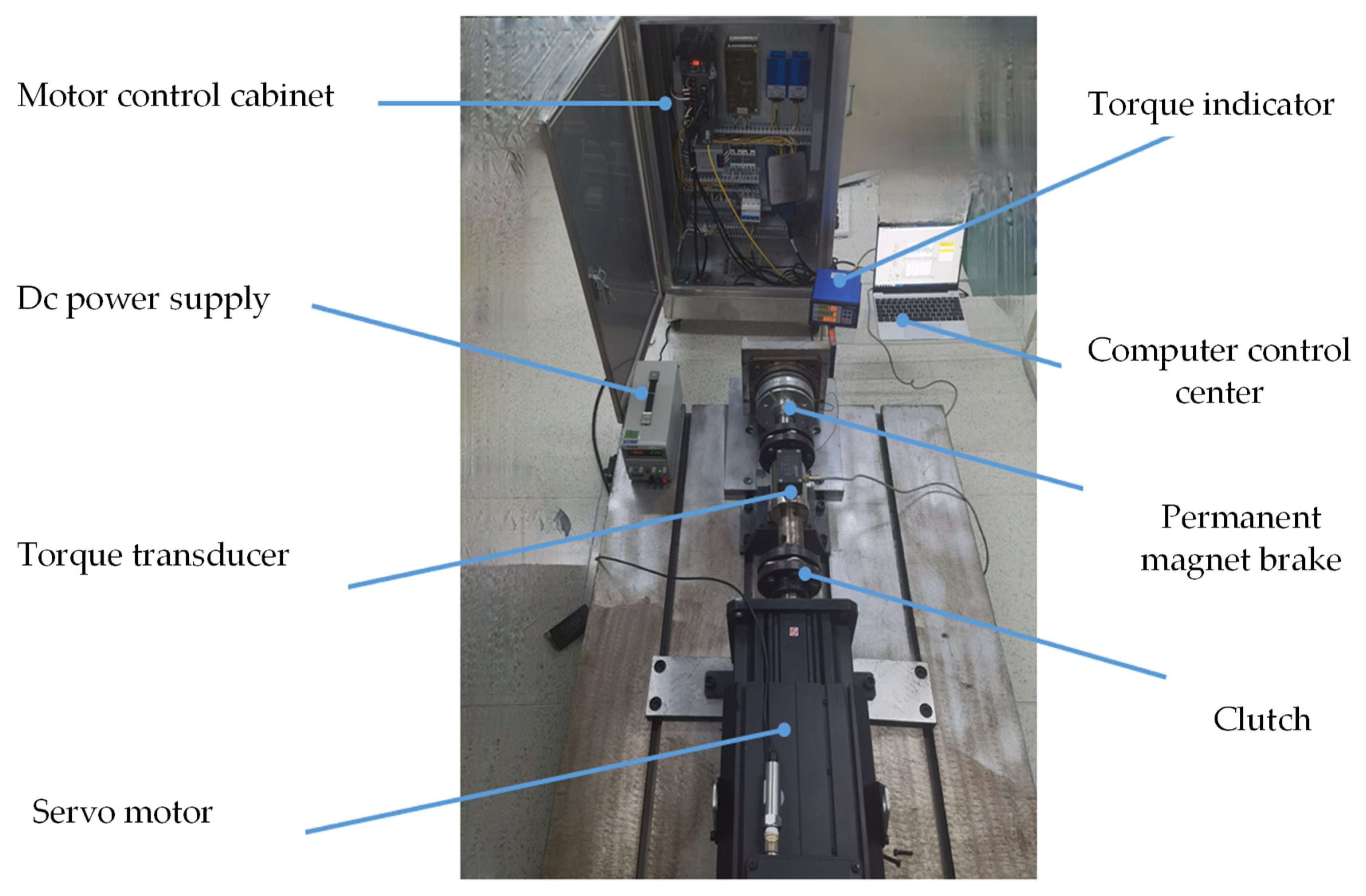
5. Experimental Validation

It is necessary to refer to the operating environment of an injection molding machine and the output parameters of a servo motor for the permanent magnet brake of an injection molding machine The specific parameters are shown in Table 3.
According to the motor parameters and the operating environment, the design requirements of the brake are shown in Table 4. Among these requirements, the room temperature condition is 25 °C, and the limit operating temperature condition of the injection molding machine is 120 °C.
The magneto-thermal coupling method was carried out for the permanent magnet brake. The braking torque, temperature distribution and temperature rise of the brake in 0–7200 s were simulated and analyzed using the magneto-thermal coupling method, and the braking torque was calculated. In order to verify the accuracy of the theoretical model, it is necessary to make a prototype model and build an experimental platform for experimental verification.

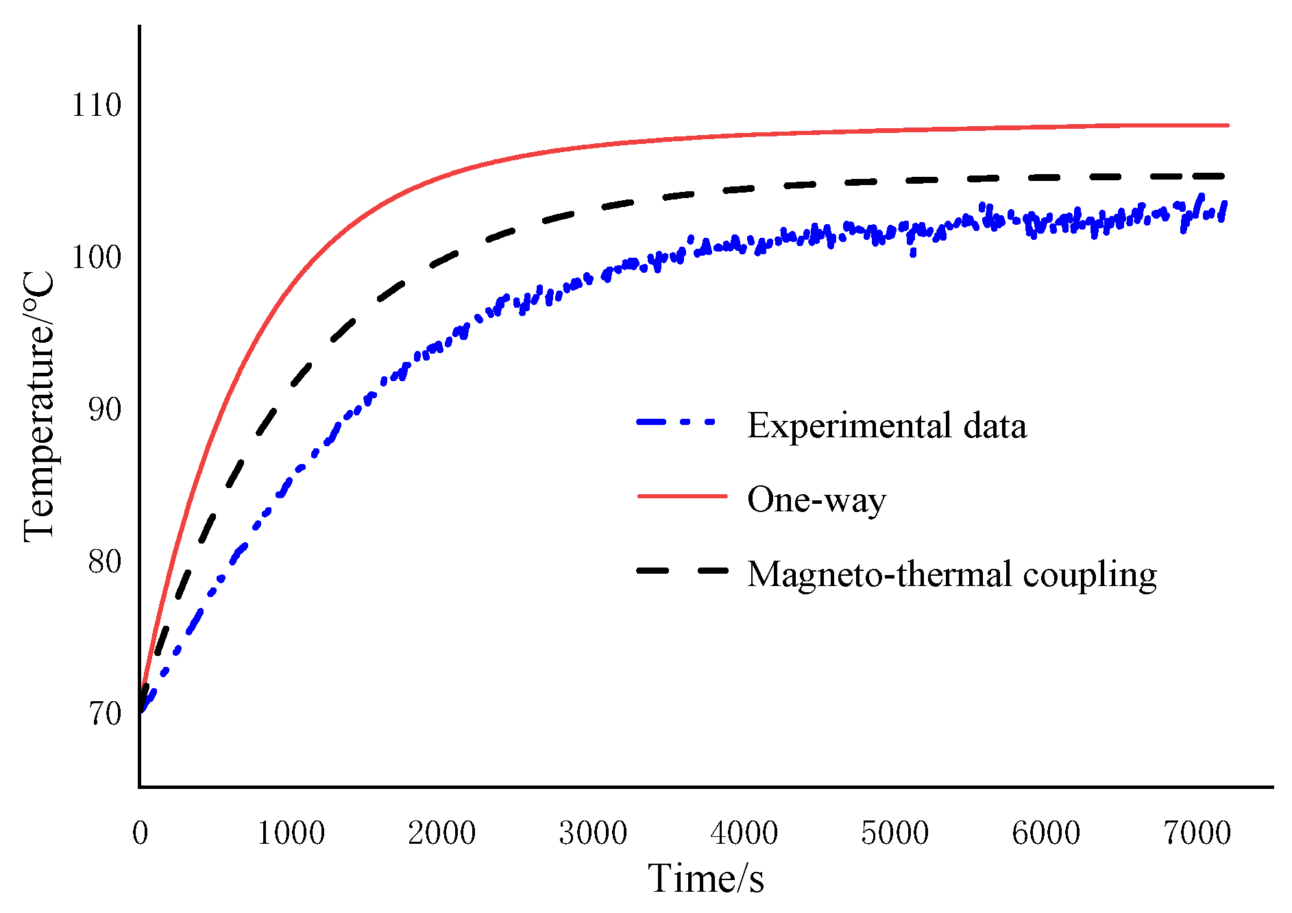
5.1. Temperature Rise Test and Model Validation

As shown in Figure 13, the permanent magnet brake to be tested was assembled on the thermostat, and the thermocouple was pasted to connect the corresponding circuit and the control system. The temperature of the incubator was set at 70 °C, and the brake was pre-heated. When the brake reached 70 °C, the 24 V DC power supply was turned on, and the temperature of the brake was monitored in real time, using the thermocouple, until the temperature became stable [23].
Figure 14 shows the comparison between the evaluation results and the experimental results of the two simulation methods. The dot dash line represents the experimental time–temperature curve. The dotted line represents the one-way method simulation time–temperature curve, and the solid line represents the magneto-thermal coupling simulation time–temperature curve. As can be seen from Figure 13, the experimental temperature tends to be stable after 6000 s, and it finally stabilizes at about 103 °C. After 5000 s, the magneto-thermal coupling method tends to be stable at about 105 °C, while the one-way method finally stabilizes at 107.5 °C. This indicates that the error of the magneto-thermal coupling method is approximately 1.9%, while the error of the one-way method is approximately 5.4%, which is only one-third of the one-way method. A comparison of the three time–temperature curves shows that the accuracy of the magneto-thermal coupling method is higher than that of the one-way method. This also verifies the feasibility of the magneto-thermal coupling method.
In the experiment, the environment of the brake is not completely adiabatic. However, it is in an ideal state in the simulation, which leads to the heat dissipation of the experiment being far greater than that of the simulation; therefore, the temperature rise rate of the simulation is also greater than that of the experiment.

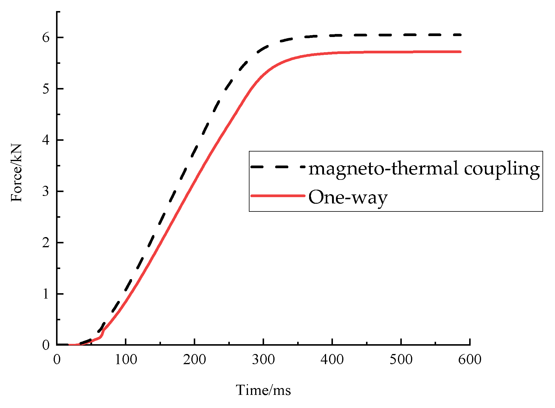
5.2. Torque Testing and Model Validation

As shown in the Figure 15, the test platform mainly included the servo motor, clutch, flywheel disk (which can be added), torque sensor, power supply, brake to be tested and the data acquisition assembly [24]. First, the brake pretreatment: in order to simulate the high-temperature working environment of an injection molding machine, the brake was placed into a baking box, and the temperature was set to 120 °C for 8 h. The brake to be tested was then installed on the test platform and fixed with a fixture to ensure that it would not move or shake. Second, the test parameters were adjusted: according to the characteristics of the brake and test requirements, the test parameters, such as test time, sampling frequency, etc., were set. A flywheel can also be added to adjust the moment of inertia to simulate the load. Finally, the test was begun: the servo motor was started, and the power was continuously increased until the brake stator and rotor had relative motion. The microcomputer then sent signals to the motor circuit and the brake control circuit, and the motor stopped rotating.
Firstly, the brake was installed on the test platform, and the flywheel was added to control the moment of inertia to simulate the load. The servo motor was started and the power was continuously increased until the brake stator and rotor had relative motion. The microcomputer sent signals to the motor circuit and the brake control circuit, and the motor stopped rotating. The data acquisition component was connected to the torque sensor through the data line to obtain the static torque information of the brake and draw the correlation curve.
Table 5 shows the static torque of the permanent magnet brake under different baking times. The time in the table represents the number of baking times. Five consecutive torque tests were carried out on the brake, which are represented by A1, A2, A3, A4 and A5. The static torque of the permanent magnet brake was up to 220 N∙m without baking, and the torque fluctuation range was small. After baking, the braking torque showed an obvious decreasing trend, with a decreasing rate of about 23%, and the fluctuation range became larger. After baking many times, the brake torque finally stabilized at about 170 N∙m, indicating that in a high-temperature working environment, the brake torque will decrease in the short term but will stabilize after a period of time. This is because the high temperature decreases the permeability of each part and increases the nonlinearity, and the remanence, Br, of the permanent magnet will also decrease. Compared with the evaluation torques in Table 1, the error for the magneto-thermal coupling method was 4.7%, and the error for the one-way method was 10%.

6. Summary and Prospect

(1) In this paper, a magneto-thermal coupling method is proposed, and the electromagnetic field model and temperature field model of the permanent magnet brake are established, respectively. Considering that the brake is in a high-temperature condition for a long time, the temperature enters a stable stage; therefore, the final temperature rise of the brake is mainly studied, while the temperature rise process is ignored. The temperature rise and temperature distribution of the permanent magnet brake are obtained by this method. By comparing the two simulation methods with the temperature rise experiment, the results show that the magneto-thermal coupling method has a higher accuracy than the one-way method, and at the operating temperature of 70 °C, the actual final temperature is about 103 °C, the final temperature of the one-way method is about 108 °C, and the final temperature of the magneto-thermal coupling method is about 105 °C. The accuracy error is reduced to 1.9%, which is only one third of the accuracy error of the one-way method.
(2) A permanent magnet brake structure scheme suitable for high torque is proposed. The permanent magnet consists of six small magnets instead of the traditional monolithic ring magnet, and a permanent magnet brake test platform that considers the operating temperature is established. The experimental results show that the torque of the brake is up to 220 N∙m at 25 °C, and the brake still has 170 N∙m torque after being roasted many times at 120 °C for 8 h, which is about 76% of the torque at 25 °C. This is because the permeability of the magnetic materials will decrease with the increase in temperature, and the permanent magnets are also demagnetized. Compared with the simulation results, the error of the torque predicted by the magneto-thermal coupling method is 4.7%, which is only half of the error of the one-way method. Therefore, according to the design requirements of the brake, it is suitable for high-operating temperature environments such as an injection molding machine.
(3) The magneto-thermal coupling model reduces the error rate of the brake temperature rise simulation, improves the prediction accuracy of brake performance in a high-temperature working environment and avoids the phenomenon of excessive braking. Of course, the magnetic-thermal coupling model still has errors. At the present stage, only the heat source coupling is considered, and the heat dissipation coefficient is analyzed as a constant. Subsequent models can take into account the effects of heat dissipation, the effects of temperature on the friction coefficient, and the effects of thermal contact resistance between components to further improve the accuracy of the model.

Author Contributions

Conceptualization, Y.W. and Y.L.; methodology, Y.W.; software, C.Z.; validation, G.W.; formal analysis, Y.L.; investigation, J.P.; resources, C.Z.; data curation, Y.W.; writing—original draft preparation, Y.L.; writing—review and editing, J.P.; visualization, Y.W.; supervision, G.W.; project administration, Y.W.; funding acquisition, Y.L. All authors have read and agreed to the published version of the manuscript.

Funding

This work was supported by the key scientific and technological innovation projects in Wenzhou, China (ZG2020027), and the National Natural Science Foundation, China (No. 72071149).

Data Availability Statement

Not applicable.

Conflicts of Interest

The authors declare no conflict of interest.

References

  1. Zhang, G.; Zhu, J.; Li, Y.; Yuan, Y.; Xiang, Y.; Lin, P.; Wang, L.; Liu, J.; Liang, L.; Deng, Z. Simulation of the Braking Effects of Permanent Magnet Eddy Current Brake and Its Effects on Levitation Characteristics of HTS Maglev Vehicles. Actuators 2022, 11, 295. [Google Scholar] [CrossRef]
  2. Wang, J.; Li, J.Q.; Gao, Z.W. A High Torque Magnetorheological Brake with Three Effective Areas. Appl. Mech. Mater. 2015, 742, 470–476. [Google Scholar] [CrossRef]
  3. Lv, M.P.; Gao, S.Y.; Wei, Y.J.; Zhang, D.; Qi, H.H. Model-Free Parallel Predictive Torque Control Based on Ultra-Local Model of Permanent Magnet Synchronous Machine. Actuators 2022, 11, 31. [Google Scholar] [CrossRef]
  4. Sinha, A.; Ischia, G.; Menapace, C.; Gialanella, S. Experimental Characterization Protocols for Wear Products from Disc Brake Materials. Atmosphere 2020, 11, 1102. [Google Scholar] [CrossRef]
  5. Ito, Y.; Oda, Y.; Narita, T.; Kato, H. Effect of Optimal Placement of Permanent Magnets on the Electromagnetic Force in the Horizontal Direction. Actuators 2018, 7, 54. [Google Scholar] [CrossRef] [Green Version]
  6. Mallik, S.; Mallik, K.; Barman, A.; Maiti, D.; Biswas, S.K.; Deb, N.K.; Basu, S. Efficiency and Cost Optimized Design of an Induction Motor Using Genetic Algorithm. IEEE Trans. Ind. Electron. 2017, 64, 9854–9863. [Google Scholar] [CrossRef]
  7. Li, Y.; Zhang, C.; Shen, Y.D. Study on electromagnetic separation mechanism of aerospace electrical Connector with large thrust range. Trans. China Electrotech. Soc. 2015, 30, 128–134. [Google Scholar]
  8. Li, S.W.; Qin, J.; Yu, L. Research on Temperature Rise of Electromagnet of Electromagnetic Clamp Disc Brake. Manuf. Upgrad. Today 2020, 10, 72–73. [Google Scholar]
  9. Dilshad, M.R.; Ashok, S.; Vijayan, V.; Pathiyil, P. An energy loss model based temperature estimation for Permanent Magnet Synchronous Motor (PMSM). In Proceedings of the 2016 2nd International Conference on Advances in Electrical, Electronics, Information, Communication and Bio-Informatics (AEEICB), Chennai, India, 27–28 February 2016; pp. 172–176. [Google Scholar]
  10. Tang, J.; Zuo, Y. The design and magnetic field analysis of a double rotor permanent magnet braking device. Processes 2022, 10, 346. [Google Scholar] [CrossRef]
  11. Li, L.; Yang, G.L.; Li, Z.X. Magneto-thermal coupling analysis of the permanent magnet eddy current brake under intensive impact load. In Proceedings of the 42nd International Conference on Vibroengineering, Shanghai, China, 19–21 October 2019; Volume 28, pp. 177–182. [Google Scholar]
  12. Fan, Y.M.; Yang, G.L. Design and analysis of magnetic circuit of permanent magnet eddy current brake. In Proceedings of the 42nd International Conference on Vibroengineering, Shanghai, China, 19–21 October 2019; Volume 28, pp. 111–117. [Google Scholar]
  13. Li, J.H.; Yang, G.L.; Sun, Q.Z. Characteristic and Thermal Analysis of Permanent Magnet Eddy Current Brake. Comput. Model. Eng. Sci. 2021, 126, 1011–1031. [Google Scholar] [CrossRef]
  14. Lee, C.-Y.; Lee, S.-J.; Tang, M.-S.; Chen, P.-C. In Situ Monitoring of Temperature inside Lithium-Ion Batteries by Flexible Micro Temperature Sensors. Sensors 2011, 11, 9942–9950. [Google Scholar] [CrossRef] [PubMed]
  15. Wang, K.Y.; He, R.; Tang, J.H.; Liu, R.C. Design and thermal analysis of a novel permanent magnet-friction integrated brake for vehicle. Therm. Sci. Belgrade 2020, 24, 1827–1834. [Google Scholar] [CrossRef]
  16. Wang, K.; Ju, H.; Yang, Y.; Guo, Z. An Optimized Permanent Magnet Brake Mechanism in Robot Joints. IEEE Access 2021, 9, 18278–18286. [Google Scholar] [CrossRef]
  17. Yasa, Y.; Sincar, E.; Ertugrul, B.T.; Mese, E. Design considerations of electromagnetic brakes for servo applications. In Proceedings of the 2014 IEEE 23rd International Symposium on Industrial Electronics (ISIE), Istanbul, Turkey, 1–4 June 2014; pp. 768–774. [Google Scholar]
  18. Woochu, K.; Eun, K.J.; Young, K.Y. Coil configuration design for the Lorentz force maximization by the topology optimization method: Applications to optical pickup coil design. Sens. Actuators A Phys. 2005, 121, 221–229. [Google Scholar]
  19. Jo, S.; Shin, H.; Chang, J. Dynamic Analysis of Surface-Mounted Permanent Magnet Type Coaxial Magnetic Gear With Damper Bar Considering Magnetic Field Modulation Effect. IEEE Access 2022, 10, 33616–33627. [Google Scholar] [CrossRef]
  20. Asif, A.; Mujeebu, M.A. Thermo-Mechanical and Structural Performances of Automobile Disc Brakes: A Review of Numerical and Experimental Studies. Arch. Comput. Methods Eng. 2018, 26, 1489–1513. [Google Scholar]
  21. Xu, Y.D.; Li, L.; Yuan, X. Magneto-thermal coupling simulation and experimental verification for a three-winding high-frequency transformer. Int. J. Appl. Electromagn. Mech. Amst. 2022, 68, 159–175. [Google Scholar] [CrossRef]
  22. Zhang, W.; Yu, Z.; Chen, X.; Huang, Q. The Magneto-Thermal Analysis of a High Torque Density Joint Motor for Humanoid Robots. In Proceedings of the 2018 IEEE-RAS 18th International Conference on Humanoid Robots (Humanoids), Beijing, China, 6–9 November 2018; pp. 112–117. [Google Scholar]
  23. Cisz, G.; Runcos, F.; Waite, S. Comparative analyses of standards temperature rise test methods for induction machines. In Proceedings of the 2009 Record of Conference Papers—Industry Applications Society 56th Annual Petroleum and Chemical Industry Conference, Anaheim, CA, USA, 14–16 September 2009; pp. 1–6. [Google Scholar]
  24. Huang, Z.Q.; Li, G.F.; Tong, Y.T.; Ouyang, W.P. Research on Dynamic Braking Torque Test Method of Brake Motor. Les Ulis EDP Sci. 2021, 257, 148–153. [Google Scholar] [CrossRef]
Figure 1. Structure of brakes. (a) Non-excited brake. (b) High-torque permanent magnet brake. (c) Three-dimensional explosion diagram of a permanent magnet brake. 1. Yoke iron. 2. Spring. 3. Friction plate. 4. Flange. 5. Disc armature. 6. Coil. 7. Inner yoke iron. 8. Permanent magnet. 9. Outer yoke iron. 10. Plate spring.
Actuators 12 00149 g001
Figure 2. Magnetic cross-sectional diagram of brake in which I1 represents the magnetic circuit between the stator and the rotor generated by the permanent magnet when it is not energized. I2 represents the magnetic circuit inside the stator generated by the permanent magnet when it is not energized. I3 represents the magnetic circuit between the stator and the rotor generated by the coil when it is energized. δ1 represents the air gap between the outer yoke and the rotor, and δ2 represents the air gap between the stator and the rotor.
Actuators 12 00149 g002
Figure 3. The one-way method flow chart.
Actuators 12 00149 g003
Figure 4. Magneto-thermal coupling flow chart.
Actuators 12 00149 g004
Figure 5. Radius of brake.
Actuators 12 00149 g005
Figure 6. Temperature distribution in the time period. (a) Brake temperature distribution at 600 s. (b) Brake temperature distribution at 1800 s. (c) Brake temperature distribution at 3600 s. (d) Brake temperature distribution at 7200 s.
Actuators 12 00149 g006
Figure 7. Magneto-thermal coupling time–temperature curve.
Actuators 12 00149 g007
Figure 8. Magnetic flux distribution when energized. (a) Magnetic flux density cloud image. (b) Magnetic flux vector distribution diagram.
Actuators 12 00149 g008
Figure 9. Magnetic flux distribution when unenergized. (a) Magnetic flux density cloud image. (b) Magnetic flux vector distribution diagram.
Actuators 12 00149 g009aActuators 12 00149 g009b
Figure 10. Magnetic flux of contact surface. (a) Magnetic flux at 0 s. (b) Magnetic flux at 0.6 s.
Actuators 12 00149 g010
Figure 11. Transient analysis of permanent magnet brake at 105 °C.
Actuators 12 00149 g011
Figure 12. Armature force simulation at different method.
Actuators 12 00149 g012
Figure 13. Working principal diagram of temperature rise test platform.
Actuators 12 00149 g013
Figure 14. Temperature rise data comparison.
Actuators 12 00149 g014
Figure 15. Torque testing platform.
Actuators 12 00149 g015
Table 1. Brake size.
ParameterValueParameterValue
Stator inner diameter/mm75Rotor inner diameter/mm148
Stator outer diameter/mm160Rotor outer
diameter/mm
161
Stator height/mm46.5Rotor height/mm27.3
Permanent magnet Thickness/mm7.5Air gap/mm1
Table 2. The brake torque calculation with different methods.
MethodBraking Torque/N∙m
Magneto-thermal coupling162
The one-way method153
Table 3. Servo motor parameters.
ParameterValue
Maximum Torque145 N∙m
Rated torque50 N∙m
Rated Speed1500 r/min
Rated power7.9 kW
Rated Frequency100 Hz
Rated current15 A
Torque53 N∙m
Rotational Inertia56 kg∙cm2
Table 4. Design requirements and brake parameters.
ParameterValue
Rated voltageDC24 V
Rated power55 W
Response time20 ms
Air clearance0.55 mm
25 °CRated current2.3 A
Coil resistance10.5 Ω
Torque170 N∙m
120 °CRated current1.66 A
Coil resistance14.5 Ω
Torque140 N∙m
Table 5. Static torque of permanent magnet brake under different baking times.
TimeA1 (N∙m)A2 (N∙m)A3 (N∙m)A4 (N∙m)A5 (N∙m)Average (N∙m)
0220.8216.9226.8216.5218.5219.903
1185.9174.4188.2187.9162.6179.784
2175.2172.1162.8180.6170.9172.315
3196.3164.6161.6168.9162.9170.864
4181.6161.0164.6173.0166.6169.369
5169.6167.8175.8173.1164.4170.14
Disclaimer/Publisher’s Note: The statements, opinions and data contained in all publications are solely those of the individual author(s) and contributor(s) and not of MDPI and/or the editor(s). MDPI and/or the editor(s) disclaim responsibility for any injury to people or property resulting from any ideas, methods, instructions or products referred to in the content.

