Abstract
In order to meet the increasing demand for high-performance and high-efficiency vehicles, this paper proposes a novel electromagnetic linear energy-reclaiming suspension technology based on the McPherson independent suspension, and analyzes its core component—ELA-ERD (Electromagnetic Linear Actuation Energy-Reclaiming Device). ELA-ERD, taking a shock absorber piston rod as the inner yoke, has a compact structure and reasonable layout by integrating the structural features of the suspension. In this paper, the design process of ELA-ERD is elaborated in detail. Aiming at the problem of over-saturation of the inner yoke magnetic density, this paper proposes a method to optimize the magnetic circuit by increasing the size of the inner yoke within the effective working area of the moving coil, thus effectively improving the electromagnetic characteristics of ELA-ERD. Moreover, the effect and potential of energy reclaiming on ELA-ERD were studied by using finite element software. The study on the energy-reclaiming law of ELA-ERD was carried out from the perspective of the changes in vibration frequency and amplitude. In addition, the internal relationship between the energy-reclaiming voltage and the vibration velocity was revealed in this work, and the energy-reclaiming voltage coefficient was defined. Through calculation of a large amount of model data, the value applicable to the designed ELA-ERD in this paper was approximately set to 4.5. This study lays an important theoretical foundation for the follow-up studies.
1. Introduction
The suspension system is the key part of the vehicle as well as an important device to ensure smooth running and stable operation of the vehicle. However, traditional suspension can only passively reduce vibration, which is far from meeting the increasing demand of high performance and high energy efficiency in the vehicle industry with rapid development momentum. To this end, active suspension and energy-reclaiming suspension technology is gradually becoming a research hotspot [1,2,3].
Active suspension has the advantages of controlling the height of the vehicle body, improving the vehicle passability, and guaranteeing the operation smoothness and stability of the vehicle [4,5]. However, active suspension requires extra energy input, which brings additional energy consumption to the vehicle and is not conducive to the improvement of vehicle energy efficiency. Under the current development of the electric-driven vehicle industry, the improvement of battery and charge-discharge technologies, as well as the vehicle energy efficiency, is of great importance. Professor Yu fan from Shanghai Jiao Tong University and his team conducted an in-depth study on the energy consumption of passive suspension and active suspension, which confirmed the high energy consumption of active suspension, and indicated the necessity of the research on energy-reclaiming suspension technology [6].
Energy conservation and environmental protection have become important themes in the development of vehicle technology. In this context, the energy-reclaiming technology of suspension has attracted more and more attention [7,8]. An energy-reclaiming suspension collects and stores kinetic energy during suspension vibration so as to improve the efficiency of vehicles. In addition, combining with active suspension, energy-reclaiming suspension can reduce the energy loss of active suspension while satisfying active control, thus further improving the comprehensive performance of the vehicle [9,10,11].
Since the 1970s, energy-reclaiming suspension technology has been developed from theoretical research to product application. This technology is becoming increasingly mature and the product has become diversified, but there is still a long way to go before realizing actual popularization and application of this technology [12,13,14]. Currently, there are several different types of energy-reclaiming suspension, including the piezoelectric energy storage type, the hydraulic energy storage type and the electromagnetic energy storage type. With the continuous improvement of the electromagnetic theory and the improvement of the performance of permanent magnet materials and high-power electronic devices, the electromagnetic energy storage type has become the most promising one. Dr. Amara G Bose, the founder of Bose Corp, MA, USA., studied the optimization of the suspension system as early as 1980, and demonstrated by theoretical analysis that electromagnetism was an effective way to achieve the desired suspension performance [15].
For the electromagnetic energy storage type, although the linear motor has less satisfactory energy-reclaiming power than rotary motor [16], it has compact structure and great advantages in motion transformation [17]. At present, the research of electromagnetic linear energy-reclaiming suspension mainly focuses on the energy-reclaiming device, controller, energy-reclaiming circuit and structure arrangement, etc. The research goal is to improve the energy efficiency and comprehensive performance of the suspension system as much as possible. Among them, the research on the energy-reclaiming device is the core, and the quality of the energy-reclaiming device will directly affect the performance of the electromagnetic linear energy-reclaiming suspension. Some scholars have put forward various working modes for electromagnetic linear energy-reclaiming device and achieved outstanding results, such as professor Gysen from Eindhoven University of Technology in the Netherlands [18,19,20], professor Vijayakumara, P B from India [21], professor Zhaoxiang Deng from Chongqing University [22,23], etc. However, there are actually few studies on the electromagnetic linear energy-reclaiming device. Even for the Bose suspension system, a successful model of electromagnetic linear energy-reclaiming suspension, the data related to its actuator have not been published yet.
It can be seen that the technical research of the electromagnetic linear energy-reclaiming suspension is still in the preliminary exploration stage, and there is still a certain distance from the actual application. Nevertheless, it still has high research value and a broad application prospect owing to its high-efficiency motion conversion, compact structure arrangement and the relatively light weight of the electromagnetic linear motor.
In view of the above studies, this paper proposes a new-type electromagnetic linear energy-reclaiming suspension technology scheme based on McPherson independent suspension. It embeds the electromagnetic linear actuation—energy-reclaiming device (ELA-ERD) device to realize active control and passive energy feed of suspension, showing advantages of compact structure, easy modification and high reliability. This paper focuses on the design, simulation and optimization of ELA-ERD. Through analysis and comparison of simulation data, this study deeply explores the energy-feeding characteristics and laws of ELA-ERD, providing an important theoretical and practical basis for the development of electromagnetic suspension technology.
2. Overall Design of the New Suspension
The new electromagnetic linear energy-reclaiming suspension proposed in this paper is based on the McPherson independent suspension structure, which has the advantages of simple structure, high reliability and low cost [24]. The design based on the McPherson independent suspension structure is beneficial to the application and promotion of the new suspension scheme.
2.1. Suspension Scheme
Figure 1 shows the structure of the new energy-reclaiming suspension. Unlike the traditional passive suspension, the electromagnetic linear energy-reclaiming suspension is equipped with an ELA-ERD at the upper end of the shock absorber to achieve active control and passive energy reclaiming. Compared with other similar active or energy-reclaiming suspension [25,26], the new suspension scheme proposed in this paper retains the shock absorber, and realizes the excellent damping effect of the whole suspension by controlling the output size and direction of the electromagnetic force of the ELA-ERD. In this way, the features and advantages of the McPherson independent suspension can be maintained. Because the shock absorber is retained, the suspension system can operate as a traditional suspension device even if the ELA-ERD does not work or fails, thereby ensuring the reliability of the suspension.
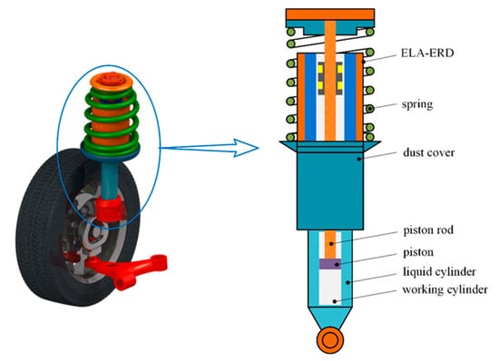
Figure 1.
The new energy-reclaiming suspension structure.
The electromagnetic linear energy-reclaiming suspension can realize passive energy reclaiming and active control while maintaining the advantages of the McPherson independent suspension, which is mainly attributed to the ELA-ERD. It can be seen from Figure 1 that ELA-ERD is mounted on a suspension shock absorber, in series with the shock absorber, and in parallel with the spring. The piston rod of the damper is fixedly connected with the coil skeleton of the ELA-ERD. The piston rod also plays a role of inner yoke. When the shock absorber moves, the coils of ELA-ERD will move synchronously with the shock absorber piston rod. Such layout realizes organic integration of ELA-ERD and suspension structure, which is more compact and reasonable.
For existing electromagnetic energy-reclaiming suspension technology [27], the electromagnetic energy-reclaiming actuator is usually arranged inside the shock absorber, which increases the difficulty in assembly and later maintenance repair and leads to shock absorber jamming, as the permanent magnet easily falls off during vibration. The technical scheme proposed in this paper can effectively solve this problem without hollowing out the shock absorber piston rod, thus avoiding the reduction in piston rod strength.
2.2. Parameters Determination
The design of suspension should be based on vehicle parameters and application requirements. An existing commercial available model is adopted in this paper, whose basic parameters are shown in Table 1.

Table 1.
Basic parameters of selected vehicle model.
After determining the vehicle parameters, the design and calculation of the suspension parameters is the basis for “Vehicle Design”, which will not be presented in this paper.
The two main components of the McPherson independent suspension are the shock absorber and the spring. On the basis of determining the basic parameters of the vehicle, the dimensions and materials of the two components can be defined through calculation, model selection and verification. Figure 2 shows the size marking of the shock absorber and spring in suspension. The specific dimensions of the shock absorber and spring are shown in in Table 2 and Table 3, respectively.
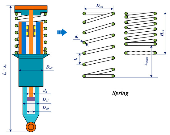
Figure 2.
Size marking of the shock absorber and spring in suspension.
Table 2.
Parameters of shock absorber.
Table 3.
Parameters of spring.
The working cylinder diameter of the shock absorber can be determined by Equation (1), prior to which the max unloading force must be calculated by Equation (2). From Equations (1) and (2), it can be known that the selection of the working cylinder diameter of the shock absorber is closely related to the vibration status and sprung mass of the vehicle.
where is the maximum allowable pressure of the working cylinder, which is set to 3.5 MPa; is the ratio of the connecting rod diameter to the cylinder diameter, which is set to for telescopic shock absorber.
where is the unloading velocity, is the damping coefficient of shock absorber, is the vibration amplitude of vehicle body, which is set to mm, is the suspension stiffness, is the sprung mass, and is the arrangement angle of shock absorber.
In order to meet the actual strength demand, the spring steel wire diameter should meet:
where is the allowable stress of spring, . is the axial load on the spring; is the spring index, which is set to in this paper; is the curvature correction factor, and the relation between and is shown as follow:
After calculation and verification, the dimension parameters of the suspension determined in this paper meet the requirements of vehicle suspension design.
3. Design of ELA-ERD
ELA-ERD is a key component to realize passive energy reclaiming and active control. The design of ELA-ERD is the core of electromagnetic linear energy-reclaiming suspension.
3.1. Basic Structure and Working Principle
Based on the previous study on ELA [28,29], this paper proposes ELA-ERD technology scheme combining the characteristics of suspension structure and long stroke, as shown in Figure 3. Considering that the moving coil type is easier to be controlled and the mover mass is smaller than the moving iron type, the ELA-ERD in this paper adopts the moving coil type.
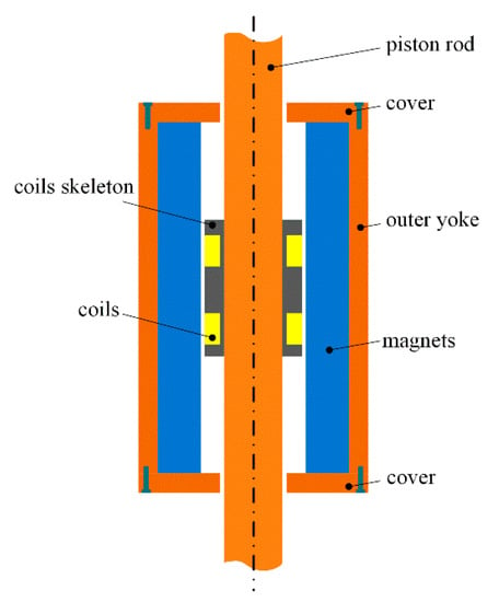
Figure 3.
Schematic diagram of ELA-ERD structure.
As shown in Figure 3, ELA-ERD is mainly composed of external magnetic yoke, permanent magnets, moving coils and inner core. The piston rod of the shock absorber is used as the inner yoke of the ELA-ERD. The coil skeleton is fixedly connected with the piston rod. When the suspension vibrates and the shock absorber piston reciprocates, the coil of ELA-ERD moves synchronously, cutting the magnetic induction line to generate induction current.
The mechanism of generating magnetic induction voltage by moving coils cutting the magnetic induction line can be expressed by Equation (5):
where is the induced voltage, is the magnetic induction intensity, is the effective coil length for cutting magnetic line, and is the cutting speed of the coil. To meet Equation (5), , , must be perpendicular to each other, which is an ideal state. However, angle deviations will be inevitably caused in the actual process. The mechanism of energy reclaiming is analyzed according to Equation (5).
As can be seen from Equation (5), higher induction voltage requires stronger magnetic induction intensity. For ELA-ERD, it is necessary to increase the magnetic induction intensity in the radial direction of the working domain of the mover as much as possible. Therefore, the Halbach array pattern is adopted for the permanent magnet of ELA-ERD, which is conducive to enhancing one side’s magnetic field while weakening the other side’s magnetic field [30]. The working principle of the Halbach array pattern is shown in Figure 4.
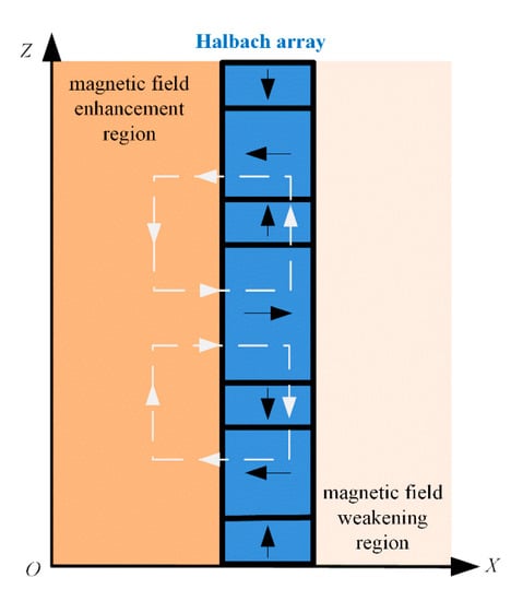
Figure 4.
Working principle of Halbach array pattern.
3.2. Determination of Dimension and Material
In order to achieve reasonable layout and avoid motion interference, the overall dimension and motion stroke of the ELA-ERD are limited by the size of the McPherson independent suspension.
In order to avoid the impact failure in the compression process, the height of ELA-ERD should be lower than the height of the suspension spring when compressed to the bottom, i.e.,
Through calculation, it can be known that , in this paper .
The outer diameter of ELA-ERD is identical to that of the shock absorber dust cover, both of which are set to 40 mm in this study. In order not to interfere with the normal operation of the suspension shock absorber, the motion travel of the ELA-ERD should be slightly larger than that of the shock absorber. As the shock absorber travel is 100 mm, so the motion travel of ELA-ERD is set to 110 mm.
Air gap thickness is an important parameter affecting the electromagnetic performance of the ELA-ERD, a too big or too small value of will be inconducive to the full utilization of magnetic energy and performance improvement of ELA-ERD. The determination of air gap thickness is based on the magnetic circuit design of ELA-ERD, which is closely related to the magnetic circuit structure, permanent magnets size and working point of the magnets, as shown in Equation (7).
Where is the gap flux density. is the magnetic energy product at working point of permanent magnet, is the permanent magnet volume, is the air gap volume, is the permeability of vacuum, is the magnetic leakage coefficient, and is the magnetic reluctivity.
In the design of magnetic circuit, the air gap thickness is determined through multiple calculations. According to previous design experience on the linear motor, current structural features of ELA-ERD, the layout pattern of permanent magnets and materials, the air gap thickness is preliminarily set to 0.15 mm in this study. After the air gap thickness is determined, the permanent magnets thickness and the external magnetic yoke thickness in the radial direction of ELA-ERD can be determined successively.
In the axial direction, ELA-ERD is in a symmetrical arrangement, so there is
where is the overall axial height of the permanent magnet, is the axial thickness of end cover.
At this point, the structural dimension of ELA-ERD has been basically determined, and the specific parameters are shown in Table 4.
Table 4.
Basic dimensional parameters of ELA-ERD.
The material of each component of ELA-ERD is shown in Table 5. To obtain better magnetic effect, steel-1008 with high strength and good magnetic property was selected for the outer cover, end cover and inner yoke of ELA-ERD. The permanent magnets are made of the sintered NdFeB N45 H with high remanent magnetism and high temperature resistance, which can provide a powerful magnetic field for ELA-ERD. The coils are made of copper-core enameled wire, which can maximize the winding coverage.
Table 5.
Material of each component of ELA-ERD.
3.3. Winding Design
According to the ELA-ERD structure shown in Figure 3, the height of the moving coil skeleton is affected by the device stroke. In this paper, the height of the moving coil skeleton can be calculated by Equation (9).
The arrangement of windings is closely related to the array and dimension of permanent magnets. As can be seen from Figure 5a, as the coil skeleton height span consists of three radial permanent magnets, three groups of windings were arranged in order to realize maximum energy-reclaiming effect. Further research can be carried out on the winding-permanent magnet arrangement, which will be of great significance to the performance improvement of ELA-ERD, and will not be discussed in this paper.
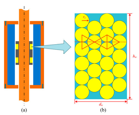
Figure 5.
Winding arrangement and coil winding: (a) ELA-ERD; (b) Winding.
The moving coils are winded enameled wire. In order to improve the current density of the winding as much as possible, the coils should be winded as tightly as possible, and the winding state is shown in Figure 5b, from which we can see that the winding meets the following relationship:
According to Equations (10) and (11), given the height and thickness of the winding, enameled wire radius and the winding number can be obtained, where is the number of enameled wire winding layers, which is set to in this paper. After determining the enameled wire radius , the maximum current or current density can be defined by referring to the characteristic parameter table of enameled wire, and reverse design of the ELA-ERD windings can be realized according to the maximum current limit.
After the winding parameters are determined, the resistance value of the windings of the ELA-ERD can be obtained according to the resistance formula (12) of copper.
where is the copper resistivity, is the total length of enameled wire in the windings, is the cross-sectional area of a single-stranded copper-core enameled wire, and is the effective median diameter of the windings.
3.4. Improvement of Magnetic Circuit
Magnetic circuit design directly determines the performance of the motor. In the magnetic circuit design process, the magnetic circuit needs to be modified and improved continuously. The magnetic circuit of the ELA-ERD designed in this paper needs to be analyzed and optimized as well. The traditional calculation method is very inefficient. Finite element simulation software is an important tool for rapid and accurate evaluation and feedback of motor magnetic circuit design, based on which we can simulate and calculate many complex problems.
In this paper, Ansoft Maxwell was used to model and simulate the ELA-ERD. Figure 6 shows the cloud diagram of magnetic induction intensity distribution obtained by simulation.
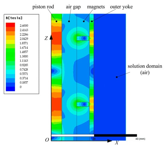
Figure 6.
Finite element model and magnetic induction intensity distribution cloud map of ELA-ERD.
As can be seen from Figure 6, the magnetic induction intensity at the inner yoke (i.e., piston rod) position is seriously saturated, while the magnetic density in the working area of the moving coils is far from the ideal value. This indicates that the inner yoke is too small, which leads to the waste of a large part of magnetic energy, thus damping the output performance. Therefore, the magnetic circuit needs to be improved. Since the diameter of the piston rod has already been determined at the time when the selection design of shock absorber type is carried out, its size is not changeable. If the overall size of the ELA-ERD is reduced to match the small inner yoke, it is not conducive to maximizing the use of suspension layout space, and the overall performance of the ELA-ERD will be greatly reduced. Under the premise of keeping the current inner yoke size unchanged and not reducing the overall external diameter of ELA-ERD, the permanent magnet size is bound to be larger so as to achieve a more ideal working domain magnetic density, and the work domain thickness will be compressed. This will only aggravate the over-saturation of the inner yoke magnetic density, resulting in a large amount of magnetic energy waste.
Based on the above analysis, it can be known that a too small inner yoke is the root cause. Aiming at this problem, this paper adopts an improvement scheme, as shown in Figure 7. A part of the same material is added at the junction of the moving coils and the inner yoke, which can form a good magnetic circuit within the effective working range of the moving coils, increasing the magnetic density at the position of the moving coils, and effectively alleviating the over-saturation of the inner yoke magnetic density.
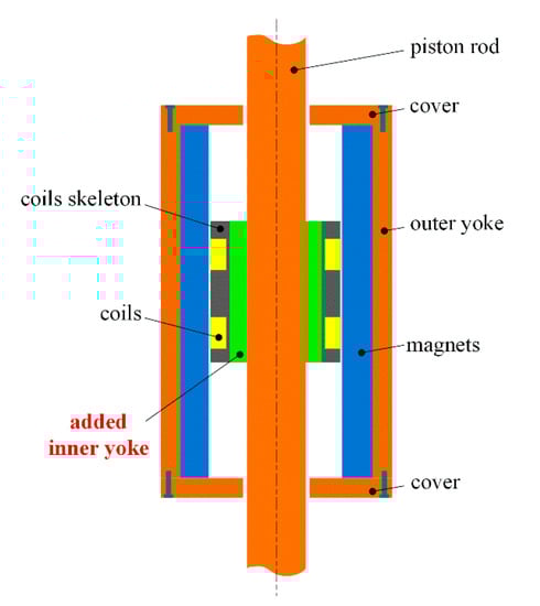
Figure 7.
The structure diagram of improved ELA-ERD.
Similarly, with the help of Ansoft Maxwell software, the finite element model of the improved ELA-ERD was reconstructed and simulated. The magnetic induction intensity distribution of the improved scheme can be obtained, as shown in Figure 8.
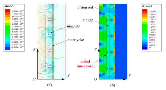
Figure 8.
Distribution of magnetic force lines and magnetic induction intensity of ELA-ERD after improvement: (a) Distribution of magnetic force lines; (b) Distribution of magnetic induction intensity.
As shown in Figure 8, the magnetic induction intensity at the improved moving coils working area is significantly enhanced and in a more uniform distribution, and the magnetic density saturation of the inner yoke is significantly alleviated as well. In addition, as the inner yoke of ELA-ERD is replaced by the shock absorber piston rod, which runs through the whole device, certain magnetic leakage will be inevitably resulted. It can be seen from Figure 8 that the magnetic leakage situation at both ends of the inner yoke of the improved ELA-ERD has been significantly improved.
4. Analysis of Energy-Reclaiming Characteristics of ELA-ERD
After completing the design of ELA-ERD, it is necessary to carry out in-depth analysis of its energy-reclaiming characteristics. This paper mainly studies the ELA-ERD from energy-reclaiming effect and the law of energy reclaiming.
4.1. Analysis of Energy-Reclaiming Effect
First, the energy-reclaiming effect of the designed ELA-ERD needs to be verified. With the help of Ansoft Maxwell, modeling, mesh generation and excitation setting of ELA-ERD were carried out, in which the excitation was based on motion as input, and the simulation results of the model were obtained through post-processing.
The energy reclaiming of ELA-ERD was analyzed by taking the motion of the moving coils as input. However, the vibration is irregular in the actual operation of the vehicle. In order to facilitate the research and subsequent regular analysis, this paper takes the simple harmonic motion as the vibration input in the simulation process. The kinematic equation of the ELA-ERD moving coils is shown in Equation (13):
where is the vibration amplitude, and the vibration frequency The offset frequency of the front suspension is kept at 1–1.6 Hz when full load is required for passenger vehicles. Under actual working conditions, slight jolt will increase the vibration of the vehicle suspension. In this paper, the simple harmonic vibration with vibration frequency of 2 Hz and vibration amplitude of 50 mm was preliminarily selected as the motion inputs of the model. The output characteristic curve can be obtained through simulation, as shown in Figure 9.
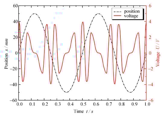
Figure 9.
The vibration and energy-reclaiming voltage curve of ELA-ERD under vibration frequency of 2 Hz and vibration amplitude of 50 mm.
As can be seen from Figure 9, the output curve of energy-reclaiming voltage of ELA-ERD shows a periodical change. The peak value of the energy-reclaiming voltage reached 4 V under the simple harmonic input with vibration amplitude of 50 mm and vibration frequency of 2 Hz. Combining the resistance of the windings of ELA-ERD, the energy-reclaiming power under the current vibration condition was calculated to be about 42 W, which is also the energy-reclaiming power of the single side suspension. In the actual operation process, slight unevenness of road will increase the vibration of vehicle, and four wheels will all vibrate, so the electromagnetic linear energy-reclaiming suspension has a considerable potential for energy reclaiming.
4.2. Study of Energy-Reclaiming Law
The change of vibration input is a key issue that should be taken into consideration when studying the energy-reclaiming law of ELA-ERD. According to Equation (13), amplitude and frequency are the two most important parameters affecting the state of simple harmonic vibration. The parametric analysis of the motion input of ELA-ERD was carried out, and the change of energy-reclaiming voltage under two different vibration frequencies and vibration amplitudes was observed, as shown in Figure 10 and Figure 11.
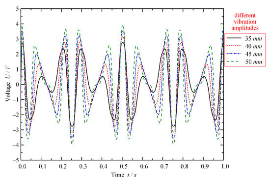
Figure 10.
Vibration and energy-reclaiming voltage curve of ELA-ERD under different vibration amplitudes.
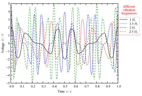
Figure 11.
Vibration and energy-reclaiming voltage curve of ELA-ERD under different vibration frequencies.
As can be seen from Figure 10 and Figure 11, the energy-reclaiming voltage of ELA-ERD changes periodically, and the curve shapes are almost identical, indicating stable output of the energy-reclaiming voltage. As can be seen from Figure 10, the energy-reclaiming voltage increases significantly with the increase in vibration amplitude. As can be seen from Figure 11, the increase in vibration frequency can increase the energy-reclaiming voltage in terms of both intensity and amplitude. In conclusion, the vibration frequency increase or vibration amplitude increase leads to the increase in energy-reclaiming voltage, as evidenced by the relationship between the absolute average value of the energy-reclaiming voltage and vibration frequency and vibration amplitude as shown in Figure 12.
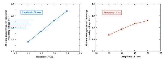
Figure 12.
Relationship between the absolute average value of the energy-reclaiming voltage and vibration frequency and vibration amplitude.
The change of vibration frequency and amplitude eventually leads to the change of vibration velocity. However, the magnitude of vibration velocity is the real factor affecting the energy-reclaiming voltage according to ELA-ERD’s energy-reclaiming principle Equation (5) that is established under an ideal state. In ELA-ERD, the magnitude and direction of the magnetic induction at the moving coils working area vary from position to position. In the process of reciprocating motion of the moving coils, both and are difficult to determine. Therefore, it is necessary to carry out studies from other perspectives.
Under working conditions, the vibration velocity curve can be obtained by taking the derivative of the vibration displacement curve. The curves of vibration velocity and energy-reclaiming voltage are compared, as shown in Figure 13a. Due to the varying direction of the moving coil when cutting the magnetic induction line as well as the changing direction of the magnetic field, the direction of energy-reclaiming voltage is also changing, which cannot be observed from Figure 13a. Figure 13b shows the curve after taking the absolute value of vibration velocity and energy-reclaiming voltage with consideration on the influence of direction. It is obvious from Figure 13b that the overall curve trend of energy-reclaiming voltage is well consistent with that of vibration velocity.
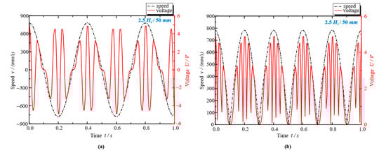
Figure 13.
The relation between the curve of energy-reclaiming voltage and the curve of vibration velocity under vibration frequency of 2.5 Hz and vibration amplitude of 50 mm: (a) The curves of vibration velocity and energy-reclaiming voltage; (b) The curve after taking the absolute value of vibration velocity and energy-reclaiming voltage.
Figure 13 shows the working condition where the vibration frequency is 2.5 Hz and the vibration amplitude is 50 mm, which is of no universal significance. Through conducting the above process under other working conditions, the relationship shown in Figure 14 can be obtained. Figure 14 mainly lists four working conditions, and it can be clearly seen that the above regular features are presented regardless of the vibration frequency and vibration amplitude.
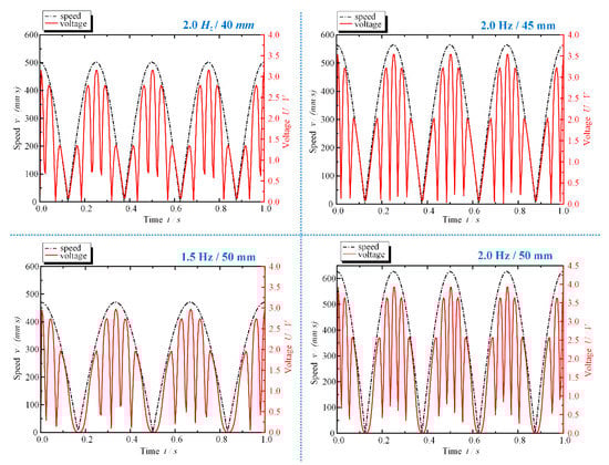
Figure 14.
The relation between the curve of energy-reclaiming voltage and the curve of vibration velocity under four working conditions.
As can be seen from the relation between the curve of energy-reclaiming voltage and the curve of vibration velocity, there is a certain proportional relation between the absolute value of the vibration velocity and the energy-reclaiming voltage. To explore the numerical relationship between them, we averaged the absolute value of the energy-reclaiming voltage and the vibration velocity, and calculated the ratio of the two, i.e., . Table 6 shows the ratio under different vibration frequencies and vibration amplitudes.
Table 6.
The ratio under different vibration frequencies and vibration amplitudes.
To find the rule and avoid the accidental factors, Table 6 shows the values of under 16 different working conditions. It can be found that no matter how the vibration frequency and amplitude change, the value of under different conditions basically remains around 4.5. In this paper, is defined as the energy-reclaiming voltage coefficient of ELA-ERD.
where is the mean absolute value of the energy-reclaiming voltage,
is the mean absolute value of the vibration velocity, is the displacement function of the vibration of ELA-ERD moving coils. From Table 6, it can be known that the energy voltage reclaiming coefficient of ELA-ERD designed in this paper is .
According to Equation (14), it can be known that the energy-reclaiming voltage of ELA-ERD is proportional to the vibration velocity. According to Equation (14), as long as the time-domain data of the vibration amplitude of shock absorber piston of the electromagnetic linear energy-reclaiming suspension can be obtained, the magnitude of the energy-reclaiming voltage of ELA-ERD can be estimated, which lays a theoretical foundation for further study of ELA-ERD.
5. Conclusions
The following conclusions are drawn from this paper:
- A novel electromagnetic linear energy-reclaiming suspension based on the McPherson independent suspension is proposed in this study. The suspension has the advantages of compact structure, easy modification, and high reliability. Even if ELA-ERD fails, the normal operation of the suspension will not be affected, showing obvious advantages over other electromagnetic energy-reclaiming suspension.
- The ELA-ERD applied to the novel suspension was designed to realize passive energy reclaiming and active control. This device adopts the piston rod of the shock absorber as the inner yoke and organically integrates the structural characteristics of the suspension. The permanent magnets are arranged in Halbach array pattern to enhance the magnetic density within the work field.
- To solve the problem of magnetic density oversaturation of the inner yoke in the initial design phase, the magnetic circuit of ELA-ERD is optimized by increasing the size of the inner yoke in the effective working area of the moving coils. The simulation results show that this measure effectively improved the electromagnetic performance of ELA-ERD.
- The simulation analysis showed that the energy-reclaiming power of ELA-ERD reached 42 W under vibration amplitude of 50 mm and vibration frequency of 2 Hz. Therefore, the electromagnetic linear energy-reclaiming suspension with ELA-ERD has considerable potential for energy reclaiming.
- The factors influencing the energy-reclaiming law of ELA-ERD were analyzed from the perspectives of the changes of vibration amplitude and vibration frequency, and then the most fundamental influencing factor, vibration velocity, was further explored. According to Equation (14), the energy-reclaiming voltage coefficient was defined. Through comparison of a large number of data, the energy-reclaiming voltage coefficient of the ELA-ERD designed in this paper was derived, which lays a theoretical foundation for the subsequent research of ELA-ERD.
Although achieving progress and conclusions, the research on electromagnetic linear energy-reclaiming suspension is still in the preliminary stage. Further research should be carried out on the improvement of suspension energy-reclaiming power and reclaiming efficiency as well as on the implementation of active control, so as to promote the application of electromagnetic linear energy-reclaiming suspension and enhance the development of vehicle suspension technology.
Author Contributions
Conceptualization, J.D. and L.C.; methodology, J.D., L.C. and Y.Q.; software, formal analysis and investigation, J.D., Y.Q., C.W. and J.Z. (Jianhui Zhu); resources, J.D., L.C. and C.W.; data curation, J.D., J.Z. (Jun Zhu) and J.Z. (Jingxuan Zhu); writing—original draft preparation, J.D., Y.Q., J.Z. (Jianhui Zhu) and J.Z. (Jun Zhu); writing—review and editing, J.D., L.C. and Y.Q. All authors have read and agreed to the published version of the manuscript.
Funding
This work was supported by the National Natural Science Foundation of China (Grant No. 51605183, 51975239), and the Natural Science Foundation for Jiangsu Colleges and Universities (Grant No. 21KJB480005).
Institutional Review Board Statement
Not applicable.
Informed Consent Statement
Not applicable.
Data Availability Statement
Not applicable.
Conflicts of Interest
The authors declare no conflict of interest.
References
- Abdelkareem, M.A.; Xu, L.; Ali, M.K.A.; Elagouz, A.; Mi, J.; Guo, S.; Liu, Y.; Zuo, L. Vibration energy harvesting in automotive suspension system: A detailed review. Appl. Energy 2018, 229, 672–699. [Google Scholar] [CrossRef]
- Zheng, P.; Gao., J.; Wang, R.; Dong, J.; Diao, J. Review on the Research of Regenerative Shock Absorber. In Proceedings of the 2018 24th International Conference on Automation and Computing (ICAC), Newcastle upon Tyne, UK, 6–7 September 2018; pp. 1–12. [Google Scholar]
- Zhang, Y.; Guo, K.; Wang, D.; Chen, C.; Li, X. Energy conversion mechanism and regenerative potential of vehicle suspensions. Energy 2017, 119, 961–970. [Google Scholar] [CrossRef]
- Čorić, M.; Deur, J.; Kasać, J.; Tseng, H.E.; Hrovat, D. Optimisation of active suspension control inputs for improved vehicle handling performance. Veh. Syst. Dyn. Int. J. Veh. Mech. Mobil. 2016, 54, 1574–1600. [Google Scholar] [CrossRef]
- Gong, M.; Yan, X. Robust Control Strategy of Heavy Vehicle Active Suspension Based on Road Level Estimation. Int. J. Automot. Technol. 2021, 22, 141–153. [Google Scholar] [CrossRef]
- Zheng, X.; Yu, F. Study on the potential benefits of an energy-regenerative active suspension for vehicles. SAE Trans. 2005, 114, 242–245. [Google Scholar]
- Lato, T.; Zhao, H.; Lin, Z.; He, Y. An Energy-Regenerative Suspension System. In Proceedings of the ASME 2018 International Mechanical Engineering Congress and Exposition IMECE 2018, Pittsburg, PA, USA, 9–15 November 2018. [Google Scholar]
- Zheng, P.; Wang, R.; Gao, J. A Comprehensive Review on Regenerative Shock Absorber Systems. J. Vib. Eng. Technol. 2020, 8, 225–246. [Google Scholar] [CrossRef]
- Long, G.; Ding, F.; Zhang, N.; Zhang, J.; Qin, A. Regenerative active suspension system with residual energy for in-wheel motor driven electric vehicle. Appl. Energy 2020, 260, 114180. [Google Scholar] [CrossRef]
- Salman, W.; Qi, L.; Zhu, X.; Pan, H.; Zhang, X.; Bano, S.; Zhang, Z.; Yuan, Y. A high-efficiency energy regenerative shock absorber using helical gears for powering low-wattage electrical device of electric vehicles. Energy 2018, 159, 361–372. [Google Scholar] [CrossRef]
- Fu, C.; Lu, J.; Ge, W.; Tan, C.; Li, B. A Review of Electromagnetic Energy Regenerative Suspension System & Key Technologies. Comput. Model. Eng. Sci. 2022, 135. [Google Scholar] [CrossRef]
- Tvrdić, V.; Podrug, S.; Jelaska, D.; Perkušić, M. A Concept of the Novel Regenerative Hydraulic Suspension: The Prototype Description. In Proceedings of the 2018 3rd International Conference on Smart and Sustainable Technologies (SpliTech), Split, Croatia, 26–29 June 2018; pp. 1–6. [Google Scholar]
- He, X.; Xiao, G.; Hu, B.; Tan, L.; Tang, H.; He, S.; He, Z. The applications of energy regeneration and conversion technologies based on hydraulic transmission systems: A review. Energy Convers. Manag. 2020, 205, 0196–8904. [Google Scholar] [CrossRef]
- Dai, J.G.; Wang, C.; Liu, Z.F.; Zhu, J.H.; Hu, X.M. Review of energy reclaiming suspension technology. Sci. Technol. Eng. 2018, 18, 131–139. [Google Scholar]
- Bose Automotive Systems (China). BOSE’s innovative suspension system. Auto Accessories 2012, 12, 38–39. [Google Scholar]
- Boduroglu, A.; Gulec, M.; Demir, Y.; Yolacan, E.; Aydin, M. A New Asymmetric Planar V-Shaped Magnet Arrangement for A Linear PM Synchronous Motor. IEEE Trans. Magn. 2019, 55, 1–5. [Google Scholar] [CrossRef]
- Lv, X.; Ji, Y.; Zhao, H.; Zhang, J.; Zhang, G.; Zhang, L. Research Review of a Vehicle Energy-Regenerative Suspension System. Energies 2020, 13, 441. [Google Scholar] [CrossRef]
- Gysen, B.L.; Paulides, J.J.; Janssen, J.L.; Lomonova, E.A. Active electromagnetic suspension system for improved vehicle dynamics. IEEE Trans. Veh. Technol. 2010, 59, 1156–1163. [Google Scholar] [CrossRef]
- Gysen, B.L.; van der Sande, T.P.; Paulides, J.J.; Lomonova, E.A. Efficiency of a regenerative direct-drive electromagnetic active suspension. IEEE Trans. Veh. Technol. 2010, 60, 1384–1393. [Google Scholar] [CrossRef]
- Gysen, B.L.; Janssen, J.L.; Paulides, J.J.; Lomonova, E.A. Design aspects of an active electromagnetic suspension system for automotive applications. In Proceedings of the Industry Applications Society Meeting, Houston, TX, USA, 4–8 October 2009; IEEE: New York, NY, USA, 2009; pp. 1–8. [Google Scholar]
- Vijayakumara, P.; Mallikarjuna, D.C.; Suresh, R. Generating of power suspension shock absorber. Int. J. Adv. Eng. Res. Dev. 2017, 4, 713–721. [Google Scholar]
- Deng, Z.; Lai, F. Vehicle Active suspension Electromagnetic linear actuator Finite element analysis. Chin. J. Mech. Eng. Engl. Ed. 2011, 47, 121–128. [Google Scholar] [CrossRef]
- Chen, X.; Luo, H.; Deng, Z. Design of an energy-regenerative suspension control systemusing linear motor and energy recovery analysis. J. Vib. Shock. 2012, 31, 124–129. [Google Scholar]
- Deubel, C.; Prokop, G. Friction of a MacPherson suspension system at various load cases. J. Vib. Control. 2022, 2022, 10775463221140324. [Google Scholar] [CrossRef]
- Xiao-dong, S.U.N.; Feng, C.A.I.; Ying-feng, C.A.I.; Long, C.H.E.N. Improved Model Predictive Thrust-force Control of Linear Motors for Active Suspensions. China J. Highw. Transp. 2021, 34, 85–100. [Google Scholar]
- Yang, M.; Yu, J.; Guo, Y. Present Situation and Development Tendency of Shock Absorbers in Vehicle Suspensions. Eng. Test 2019, 59, 97–100 + 103. [Google Scholar]
- Yu, L.; Zhang, M.; Xue, W.; Luo, W.; He, J.; Tian, H. A Comprehensive Review of Permanent Magnet Synchronous Linear Motors in automotive electromagnetic suspension system. In Proceedings of the 2021 IEEE 4th Advanced Information Management Communicates, Electronic and Automation Control Conference (IMCEC), Chongqing, China, 18–20 June 2021; pp. 792–796. [Google Scholar]
- Dai, J.; Zhao, Z.; Xu, S.; Wang, C.; Zhu, J.; Fan, X. Inhibition of iron loss of the inner yoke in electromagnetic linear actuator. IET Electr. Power Appl. 2019, 13, 419–425. [Google Scholar] [CrossRef]
- Dai, J.; Xia, J.; Wang, C.; Xu, S. Thermal analysis of an electromagnetic linear actuator. Adv. Mech. Eng. 2017, 9, 1687814017745387. [Google Scholar] [CrossRef]
- Li, Z.; Wu, Q.; Liu, B.; Gong, Z. Optimal Design of Magneto-Force-Thermal Parameters for Electromagnetic Actuators with Halbach Array. Actuators 2021, 10, 231. [Google Scholar] [CrossRef]


Disclaimer/Publisher’s Note: The statements, opinions and data contained in all publications are solely those of the individual author(s) and contributor(s) and not of MDPI and/or the editor(s). MDPI and/or the editor(s) disclaim responsibility for any injury to people or property resulting from any ideas, methods, instructions or products referred to in the content. |
© 2023 by the authors. Licensee MDPI, Basel, Switzerland. This article is an open access article distributed under the terms and conditions of the Creative Commons Attribution (CC BY) license (https://creativecommons.org/licenses/by/4.0/).