Abstract
In order to enhance compressor efficiency and meet the requirements of energy conservation and environmental protection, this study designed a direct-drive compressor with an electromagnetic linear actuator. Starting with the structural design and performance analysis of the linear compressor, the working process of the moving-coil linear compressor was analyzed. The basic performance of the designed moving-coil linear motor was simulated and analyzed using the Maxwell software, while the overall performance of the linear compressor was simulated and analyzed using the Simulink software to verify the feasibility of controlling a linear compressor via the direct drive of a linear motor.
1. Introduction
Compressors play an important role in modern machinery. Currently, compressors extensively used in production and daily life include crankshaft connecting rod type, reciprocating type, and rotary type, among others. Despite the mature technology and a complete industrial chain, such compressors have a low mechanical efficiency [1]. By using an electromagnetic actuator to directly drive the piston, a linear compressor conducts reciprocating linear motion in the cylinder, with the mechanical efficiency increasing by 15~25%, thus greatly contributing to energy conservation [2]. In addition, a linear compressor has the advantages of small volume, long service life, low noise, controllable piston stroke, and almost zero lateral force [3]. Nonetheless, research on linear compressors is mainly carried out by large technology companies and scientific research institutes in Japan, South Korea, the United States, etc. Sunpower of the United States, LG of South Korea, and Panasonic of Japan have attained remarkable achievements in this respect [4].
Compared to foreign countries, domestic research on linear compressors in China is disadvantageous in both theory and technology. With the advancement of science and technology, domestic scholars have started to study linear compressors after being aware of their importance. Since the 1980s, China has introduced foreign linear compressor technology and carried out extensive experimental research and product development on this basis. However, due to the weak theoretical foundation and backward manufacturing technology, domestic production of compressors has low mechanical efficiency and high cost, and cannot replace traditional compressors [5].
Based on the Redlich moving-magnet linear motor structure, Gao Yao et al. designed a linear compressor using the vector analysis method, which has the advantages of low weight and high efficiency [6]. Fang Xueliang et al. studied a new oil-free linear compressor system and proposed a thermodynamic compressor model [7]. Zhang Kai et al. from the Kunming Institute of Physics studied flexible springs in linear compressors, which provided guiding significance for the design of stacked components for flexible springs [8]. Chen Hongyue et al. from the Liaoning Technical University studied E-type electromagnetic structure of moving-magnet linear compressors and found a way to improve the efficiency of these linear compressors [9]. Chen Xinwen et al. studied the moving-magnet linear motor of linear compressors, with certain results achieved [4].
China has continued its research and exploration of linear compressors. Various research institutes and universities have carried out related research, and experts are engaged in continuous innovation and optimization. Nonetheless, there is insufficient basic theory and practical application of linear compressors, so further exploration and practice are needed before the commercialization stage [10].
Compared with general-purpose compressors, small direct-drive compressors with an electromagnetic linear actuator are more demanding in structure and performance. Thus, a direct-drive linear compressor should meet the following requirements:
- (1)
- Good refrigeration performance to ensure good refrigeration effect under different working conditions.
- (2)
- Greater mechanical efficiency on the basis of an existing compressor to meet the requirements of energy conservation and environmental protection.
- (3)
- Compact structure, small size, and low weight, so that installation and fixture in the limited space of the engine room are possible.
- (4)
- The compressor should run smoothly, especially in the working conditions of startup and stop, to reduce noise and vibration.
2. Structure of Direct-Drive Compressor with Electromagnetic Linear Actuator
According to different types of driving parts, linear compressors can be divided into the following three types: the first type is electromagnetic vibration type of compressors, the second type is linear electric type of compressors; and the third type is linear stepping motor-driven compressors. According to different electromagnetic drive patterns, electromagnetic vibration type of compressors can be further divided into moving-coil type, moving-iron type, and moving-magnet type [3]. Compared to a moving-coil linear compressor, a moving-iron linear compressor easily generates radial force, so the piston significantly rubs the cylinder wall, while a moving-magnet linear compressor has a heavy promoter, which requires a greater elasticity of the resonant spring and makes the resonance difficult to control. Hence, a moving-coil linear compressor is preferred [11].
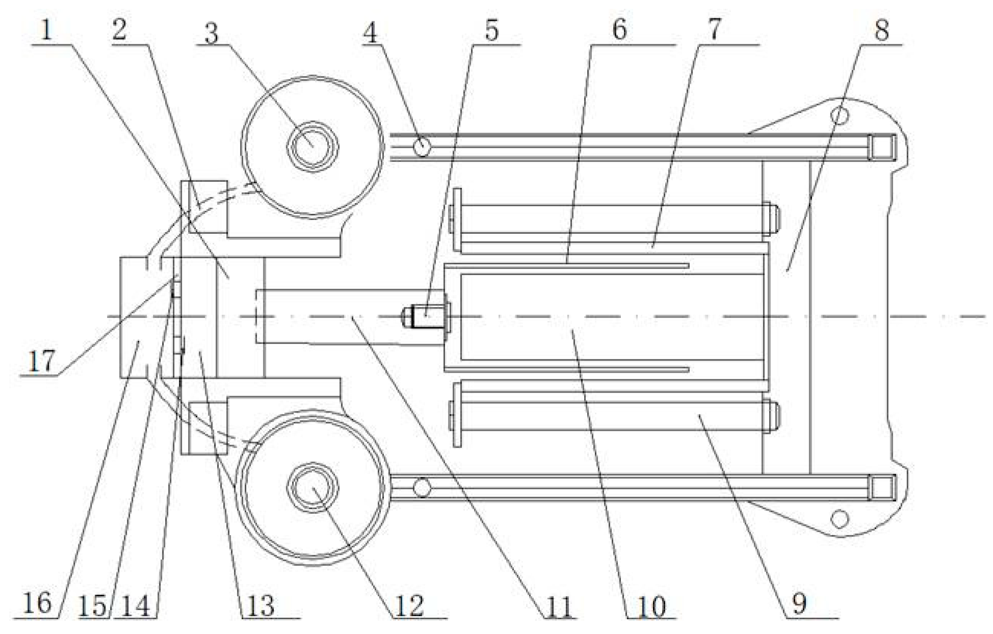
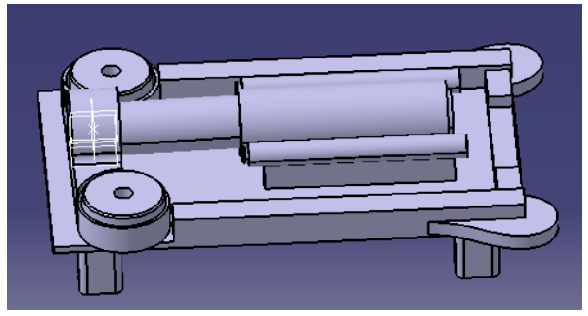
A moving-coil linear compressor is mainly composed of a power unit (moving-coil linear motor), an engine body, a connecting rod, cylinder block parts, piston parts, intake and exhaust pipelines, bolt screw holes, and other accessories, as shown in Figure 1. The power unit mainly includes the motor and related support parts. The main power source of the linear compressor is the internal moving-coil linear motor, which directly drives the piston to reciprocate in the cylinder and can maintain the stability of the direction of movement to complete subsequent cycle processes. The body mainly plays a bearing role in the structure of the linear compressor, including the two major structures of the fuselage and the base. There are various moving parts inside the fuselage that provide positioning and guiding for each transmission part. A cylinder formed by the base is installed on the base, and the linear motor is fixed to the base by fasteners [12].
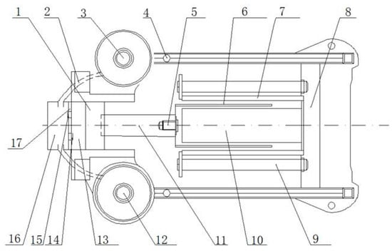
Figure 1.
Structure diagram of a moving-coil linear compressor: 1. piston; 2. air pipe; 3. exhaust port; 4. open hole; 5. screw; 6. promoter; 7. permanent magnet; 8. boss; 9. Fixing bolt; 10. iron core; 11. connecting rod; 12. air inlet; 13. cylinder; 14. intake valve; 15. exhaust valve; 16. intake and exhaust chamber; and 17. cylinder head.
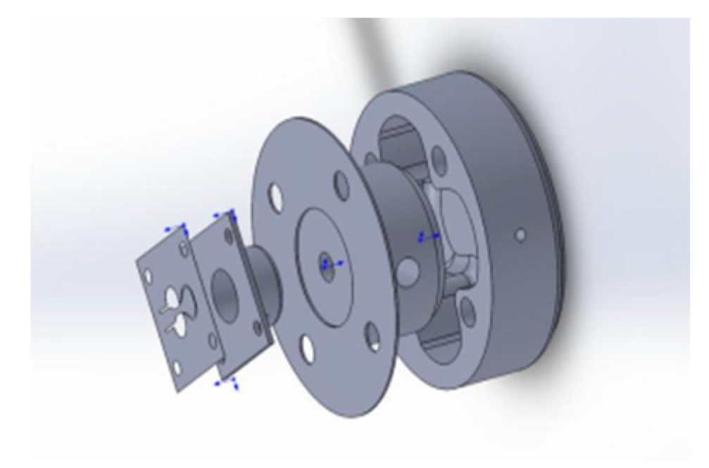
In a linear compressor, the cylinder block is an important structure for compressing refrigerants. The main components include the cylinder block, the cylinder head, etc. The cylinder parts have a more complex structure than other parts because they bear a heavy air pressure. The cylinder is provided with an intake and exhaust chamber at one end, with an air inlet and exhaust port arranged on both sides of the cylinder. The two are connected to the intake and exhaust chamber through the ventilation pipe, and a piston is placed in between. The piston parts mainly include the piston, the piston ring, etc. The piston is connected to the piston rod, the other end of which is connected with the promoter of the linear motor by fasteners. A 3D model is shown in Figure 2 [13].
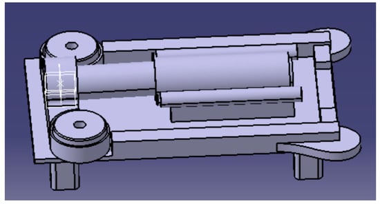
Figure 2.
Three-dimensional model of the moving-coil linear compressor.
3. Modeling of Direct-Drive Compressor with Electromagnetic Linear Actuator
In the design of a moving-coil linear motor, the priority should be size design and material selection according to its intended use. The next stage is the stator and promoter structure design, magnetic circuit analysis, and coil structure design. Finally, the structure and function of the moving-coil linear motor should be determined as a whole to achieve the best results through parameter adjustment and structure optimization.
3.1. Mathematical Model of the Moving-Coil Linear Motor
The running equation of a linear motor is composed of a balance among the circuit system, the magnetic field system, and the mechanical system [14].
The circuit system converts voltage in the moving coil into current, which can be equivalent to a resistor and an inductor in series, and the moving coil moves in a magnetic field, generating a back EMF. The coil voltage balance equation [15] is as follows:
The counter electromotive force can be expressed as follows:
where is the supply voltage; is the coil current; is the coil resistance; is the coil inductance; is the counter electromotive force during moving coil motion in the magnetic field; is the counter electromotive force constant; is the promoter motion velocity; is the magnetic flux density; and is the turns per coil.
The magnetic field system enables the linear motion of the promoter through the electromagnetic force generated in the interaction between the circuit system and the magnetic field. According to the Lorentz force on the energized coil in the magnetic field, the electromagnetic force balance equation is as follows:
where is the structural coefficient; Bis the magnetic flux density of the coil; is the effective length of each coil in the magnetic field; and is the driving force constant of the linear motor.
During operation, the moving-coil linear motor needs to overcome friction force and inertia force in motion. In addition, there is a load force; thus, the mechanical balance equation [15] is as follows:
where is the electromagnetic force; is the mass of the coil assembly; is the promoter displacement; is the damping force coefficient of the moving component in the magnetic field; and is the load force.
3.2. Parameter Design and Material Selection of the Moving-Coil Linear Motor
In the design of a moving-coil linear motor used in a direct-drive compressor with an electromagnetic linear actuator, there are the following requirements:
- (1)
- The driving force and the working stroke of the linear motor should be increased within the limited installation range;
- (2)
- The thrust performance of the linear motor should be increased to reduce fluctuation during motor operation;
- (3)
- The electromagnetic density and the magnetic circuit should be properly designed to reduce temperature rise during motor operation;
- (4)
- The mechanical efficiency and energy utilization efficiency of the motor should be increased to reduce the working energy consumption as much as possible;
- (5)
- It is necessary to meet the requirements of small size, compact structure, reliable operation, and high space utilization rate.
Therefore, the basic parameters and sizes of the moving-coil linear motor are designed as shown in Table 1 and Table 2 below:

Table 1.
Basic parameters of a moving-coil linear motor.
Table 2.
Basic size of a moving-coil linear motor.
3.3. Mathematical Model of the Moving-Coil Linear Compressor
The mechanical motion system of a moving-coil linear compressor is dominated by the reciprocating motion of the promoter, so it can be simplified to a model of a forced damping vibration system with a single degree of freedom and a single mass [16]. For a sample machine of the moving-coil linear compressor, the specific parameters are shown in Table 3. By studying the principle of the linear compressor, it is possible to simplify the mechanical subsystem into a damping vibration system with a single degree of freedom if thermodynamics factors are ignored.
Table 3.
Basic parameters of the linear compressor.
The mechanical subsystem of the moving-coil linear compressor is dominated by the reciprocating linear motion of the promoter of the linear motor, which is now simplified as forced damped vibration with a single degree of freedom and a single mass. The promoter is taken as the research object, which is subjected to an electromagnetic force , a gas load force , a friction force , a spring force , an inertia force, and a damping force. These forces form the force balance equation of the mechanical subsystem of the moving-coil linear compressor. According to the mechanical subsystem model of the permanent-magnet moving-coil linear compressor, its force balance equation can be obtained as follows [17]:
where m is the promoter mass; x(t) is the promoter motion displacement; t is the working time; is the static equilibrium position of the promoter; K is the spring stiffness coefficient; c is the damping coefficient of the mechanical subsystem; is the electromagnetic driving force; and is the gas load force.
The gas load force is the force acting on the piston under the pressure difference between the interior and exterior of the cylinder, which size is proportional to the area and the pressure difference of the piston:
where A is the cross-sectional area of the piston; is the gas pressure in the cylinder; and is the exhaust back pressure outside the cylinder, which is the atmospheric pressure under normal situations.
In the calculation of the electromagnetic force generated by the driving linear motor, the turns per coil N, the air-gap magnetic induction intensity B, and the effective length l of the single-turn coil are all constant values; only current i is a variable. Thus, the electromagnetic driving force can be expressed as follows:
Because of the constant reciprocating motion of the piston in the cylinder, the gas pressure in the cylinder changes constantly. A reciprocating linear motion of the piston involves four processes: intake, compression, exhaust, and expansion. The gas pressure in the cylinder can be expressed using a piecewise function [18]:
where is the intake pressure of the air inlet, which is the atmospheric pressure under normal circumstances; is the exhaust pressure of the exhaust port; S is the stroke of the linear compressor piston; is the distance from the piston apex to the valve assembly at the end of the exhaust process, i.e., the clearance; and n is the polytropic exponent.
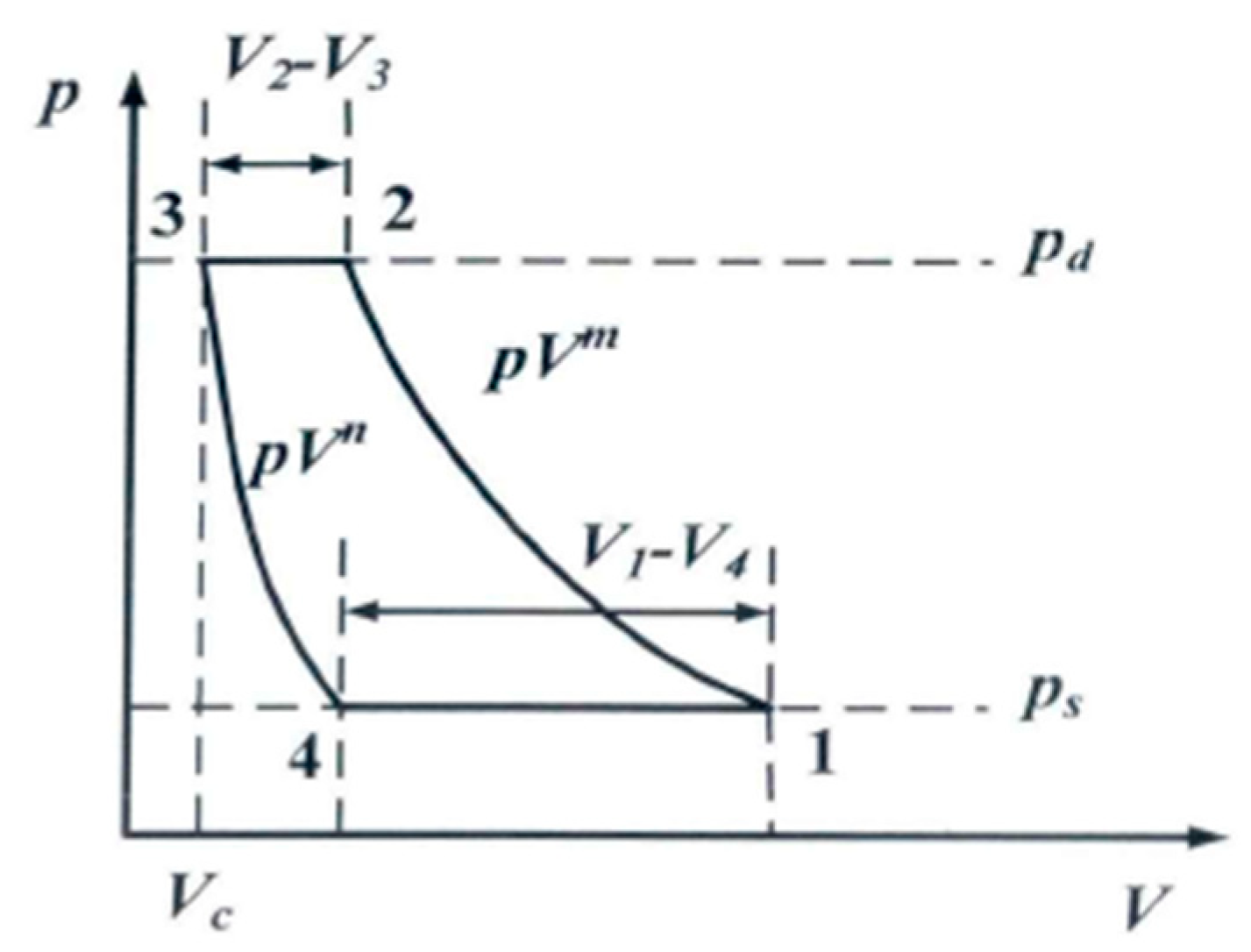
The movement pressure diagram of the compressor [19] is shown in Figure 3. The figure shows the following: one to two is the compression process; two to three is the exhaust process; three to four is the expansion process; and four to one is the intake process.
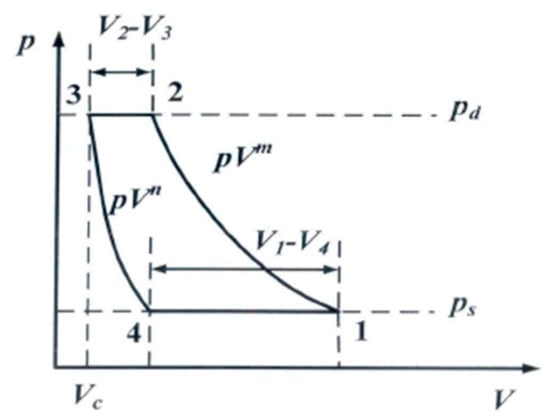
Figure 3.
Compressor pressure diagram.
Due to the use of suction and exhaust valves to control the flow of working fluids, a linear compressor for refrigeration has an ideal working process, as shown in Figure 3, and the process is a nonlinear process.
Due to the existence of gap volume, the gas in the cylinder will exchange heat with the wall in contact during the expansion process; thus, the expansion process is not a straight line as shown by the theoretical cycle, but a curve, as shown in Figure 3.
During the actual operation, because of the influence of the spring force, flow resistance, heat exchange, etc., of the gas valve, the suction and exhaust valve is delayed in opening, and the pressure and temperature of the actual suction and exhaust process change, which is not according to the linear process shown by the theoretical cycle, but a curve process with fluctuations that slightly convex up and down; however, its fluctuations and changes are small, and it is still regarded as the linear process shown by the theoretical cycle when analyzed.
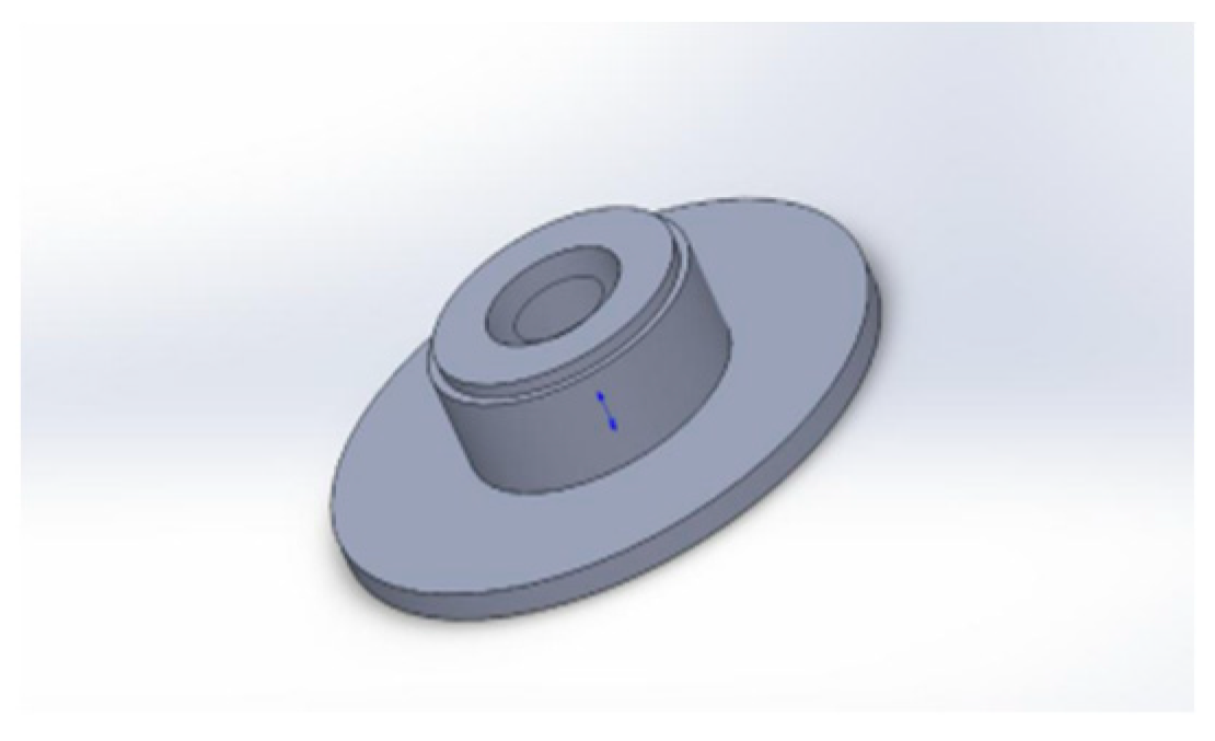
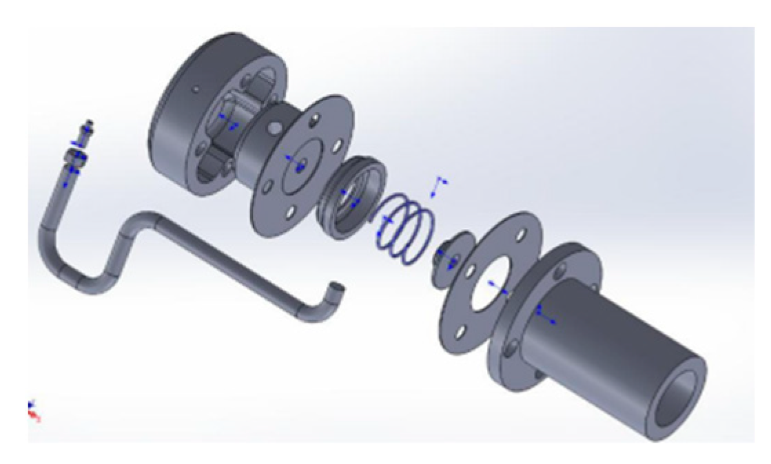
The intake and exhaust valves are based on the LG compressor which model is LA95LAEM. The exhaust mechanism collects compressed gas in the cylinder to reduce exhaust noise and introduce the gas to the next place of use, as shown in Figure 4 and Figure 5.
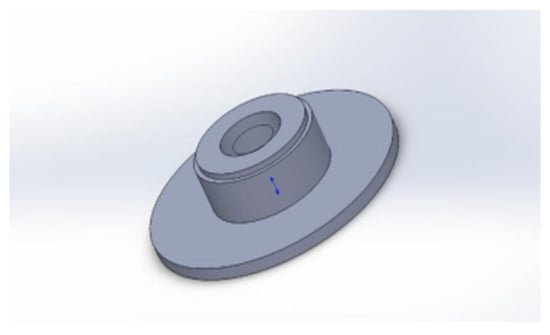
Figure 4.
Vent valve disc and seat.
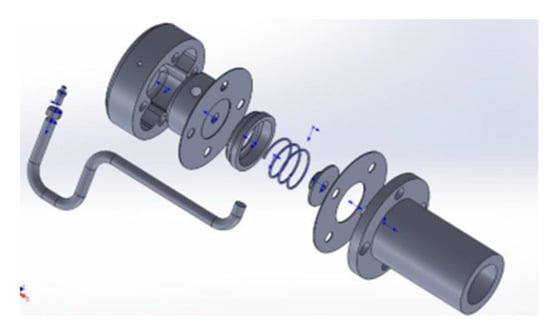
Figure 5.
Connection diagram of each exhaust part.
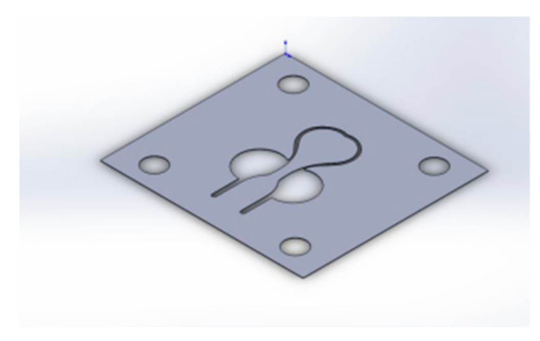
The intake mechanism can suck low-pressure gas into the body, which is screened by the intake valve and then fed into the working chamber to compress air in the piston to complete the compression of the gas. This is shown in Figure 6 and Figure 7.
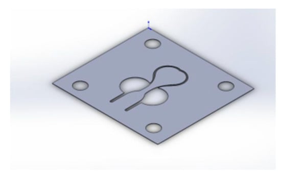
Figure 6.
Inlet valve plate.
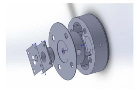
Figure 7.
Connection diagram of each component of the intake valve.
R134a is selected as the compressor refrigerant. According to the pressure enthalpy diagram, the exhaust pressure is 1.016 MPa and the intake pressure is 0.08437 MPa. The dividing points of the linear compressor during the compression, exhaust, expansion, and intake processes are obtained from Equation (8).
According to the equivalent circuit diagram of the electromagnetic subsystem of the moving-coil linear compressor, the voltage balance equation can be obtained as follows [20]:
where is the effective resistance of the moving coil; i is the current in the moving coil; is the magnetic field intensity in the air gap; is the effective total length of the moving coil; L is the self-inductance coefficient of the moving coil; and U(t) is the voltage at both ends of the moving coil.
The linear motor efficiency of the permanent-magnet moving-coil linear compressor can be expressed as follows:
where is the linear motor efficiency of the permanent-magnet moving-coil linear compressor; is external work performed by the permanent-magnet moving-coil linear compressor; and is the input energy of the permanent-magnet moving-coil linear compressor.
4. Results
4.1. Simulation Analysis of the Moving-Coil Linear Motor under Maxwell
For an axially symmetric moving-coil linear motor, only half of the two-dimensional motor model needs to be built, as shown in Figure 8. The two-dimensional model of the moving-coil linear motor mainly consists of an inner magnetic yoke, an outer magnetic yoke, a bottom plate, a coil, a coil former and a permanent magnet, among other components. Hence, after the establishment of the two-dimensional model for the motor, material selection and distribution is carried out for the above parts, with the materials of each part shown in Table 4 [21].
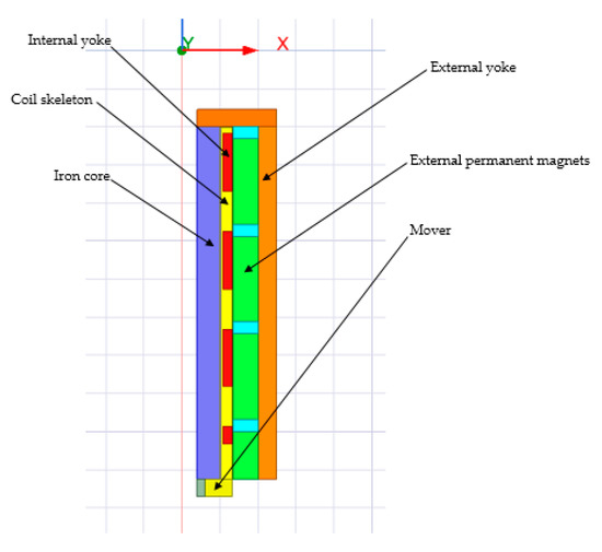
Figure 8.
Two-dimensional model of the moving-coil linear motor under Maxwell.
Table 4.
Materials for each part of the moving-coil linear motor.
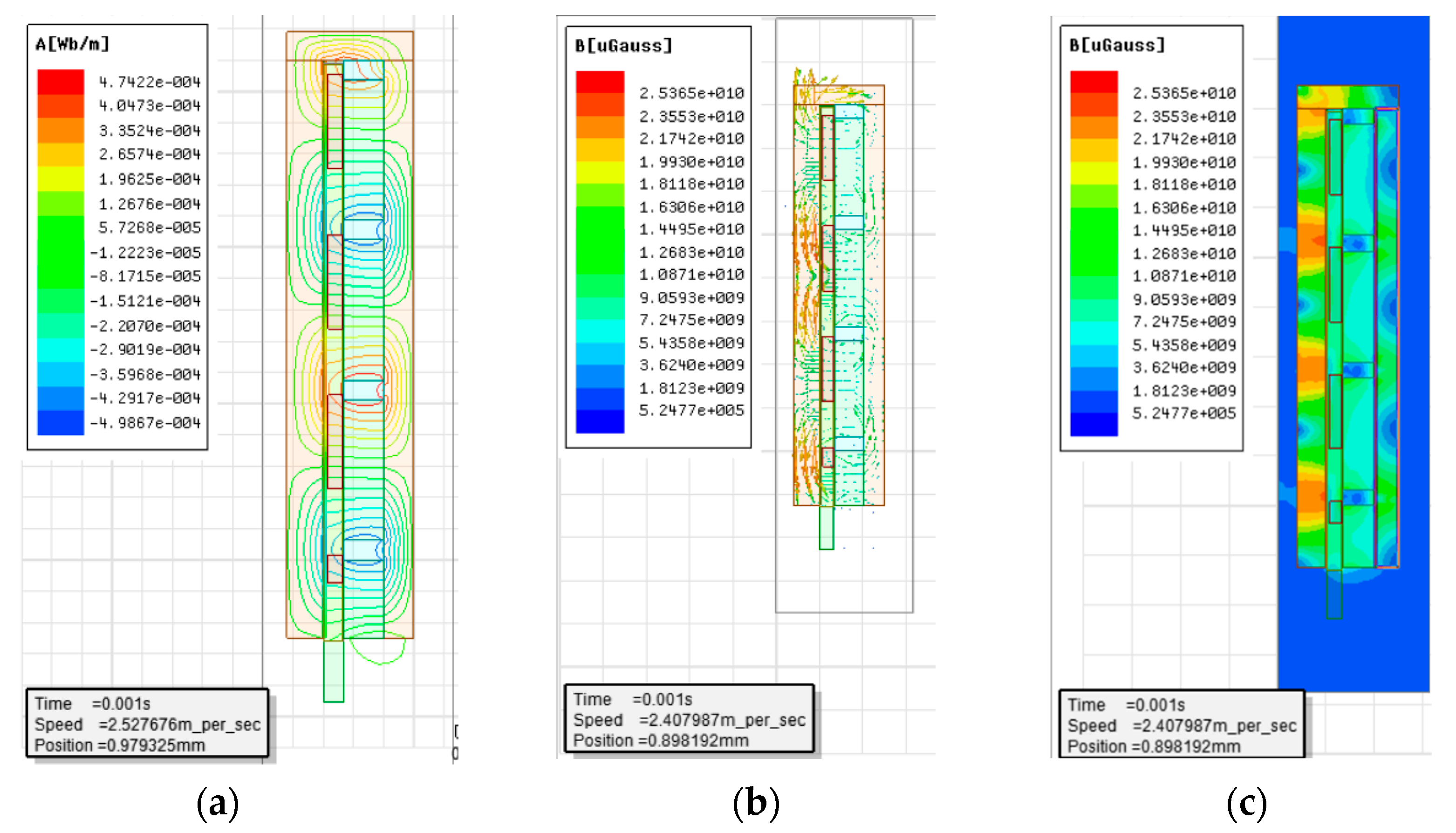
For axisymmetric moving-coil linear motors, only half of the 2D motor model needs to be created. Using the Maxwell 2D module, the coordinates are established so that the Z-axis is the axis of rotational symmetry, and a model is created, as shown in Figure 9, according to the specified motor parameters. Among them, Figure 9a–c show the magnetic contour distribution diagram, the magnetic vector distribution diagram, and the magnetic flux distribution diagram of the linear motor.
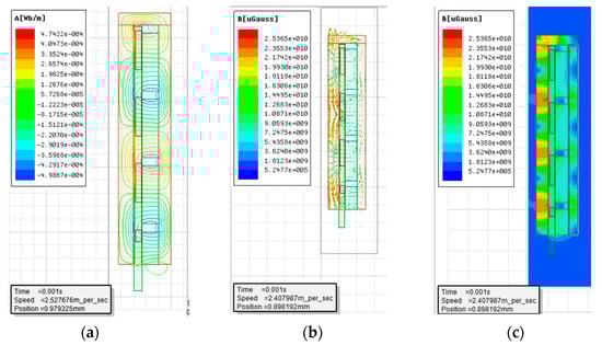
Figure 9.
Magnetic distribution diagram of the linear motor. (a) Magnetic contour distribution diagram of the linear motor; (b) Magnetic vector distribution diagram of the linear motor; (c) Magnetic flux distribution diagram of the linear motor.
According to the simulation results, the maximum magnetic field line is 4.7422 × 10⁻⁴ Wb/m, and the maximum magnetic induction intensity is about 2.25 T. According to Gauss’s law, each magnetic field line is closed, and the size of the magnetic field line gradually decreases from the inside to the outside due to the mutual repulsion of the magnetic field lines, resulting in each magnetic field line being independent and not intersecting with other magnetic field lines.
Through simulation, it is possible to know the thrust fluctuation, the promoter motion velocity variation, and the promoter position change of the moving-coil linear motor, with the specific simulation results shown in Figure 10, Figure 11 and Figure 12.
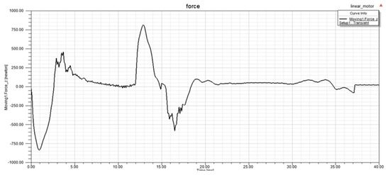
Figure 10.
Positioning thrust fluctuation diagram of the moving-coil linear motor.
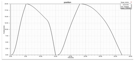
Figure 11.
Linear motion position diagram of the moving-coil linear motor.
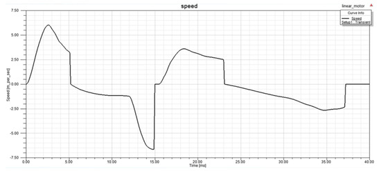
Figure 12.
Velocity fluctuation diagram of the moving-coil linear motor.
When the linear motor begins operation, its thrust is negative and increases rapidly. With the passage of time, the thrust gradually decreases, with the direction turning from negative to positive. At about 13 ms, the thrust reaches the maximum value of about 800 N, which satisfies the expected design requirements. The thrust then gradually decreases and hovers around 0 N.
The designed moving-coil linear motor has a maximum stroke of 20 mm. According to the variation curve of its motion position with time, the promoter of the moving-coil linear motor completes two reciprocating motions within 40 ms, reaching the maximum stroke of 20 mm at about 5 ms and 23 ms, respectively.
At the beginning, the promoter velocity first increases and then decreases. When the maximum motion stroke is reached, that is, after about 5 ms, the velocity is 0. Then, the promoter motion velocity increases in the opposite direction. In the meantime, the promoter performs a counter motion and returns to its origin with a velocity of 0 at about 15 ms. Afterward, the motion velocity increases in the positive direction. When the maximum stroke is reached again, the velocity slows to 0 at about 23 s. Then, it accelerates in the reverse direction, and the promoter returns in the opposite direction, with its velocity decreases to zero at the end of the motion.
The above simulation results show that, when the linear motor starts operation, the thrust increases in a reverse direction under the system interference, and both the velocity and motion stroke of the moving coil are 0 mm. Over time, the thrust changes from negative to positive, and the motion velocity of the moving coil also increases, with the motion stroke curve presenting an upward trend. When the maximum stroke is nearly reached, the linear motor current provided by the system decreases, with the motion velocity and thrust of the moving coil also decreasing. The velocity slows to 0 m/s when the moving coil stroke is 20 mm. During the return of the moving coil, the velocity increases in the reverse direction, and the thrust decreases slowly with the decrease in the stroke until it reaches 0 mm. At about 15 ms, the moving coil restores the initial state in terms of thrust, velocity, and stroke.
4.2. Dynamic Simulation and Analysis of the Moving-Coil Linear Compressor under Simulink
4.2.1. Dynamic Modeling Simulation
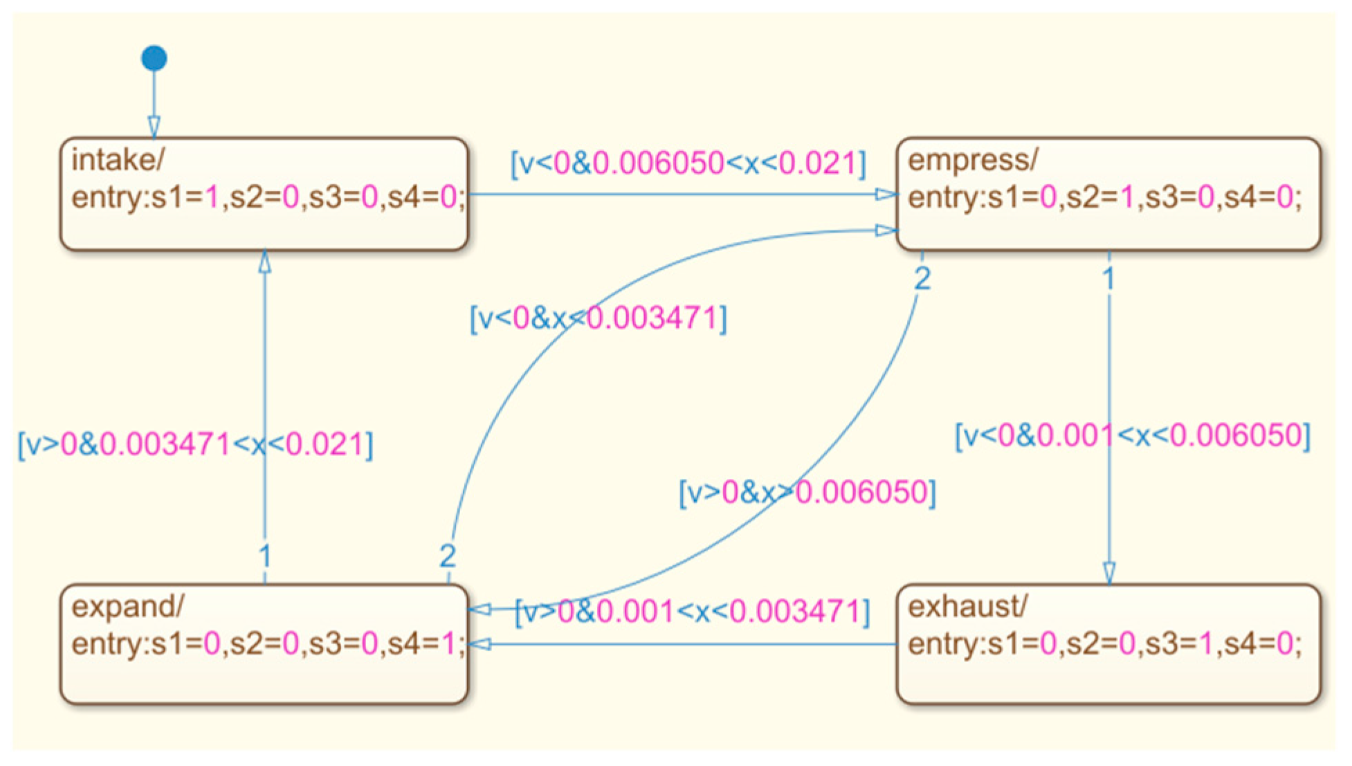
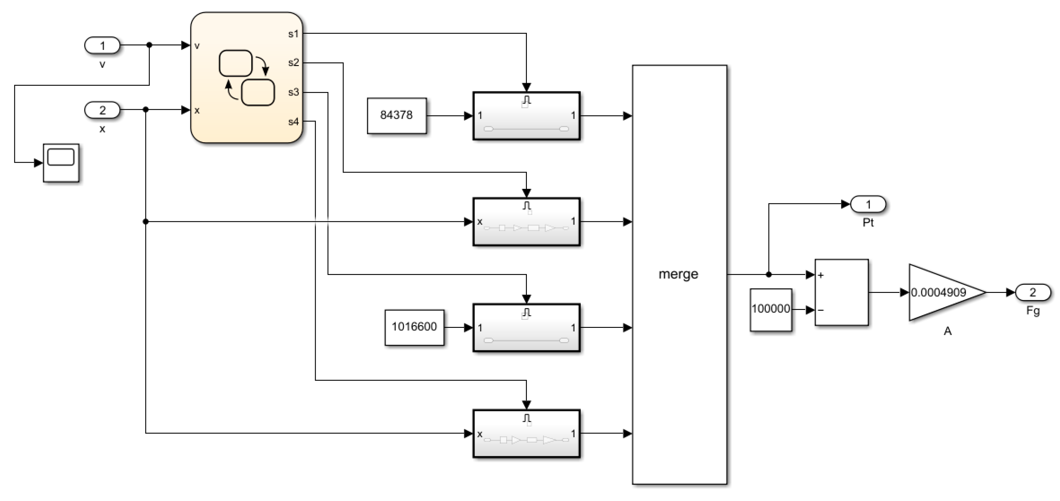
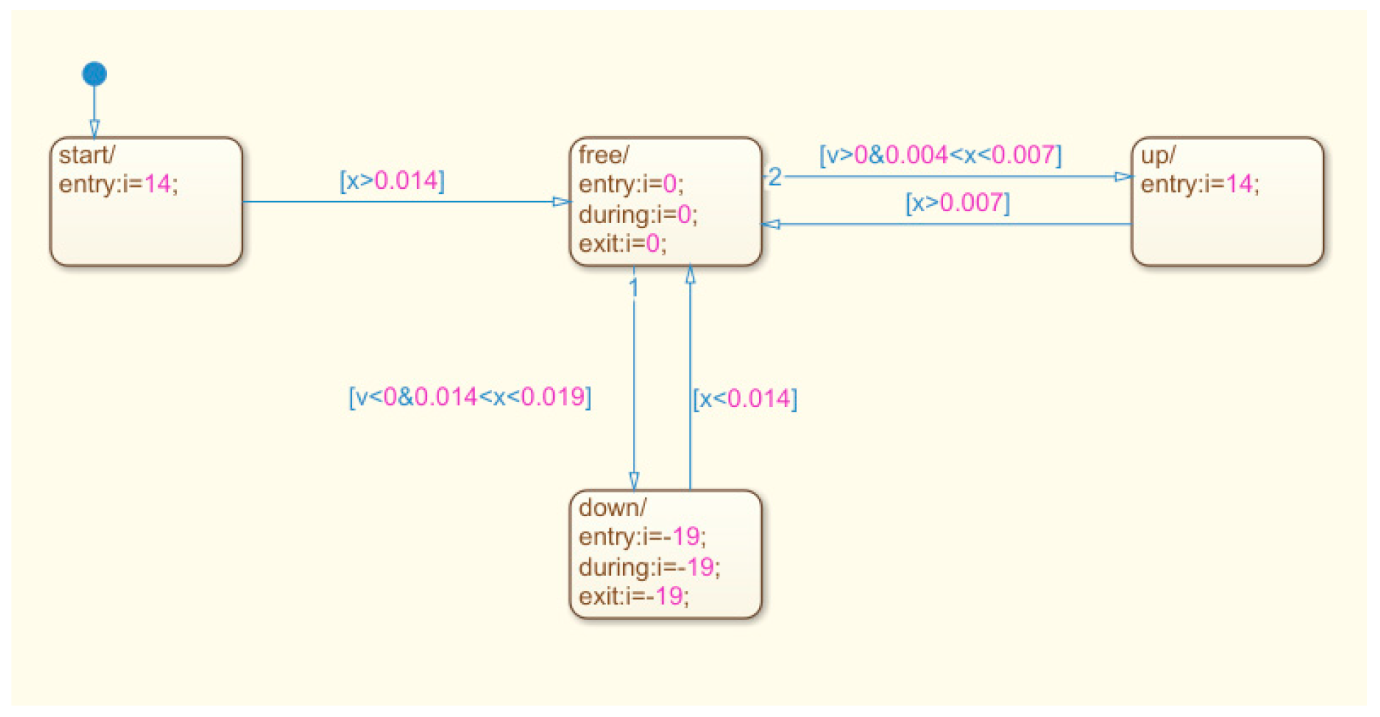
According to the working principle of the moving-coil linear compressor, a model of air pressure under the four working conditions can be established in Simulink. When the piston moves, the piston movement needs to be exchanged between the four states, and the corresponding conditions need to be set to change the state. This can be achieved with the help of the chart module in Stateflow, as shown in Figure 13. In order to bring the simulation closer to reality, special cases must be considered, including when the electromagnetic force is too small, so that the displacement does not reach 0.003471 m during expansion and the speed is already less than 0 m/s, which causes the expansion state to jump directly into the compression state. Similarly, during the compression process, when the displacement does not reach 0.006050 m, the speed is already greater than 0 m/s, causing the compression state to jump directly into the expansion state. The Simulink model of the gas load force is built; the input signals are the displacement and velocity, and the output signals are the gas load force and the gas pressure in the cylinder, as shown in Figure 14.
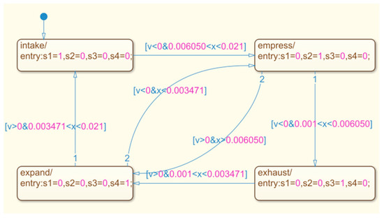
Figure 13.
Stateflow model diagram of piston movement.
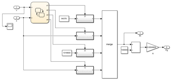
Figure 14.
Simulink model diagram of gas load force.
After the gas load force Simulink model is built, according to Equation (5), the mechanical subsystem of the Simulink model could be obtained, and the output signals of this model are the displacement x, velocity v, current I, and electromagnetic driving force , as shown in Figure 15.
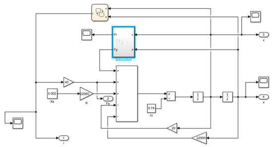
Figure 15.
Power system model diagram of the moving-coil linear compressor.
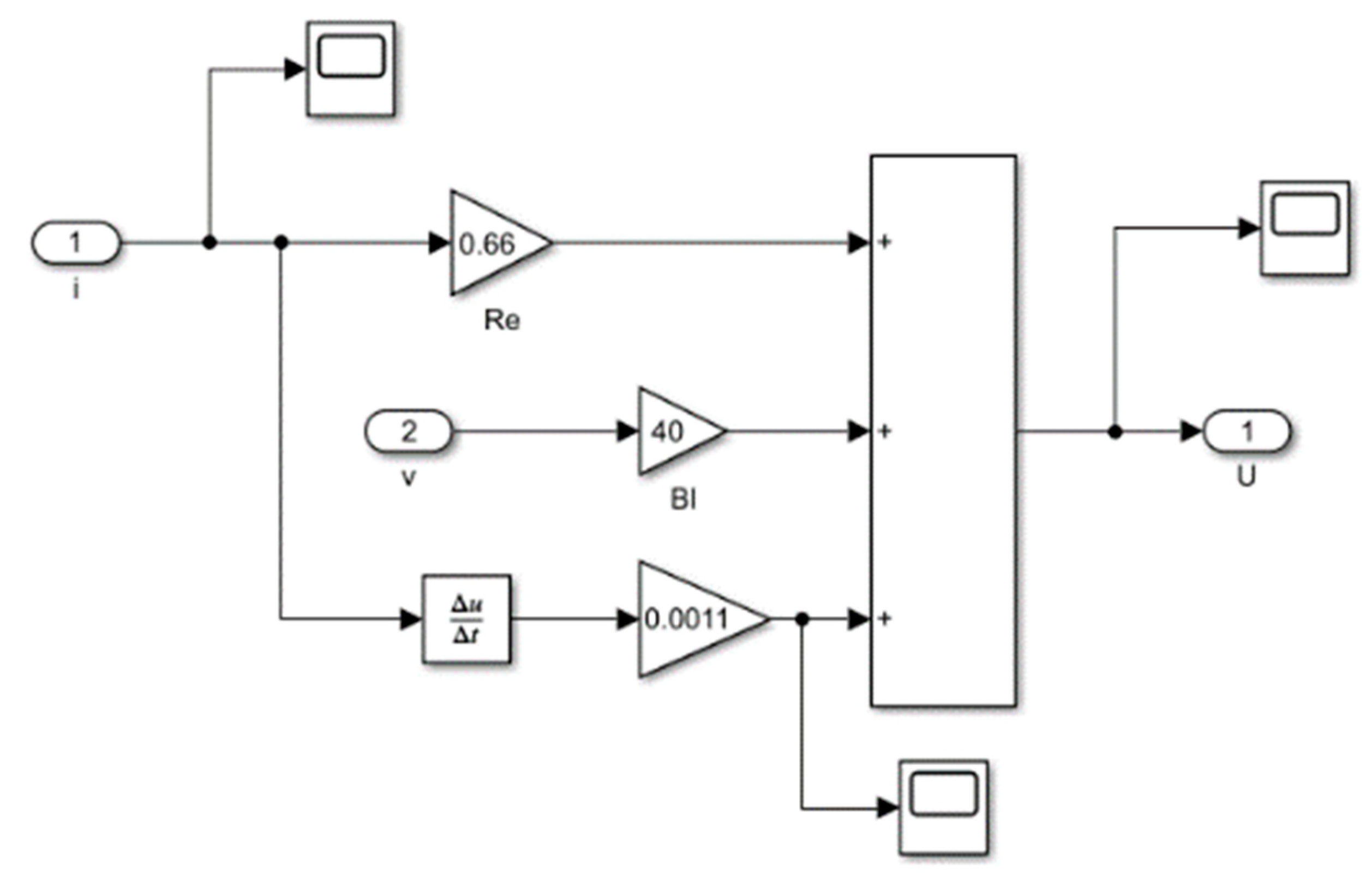
According to Equation (9), the electromagnetic subsystem of the Simulink model could be obtained. The input signals of the electromagnetic subsystem of the Simulink model are the motion speed v of the piston and the current i in the moving coil, and the output signal is the voltage U in the moving coil, as shown in Figure 16.
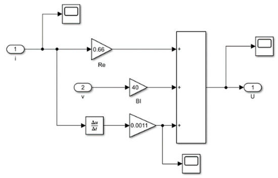
Figure 16.
Model diagram of electromagnetic subsystem.
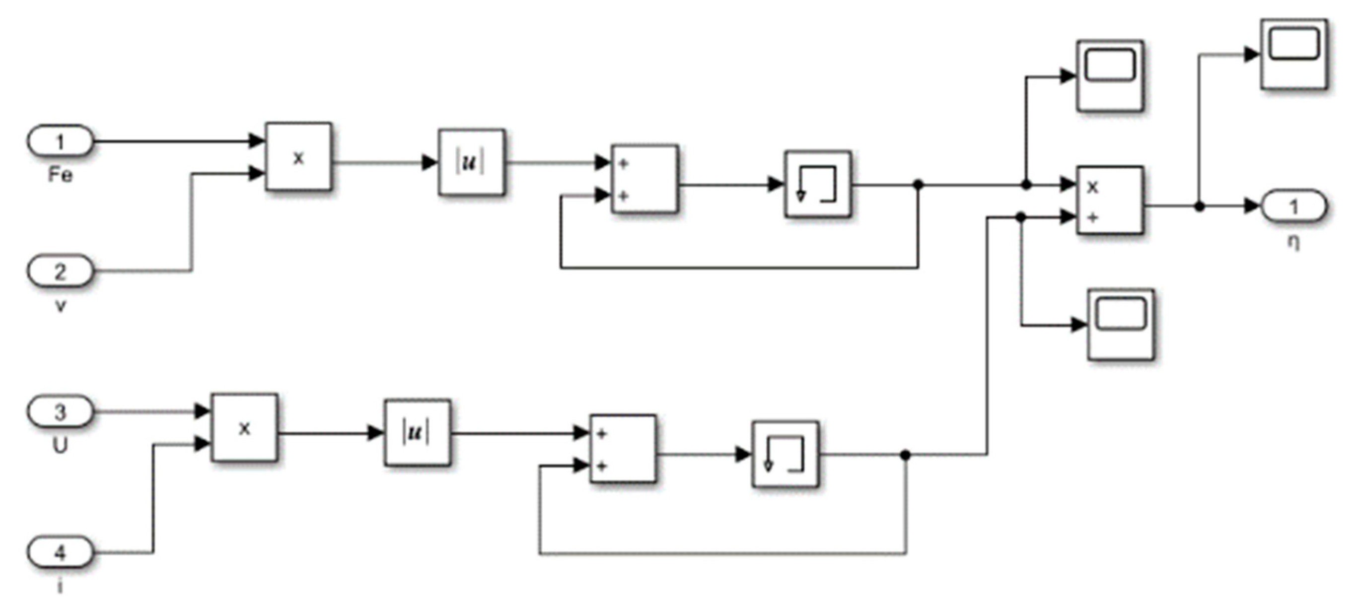
According to Equation (10), the calculation model of the efficiency of the direct-drive compressor [22] with an electromagnetic actuator in Simulink could be obtained, as shown in Figure 17. The input signals of this model are the electromagnetic driving force, the speed v of the moving coil, the voltage U across the moving coil, and the current i in the moving coil. The output signal is the efficiency of the permanent-magnet moving-coil linear compressor. As can be seen from Figure 18, the Simulink model for this efficiency continuously accumulates the instantaneous power value of the permanent-magnet moving-coil linear compressor and the instantaneous power value of the energy of the permanent-magnet moving-coil linear compressor’s external input, and divides the two; then, the efficiency of the permanent-magnet moving coil linear compressor is obtained. With an increase in simulation time, the efficiency value tends to a stable value, which is the efficiency value of the linear motion of the permanent-magnet moving-coil linear compressor.
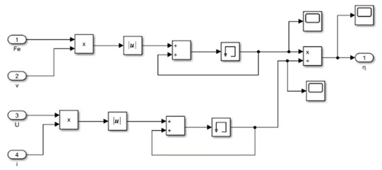
Figure 17.
Efficiency calculation module’s model diagram.
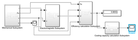
Figure 18.
Simulink model diagram of the linear compressor.
The dynamic linear compressor in the Simulink model is composed of the mechanical subsystem, electromagnetic subsystem, and compressor cooling capacity calculation module. The refrigeration capacity is the product of the unit refrigeration capacity and the mass flow; the refrigeration capacity is linearly related to the mass flow, as the refrigeration capacity is proportional to the mass flow. Therefore, a linear function module is established, and the refrigeration capacity of the linear compressor [23] could be obtained. The Simulink model of the moving-coil linear compressor is shown in Figure 18. The efficiency of the linear motor currently reaches more than 80%, and there is still room for improvement in the motor efficiency after further control.
4.2.2. Dynamic Simulation Analysis
According to the above Simulink linear compressor model, the simulation results obtained using the trial method are as follows:
The push-to-push control strategy [24] is used to set the magnitude of the current in the coil. By feeding periodic DC power to the armature linear compressor, the DC generates periodic electromagnetic forces in different directions and is accompanied by damping forces. It has been calculated that the linear motor compressor requires at least a 450 N electromagnetic driving force. The working process of the direct-drive compressor with an electromagnetic actuator is shown in Figure 19.
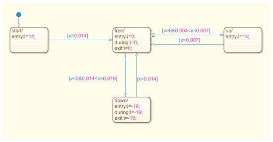
Figure 19.
Signal input diagram of electromagnetic force current.
When the direct-drive compressor with an electromagnetic actuator is energized and starts working, the moving coil is first given a positive excitation current of 14 A. When the piston moves from the initial displacement of 11 mm to the displacement of 15 mm, the current in the moving coil becomes zero. Then, the piston moves under the action of inertia to a displacement of 20 mm. The piston then begins to move in a negative direction into the compression process. When the piston moves to a displacement of 19 mm, the current in the moving coil becomes −19 A until the piston moves to a displacement of 14 mm. When the current in the moving coil becomes zero, then the piston moves under the action of inertia to a displacement of 6.050 mm, and the compression process ends. The piston then enters the exhaust process under the action of inertia until it moves to a displacement of 1 mm, at which point the velocity is zero and the exhaust process ends. Under the action of the spring, the piston begins to move in a positive direction into the expansion process. When the piston moves to a displacement of 4 mm, the current becomes 14 A, and when the piston moves to 3.471 mm, the expansion process ends. Then, the piston still moves positively under the action of the electromagnetic force and enters the suction process; when the piston moves to a displacement of 7 mm, the current becomes zero. Then, the piston moves to 21 mm under the action of inertia. At this point, the speed is zero and the intake process ends. Then, the piston moves in a negative direction to enter the compression process, and the cycle begins again.
Using the trial method, each group of current is simulated in the whole system to obtain the appropriate current parameters, that is, this set of current data allows the linear compressor to work continuously to prove the feasibility of the compressor’s control strategy accordingly. The data obtained by the trial method can be input into the system, and the simulation results of the direct-drive compressor with an electromagnetic actuator can be obtained, as shown in Figure 20, Figure 21 and Figure 22.
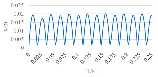
Figure 20.
Dynamic linear compressor displacement simulation waveform.
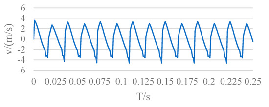
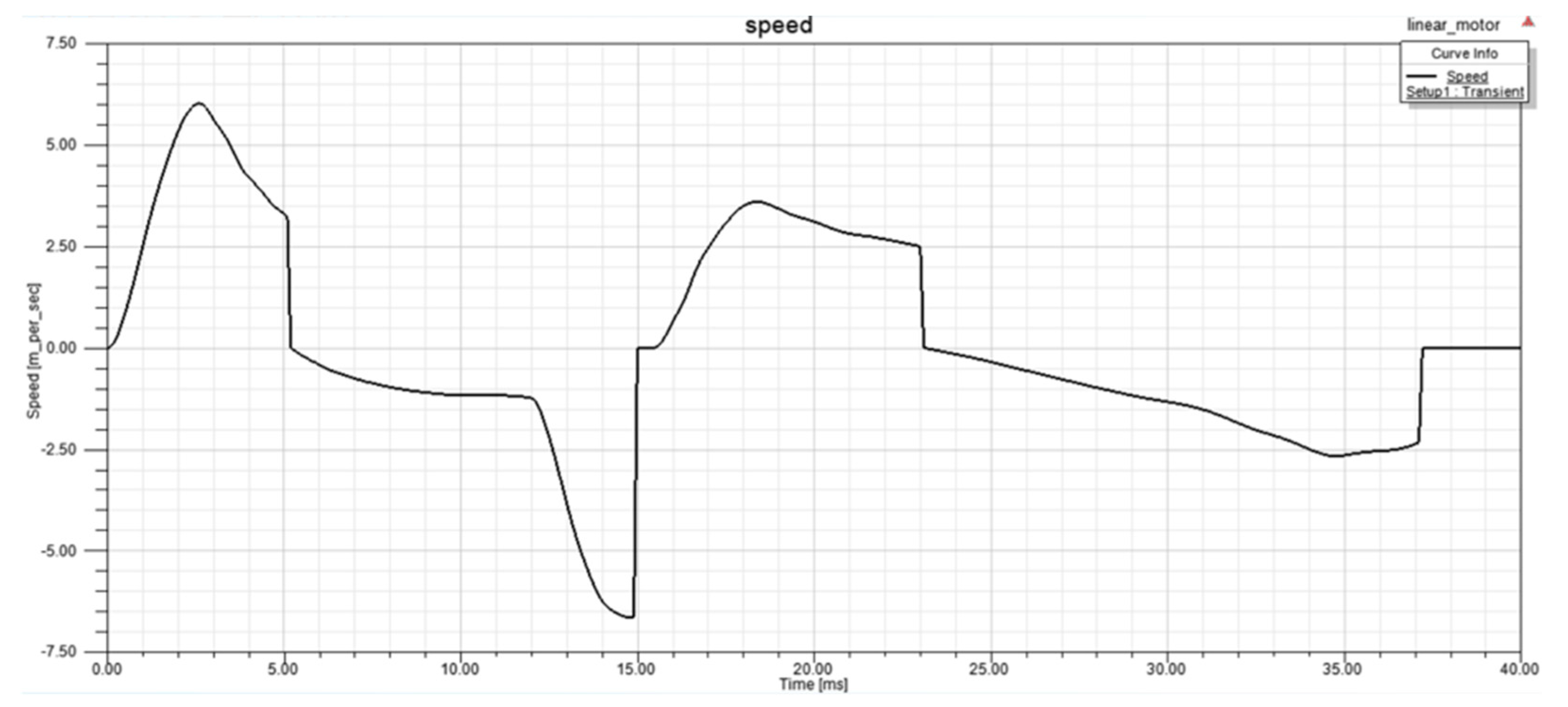
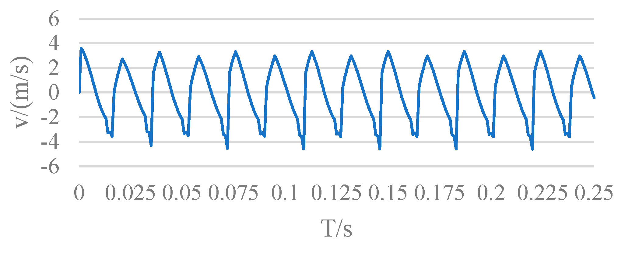
Figure 21.
Dynamic coil linear compressor speed waveform diagram.
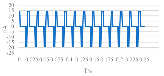
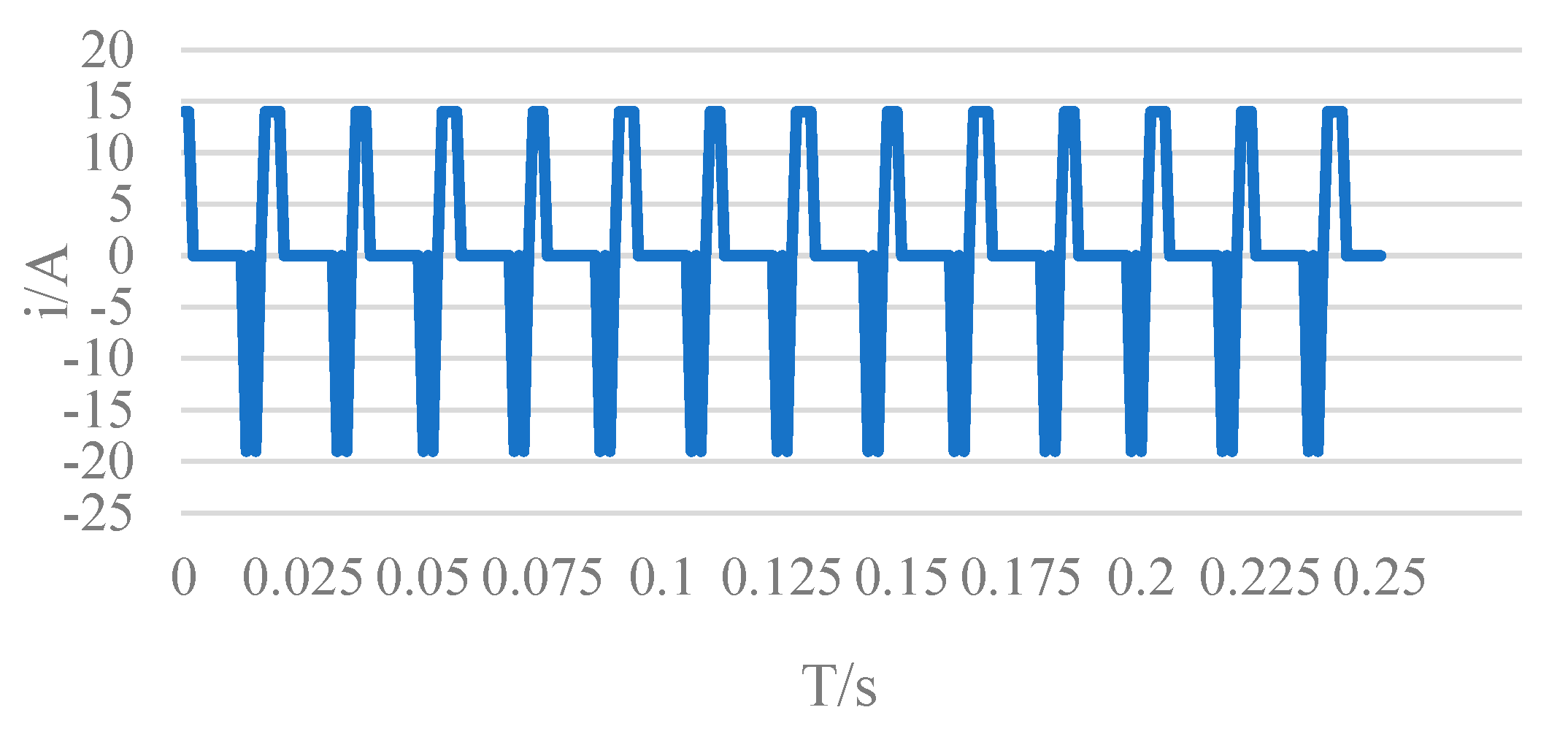
Figure 22.
Current waveform diagram.
The piston carries out periodic movement in the cylinder. The amplitude of the piston is kept at about 20 mm, and there is a slight fluctuation, with a maximum amplitude between [−0.01, 0.020]. This error is within the allowable range. The result is fully in line with the working requirements of the moving-coil linear compressor.
From the waveform diagram of the motion speed of the linear compressor piston, it can be seen that the simulation results of speed are kept within the [−6, 6] range, the movement speed of the piston is kept within the allowable maximum speed of the compressor, and the movement speed is reasonable and meets the working requirements of the compressor.
The coil current is the input signal, and it can be seen from Figure 16 that the change law of the input coil current setting is specified when setting the model. Due to the unstable working state of the compressor at start-up, the input of the coil current fluctuates slightly, but as the compressor operates, the working state gradually stabilizes, and the coil current remains periodically changing between −19 A and 14 A. The electromagnetic force drives the compressor to work normally, and the current flow meets the basic requirements of the compressor.
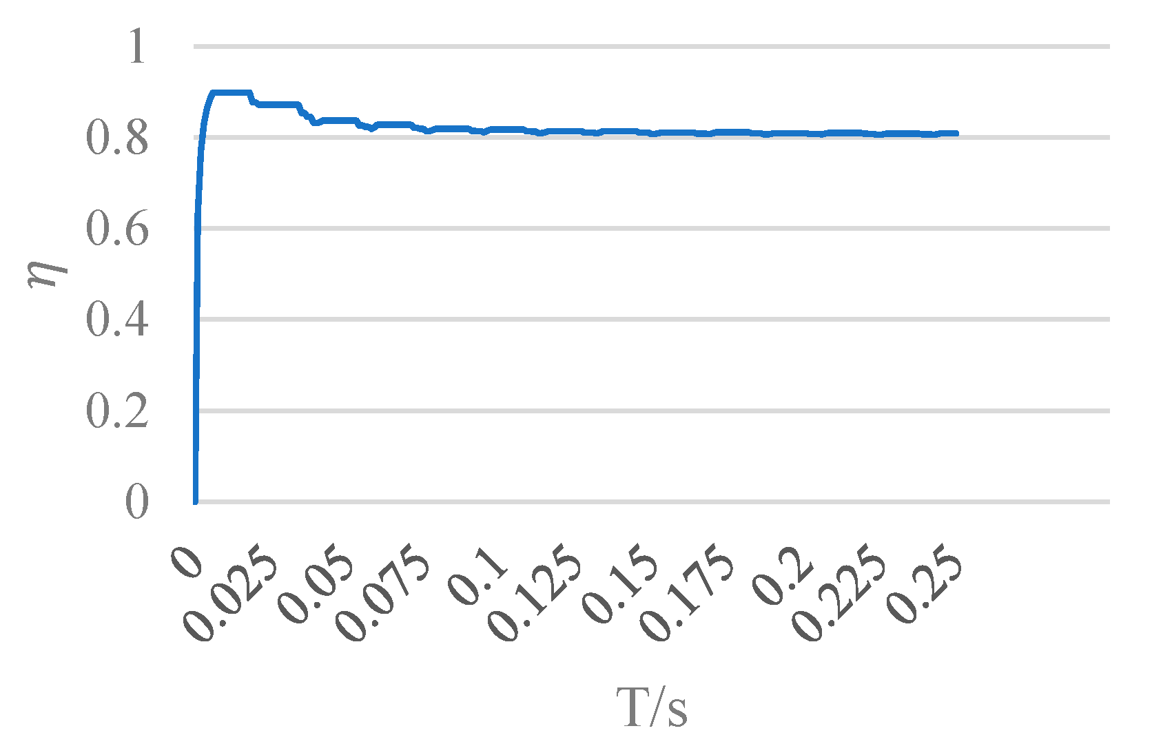
According to the efficiency calculation principle of the linear compressor motor and Equation (10), from the output waveform diagram, it can be seen that the efficiency value increases rapidly, until it reaches 80.93%, and slowly becomes stable, which is in line with the basic requirements of compressor work, as shown in Figure 23.

Figure 23.
Linear motor efficiency waveform diagram.
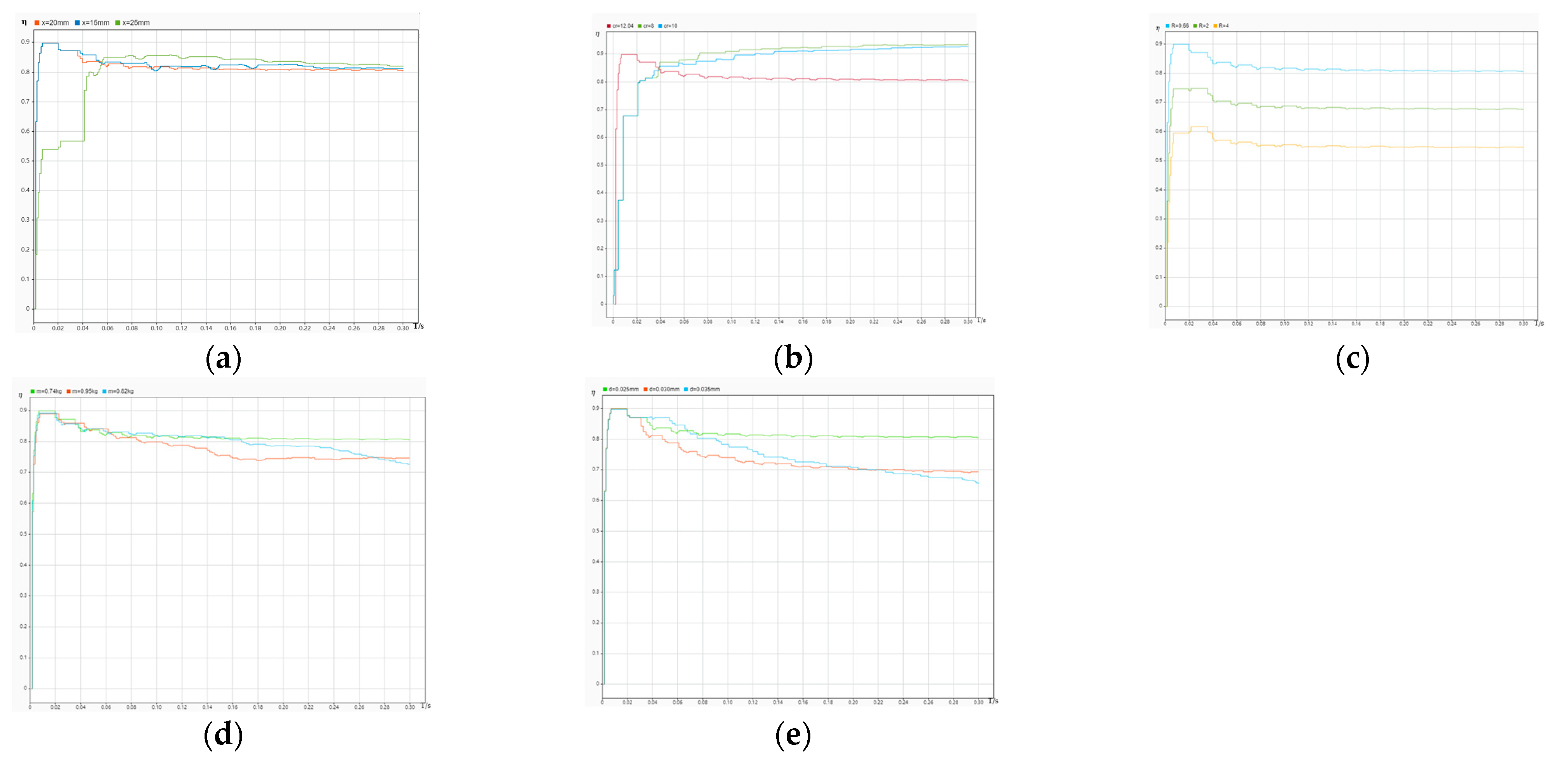
In the figures below, Figure 24a–e shows the simulation results of the compressor motor efficiency under different strokes, different compression ratios, different coil resistance and damping, different mover masses, and different piston diameters, respectively.
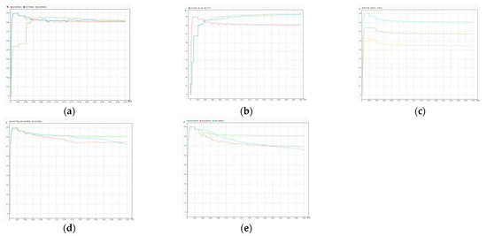
Figure 24.
Efficiency under different conditions. (a) The efficiency of the compressor at different strokes; (b) The efficiency of the compressor at different compression ratios; (c) The efficiency of the compressor under different resistance and damping; (d) The efficiency of the compressor under different mover masses; (e) The efficiency of the compressor at different piston diameters.
By changing the piston stroke, for example, we set the piston stroke to 15 mm and 25 mm, we can see that the stroke has almost no effect on the efficiency of the motor. In subsequent work, we will control the model more accurately through a control algorithm to observe the factors influencing efficiency more clearly. Three sets of displacements are listed, which are 15 mm, 20 mm, and 25 mm, and the efficiency comparison chart is shown in Figure 24a.
It can be seen from Figure 24b that with an increase in the compression ratio, the compressor efficiency gradually increases, and the compression ratio has a greater impact on the compressor efficiency. However, it is not the case that larger compression ratio is better; the choice of compression ratio should be considered comprehensively in order to reduce energy consumption as much as possible, and the compression ratio should not be too large.
As shown in Figure 24c, the simulation curve of compressor efficiency under different coil resistances is comparable, and the influences of resistance and damping on efficiency are comparable. It can be seen from the figure that as the coil resistance increases, the compressor efficiency decreases. This is because the coil resistance directly affects the size of the driving current, which in turn affects the supply voltage, resulting in a decrease in compressor efficiency. The magnitude of the damping directly affects the acceleration of the system, thereby affecting the efficiency of the compressor. Therefore, in the design and manufacturing process of dynamic linear compressors, the damping friction between the piston and the cylinder and the coil resistance should be reduced as much as possible.
The mover mass of the linear compressor is an important factor affecting the efficiency of the compressor, as shown in the simulation curve of the compressor efficiency under different mover masses (Figure 24d). As the quality of the piston increases, the compressor becomes less and less efficient. This is because the greater the mass of the piston, the more energy the system loses and, thus, the lower the efficiency.
The piston diameter is also an important factor affecting the efficiency of the motor and the compressor, as shown in the simulation curve of the compressor efficiency under different piston diameters (Figure 24e). This is because as the piston diameter increases, the gas load force also increases, and the greater the force that the motor needs to overcome, the lower the compressor efficiency is.
5. Discussion and Conclusions
In this paper, a direct-drive compressor with an electromagnetic linear actuator is designed, and the moving-coil linear motor and linear compressor are simulated by the Maxwell software and Simulink software, respectively. This paper establishes a mathematical model for the direct-drive compressor with an electromagnetic actuator. However, there are still areas for improvement, such as the stepless adjustment of refrigeration capacity through control strategies, so that the efficiency of the compressor is further improved, so as to improve the refrigeration efficiency and reduce energy consumption. The main conclusions are as follows:
- Based on the analysis of the working principle of moving-coil linear compressors, a direct-drive compressor with an electromagnetic linear actuator was designed. Compared to a traditional compressor, this paper adopts the direct-drive mode of high-performance electromagnetic linear actuator, which simplifies the structure, has no friction, reduces energy consumption, realizes the miniaturization and intelligent needs of the compressor, and improves the compressor efficiency.
- The Maxwell and Simulink software were used to simulate the kinematics of the moving-coil linear compressor. The “push-to-push” control strategy was used to control the compressor current. The piston velocity displacement and electromagnetic force current exhibit periodic changes and meet the design requirements. Although the established design requirements are met, further experiments and improvements are needed in practical applications. This verifies the feasibility of a direct-drive compressor with a linear electromagnetic actuator.
- Through the method of multiple trials, a set of data could be obtained to make the compressor work continuously, and the efficiency of the linear motor could reach 80%. In future work, through employing a control algorithm, the efficiency of the linear motor and the cooling efficiency can be improved.
- Through simulation, the efficiency of the compressor under different strokes, different mover masses, different resistance and damping, different compression ratios and different piston diameters is obtained, which further verifies the feasibility of using electromagnetic actuators to directly drive compressors.
Author Contributions
J.Z. was responsible for modeling and simulating the compressor using the Maxwell and Matlab/Simulink software, as well as reviewing and revising the article to complete the final draft. M.X. wrote the article and completed the first draft. J.D. was responsible for analyzing and managing the simulation data and verifying the results. Z.Y. and J.Y. were responsible for the collection and collation of preliminary materials and preparations for later work. All authors have read and agreed to the published version of the manuscript.
Funding
This research was funded by the National Natural Science and Technology Foundation of China (Grant No. 51605183, 51975239); the Industry-University-Research Cooperation Project of Jiangsu Province (Grant No. BY2020695); and the Natural science research project of Jiangsu Province colleges and universities (Grant No. 19KJD460002).
Data Availability Statement
Not applicable.
Conflicts of Interest
We declare no conflict of interest. The funders had no role in the design of the study; in the collection, analyses, or interpretation of data; in the writing of the manuscript; or in the decision to publish the results.
References
- Jin, T.; Zheng, S.; Xie, J.; Ma, Z. Research Status and Development of Linear Compressor. China Mech. Eng. 2004, 15, 89–93. [Google Scholar]
- Hassan, A.; Bijanzad, A.; Lazoglu, I. Electromechanical modeling of a novel moving magnet linear oscillating actuator. J. Mech. Sci. Technol. 2018, 32, 4423–4431. [Google Scholar] [CrossRef]
- Phadkule, S.; Inamdar, S.; Inamdar, A.; Jomde, A.; Bhojwani, V. Resonance analysis of opposed piston linear compressor for refrigerator application. Int. J. Ambient. Energy 2019, 40, 775–782. [Google Scholar] [CrossRef]
- Chen, X.; Jiang, H.; Li, Z.; Liang, K. Modelling and Measurement of a Moving Magnet Linear Motor for Linear Compressor. Energies 2020, 13, 4030. [Google Scholar] [CrossRef]
- Xie, J.; Jin, T.; Tong, S. Research Status and Development Trend of Linear Compressor. Fluid Mach. 2004, 32, 31–35. [Google Scholar]
- Gao, Y.; Hong, Q.; Fan, X.; Zhang, Z.; Wang, L.; Gao, R. Design and Experimental Research of Lightweight High-Efficiency Linear Compressor. Cryog. Supercond. 2017, 45, 23–27. [Google Scholar]
- Fang, X.; Chen, X.; Bao, X. Thermodynamic Analysis and Experimental Verification of a New Oilless Linear Compressor. Cryog. Supercond. 2021, 49, 73–77. [Google Scholar]
- Zhang, K.; Chen, J.; Li, H.; Bi, X.; Zou, D.; Yang, Y.; Shi, H. Research on Support Performance of Flexible Spring Assembly for Linear Compressor. Infrared Technol. 2020, 42, 198–203. [Google Scholar]
- Chen, H.; Zhao, Z.; Wang, X.; Ning, H.; Chen, H. Electromagnetic Field Simulation and Magnetic Yoke Structure Parameter Optimization of Linear Compressor. Mach. Des. Res. 2020, 36, 169–174. [Google Scholar]
- Zhu, S. Movement of linear compressor and displacer in a displacer pulse tube refrigerator. Cryogenics 2018, 97, 70–76. [Google Scholar] [CrossRef]
- Yan, H.; Liu, Y.; Lu, L. Turbulence anisotropy analysis in a highly loaded linear compressor cascade. Aerosp. Sci. Technol. 2019, 91, 241–254. [Google Scholar] [CrossRef]
- Chen, L.; Li, L. Overview of the development of linear motors for compressors and their key technologies. Proc. CSEE 2013, 33, 52–68+15. [Google Scholar]
- Bijanzad, A.; Hassan, A.; Lazoglu, I.; Kerpicci, H. Development of a new moving magnet linear compressor. Part A: Design and modeling. Int. J. Refrig. 2020, 113, 70–79. [Google Scholar] [CrossRef]
- Luo, L.; Zhang, G.; Liang, J.; Wang, W.; Xu, Z.; Gu, X.; Guo, Y.; Liang, S. Study on the high response characteristics of moving coil linear motors. Mach. Tool Hydraul. 2016, 44, 54–58+120. [Google Scholar]
- Abdalla, I.I.; Ibrahim, T.; Nor, N.B.M. Development and optimization of a moving-magnet tubular linear permanent magnet motor for use in a reciprocating compressor of household refrigerators. Electr. Power Energy Syst. 2016, 77, 263–270. [Google Scholar] [CrossRef]
- Mao, J.; Wang, N.; Chen, H. Dynamic characteristics of kinetic linear compressors. Mach. Des. Res. 2022, 38, 205–209+214. [Google Scholar]
- Zou, H.; Li, C.; Tang, M.; Wang, M.; Tian, C. Online measuring method and dynamic characteristics of gas kinetic parameters of linear compressor. Measurement 2018, 125, 545–553. [Google Scholar] [CrossRef]
- Liu, Y. Design of Control System of Dynamic Magnetic Linear Motor for Compressor. Master’s Thesis, Shenzhen University, Shenzhen, China, 2017. [Google Scholar]
- Wang, L. Dynamic Gas Analysis and Valve Research of Linear Compressors for Refrigeration. Master’s Thesis, Hefei University of Technology, Hefei, China, 2013. [Google Scholar]
- Tan, J.; Dang, H. Effects of the driving voltage waveform on the performance of the Stirling-type pulse tube cryocooler driven by the moving-coil linear compressor. Int. J. Refrig. 2017, 75, 239–249. [Google Scholar] [CrossRef]
- Yang, X.; Lu, D.; Ma, C.; Zhang, J.; Zhao, W. Analysis on the multi-dimensional spectrum of the thrust force for the linear motor feed drive system in machine tools. Mech. Syst. Signal Process. 2017, 82, 68–79. [Google Scholar] [CrossRef]
- Zhu, J.; Liu, W.; Tang, W.; Li, J.; Li, H.; Xu, X.; Dai, J.; Wang, C. A Moving-Coil Linear Compressor. Patent CN212028006U, 27 November 2020. [Google Scholar]
- Kan, X.; Wu, W.; Yang, L.; Zhong, J. Effects of End-Bend and Curved Blades on the Flow Field and Loss of a Compressor Linear Cascade in the Design Condition. J. Therm. Sci. 2019, 28, 801–810. [Google Scholar] [CrossRef]
- Sun, Z.; Shi, Y.; Zhang, H. Research on linear compressor control strategy based on Push-to-Push principle. Mech. Eng. Autom. 2016, 45, 167–170. [Google Scholar]


Disclaimer/Publisher’s Note: The statements, opinions and data contained in all publications are solely those of the individual author(s) and contributor(s) and not of MDPI and/or the editor(s). MDPI and/or the editor(s) disclaim responsibility for any injury to people or property resulting from any ideas, methods, instructions or products referred to in the content. |
© 2023 by the authors. Licensee MDPI, Basel, Switzerland. This article is an open access article distributed under the terms and conditions of the Creative Commons Attribution (CC BY) license (https://creativecommons.org/licenses/by/4.0/).