Abstract
The next generation of electrified heavy-duty mobile machines (HDMMs) requires more efficient hydraulic systems—to save energy and to compensate for the limited capacities of available mobile electric energy sources. This study is experimentally demonstrating the functionality, dynamic performance, and efficiency of such a more efficient but also cost-effective system. The demonstrator is a conventional nine-tonne telehandler that has been transformed by replacing the diesel engine with an electric machine (EM) and changing the boom function from valve to displacement control. Since the system control and the resulting dynamics are not trivial, key aspects of it are explained in the paper. With the functional system, achievable consumption reductions could be obtained by measuring five different representative work cycles repeatedly and comparing the average consumption values to the consumption of a purely valve-controlled but also electrified reference version. In four of five cycles, an average reduction of 21–31% was achieved, which confirms the simulation results from previous studies and the effectiveness of the concept. However, one cycle—characterized by serial movements and longer breaks of the boom movement—showed a reduction of only 3% and that the effectiveness of the concept can also be lower in certain cases that depend mainly on the operator.
1. Introduction
A strong electrification trend is perceptible in the heavy-duty mobile machine (HDMM) industry. The motivation is to fight climate change and meet related regulations, but also to reduce noise emissions. In this scope, energy efficiency gains significance since increased costs for more efficient systems and components, on the one hand, can be compensated by reduced battery sizes or increased operation times on the other hand. Furthermore, power-trains that are more efficient can enable the electrification of larger HDMMs with high energy demands that previously would have required batteries that would be simply too large, heavy, and expensive. Other evident benefits of increased efficiencies are the lower energy cost and emissions during the lifetime of a machine.
Several concepts that can increase energy efficiency have already been proposed—mainly by academia. Major approaches are independent metering [1], digital hydraulics [2], or pump control [3], which could all be further divided into sub-concepts. While independent metering can only reduce the metering losses at the valves to a certain extent but not entirely, most representatives of the other two concepts do so and can even enable recuperation. However, these benefits come at high costs for high numbers of often specialized valves, for multi-chamber cylinders, or for multiple pumps and electric machines. Consequently, the costs increase for each actuator on a machine that such a concept is applied on.
With high actuator numbers, high costs per actuator can lead to significantly increased overall costs compared to conventional solutions, as shown in [4,5] for specific concepts. Considering that a high number of actuators, of which some might have only small energy turnovers, is very common for a majority of HDMMs, it is unlikely that the efficiency advantage can compensate for those increased costs in most cases. Nevertheless, more efficient but also more expensive concepts are still of value for the majority of HDMMs if they can be combined with conventional low-cost concepts in a modular manner, such as those shown by the authors in their previous publications [5,6]. The idea is to invest in more efficient actuation of the main functions of a machine—that have large energy turnovers and ideally potential for recuperation—but to cut costs by keeping all other functions with low-energy turnover actuated by conventional low-cost valves.
Pump control [3], especially displacement control, is a concept that is very suitable for such an approach since it can be easily applied on only a few or a single actuator of an HDMM without compromises—other than concepts that are based on common subsystems for multiple actuators, such as common pressure rails. Furthermore, pump control can be realized with already available standard components. The additional benefit of displacement control as a subgroup of pump control is that the pump(s) for cylinder control and the conventional pump for valve control can be driven by the same electric machine (EM), which reduces the component costs and installation volume.
The idea of displacement control has first been introduced by Rahmfeld and Ivantysynova [7] but as a solution for all actuators on the machine, which was also driven by a combustion engine and not an EM. However, later on, the same research group reported promising consumption reductions of 40% measured on a compact excavator compared to a conventional load sensing (LS) system [8]. Furthermore, they proposed a pump-switching approach [9] for reducing the number of pumps but never a combination with actuators that remain valve-controlled to reduce the component costs further. Overall, the type of components, the related costs, and thus the economic feasibility has not been focused on in publications on displacement control so far. Moreover, research on the combination with electric prime movers for applications on electrified HDMMs has only started recently and is still very sparse. One example is [10], where a simulation study comprises three excavator functions that are controlled through digital variable-displacement pumps that are driven by an EM. However, also in this study, only pure displacement control is considered.
In general, research on HDMMs that apply a combination of more efficient actuators and conventional valve control is rare, and the combination is rather a side note. One case that could be found by the authors is [11], where a pump-controlled function is combined with two valve-controlled functions on a backhoe loader. However, the pump is speed and not displacement controlled, the losses in the electric components are not considered, and the process of choosing between the pump or valve control for each function, as well as the cost implications, are not discussed. Similarly, displacement-controlled wheel-loader boom and tilt cylinders are combined with a conventional LS pump for steering in [12], but the combination is not further discussed, and the wheel loader utilizes a combustion engine. Accordingly, there is a need to investigate such modular approaches—especially displacement control in combination with valve control—more systematically for electrified HDMMs with an efficiency, cost, as well as feasibility focus.
To fill this research gap, the authors started by presenting a simulation study of a partially displacement- partially valve-controlled electrified telehandler with several different variants in [5]. Considering the three main functions, boom movement, telescope, and tool tilting, the variant with two extra pumps for the displacement control of boom and telescope turned out to be the most efficient, followed closely by the variant with only one extra pump for the boom. Furthermore, a cost analysis in the same paper showed that—for the variant with only one extra pump—the higher costs for additional hydraulic components could be compensated for by lower battery and energy costs within a very short time in different scenarios. In a following simulation study by the authors [13], the same concept was been applied to a wheel loader and an excavator as well to investigate the influence of the HDMM type on the effectiveness of the concept and on the choice of the best modular configuration.
In the line of this research, the study in this paper, which is based on experiments with the most cost-effective telehandler setup in [5], fulfills two major roles. First, it is supposed to validate the simulated consumption reduction of the setup and demonstrate it in real life, which strengthens the trust in the related simulation models and results in [5,13]. Secondly, the experimental setup allows the analysis of the dynamic behavior of the system, which has not been the focus of the simulation models. This allows the judging of the dynamic performance of the concept and whether it can be accepted by operators. The value of the obtained results can be regarded as especially high since standard components are used that have been proven to be cost-effective in the cost analysis of [5], since realistic and multiple cycles are considered, and since the whole drive train, including inverter and EM losses, is considered. To the authors’ knowledge, no comparable experimental studies have been published so far. Furthermore, the experimental approach in this study might involve certain artificial elements, as will be described in Section 2, but at the same time, it demonstrates a technique of applying and testing a new power-train concept on an existing HDMM without a major integration effort yet under realistic work conditions for the implements.
The rest of the paper is structured as follows: After the experimental setting and the hardware are explained, the displacement-control approach and its dynamic performance are elaborated on, followed by a discussion of the implications and possible improvements. The specific consumption evaluation method that is required for the energy analysis of the setup is given in the following section before the final results of the consumption evaluation are analyzed for the different test cycles. All findings—on dynamic performance as well as energy consumption—are finally summarized in the concluding section.
2. Experimental Design and Hardware
The purpose of the experimental setup is to test the electrified telehandler with displacement-controlled boom in terms of dynamic behavior as well as energy consumption compared to a conventional, purely valve-controlled configuration. This section elaborates on the experimental approach alongside the arguments for choosing it. Furthermore, the utilized hardware and its key properties are presented.
2.1. Experimental Approaches in Literature
Similar to many engineering problems, the design of the experimental setup is supposed to be as detailed as necessary yet as simple as possible. In this case, detailed refers to being realistic and allowing the measure of conditions similar to those at the normal, average operation of the telehandler, and simple means that the time and component resources remain reasonably low to be economically feasible. A look at the related literature provides several experimental approaches that should be evaluated for this purpose. A very simple way is to measure only the characteristic cylinder forces and speeds or pressures and flows, respectively, and to simulate the power-train without installing new hardware, as was performed in [11,13]. However, this technique does not provide reliable data on the loss mechanisms and dynamic effects in the power-train and has more of a simulation than an experimental character. Another group of experimental studies can be identified in which the implemented hardware is limited to the power-train, including the cylinders, and the load force is emulated by applying weights or force from load cylinders. Two examples of this are [14], where static load conditions of a skidder are simulated by lifting and lowering different weight plates, and in [15], another hydraulic cylinder is used to apply a load to the tested cylinder, which the authors mention as a way of testing the performance in a realistic duty cycle. Such an approach might be sufficient to evaluate the static efficiencies of a single actuator, but realistic cycles with multiple mutually influencing actuators and realistic inertia for dynamic investigations cannot be tested.
In studies that focus on dynamic performance, very often a similar setup can be found with only one cylinder that applies the power-train concept of interest that has a mechanical load structure installed that involves realistic inertia and kinematic chains as on the real HDMM. In [16], for example, the original stick mechanism of a backhoe is incorporated into the test rig, and in [17], the full-size boom structure of a 16-tonne excavator is installed on a stationary rig for testing the lift cylinder. Still, those test rigs involve only one actuator, while the interest in this paper is on the interplay of multiple implement actuators.
The most realistic setups in all regards are those that integrate the power-train concept of interest entirely into a whole, functional HDMM. In [12], for example, displacement control is applied to a wheel loader that performs a truck loading cycle and is compared to a second, conventional wheel loader. Similarly, a wheel loader is equipped with a more efficient power-train in [18], and the same cycle is performed by two operators on the improved and on a conventional version of the wheel loader to measure the achievable consumption reduction. In both cases, the use of not one but two machines and even two experienced operators in the latter case leads to high costs for testing, which would further increase if more than just one cycle is supposed to be measured. The alternative of using only one machine and testing the different setups—benchmark and concept of interest—one after the other was applied in [19]; however, the change-over several months for switching between the power-train concepts of the tested forwarder show the downside of this approach in terms of the required time. Furthermore, it demonstrates the integration effort for fitting a new power-train into an existing machine, which ultimately results in high costs for the experiments.
2.2. Chosen Experimental Design for Rapid, Yet Realistic Testing
Looking at the last section and the variety of different experimental approaches for testing novel cylinder drives, it becomes clear that the approach strongly depends on the objective of the study. In this case, it is evaluating the dynamic behavior, which is why the test setup should involve realistic inertia and control interfaces. Furthermore, the efficiency or consumption of the whole implement system with all major actuators is of interest; thus, boom, tilt, and telescope cylinders should be present in the setup connected by the real kinematic chains. Accordingly, setting up a test rig for a single actuator as in [14,15,16,17], would not be effective. Instead, an existing conventional nine-tonne telehandler has been chosen as the test platform, which can be seen in Figure 1, to incorporate the original kinematic chains, inertia, and control interface.
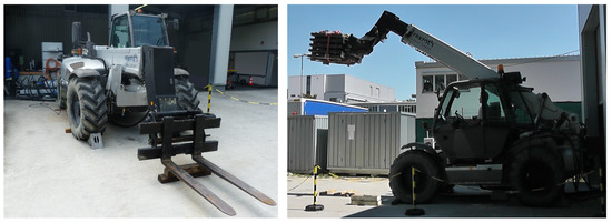
Figure 1.
Views of the telehandler that was used for demonstration—Left: front view with the electro-hydraulic rig visible in the back—Right: side view with a 2.5 t steel-plate load strapped onto the forks.
However, full integration of two new power-trains—the displacement-controlled concept of interest and a valve-controlled but electrified benchmark—into the telehandler is avoided. Instead, a stationary approach is pursued with an external rig that contains most of the added power-train components, as can be seen in Figure 2. This omits the effort of removing the non-required components—such as the combustion engine—and integrating new components into the limited space of the conventional machine chassis, which was not designed for this. Instead, only hydraulic and electric connections must be rearranged. Furthermore, this cuts down the time for changing between the two tested versions of the telehandler—electrified but purely valve-controlled benchmark and the version with a displacement-controlled boom. The effect of the omitted integration on the dynamic or energetic behavior is expected to be minor anyways.
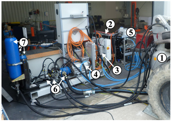
Figure 2.
Electro-hydraulic rig and hydraulic connections to the telehandler (1). Further components/assemblies: 680 V Battery (2), inverter (3), motor (4), air-liquid cooling unit (5), hydraulic pumps, and valve block (6), as well as four hydraulic accumulators (7).
The downside of the external-rig approach—compared to fully integrated approaches as in [12,18,19]—is the loss of mobility and the unrealistically long hydraulic lines. The latter can be regarded as a minor influence, but the loss of mobility has a major effect on the way that work cycles can be measured. Work cycles that combine implement movements and the driving function, such as loading earth with a bucket from a pile, cannot be directly measured. Therefore, an alternative approach for simulating such cycles with steel-plate loads and synthesizing loaded measurements and unloaded measurements is used and will be described in Section 4. The performed cycles might thus be artificial to a certain extent, but the authors are convinced that the characteristics that are important for the consumption in such cycles can be captured with this approach as well. Furthermore, this approach allows the measurement of a variety of different cycles with low effort, which adds more information for the analysis of the system performance.
2.3. Electric Drive System
The purpose of the electric drive system is to power the hydraulic pumps and to enable variable control of the rotational speed. For this purpose, a permanent-magnet synchronous machine designed for 700 V heavy-duty applications [20] has been selected. Its nominal power is 90 kW, which turned out to be slightly oversized for the cycles that were performed in this study, especially considering its extensive overload capabilities. The electric machine is powered and controlled by an inverter of the matching power class [20]. Its controller area network (CAN) interface allows the reading of current and voltage values of the direct current (DC) bus with a sample time of 10 ms. These values are used in this study to measure energy consumption. A comparison of this approach to using a dedicated power analyzer was previously performed on another test bench and showed sufficient accuracy of the CAN-based method for the purpose of cycle-consumption analyses. The approach is further confirmed by [15], where the inverter is used to measure the power consumption of an electro-hydraulic system as well.
Due to this method, the battery and the cooling system are not considered in the power consumption, but nevertheless, they are crucial for the functionality of the test setup. The nominal voltage of the battery is 680 V, and during the tests, it was held between 650 and 750 V. The battery is connected to the inverter via a power distribution unit, which is also the interface to the onboard charger that is mounted on the rig. Furthermore, a cooler chills down a water–glycol mixture that is pumped through the motor, inverter, and onboard charger for cooling. The cooling lines in blue, the 700 V cables in orange, and all other aforementioned components are shown in Figure 2.
2.4. Hydraulic System
In order to rate the energy consumption of the improved, displacement-controlled concept, a conventional, purely valve-controlled setup has been built up first for performing reference consumption measurements. Following this, the telehandler and rig were transformed into an improved setup, which was facilitated by the open design of the rig. Both setups differ only in the design of the hydraulic systems, which are explained here.
2.4.1. Purely Valve-Controlled Reference Setup
The reference system is supposed to represent the state-of-the-art approach for electrifying HDMMs. The first electrified series machines on the market were launched only in the last few years, and the number of models is still limited, but so far, all OEMs seem to stick to the same hydraulic systems that were previously used on diesel-driven machines [21]. In particular, LS systems are most commonly used as they can adjust the pump pressure and flow, which leads to higher efficiencies compared to open-center systems with constant volume flow, for example.
Since an LS system was used on the original telehandler as well, all existing valves were utilized for the reference setup. Counterbalance valves are used to handle overrunning loads and to handle pipe ruptures safely. They are mounted right onto the cylinders—on the piston side for the telescope as well as tilt cylinders and on both sides for the boom, which has two parallel cylinders. The motion of all actuators is controlled by a multi-function valve block with post-compensated control valves.
The significant difference from the original telehandler is the EM-driven and electronically controlled Rexroth A10VO [22,23] LS pump as a replacement for the original diesel-driven pump with a fixed LS-control setting. Due to the longer hydraulic lines, the LS margin had to be slightly increased compared to the original value in order to achieve the same maximum actuator speeds and it is 23 bar now. The adjustment of the margin was facilitated by the electronic control of the pump, which allows parameter changes via software [22]. The software also realizes a pressure cut-off function at 270 bar and a flow limitation of 150 L/min—both limits have been adopted from the original hydraulic system of the telehandler.
Moreover, the electric prime mover enables a more variable speed control than combustion engines, which is used to let the pump rotate with speeds that are as low as possible. More precisely, the controller estimates the required pump flow from the measured joystick control pressures and adds a small margin to take uncertainties and pump losses into account. The flow value is then divided by the maximum pump displacement to obtain the desired rotational speed for the EM control. Without any detected joystick deflection, the EM reaches a standstill, and the starting speed at a minimum joystick deflection is 500 rpm, which assures sufficient lubrication of the friction interfaces inside the pump. This minimum-speed approach assures that the pump works most of the time close to its maximum displacement, which especially improves the volumetric efficiency. Previous tests of this approach with the same test setup showed a reduction of the overall electro-hydraulic system consumption in the range of 0–14% depending on the work cycle and compared to a constant-nominal-speed approach. Moreover, the idling losses can be reduced to zero with the variable speed control. Finally, it should be noted that this approach works especially well in this system because the control valves are post-compensated. Accordingly, underestimating the required pump flow does not lead to a full stop of the actuator with the highest load pressure as it would in a system with pre-compensated valves.
2.4.2. Pump-Controlled Boom for the Improved Setup
To obtain the actual setup of interest, the reference setup is improved by mounting an additional closed-circuit pump to the drive shaft for the displacement control of the boom function and, thus, for increased efficiency. The whole pump-motor assembly can be seen in Figure 3 on the left side. Mounted right onto the EM, in blue, is the Rexroth A10VO variable-displacement open-circuit pump [23] with 71 cm3 maximum displacement, which is used for the LS supply and was the only pump mounted to the EM for the reference setup, which was described in the previous section. Looking at the other added components in line gives an idea of how much more installation space is needed right next to the implemented EM of an HDMM that applies such a concept—an important aspect of system-integration work. Next in line is the black Rexroth A10VG [24] variable-displacement closed-circuit pump with 63 cm3 maximum displacement.
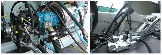
Figure 3.
Added hydraulic components—Left: (in the order from left to right) charge pump, closed-circuit pump for boom control in black with valve block attached, and open-circuit LS pump in blue—Right: load-holding valves for left boom cylinder, connected to rod and piston side via short hoses (visible on the right side of the boom cylinder is the compensation cylinder, which is connected to the tilt cylinder for parallel movement of the tool).
The third and final pump in the line is a small fixed-displacement gear pump with only 8 cm3. It is responsible for feeding back oil into the closed circuit that has been lost through external leakage of the A10VG pump. It is sized to feedback the full external leakage flow into the system even at the worst-case operation condition of the A10VG pump. Still, the pump can be much smaller than charge pumps that are commonly used in close-circuit drive applications—14.9 cm3 would be the standard size for a 63 cm3 A10VG—since it does not have to supply the control-valve flow for the pump. This is performed by the low-pressure accumulator, which will be discussed in one of the following paragraphs.
Due to a careful selection and sizing of the pumps, the maximum operatiing conditions of all three pumps match quite well, and they can each make the most of their power potential. The maximum torque rating of the through-shaft in the standard A10VO pump, for example, is just sufficient to operate the two other pumps at their maximum operating pressures and displacements, which means that no extra power-split gearbox is required. The maximum operating speed of the whole assembly is 3000 rpm in order to make use of the maximum flow capability of the A10VG. However, the A10VO with a lower nominal operation speed of 2550 rpm can still tolerate this without cavitation since its maximum flow is limited through the software, as described in Section 2.4.1. Furthermore, the minimum operating speed limit is 500 rpm in this setup as well since all three pumps require this for proper lubrication.
Next to the pump as the heart of the circuit, several auxiliary components are required for the closed-circuit control of the boom cylinders, which can be seen in the schematics that are depicted in Figure 4. The schematics are mainly characterized by the closed-circuit design. Closed means that each cylinder port is directly connected to a pump port, and the return flow is not passing a reservoir before it enters the pump again. This design was chosen because it allows the handling of tilting loads without the high control effort and risk of abrupt motion, which would apply to the pump control with open circuits [25,26].
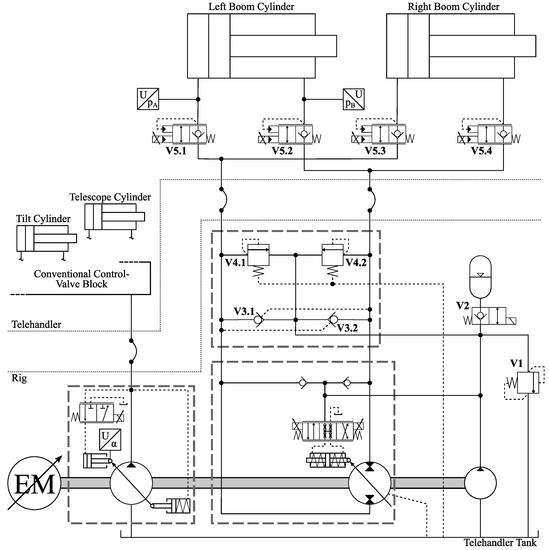
Figure 4.
Hydraulic schematics of the improved system with displacement-controlled boom and valve-controlled tilt, as well as telescope function; broken lines mark the two pump housings and the valve manifold.
However, the closed circuit has its issues as well—especially when it comes to handling the differential flow of the single-rod cylinders that are common for HDMMs. During extension, additional flow needs to enter the closed circuit, and during retraction, it needs to leave it. In this setup, an accumulator is used as a passive solution for this. The pilot-operated check valves V3.1 and V3.2 (see Figure 4) realize that it is always connected to the low-pressure side of the circuit and not compromising the stiffness of the high-pressure side.
Furthermore, special attention must be paid to the sizing of the accumulator in this system. Its lowest pressure is reached at full extension and should still meet the 18 bar minimum requirement of the pump control valve, which is supplied by the accumulator as well. The highest pressure is reached when the 7 l pendulum volume is fully charged into the accumulator at full retraction. The original objective was to not exceed the 40 bar maximum limit of the control valve, which would have ended up with a reasonably small accumulator volume of 18 l. However, a total volume of 42 l—three 6 l and one 24 l accumulator, visible as number 7 in Figure 2—was used in the end in order to reduce the maximum pressure to 25 bar. The specific reason will be given in Section 3.3.
The remaining auxiliary valves in Figure 4 fulfill the following functions: V1 limits the pressure of the accumulator when it is fully charged, and the charge pump flow exceeds the external leakage. V2 is normally closed to prevent the accumulator discharging the external pump leakage during standstill; it is actively opened as soon as the EM starts spinning. V4.1 and V4.2 with vented spring chambers are added since the relief valves in the A10VG pump casing have low pressure acting in the spring chambers, which means that the relief setting depends on the accumulator charge state and is not constant in this setup. Those added valves are located in an extra manifold that is flanged directly onto the A10VG and also accommodates V3.1 as well as V3.2. The original relief valves have been deactivated. Finally, V5.1, V5.2, V5.3, and V5.4 are added to lock the cylinders at a standstill. Otherwise, the pump leakage had to be actively compensated for in order to keep the cylinders at a constant position under load. For this function, switching valves would actually be sufficient, but due to better availability, proportional so-called eValves from Rexroth [27] have been used. Advantages are additional degrees of freedom for smooth control, and they fulfill the safety function of limiting the maximum lowering speed in the event of a pipe rupture. For this reason, they are also mounted as close to the cylinder as possible. As can be seen in Figure 3, short hoses still had to be used since there was no interface for mounting them right onto the cylinders.
3. Displacement Control and Dynamic Performance
After presenting the hardware of the system in the previous section, this part focuses on the displacement control of the boom cylinders, especially on the insights that were obtained from applying it on a real machine and tuning it in order to achieve an operator-friendly machine behavior.
3.1. General Control Approach
The basic idea of displacement-controlled cylinder movement—as it was first proposed by Rahmfeld and Ivantysynova for combustion-engine-driven machines [7]—is that the direct connection between the high-pressure pump and cylinder sides allows the control of the cylinder speed by changing the pump displacement. As can be seen in the equation, the cylinder speed v is proportional to the relative pump displacement if the loss term , which the control software estimates from lookup tables, is compensated for:
This relationship is used to transform the joystick command value of the operator, which corresponds to a desired cylinder speed, into a desired relative displacement. For that purpose, the high-pressure cylinder area A is detected by sensing both cylinder pressures, as shown in Figure 4, and by reading the actual rotational speed n from the inverter CAN message. The maximum pump displacement is constant, and the loss term is estimated, as mentioned before. Moreover, a pressure cut-off function reduces the desired displacement value gradually when the pump pressure rises close to the relief-valve setting in order to reduce energy losses at those valves whenever the cylinder is blocked or at one of the end stops.
The pump displacement itself is controlled in a pure feed-forward manner by changing the electric current of the coils at the pump-control valve, shown in Figure 4, according to its characteristic curve in the data sheet [24]. The dynamics of the standard A10VG without any extra damping orifice in the control lines showed to be sufficient in tests. The main criteria has been to achieve shaking movements with the boom at a frequency as high as it could be reached with the valve-controlled reference setup, which was possible.
Further, the improved system with a combination of valve- and displacement-controlled actuators follows a minimum-speed approach for the EM control. This assures that the desired cylinder speed can be achieved while the pumps are working with a displacement as high as possible, which is more efficient. Nevertheless, due to the common shaft for the A10VO and A10VG, one pump can also be forced to work at lower displacements if the other pump requires a higher speed. Furthermore, it should be noted that the speed rising and falling rates have been limited to 4000 rpm/s absolute. With higher rates, the joystick reacted too dynamically, and any machine oscillation was amplified by the operator who is sitting on the machine and holding the joystick simultaneously. For work cycles that required very precise movements, the rate has been even lowered down to 2000 rpm/s absolute in order to add damping.
3.2. Actuation of Load Holding Valves
Passive load holding of pump-controlled cylinders has been the subject of several other publications, such as [28,29], which is why the approach that was successfully used for the experiments in this study and its performance are explained as well. As shown simplified in Figure 4, pilot-operated proportional 2/2 directional valves—the eValves [27]—are used. During standstill, the normally closed valves do not require any actuation, and during cylinder movements, their coils can simply be fully energized to allow flow in the return direction. The challenging part is the transition between the two states.
Closing the valves when at a standstill is rather simple as well. The valves need to switch, and the pump needs to swivel back simply fast enough, which was the case in the tests. Going from a standstill to movement, on the other hand, has the potential for jerks because the volume in the lines between the pump and cylinder needs to be pressurized first before the pump can control the movement.
For resistive movements, the check function of the load-holding eValves prevents any jerks. The high-pressure side is the supply side of the cylinder, and the eValve on this side is not energized at all. Thus the eValve can keep holding the load until the pump manages to pressurize the oil volume in front of the valve and the movement starts. No problems but a smooth and timely start of the movement could be seen with this approach during the tests.
However, regenerative loads that require the A10VG to operate as a motor are more challenging. In this case, the cylinder load needs to pressurize the line volume, and only the valve can control the speed of this process. To prevent this from happening too fast, in the form of a jerk, a rate limit is implemented in control for the opening signal of the valve. With a rate limit of 1%/ms in combination with the natural valve dynamics, a jerkless, yet fast response could be achieved. Furthermore, fine tuning of the lookup table is required to achieve a smooth starting point of the motion at which the pump must exactly compensate for its own leakage and work as a pump until the desired cylinder flow exceeds the leakage.
3.3. Mode Switching Issues
One major issue, which appeared during the first tests of the system and could—without more extensive adaptations—only be handled by the compromise of drastically increasing the accumulator volume, is mode switching during the lowering of the boom. An analysis of this problem is given in this section.
As explained in Section 2.4.2, the accumulator must always be connected to the low-pressure side of the circuit. Whenever the high-pressure side changes due to a change in the cylinder force, the pilot-operated check valves also passively switch the side at which the accumulator can exchange flow in both directions. This switch is unproblematic as long as the amplitude of the force change is large and the force is not close to the switching point—neither before nor after the change. An example of this is shown in Figure 5, where the force changes significantly when the operator presses down the boom against a box in front of the telehandler, and its front axis lifts slightly up into the air. The speed decreases only slightly for a moment in which the pump flow needs to be adjusted, but the operator could hardly notice any change in speed.
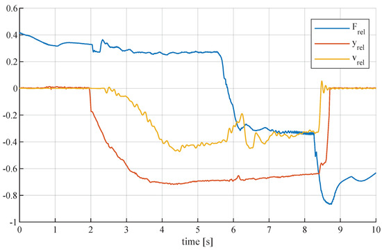
Figure 5.
Acceptable speed behavior of displacement-controlled boom cylinders during mode switching that is forced by changing from resistive lowering to pushing up the front axis of the telehandler; 600 kN is the reference for the relative combined cylinder force ; is the joystick signal; and 150 mm/s is the reference for the relative cylinder speed .
The behavior is, however, different if the load force is close to the switching point and only a small change in load is able to initiate a mode switch. With the experimental setup of this study, this is, unfortunately, the case when lowering the empty telehandler boom with a fully retracted telescope. The load on the cylinders is so low in this case that the switching point at the pilot-operated check valves can be reached simply by increasing the lowering speed, which increases mechanical as well as fluid friction and lowers the load force on the cylinders even further.
For a detailed explanation of the relevant effects and to understand how frequent mode switching can be avoided, the simplified schematics in Figure 6 are presented, including measured values for pressure and flow during the critical mode switching situation.
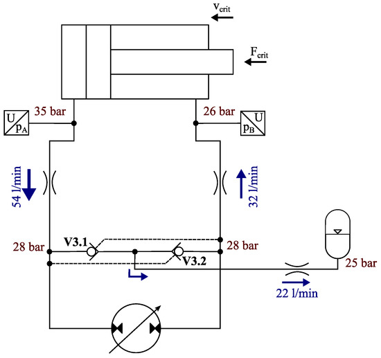
Figure 6.
Critical load and speed condition while lowering the empty boom at which small changes in cylinder load or speed result in mode switching (ca. 30% of maximum lowering speed and 28 °C oil temperature); the two parallel cylinders are simplified as one cylinder, and the values are obtained from measurements.
The flow directions that are indicated by blue arrows result from the direction of cylinder movement—retraction in this case. Concerning the pressure, the only value in the system that does not depend on speed and load is the accumulator pressure—25 bar—which is defined by the charge state. Assuming that the system is currently in the regenerative mode, V3.2 will be forced open, and flow is entering the accumulator coming from the pump, which results in a slightly higher pressure of 28 bar at the right pump port. This pressure drops down on the way from the right pump port to the rod-side cylinder chamber. The resulting pressure depends on the amount of flow as well as the restrictions in the line and at the holding valves—in this case, it is 26 bar. This pressure, together with the load force and mechanical cylinder friction, defines the required piston-side pressure of the cylinder, which needs to be only as high as 35 bar under the measured conditions. Finally, the pressure at the left pump port and in front of V3.1 results from the pressure drop in the line between the pump and the piston-side chamber of the cylinder. The measured drop down to 28 bar is quite high. The consequence is that the pressures at both pump ports and in front of both V3 valves are close together and make the system unstable. Only small changes in the cylinder speed, which influences the cylinder friction as well as the amounts of flow and thus line losses, in the oil temperature, which influences the line losses as well, or in the load force can lead the system from the regenerative mode with V3.2 open to the restive mode with V3.1 open or vice versa, respectively.
The problem is that such small changes can frequently appear during normal operation of the boom—-specifically during empty lowering—and the result is cylinder speed oscillations with amplitudes in the range of 7 mm/s, which is hardly manageable by the operator. As a workaround for the experiments in this study, the maximum accumulator pressure has been reduced from initially 40 bar—at which the issues would appear at even lower speeds and also higher loads—to 25 bar by increasing the accumulator volume from 18 to 42 l; furthermore, all measurements without load were performed with preheated oil at a temperature between 50 and 60 °C, which reduced the line losses and could prevent the mode switching oscillations.
3.4. Discussion of Control Performance and Possible Improvements
As explained in the previous sections, the final control behavior of the displacement-controlled test setup was satisfactory; however, there are aspects that should be discussed with reference to a broader, potentially commercial and economic application of this concept. Along with this discussion, proposals for further improvement are introduced.
First of all, it should be mentioned that the evaluation of the control performance in this setup is strongly linked to the fact that the telehandler is operated by a human. On the one hand, this puts more stress on a smooth, continuous, and predictable transfer behavior from the input signal to cylinder movement. On the other hand, the dynamic requirements are lower compared to automated operations with closed-loop controllers. To achieve stable performance in the latter case, further measures, e.g., for higher stiffness, might be required. However, at least for human-operated mobile applications, as in this setup, the experiments confirmed Ivantysynova’s statement in [30] that pump control can achieve comparable control bandwidths to valve control—even without using a displacement feedback signal.
Concerning the relatively simple minimum-speed control approach for the EM, more sophisticated options could be applied that take, for example, efficiency maps of the EM into account and can lead to extra savings, as shown in [10]. The amount of extra savings depends on the cycle and can be assumed to be rather small, which is why the authors stuck to the minimum-speed concept. Still, such improvements should be considered for potential commercial applications of the concept since they do not necessarily need extra hardware, only software development effort.
A potential for simplification can be found in the design of the load-holding valves. As explained in Section 3.2, the proportional control of the eValves is only used in one load quadrant for an opening rate limit. If such a rate limit can be achieved with an on-off version of the eValve, the component costs could be reduced. Another solution for using on-off valves would be a pressure control of the pump during the valve transitions, as proposed in [28], which could also improve the response time even further. This should be considered for further improvements. Nevertheless, according to the experienced operator, the performance of the experimental setup as it is—even with the large compression volume caused by the long hydraulic lines—was already fully satisfactory for achieving a smooth yet dynamic start and stop of the boom motion and for performing the work cycles in this study.
A final discussion point for the control behavior is the mode switching issue, which has been fixed in the experimental setup only by drastically increasing the accumulator volume. If a new machine was designed, the following more fundamental and acceptable measures—which are derived from the analysis in Section 3.3—could be taken to avoid mode-switching issues of this kind:
- Shifting the switching point outside of the normal operation conditions
- –
- Increase in load pressure
- *
- Change in kinematics
- *
- Smaller cylinders
- –
- Reduction in maximum low pressure
- *
- Larger accumulator (performed in this study but not desirable)
- *
- Smaller cylinders and thus reduced pendulum volume
- *
- Pump-control-valve supply from high pressure and thus reduction in minimum low pressure
- *
- Alternatives to the conventional bladder-type accumulator (see suggestions in [31], for example)
- –
- Reduction in pressure drops in lines (at maximum speed, the current setup showed pressure drops of up to 15 bar between the piston sides of the cylinders and the pump)
- *
- Larger lines, fittings, ports, and valves
- *
- Smaller cylinders and thus lower line flows
- Reduction in oscillation risk
- –
- Actively controlled valves to replace V3.1 and V3.2 (see [32], for example) for applying switching hysteresis
- –
- Pressure sensors next to V3.1 and V3.2 to detect switching point instead of cylinder pressures
The main take away from this list is that smaller cylinders offer a high potential for reducing control and sizing issues in pump-control circuits as well as for reducing parasitic line losses. The resulting higher pressures could also be tolerated to a certain extent by standard A10VG units, which tolerate up to 300 bar constantly—30 bar more than the current maximum pressure limit that was adopted from the original telehandler setup.
4. Method of Comparing Cycle Consumption
As mentioned before, the stationary character of the test setup does not allow the measure of real work cycles, which usually involve driving and dumping loads. In order to measure cycles that are still realistic, a method is used that mimics the loading cycles that are of interest. First, each cycle is separated into two halves—one with a loaded boom and one without a load, which is feasible for most loading cycles. For measuring the half with a load, steel plates are strapped onto the telehandler forks, and an operator performs the movement as if they had, for example, a bucket full of earth. For the second half, measurements with an empty fork are performed, and the operator performs the movement as if they had just unloaded or dumped their load and wants to return to the loading or digging position.
The challenge is to combine the measurements of those two measured halves in order to obtain a consumption value for the full cycle that can be compared to the consumption of another setup. Especially challenging is the fact that the control valves are actuated by a hydraulic joystick and not by solenoids, which would allow the automation of the cycle movements. Instead, an experienced human operator was performing the tests, who could not follow the exact same trajectories each time but caused a certain vagueness. For that reason, each cycle half was measured ten times, and the average consumption values were formed according to the following equations.
The basis for the consumption analysis is the electric input power of the system. As explained in Section 2, the inverter is considered the system boundary, and its power can be measured indirectly through DC current I and voltage U. Furthermore, a difference is made between positive and negative power. Positive inverter power is required to drive the system and obtained with Equation (2). Negative inverter power , on the other hand, is available for charging the battery and calculated according to Equation (3).
Through integration, the amount of energy can be obtained that is required for driving the inverter (Equation (4)) during a specific measurement interval defined by the start and end times, and —in this specific case; one interval is a cycle half, as described above:
The same is performed to obtain the amount of energy that can be charged back into the battery during the measured cycle half:
As mentioned above, the trajectories and, thus, the performed work can vary between the measurements of the same cycle due to the human operator. For that reason, the output power of the system is also calculated in order to obtain a reference for the performed work in each cycle. For each considered actuator i, the mechanical cylinder output power—not considering cylinder friction—is calculated as follows:
In this equation, is the actuator speed obtained as the derivative of the position signal from a cable-extension sensor; and are the pressure and effective area of the piston-side cylinder chamber, while and correspond to the rod side.
Further, the input power at each actuator, which can potentially be used for recuperation, is quantified in a similar manner:
Taking into account the three actuators for boom, telescope, and tilt, the amounts of output energy and negative implement energy are calculated for each cycle half:
In the next step, all those energy amounts are used to calculate the relative consumption of each measured cycle half in the following way:
To obtain a more trustful result, an average relative consumption is calculated from the N-time repetition of each cycle-half measurement:
Following is an absolute consumption value for the whole cycle obtained by transforming the different values of each cycle into absolute values again by multiplying each with a reference value or , respectively. These reference values are the same for both setups and refer to the average value—formed from all repeated measurements of the reference setup—of the term , which was also used to form the relative consumption out of the absolute consumption in Equation (10). This way, an absolute average consumption for a full cycle can be obtained:
Calculating this value from the measurements with the purely valve-controlled reference setup () and for the measurements with the partially displacement-controlled setup () allows for the definition of the consumption reduction for the specific cycle:
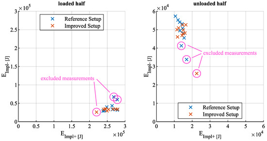
This approach can be justified by looking at Figure 7, which depicts the obtained and values for the two halves of an exemplary cycle and for both the purely valve-controlled reference as well as the improved, partially displacement-controlled setup. Up to two out of ten repeated measurements are neglected for each setup if the values differ significantly from the rest, as demonstrated in the plot. Accordingly, the sample size, N, in Equation (11) is 8, 9, or 10. The compactness of the remaining point clouds shows the similar, cycle-specific characters of the measurements, which is the basis for comparing them fairly.
Moreover, standard deviations are also calculated for each value according to:
This value visualizes how much the relative consumption can—according to the measurements and assuming a Gaussian distribution—differ from the average value that is used for the calculations in this paper. Furthermore, this deviation is propagated in order to estimate how much the consumption reduction can differ from the average value —for example, if an operator always performs a more efficient trajectory with the reference setup but a very inefficient trajectory with the improved setup for the same work cycle or task, respectively. In order to achieve the deviation of the reduction, first, the deviation of the absolute consumption is calculated:
Finally, the deviation of the reduction is
5. Measured Cycles and Discussion of Their Consumption
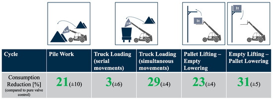
Because HDMMs can be used in very versatile ways—even two telehandlers of the same model can work very differently depending on the environment, task, and operator—it is important to evaluate the efficiency improvement of a new concept for a range of different work cycles that cover most of the common application cases [13]. Therefore, the table in Figure 8 shows the consumption reductions and their deviations according to Equations (13) and (16) for five different cycle types that were measured and will be analyzed in the following before the implications are discussed. For all cycles, it should be noted that the maximum extension speed of the displacement-controlled boom cylinders was limited by software to the same value that could be achieved with the valve-controlled cylinders in order to achieve similar conditions for both setups. From the hardware side, the displacement-controlled circuit could actually reach the same absolute speed during extension as for retraction.
5.1. Pile Work Cycle
In the measurements for this cycle, a full bucket of earth or any other pile material was simulated by steel plates with a total mass of 2.5 t that was strapped onto the forks, as shown in Figure 1 on the right. The cylinder movements mimic lifting the bucket out of the pile, moving the bucket down to a low drive position, and then lifting it up while tilting the bucket open above another imaginary pile. For the second half, the empty boom was moved as if the bucket was closed again and moved back down to the driving/loading position—no telescope movement was performed. This work pattern is common for telehandlers that work on construction sites or farms.
The relatively high average consumption reduction of 21% is not surprising since the boom movement makes up a major part of the total cycle time. However, the boom is only lowered without load, and the recuperation potential is low. This can also be seen by the fact that the inverter did not show any negative power during the cycle. The low amount of potential energy or kinematic energy of the rotational components was entirely absorbed by the accumulator or by losses in the system.
The reduction deviation of ±10% is quite high, which is caused by the vagueness in the cycle repetitions, as described in Section 4. However, it shows how the achievable reduction does not only depend on the hardware itself but also on how effective or ineffective the operator is controlling it in order to perform a certain work task.
5.2. Truck Loading Cycle
The load for the truck loading cycles was a 2.5 t mass as well. For the serial version, the movement is a series of lifting the boom out of the imaginary pile and then moving it in only tilt and telescope ways in order to unload the bucket at a constant bucket-tip height above the imaginary truck, which was marked by a rope between two piles in front of the telehandler. The empty movement was performed in reverse order. After measuring this version of the cycle, the low consumption reduction of only 3% on average surprised the authors, and a second version with more parallel movements was measured. In this version, the telescope starts moving while the boom is still lifting, and the operator also keeps lifting the boom slightly while the imaginary bucket is tilted.
The second cycle version led to a much higher average consumption reduction of 29%, which can be explained by different effects. First, the low consumption in the serial version is likely to be caused by the relatively long time—approximately 60% of the cycle—at which the boom is not moving at all. During this time, the efficiency of the system could not be improved since only the boom function was improved, which did not cause any losses in the reference setup during its standstill. Instead, the additional two pumps for the boom add idling losses since they are attached to the moving LS pump. Secondly, the improvement due to an individual extra pump for the boom is more significant when the boom and other actuators are moving simultaneously since the reference system has higher losses at the pressure compensators in this case. In the improved system, those are entirely eliminated for the boom and reduced for the other two implement functions.
Furthermore, a productivity improvement can be perceived with the improved setup and parallel movements. The two measured cycle halves were, on average, 25% shorter with the improved setup. The reason is that the LS-pump flow was frequently saturated in the reference setup, which does not happen with the additional pump in the improved setup.
All in all, the comparison between the two cycle versions shows very well that the added value of a system improvement in terms of efficiency and productivity can, for certain work tasks, strongly depend on the operator.
5.3. Pallet Handling Cycles
The final two cycles in Figure 8 were both measured with a steel-plate load of 1 t on the forks, which is supposed to simulate a pallet being handled. In the first version, lifting the pallet to a high position, for example, a high shelf, and dropping it there is mimicked; the second half includes the empty lowering of the boom back to the position for picking up a new pallet. This movement involves a complete telescope extension but also a lot of boom movement. However, the recuperation potential is still rather low due to the empty forks during lowering. Accordingly, the savings of 23%—very similar to the pile-work cycle—are not surprising.
The second version, on the other hand, represents a cycle class with more recuperation potential due to an empty boom lifting and loaded lowering. The imaginary work environment in this cycle remains the same, but now, approaching the high position without load and picking up a pallet in order to lower it is simulated. The measurements of this cycle are also the only ones that show significant energy flows from the inverter back to the battery. The average consumption reduction of 31%—the highest value among all cycles—is well in line with this evident recuperation process taking place.
Cycles similar to those two pallet cycles might not be typical for the majority of telehandlers in the field. Nevertheless, the results show the potential of the displacement-control approach in terms of energy recuperation and what can be achieved if those cycles belong to the typical work-cycle mix of a telehandler or similar HDMM in a specific environment.
5.4. Discussion in Comparison to Related Studies
Now that the experimental results have been presented, it is of interest to put them in relation to the results that could be obtained in related studies and to see what new information could be gained. A special feature of the consumption measurements in this paper is that multiple different cycles have been tested under the same conditions, while most other experimental studies focus on one cycle only, as in [8,12,18], for example. Comparing the different cycles shows that the type of cycle, as well as the trajectory, and thus the operator behavior can have a significant impact on the consumption reduction that can be achieved with an improved concept—an effect that has already been stressed by the authors in their simulation-based studies [5,6,13]. This knowledge should be considered in future studies since it means that looking at only one cycle for a performance evaluation can lead to a very limited, over- or underestimated picture of the actual average performance of a concept—at least for HDMMs that are likely to perform a variety of different work cycles.
Accordingly, comparing the absolute numbers for the consumption reductions in this paper to those of other studies that were performed under different conditions, with different cycles or even different machine type can be misleading and should be done carefully. Since there is no other consumption study known to the authors that dealt with a pump-controlled telehandler, not to say an electrified pump-controlled telehandler, the reduction values in the range of 21–31% for four out of the five cycles are only roughly compared to other experimental studies that handled displacement-controlled HDMMs as well. Compared to fuel consumption reductions that could be achieved for loading cycles with displacement-controlled wheel loaders, specifically, 10% in [12] and 10–15% in [18], the reductions in this study appear high. A trivial reason is that the driving consumption was considered in the balance of the two other studies as well, but also the effect that electrification and pump-speed control reduce the idling losses in displacement-controlled systems might have an influence. Much higher fuel savings of 40% were achieved in [8] with displacement control on an excavator. However, all excavator functions were displacement-controlled, while in this study, only the telehandler boom is, and [13] already showed that conventional excavators tend to show higher potentials for loss reductions than loaders do.
However, more valuable than the limited comparison to other studies with different setups is putting the experimental results in relation to the two preceding simulation studies [5,13] that considered the same telehandler and hydraulic setups. In [5], the concept was already simulated with the telehandler and artificial work cycles. Of course, the cycles were not exactly the same cycles that were measured in this study, but the general work tasks were similar, which allows for the comparison of the simulated reductions with the measured values of three cycles. For the pallet cycles that are called B1 and B2 in [5], values that are 5% and 8% higher were simulated. This can be explained by the fact that the artificial cycles involved more simultaneous movements with higher speeds, which is in favor of the improved system, as aforementioned. This is confirmed by the simulated value for truck loading (cycle A in [5]), which is even 1% lower than the measured value for the second version of this cycle in this paper, which also had a focus on simultaneous movements.
The simulation study [13], on the other hand, was based on measured work cycle trajectories and loads—only the electro-hydraulic system was simulated. Cycle I in [13] corresponds to a mixture of the two pallet cycles in this study, and a reduction of 17% was simulated, which is lower than the measured values for both cycles. Furthermore, Cycle III in [13] is a truck loading cycle and probably somewhere in between the two versions that were measured in this study; its simulated reduction is also in between, with a value of 21%. The slightly lower simulated reduction values with the realistic, measured cycles show that it is unlikely that the electro-hydraulic simulation model contains any inaccuracies in favor of the improved system and more optimal results.
Accordingly, the experimental results show that the simulation studies did not overestimate the efficiency improvements of the partially displacement-controlled concept significantly. This means that also the related findings in [5,13] are plausible. Specifically, the cost effectiveness of the concept, which was derived from the simulation results in [5], is of high interest in this regard.
6. Conclusions
This paper presented an experimental study in which displacement control for improved efficiency is combined with valve control for cost reductions to move the implements of an electrified telehandler. Such an approach can be the key to technologically, as well as financially, enable the electrification of a wide range of HDMMs, and the experimental proof of this concept contributes to this goal. The paper demonstrates—visually—how the concept can be realized with conventional mobile electric as well as hydraulic components that enable a reasonably short payback time, as shown in a previous cost analysis [5]. Furthermore, the evaluation of the measured consumption reduction validates the simulation studies that are the basis of the said cost analysis as well as the statements in [13]. Moreover, the consumption analysis points out the efficiency influence of the work cycle type as well as the operator and the chosen trajectory for fulfilling a cycle—an aspect that is often neglected in other studies. Next to the consumption, the study focused on the dynamic performance of the displacement-controlled boom cylinder in combination with a variable-speed electric prime mover. The dynamics of the conventional pump, as well as the load-holding valves, were accepted by the operator right from the beginning, but mode switching turned out to be problematic. A workaround with an increased accumulator volume allowed the proving of the control behavior of the improved telehandler to be fully satisfactory for the operator anyways. Still, realizing solutions that enable smaller accumulator volumes, of which several have already been proposed in this paper, should be the focus of further studies on this subject.
Author Contributions
Conceptualization, D.F., C.B. and T.M.; methodology, D.F.; software, D.F.; formal analysis, D.F.; investigation, D.F.; resources, C.B.; writing—original draft preparation, D.F.; writing—review and editing, D.F., C.B. and T.M.; visualization, D.F.; supervision, C.B. and T.M.; All authors have read and agreed to the published version of the manuscript.
Funding
This project received funding from the European Union’s Horizon 2020 research and innovation program under the Marie Skłodowska-Curie grant agreement No. 858101.
Data Availability Statement
The essential data of this study are openly available in Zenodo at 10.5281/zenodo.7372664.
Conflicts of Interest
The authors declare no conflict of interest. The funders had no role in the design of the study; in the collection, analyses, or interpretation of data; in the writing of the manuscript; or in the decision to publish the results.
Abbreviations
The following abbreviations are used in this manuscript:
| CAN | controller area network |
| DC | direct current |
| EM | electric machine |
| HDMM | heavy-duty mobile machine |
| LS | load sensing |
References
- Abuowda, K.; Okhotnikov, I.; Noroozi, S.; Godfrey, P.; Dupac, M. A review of electrohydraulic independent metering technology. ISA Trans. 2020, 98, 364–381. [Google Scholar] [CrossRef] [PubMed]
- Linjama, M. Digital Fluid Power—State of the Art. In Proceedings of the 12th Scandinavian International Conference on Fluid Power, Tampere, Finland, 18–20 May 2011; pp. 331–353, ISBN 978-952-15-2517-9. [Google Scholar]
- Ketelsen, S.; Padovani, D.; Andersen, T.; Ebbesen, M.; Schmidt, L. Classification and Review of Pump-Controlled Differential Cylinder Drives. Energies 2019, 12, 1293. [Google Scholar] [CrossRef]
- Schmidt, L.; Ketelsen, S.; Brask, M.H.; Mortensen, K.A. A Class of Energy Efficient Self-Contained Electro-Hydraulic Drives with Self-Locking Capability. Energies 2019, 12, 1866. [Google Scholar] [CrossRef]
- Fassbender, D.; Brach, C.; Minav, T. Using Displacement Control for Single Cylinders on an Electric Mobile Machine—Improved Efficiency Versus Increased Component Costs. In Proceedings of the 13th International Fluid Power Conference, Aachen, Germany, 13–15 June 2022. [Google Scholar]
- Fassbender, D.; Minav, T.; Brach, C.; Huhtala, K. Improving the energy efficiency of single actuators with high energy consumption: An electro-hydraulic extension of conventional multi-actuator load-sensing systems. In Proceedings of the 17th Scandinavian International Conference on Fluid Power, SICFP’21, Linköping, Sweden, 1–2 June 2021. [Google Scholar] [CrossRef]
- Rahmfeld, R.; Ivantysynova, M. Energy Saving Hydraulic Actuators for Mobile Machines. In Proceedings of the 1st Bratislavian Fluid Power Symposium, Bratislava, Slovakia, 2–3 June 1998. [Google Scholar]
- Zimmerman, J.; Busquets, E.; Ivantysynova, M. 40% Fuel Savings by Displacement Control Leads to Lower Working Temperatures—A Simulation Study and Measurements. In Proceedings of the 52nd National Conference on Fluid Power, Las Vegas, NV, USA, 23–25 March 2011; pp. 693–701, ISBN 0942220498. [Google Scholar]
- Busquets, E.; Ivantysynova, M. A Multi-Actuator Displacement-Controlled System with Pump Switching–: A Study of the Architecture and Actuator-Level Control. JFPS Int. J. Fluid Power Syst. 2014, 8, 66–75. [Google Scholar] [CrossRef]
- Larsson, V.; Lejonberg, R.; Liselott, E. Control Optimisation of a Pump-Controlled Hydraulic System using Digital Displacement Pumps. In Proceedings of the 17th Scandinavian International Conference on Fluid Power, SICFP’21, Linköping, Sweden, 1–2 June 2021. [Google Scholar] [CrossRef]
- Kärnell, S.; Fernlund, E.; Lagerstedt, F.; Ericson, L. Pump-Controlled Actuators with Dump Valves. In Proceedings of the 17th Scandinavian International Conference on Fluid Power, SICFP’21, Linköping, Sweden, 1–2 June 2021. [Google Scholar] [CrossRef]
- Heybroek, K.; Palmberg, J.O. Evaluating a Pump Controlled Open Circuit Solution. In Proceedings of the 51st IFPE, Omnipress, NV, USA, 12–14 March 2008; pp. 681–694. [Google Scholar]
- Fassbender, D.; Brach, C.; Minav, T. Energy-Efficiency Comparison of Different Implement Power-Train Concepts to Each Other and Between Different Heavy-Duty Mobile Machines. In Proceedings of the 2022 IEEE Global Fluid Power Society PhD Symposium, Naples, Italy, 12–14 October 2022. [Google Scholar]
- Benić, J.; Karlušić, J.; Šitum, Z.; Cipek, M.; Pavković, D. Direct Driven Hydraulic System for Skidders. Energies 2022, 15, 2321. [Google Scholar] [CrossRef]
- Qu, S.; Zappaterra, F.; Vacca, A.; Liu, Z.; Busquets, E. Design and Verification of an Open-Circuit Electro-Hydraulic Actuator System with an Integrated Electro-Hydraulic Unit. In Proceedings of the 13th International Fluid Power Conference (13. IFK), Aachen, Germany, 13–15 June 2022. [Google Scholar]
- Imam, A.; Rafiq, M.; Jalayeri, E.; Sepehri, N. A Pump-Controlled Circuit for Single-Rod Cylinders that Incorporates Limited Throttling Compensating Valves. Actuators 2018, 7, 13. [Google Scholar] [CrossRef]
- Hutcheson, J.; Abrahams, D.; Green, M.; Rampen, W. Motion Control of a Hydraulic Cylinder with a Digital Displacement Pump-Motor. In Proceedings of the 13th International Fluid Power Conference (13. IFK), Aachen, Germany, 13–15 June 2022. [Google Scholar]
- Schneider, M.; Koch, O.; Weber, J. Green Wheel Loader—Improving fuel economy through energy efficient drive and control concepts. In Proceedings of the 10th International Fluid Power Conference, Dresden, Germany, 8–10 March 2016; pp. 63–77. [Google Scholar]
- Linjama, A.M.; Tammisto, M.J. Hydraulic hybrid working machines project—lessons learned. In Proceedings of the The Sixteenth Scandinavian International Conference on Fluid Power, Tampere, Finland, 22–24 May 2019; pp. 423–437, ISBN 978-952-03-1302-9. [Google Scholar]
- Bosch Rexroth AG. eLion Electrification Portfolio by Bosch Rexroth. Available online: https://www.boschrexroth.com/en/xc/transforming-mobile-machines/electrification/elion-portfolio/ (accessed on 14 November 2022).
- Fassbender, D.; Zakharov, V.; Minav, T. Utilization of electric prime movers in hydraulic heavy-duty-mobile-machine implement systems. Autom. Constr. 2021, 132, 103964. [Google Scholar] [CrossRef]
- Bosch Rexroth AG. Versatile Working Machines Thanks to Electronic Control of Open-Circuit Pump (Press Release). 2021. Available online: https://m.boschrexroth.com/en/xc/company/press/index2-41728 (accessed on 14 November 2022).
- Bosch Rexroth AG. A10VO Series 32 (Data Sheet RE 92705). Available online: https://www.boschrexroth.com/documents/12605/25209043/re92705_2021-08-25.pdf/11a5ddfd-097d-3004-4aaa-420a638d9184 (accessed on 14 November 2022).
- Bosch Rexroth AG. A10VG Series 10 (Data Sheet RE 92750). Available online: https://www.boschrexroth.com/documents/12605/25209043/re92750_2020-03-03.pdf/dbb6b049-f973-d8b0-4654-e574803b104d (accessed on 14 November 2022).
- Heybroek, K. On Energy Efficient Mobile Hydraulic Systems: With Focus on Linear Actuation. Ph.D. Thesis, Linköping University, Linköping, Sweden, 2017. [Google Scholar] [CrossRef]
- Michel, S. Elektrisch-Hydrostatische Kompaktantriebe Mit Differentialzylinder für die Industrielle Anwendung. Ph.D. Thesis, Technische Universität Dresden, Dresden, Germany, 2021. [Google Scholar] [CrossRef]
- Bosch Rexroth AG. Compact, Performing, Flexible, Energy Saving: E-Valve (Data Sheet RE 92705). Available online: https://apps.boschrexroth.com/products/compact-hydraulics/ch-catalog/pdf/E-VALVE%202.5_RE18309-23.pdf (accessed on 14 November 2022).
- Hagen, D.; Padovani, D. A Method for Smoothly Disengaging the Load-Holding Valves of Energy-Efficient Electro-Hydraulic Systems. Proceedings 2020, 64, 36. [Google Scholar] [CrossRef]
- Padovani, D.; Ketelsen, S.; Hagen, D.; Schmidt, L. A Self-Contained Electro-Hydraulic Cylinder with Passive Load-Holding Capability. Energies 2019, 12, 292. [Google Scholar] [CrossRef]
- Ivantysynova, M. Displacement Controlled Actuator Technology—Future for Fluid Power in Aircraft and other Applications. In Proceedings of the 3rd International Fluid Power Conference, Aachen, Germany, 5–6 March 2002; pp. 425–440, ISBN 978-3826599019. [Google Scholar]
- Ketelsen, S.; Kolks, G.; Andersen, T.O.; Schmidt, L.; Weber, J. Bootstrap reservoir concepts for electro-hydraulic compact cylinder drives. In Proceedings of the 12th International Fluid Power Conference, Dresden, Germany, 12–14 October 2020; TU Dresden: Dresden, Germany, 2020; Volume 3, pp. 201–215. [Google Scholar] [CrossRef]
- Gøytil, P.; Padovani, D.; Hansen, M. A novel solution for the elimination of mode switching in pump-controlled single-rod cylinders. Actuators 2020, 9, 20. [Google Scholar] [CrossRef]
Disclaimer/Publisher’s Note: The statements, opinions and data contained in all publications are solely those of the individual author(s) and contributor(s) and not of MDPI and/or the editor(s). MDPI and/or the editor(s) disclaim responsibility for any injury to people or property resulting from any ideas, methods, instructions or products referred to in the content. |
© 2023 by the authors. Licensee MDPI, Basel, Switzerland. This article is an open access article distributed under the terms and conditions of the Creative Commons Attribution (CC BY) license (https://creativecommons.org/licenses/by/4.0/).