
5G-Based Industrial Wireless Controller: Protocol Adaptation, Prototype Development, and Experimental Evaluation

 ,
,  and
and 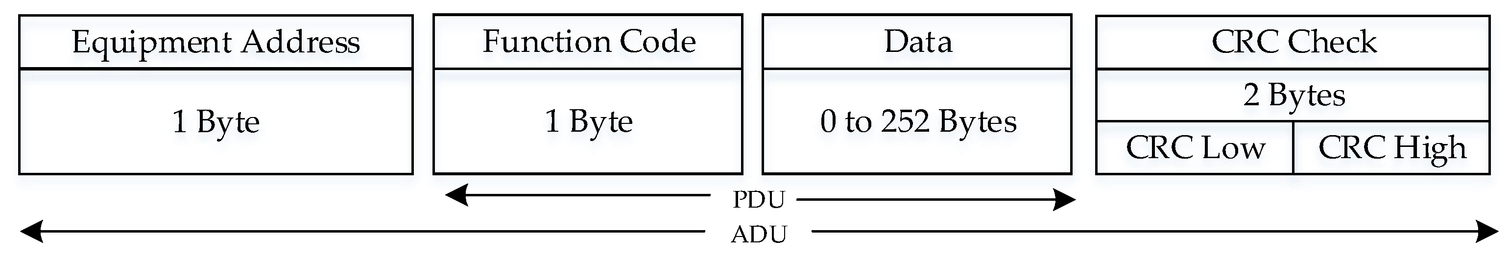
Abstract
1. Introduction
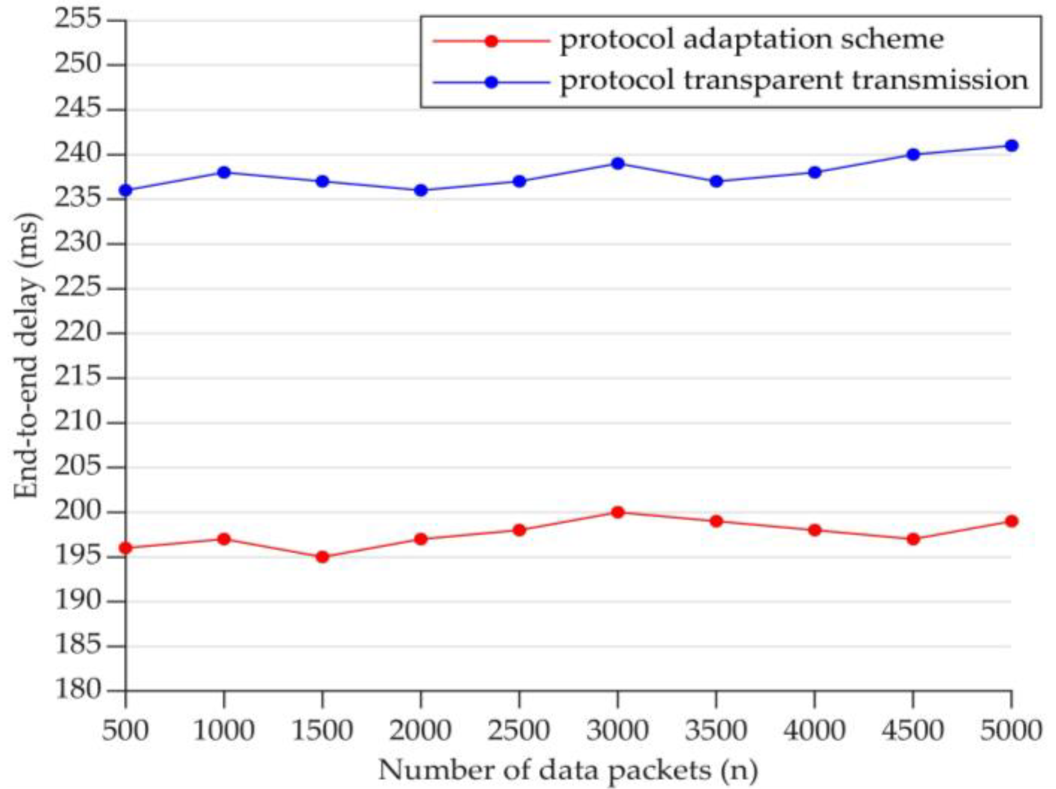
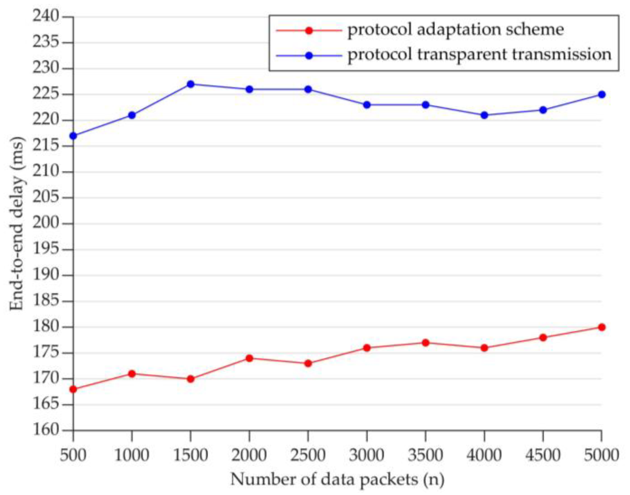
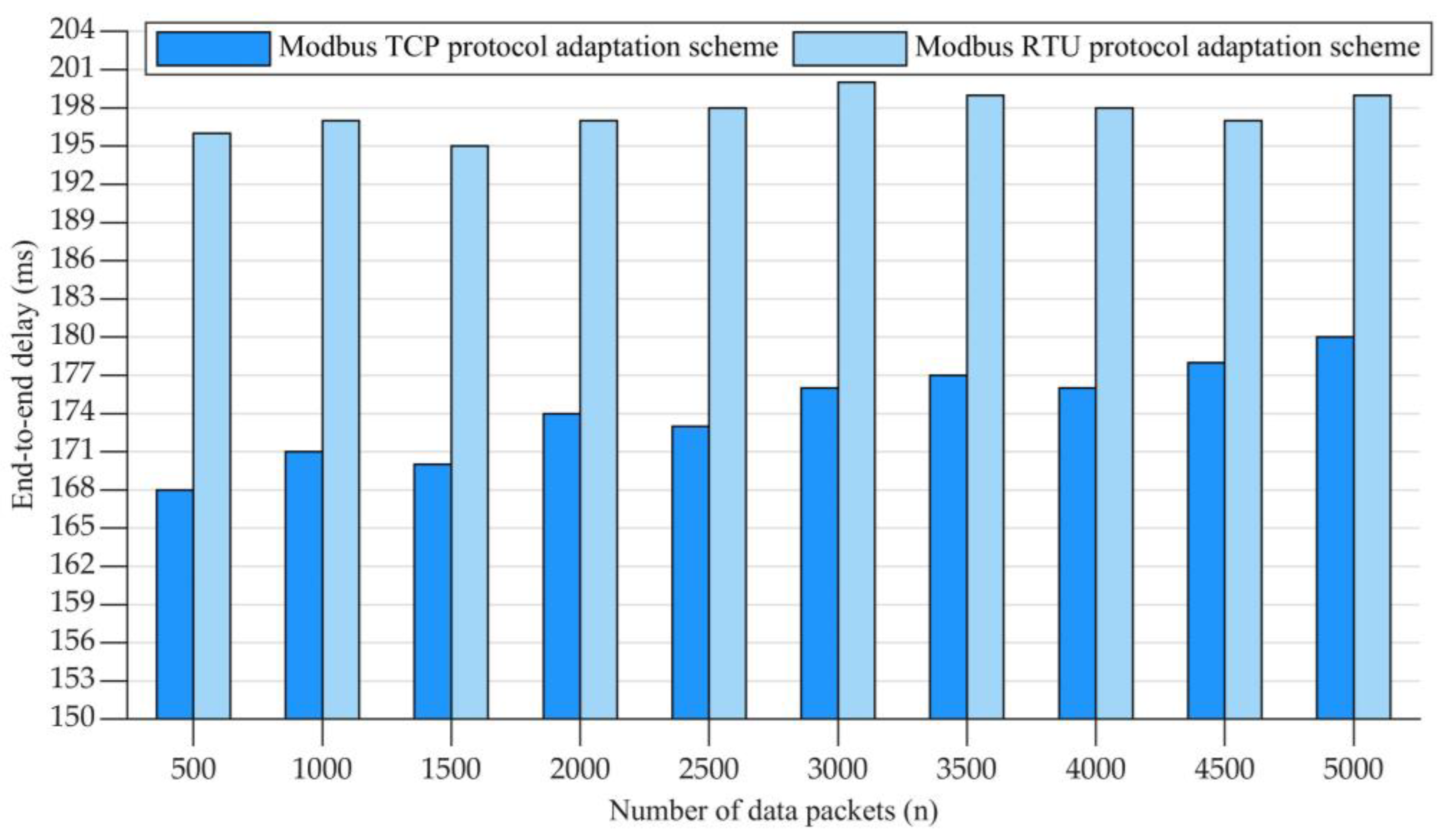
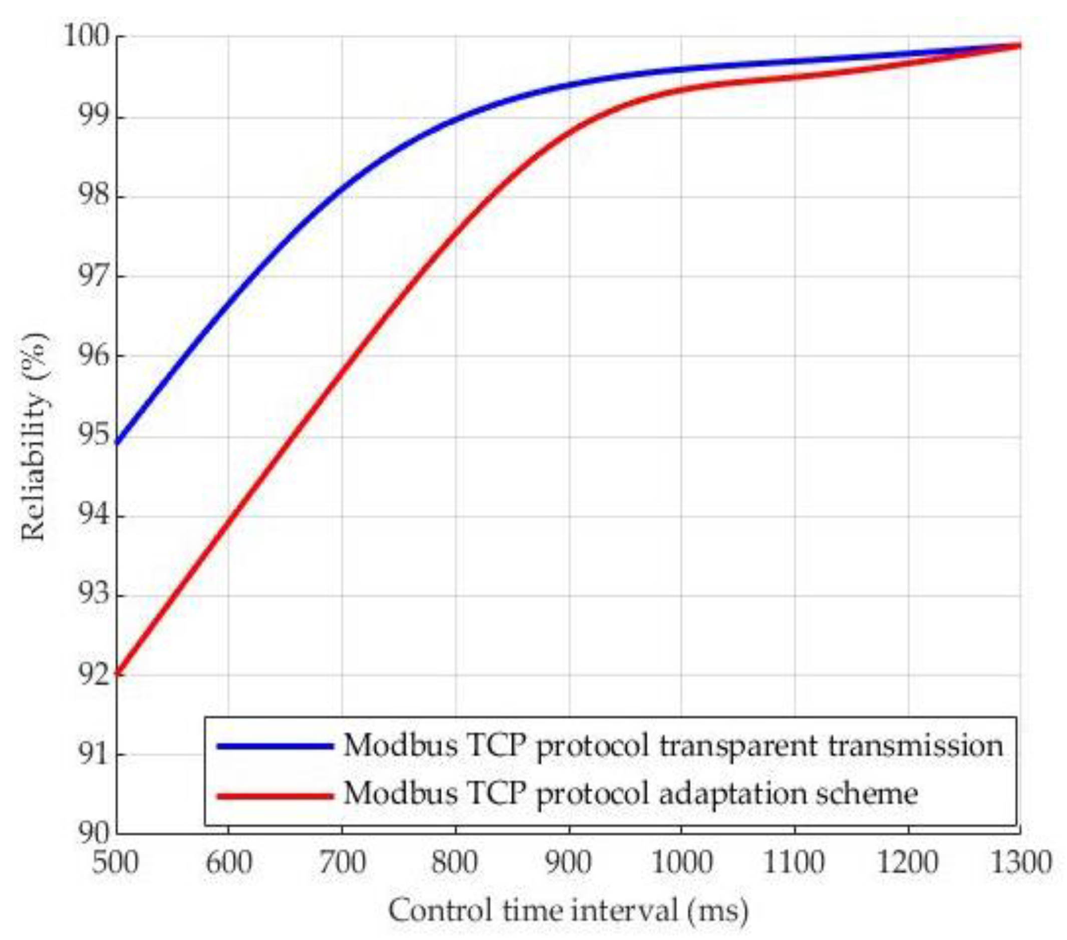
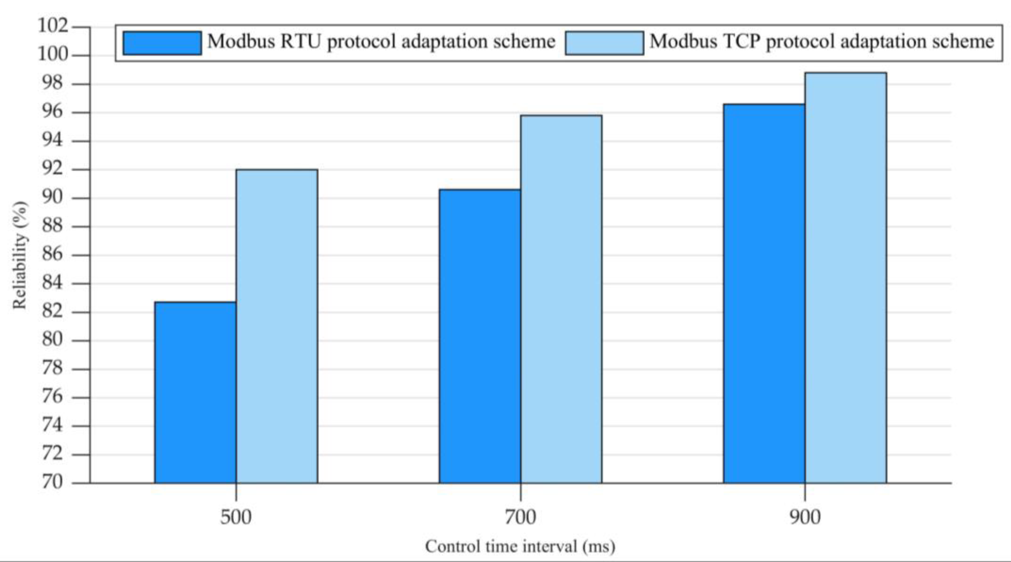
- We focus on the Modbus protocol, which is the most widely used in industry, and propose a protocol adaptation scheme with protocol resolution and conversion for both Modbus RTU and Modbus TCP. Meanwhile, we compare the proposed protocol adaptation scheme with the transparent transmission scheme.
- We develop a wireless PLC prototype system based on commercial 5G for the end-to-end transmission of Modbus RTU or Modbus TCP, where the network address translation is realized for the automatic matching of 5G.
- We perform extensive experiments to evaluate the effectiveness and superiority of the proposed scheme and developed prototype system.
2. Related Work
3. Protocol Analysis on Modbus and 5G
3.1. Modbus Protocol
3.1.1. Modbus RTU Protocol
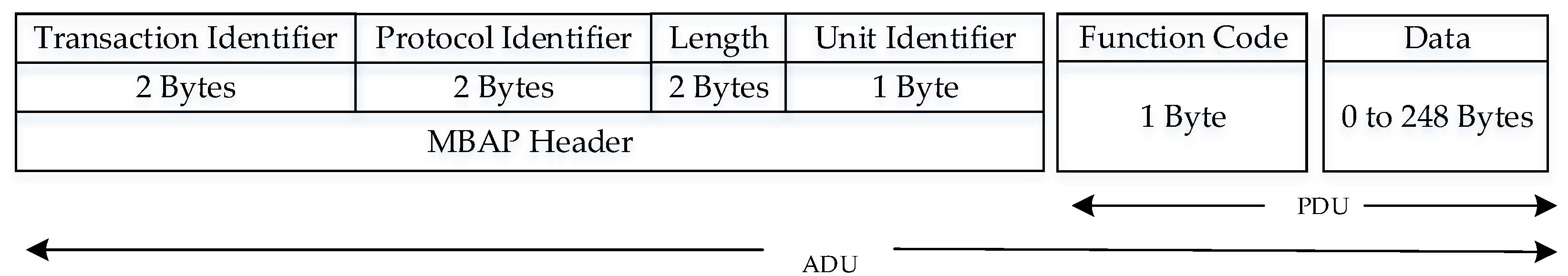
3.1.2. Modbus TCP Protocol
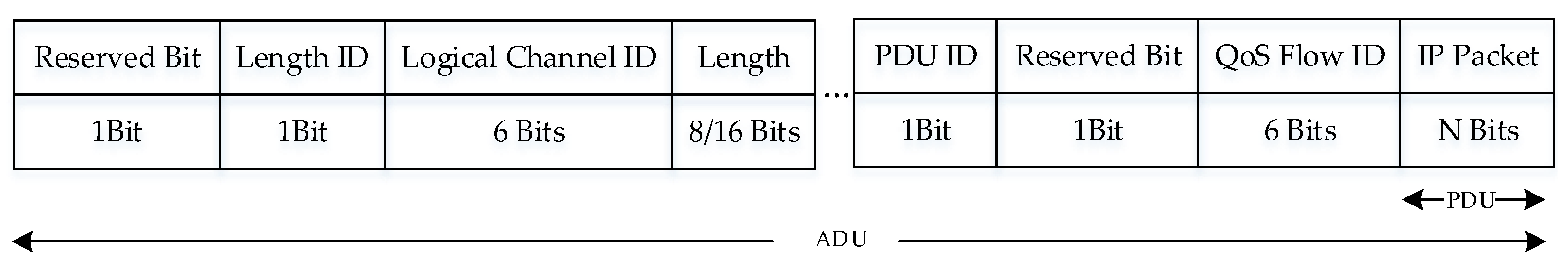
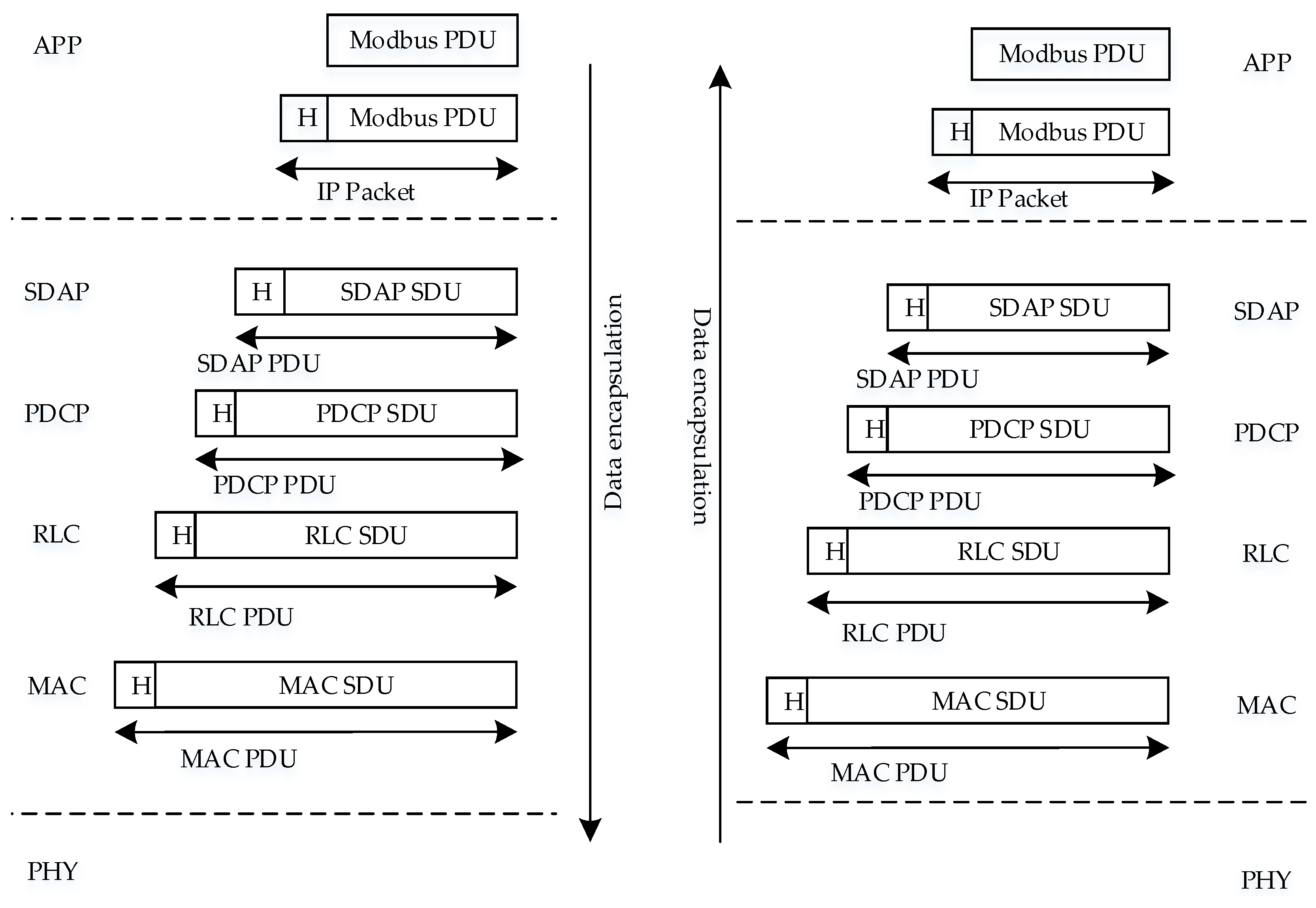
3.1.3. 5G Protocol
4. Protocol Adaptation for Modbus and 5G
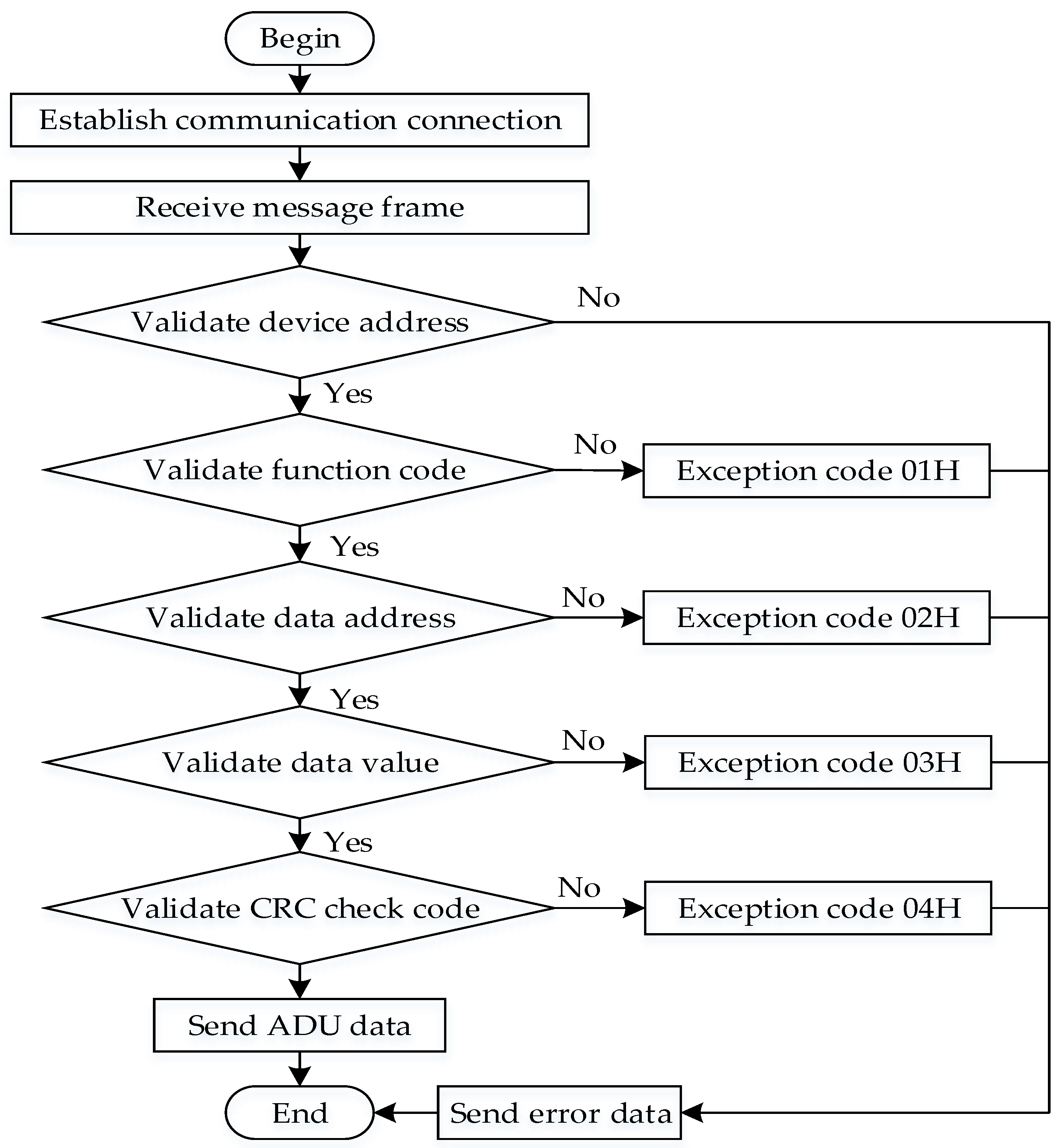
4.1. Protocol Adaptation for Modbus RTU and 5G
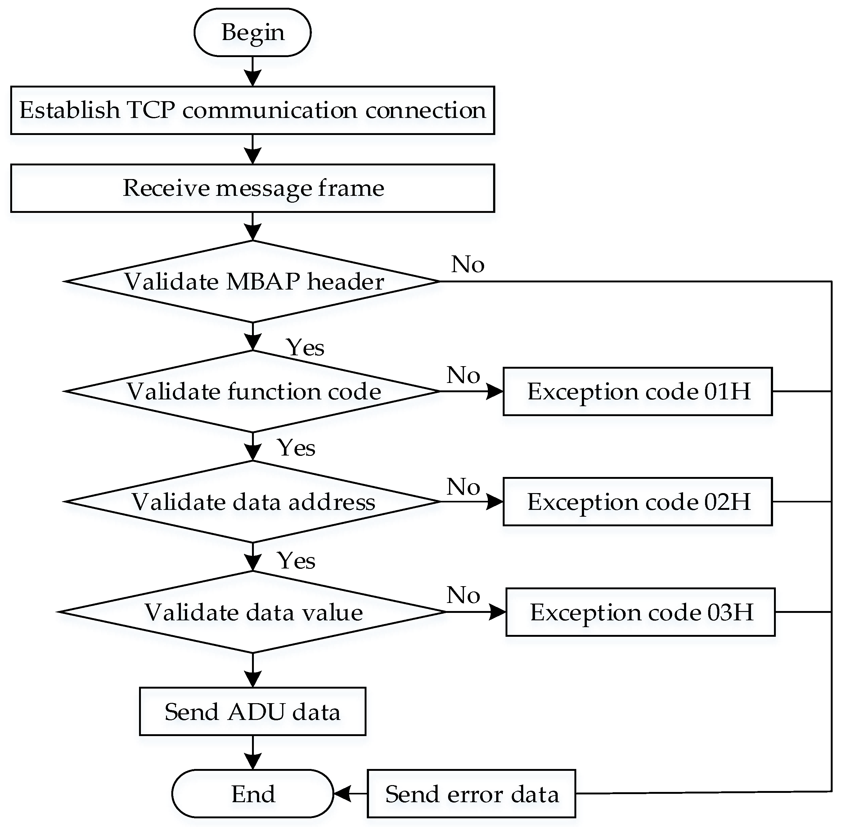
4.2. Protocol Adaptation for Modbus TCP and 5G
5. Prototype Development for Wireless PLC
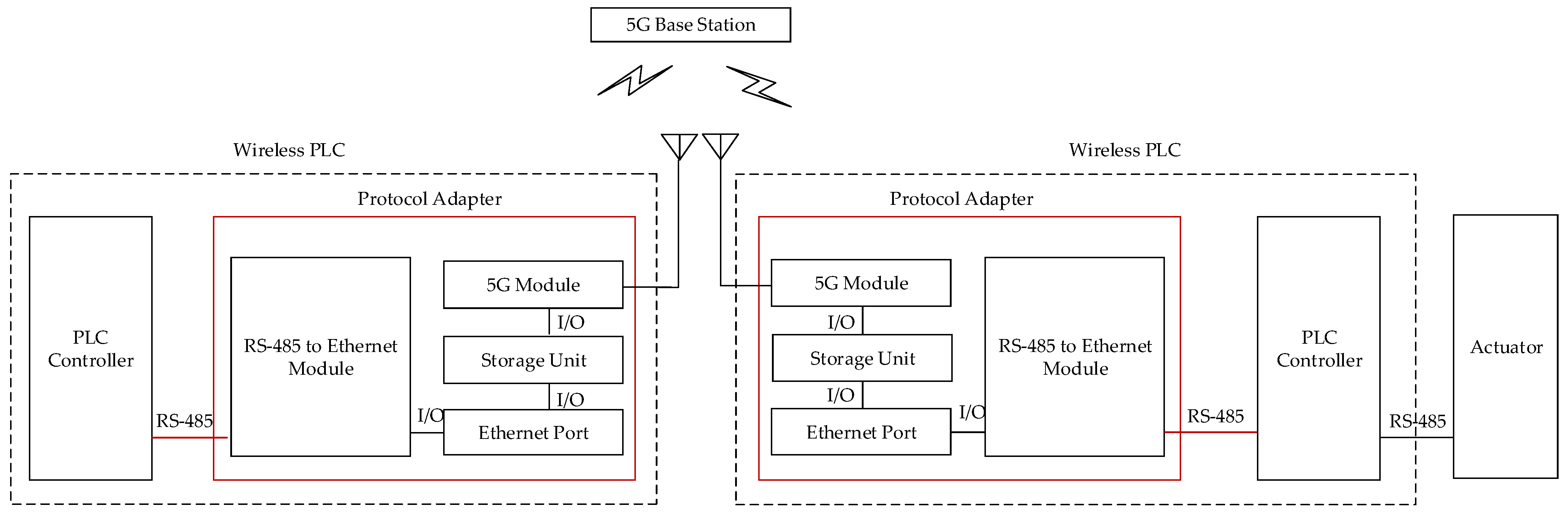
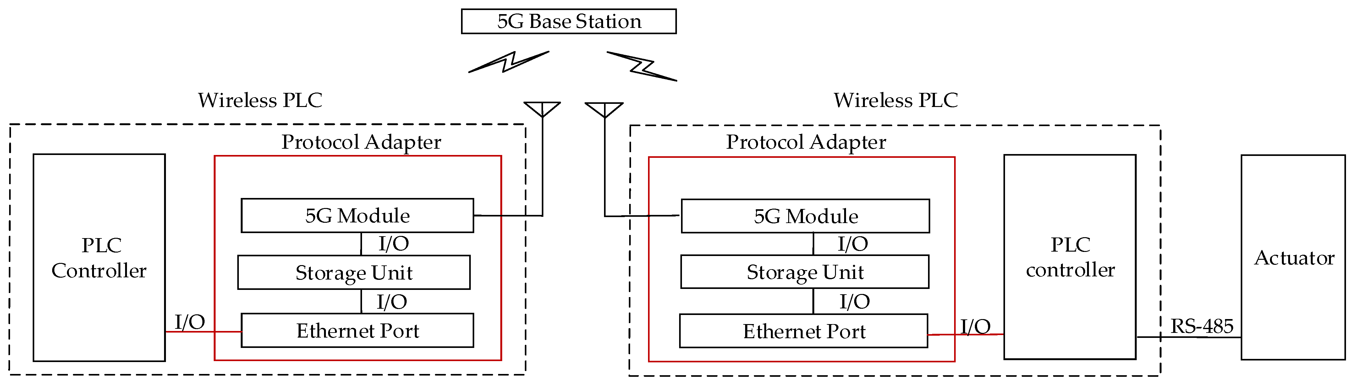
5.1. Hardware Architecture
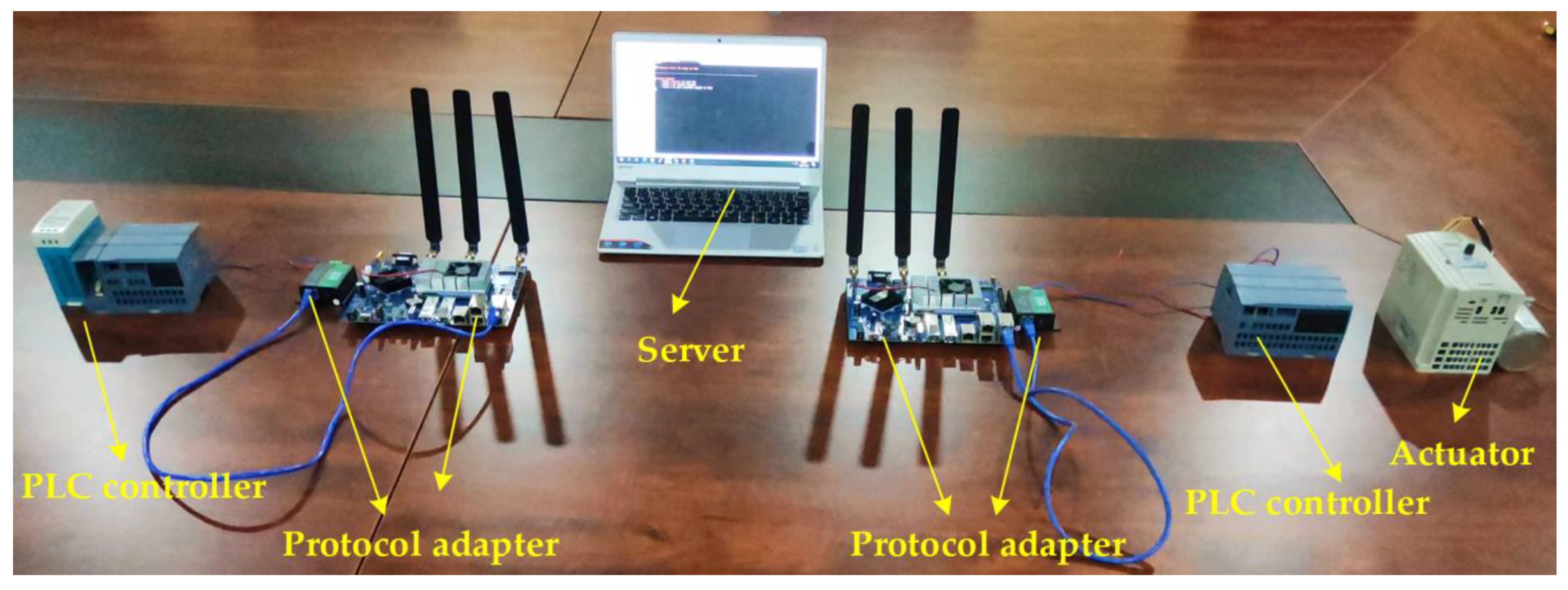
5.1.1. Prototyping for Modbus RTU
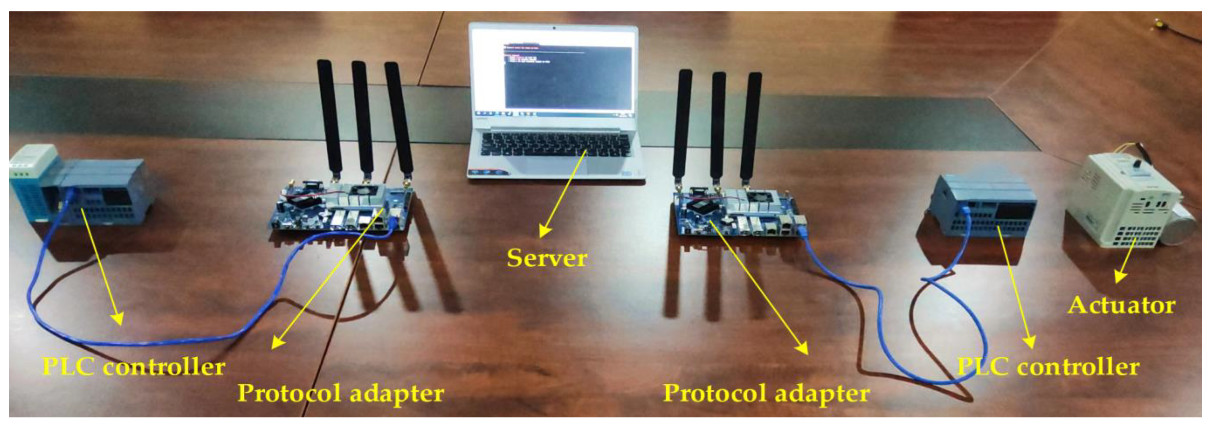
5.1.2. Prototyping for Modbus TCP
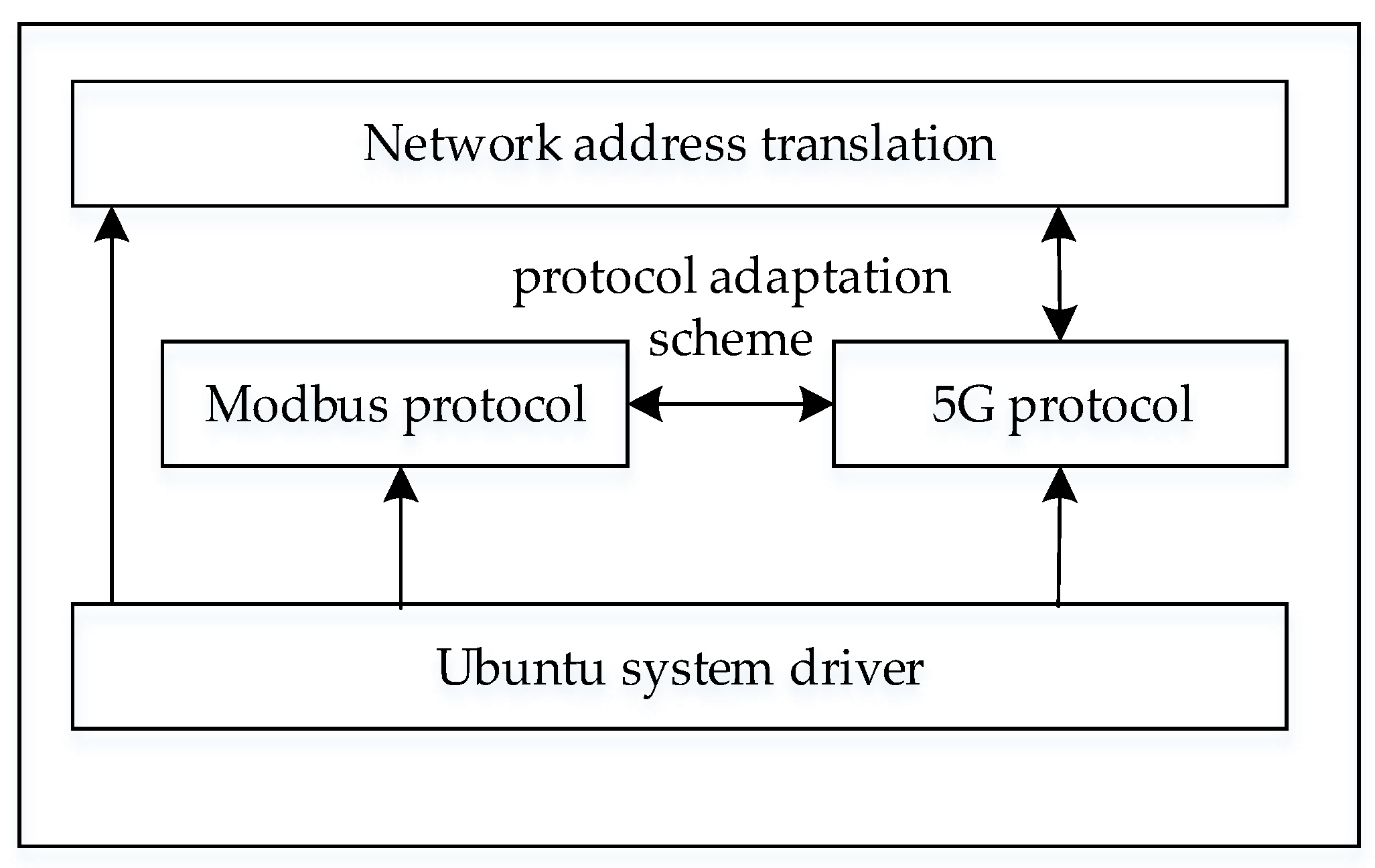
5.2. Software Design
- (1)
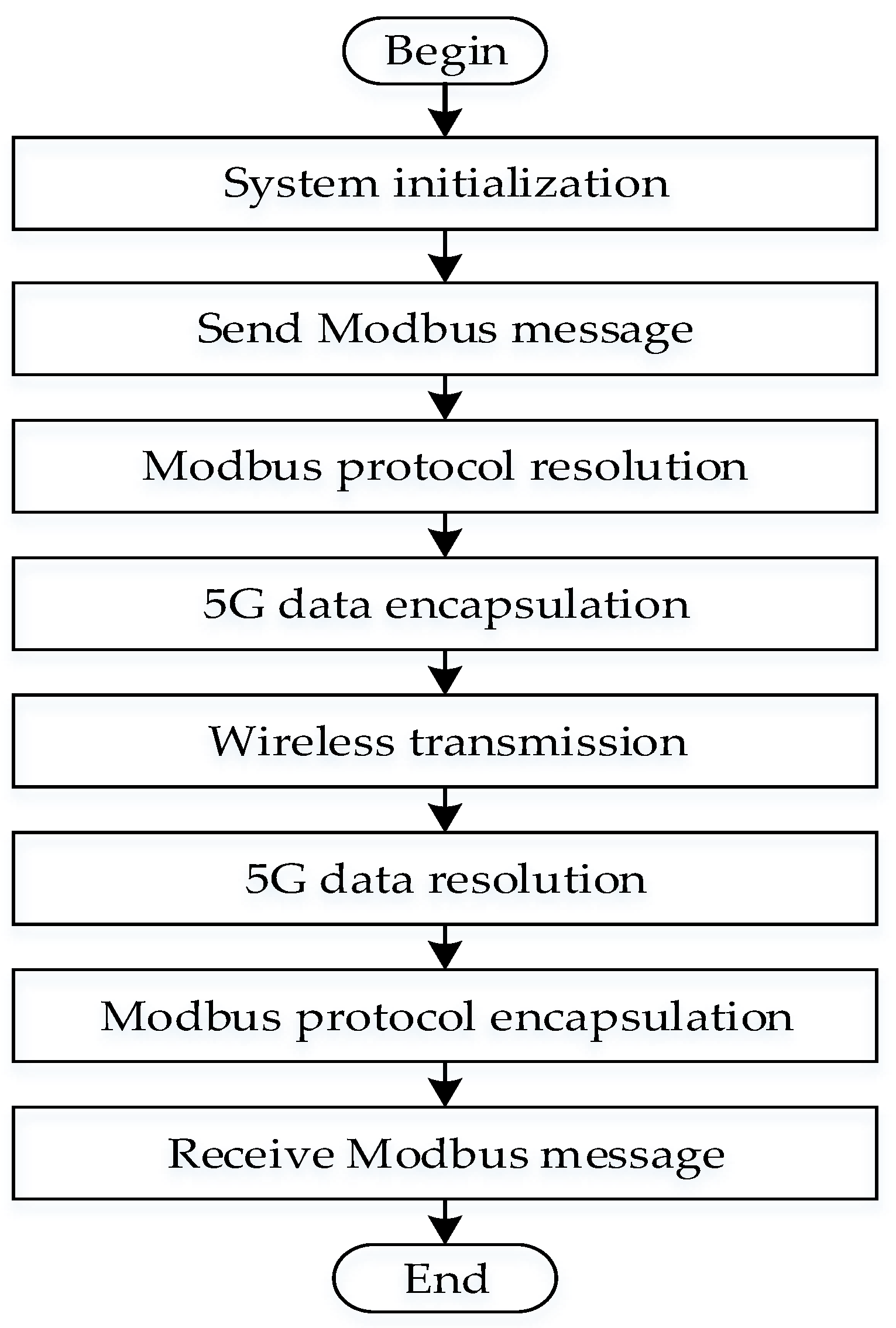
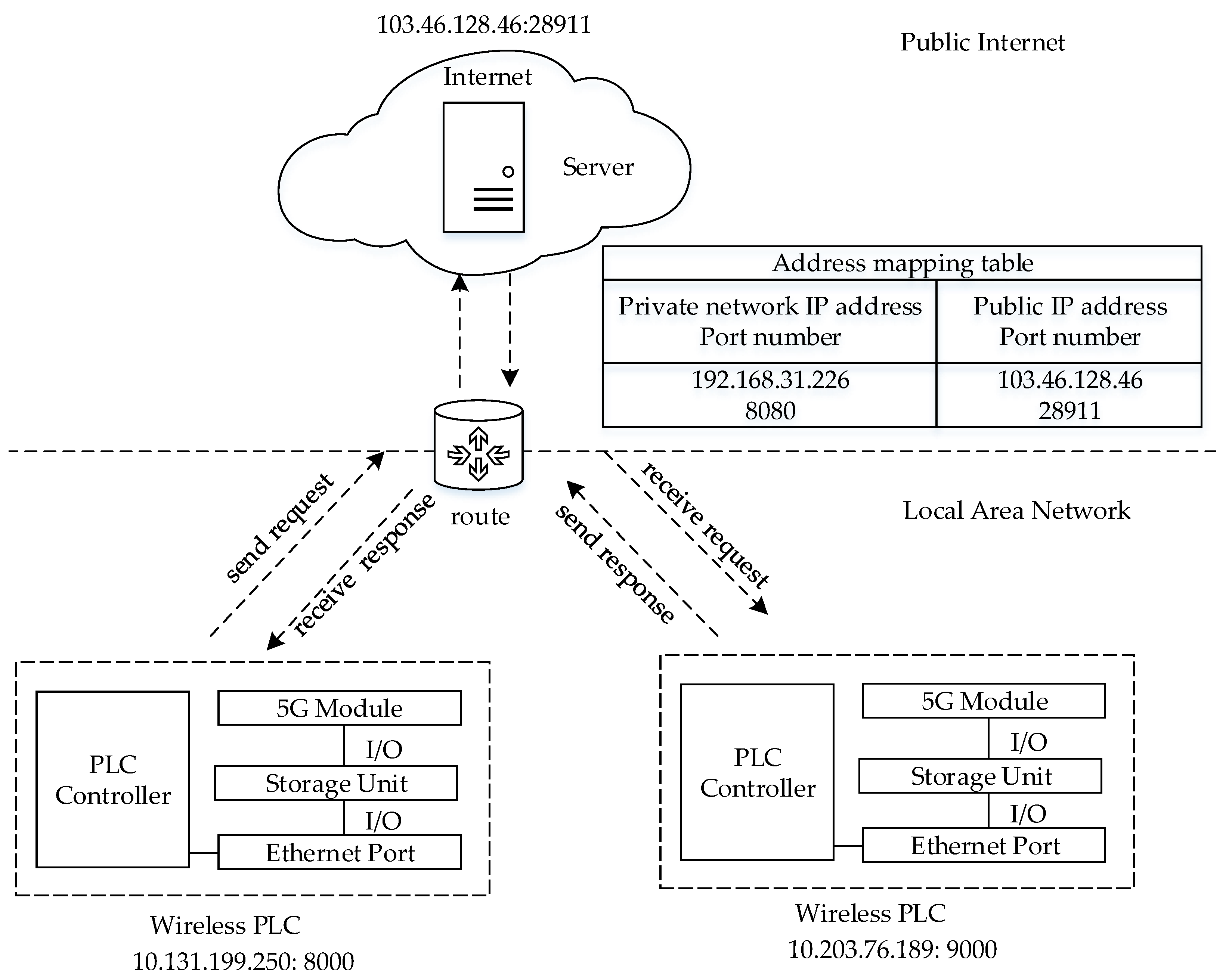
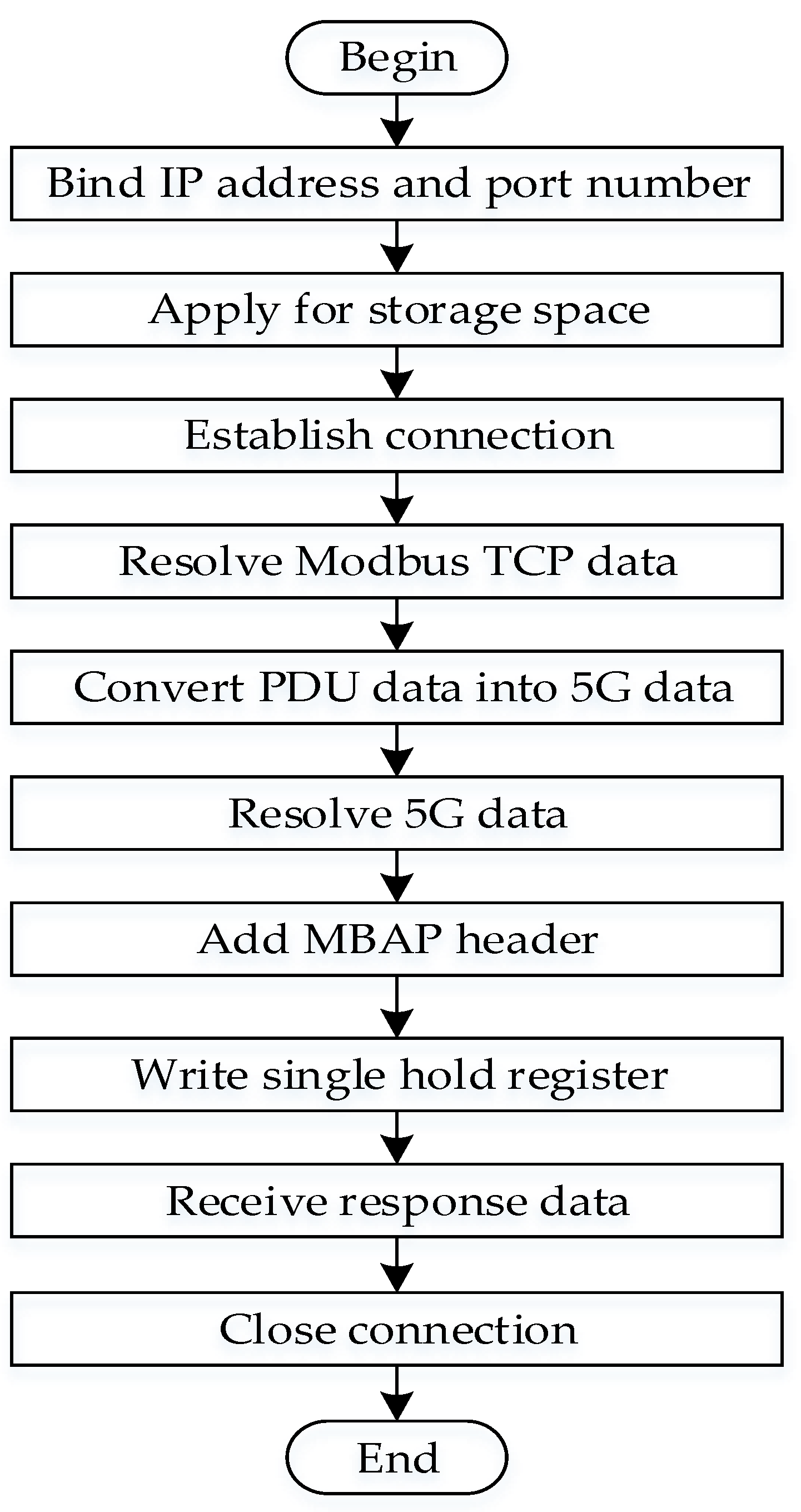
- Modbus TCP data. The first step is that we use the bind function to make the slave protocol adapter bind the local IP address and port number and the master protocol adapter bind the IP address and port number of the slave PLC controller. In the second step, we use the address mapping function to apply for memory to store register values. In the third step, we use the monitor function to make the slave protocol adapter wait for the connection of the master PLC controller and use the connection function to establish the connection of the master protocol adapter and the slave PLC controller. Afterward, we use the analysis function to resolve the Modbus TCP data and store the PDU data into a storage unit. The next step is to convert the Modbus PDU data into the 5G data through 5G modules. Then, we resolve the 5G data with analysis function. Next, we add the MBAP field to the Modbus PDU data and use the register write function to store data into the hold register of the PLC controller by the master protocol adapter. Figure 14 illustrates the implementation process of the Modbus TCP software.
- (2)
- Modbus RTU data; the protocol adapter is connected to the PLC controller through the Ethernet conversion module. Therefore, we use the socket form to realize data reception, data resolution, data storage, data conversion, and data transmission.
6. Experimental Evaluation
6.1. Experiment Setup
6.2. Result Analysis
7. Conclusions
Author Contributions
Funding
Data Availability Statement
Conflicts of Interest
Abbreviations
| 3GPP | 3th Generation Partnership Project |
| 5G-ACIA | 5G Alliance for Connected Industries and Automation |
| ADU | Application Data Unit |
| FSoE | FailSafe Over EtherCAT |
| ICNs | Industrial Control Networks |
| IWN | Industrial Wireless Network |
| ITU | International Telecommunication Union |
| MBAP | Modbus Application Protocol |
| MAC | Media Access Control |
| NR | New Radio |
| NSA | Non-Standalone |
| PLC | Programmable Logic Controller |
| PDU | Protocol Data Unit |
| PDCP | Packet Data Convergence Protocol |
| PHY | Physical Layer |
| QoS | Quality of Service |
| RTU | Remote Terminal Unit |
| RLC | Radio Link Control |
| SDAP | Service Data Adaption Protocol |
| SoC | System on Chip |
| SA | Standalone |
| TCP | Transmission Control Protocol |
| URLLC | Ultra-Reliable and Low-Latency Communication |
References
- Diao, Z.; Sun, F. Application of Internet of Things in Smart Factories under the Background of Industry 4.0 and 5G Communication Technology. Math. Probl. Eng. 2022, 2022, 4417620. [Google Scholar] [CrossRef]
- Yu, H.; Zeng, P.; Xu, C. Industrial Wireless Control Networks: From WIA to the Future. Engineering 2022, 8, 18–24. [Google Scholar] [CrossRef]
- Müller, T.; Doran, H.D. Protecting PROFINET cyclic real-time traffic: A performance evaluation and verification platform. In Proceedings of the 2018 14th IEEE International Workshop on Factory Communication Systems (WFCS), Imperia, Italy, 13–15 June 2018; pp. 1–4. [Google Scholar]
- Au, E. A Short Update on 3GPP Release 16 and Release 17 [Standards]. IEEE Veh. Technol. Mag. 2020, 15, 160. [Google Scholar] [CrossRef]
- Xu, C.; Zeng, P.; Yu, H.; Jin, X.; Xia, C. WIA-NR: Ultra-reliable low-latency communication for industrial wireless control networks over unlicensed bands. IEEE Netw. 2021, 35, 258–265. [Google Scholar] [CrossRef]
- Jaloudi, S. Communication protocols of an industrial Internet of things environment: A comparative study. Future Internet 2019, 11, 66. [Google Scholar] [CrossRef]
- González, I.; Calderón, A.J.; Portalo, J.M. Innovative multi-layered architecture for heterogeneous automation and monitoring systems: Application case of a photovoltaic smart microgrid. Sustainability 2021, 13, 2234. [Google Scholar] [CrossRef]
- Brito, I.B.; Jr, R.T. Development of an open-source testbed based on the Modbus protocol for cybersecurity analysis of nuclear power plants. Appl. Sci. 2022, 12, 7942. [Google Scholar] [CrossRef]
- Wei, M.; Li, C.; Li, C. An IPv6 Internet Accessing Architecture and Approach for Industrial Wireless Network. In Proceedings of the 2020 14th International Conference on Ubiquitous Information Management and Communication (IMCOM), Taichung, Taiwan, 3–5 January 2020; pp. 1–6. [Google Scholar]
- Gil, S.; Zapata-Madrigal, G.D.; García-Sierra, R.; Cruz Salazar, L.A. Converging IoT protocols for the data integration of automation systems in the electrical industry. J. Electr. Syst. Inf. Technol. 2022, 9, 1. [Google Scholar] [CrossRef]
- Kulik, V.; Kirichek, R. The Heterogeneous Gateways in the Industrial Internet of Things. In Proceedings of the 2018 10th International Congress on Ultra Modern Telecommunications and Control Systems and Workshops (ICUMT), Moscow, Russia, 5–9 November 2018; pp. 1–5. [Google Scholar]
- Shi, H.; Niu, L.; Sun, J. Construction of Industrial Internet of Things Based on MQTT and OPC UA Protocols. In Proceedings of the 2020 IEEE International Conference on Artificial Intelligence and Computer Applications (ICAICA), Dalian, China, 27–29 June 2020; pp. 1263–1267. [Google Scholar]
- Silva, C.R.M.; Silva, F.A.C.M. An IoT Gateway for Modbus and MQTT Integration. In Proceedings of the 2019 SBMO/IEEE MTT-S International Microwave and Optoelectronics Conference (IMOC), Aveiro, Portugal, 10–14 November 2019; pp. 1–3. [Google Scholar]
- Botero, J.G.Z.; Cuartas, J.A.H.; Garces, S.I.S. Communication Profibus-ZigBee using low cost gateway. In Proceedings of the 2015 IEEE 20th Conference on Emerging Technologies & Factory Automation (ETFA), Luxembourg, 8–11 September 2015; pp. 1–4. [Google Scholar]
- Ye, Y.t.; Lei, H.d. Wireless industrial communication system based on Profibus-DP and ZigBee. In Proceedings of the 2016 11th International Conference on Computer Science & Education (ICCSE), Nagoya, Japan, 23–25 August 2016; pp. 666–669. [Google Scholar]
- Zhou, Y.; Xiao, W.; Liu, M.; Li, X. Design of the embedded gateway for 4G and PROFIBUS-DP based on FPGA. In Proceedings of the 2017 3rd IEEE International Conference on Computer and Communications (ICCC), Chengdu, China, 13–16 December 2017; pp. 748–752. [Google Scholar]
- Wu, X.; Xie, L. On the Wireless Extension of EtherCAT Networks. In Proceedings of the 2017 IEEE 42nd Conference on Local Computer Networks (LCN), Singapore, 9–12 October 2017; pp. 235–238. [Google Scholar]
- Morato, A.; Vitturi, S.; Cenedese, A.; Fadel, G.; Tramarin, F. The Fail Safe over EtherCAT (FSoE) protocol implemented on the IEEE 802.11 WLAN. In Proceedings of the 2019 24th IEEE International Conference on Emerging Technologies and Factory Automation (ETFA), Zaragoza, Spain, 10–13 September 2019; pp. 1163–1170. [Google Scholar]
- Wu, X.; Xie, L. On the Wireless Extension of PROFINET Networks. In Proceedings of the 2019 IEEE VTS Asia Pacific Wireless Communications Symposium (APWCS), Singapore, 28–30 August 2019; pp. 1–5. [Google Scholar]
- Trancă, D.C.; Pălăcean, A.V.; Mihu, A.C.; Rosner, D. ZigBee based wireless modbus aggregator for intelligent industrial facilities. In Proceedings of the 2017 25th Telecommunication Forum (TELFOR), Belgrade, Serbia, 21–22 November2017; pp. 1–4. [Google Scholar]
- Yang, M.; Lim, S.; Oh, S.M.; Shin, J. An Uplink Transmission Scheme for TSN Service in 5G Industrial IoT. In Proceedings of the 2020 International Conference on Information and Communication Technology Convergence (ICTC), Jeju-do, Republic of Korea, 21–23 October 2020; pp. 902–904. [Google Scholar]
- Nikhileswar, K.; Prabhu, K.; Cavalcanti, D.; Regev, A. Time-Sensitive Networking Over 5G for Industrial Control Systems. In Proceedings of the 2022 IEEE 27th International Conference on Emerging Technologies and Factory Automation (ETFA), Stuttgart, Germany, 6–9 September 2022; pp. 1–8. [Google Scholar]
- Satka, Z.; Pantzar, D.; Magnusson, A.; Ashjaei, M.; Fotouhi, H.; Sjödin, M.; Daneshtalab, M.; Mubeen, S. Developing a Translation Technique for Converged TSN-5G Communication. In Proceedings of the 2022 IEEE 18th International Conference on Factory Communication Systems (WFCS), Pavia, Italy, 27–29 April 2022; pp. 1–8. [Google Scholar]
- Jiang, X.; Pang, Z.; Zhan, M.; Dzung, D.; Luvisotto, M.; Fischione, C. Packet Detection by a Single OFDM Symbol in URLLC for Critical Industrial Control: A Realistic Study. IEEE J. Sel. Areas Commun. 2019, 37, 933–946. [Google Scholar] [CrossRef]
- Khoshnevisan, M.; Joseph, V.; Gupta, P.; Meshkati, F.; Prakash, R.; Tinnakornsrisuphap, P. 5G Industrial Networks With CoMP for URLLC and Time Sensitive Network Architecture. IEEE J. Sel. Areas Commun. 2019, 37, 947–959. [Google Scholar] [CrossRef]
- Ghassemian, M.; Muschamp, P.; Warren, D. Experience Building a 5G Testbed Platform. In Proceedings of the 2020 IEEE 3rd 5G World Forum (5GWF), Bangalore, India, 10–12 September 2020; pp. 473–478. [Google Scholar]
- Ansari, J.; Andersson, C.; de Bruin, P.; Farkas, J.; Grosjean, L.; Sachs, J.; Torsner, J.; Varga, B.; Harutyunyan, D.; König, N.; et al. Performance of 5G Trials for Industrial Automation. Electronics 2022, 11, 412. [Google Scholar] [CrossRef]
- Raditya, M.; Darwito, P.A.; Fahmi, Z.N.; Cikadiarta, A.; Putra, A.P.; Wicaksana, S.S. Multiple Linear Guide Actuator (LGA) Controller Based on Modbus RTU. In Proceedings of the 2021 3rd International Conference on Research and Academic Community Services (ICRACOS), Surabaya, Indonesia, 9–10 October 2021; pp. 209–213. [Google Scholar]
- Dawid, K.; Helka-Liina, M. Network Architecture and NR Radio Protocols. In 5G New Radio: A Beam-based Air Interface; Wiley: Hoboken, NJ, USA, 2020; pp. 25–93. [Google Scholar]
- Le, T.K.; Salim, U.; Kaltenberger, F. An Overview of Physical Layer Design for Ultra-Reliable Low-Latency Communications in 3GPP Releases 15, 16, and 17. IEEE Access 2021, 9, 433–444. [Google Scholar] [CrossRef]
- Rinaldi, F.; Raschellà, A.; Pizzi, S. 5G NR system design: A concise survey of key features and capabilities. Wirel. Netw. 2021, 27, 5173–5188. [Google Scholar] [CrossRef]
- Mwakwata, C.B.; Malik, H.; Mahtab Alam, M.; Le Moullec, Y.; Parand, S.; Mumtaz, S. Narrowband Internet of Things (NB-IoT): From Physical (PHY) and Media Access Control (MAC) Layers Perspectives. Sensors 2019, 19, 2613. [Google Scholar] [CrossRef] [PubMed]


Disclaimer/Publisher’s Note: The statements, opinions and data contained in all publications are solely those of the individual author(s) and contributor(s) and not of MDPI and/or the editor(s). MDPI and/or the editor(s) disclaim responsibility for any injury to people or property resulting from any ideas, methods, instructions or products referred to in the content. |
© 2023 by the authors. Licensee MDPI, Basel, Switzerland. This article is an open access article distributed under the terms and conditions of the Creative Commons Attribution (CC BY) license (https://creativecommons.org/licenses/by/4.0/).
Share and Cite
Xu, C.; Du, X.; Li, X.; Tu, Y.; Li, L.; Jin, X.; Xia, C. 5G-Based Industrial Wireless Controller: Protocol Adaptation, Prototype Development, and Experimental Evaluation. Actuators 2023, 12, 49. https://doi.org/10.3390/act12020049
Xu C, Du X, Li X, Tu Y, Li L, Jin X, Xia C. 5G-Based Industrial Wireless Controller: Protocol Adaptation, Prototype Development, and Experimental Evaluation. Actuators. 2023; 12(2):49. https://doi.org/10.3390/act12020049
Chicago/Turabian StyleXu, Chi, Xinyi Du, Xinchun Li, Yachun Tu, Lin Li, Xi Jin, and Changqing Xia. 2023. "5G-Based Industrial Wireless Controller: Protocol Adaptation, Prototype Development, and Experimental Evaluation" Actuators 12, no. 2: 49. https://doi.org/10.3390/act12020049
APA StyleXu, C., Du, X., Li, X., Tu, Y., Li, L., Jin, X., & Xia, C. (2023). 5G-Based Industrial Wireless Controller: Protocol Adaptation, Prototype Development, and Experimental Evaluation. Actuators, 12(2), 49. https://doi.org/10.3390/act12020049