1. Introduction
Permanent magnet synchronous motors have been used in various applications for centuries due to their many advantages, such as high efficiency, high torque-to-current and torque-to-volume ratios, compact structure, and fast dynamic response [
1,
2,
3,
4,
5,
6,
7,
8,
9,
10,
11].
In particular, due to the global movement to reduce greenhouse gases, electrification is rapidly occurring in the automotive area. As a result, the adoption of electric motors to replace internal combustion engines and hydraulics, which are existing power sources, is increasing. Additionally, high-output and compact-size electric motors are required to improve vehicle efficiency [
2,
7,
10,
12].
Moreover, as suggested by Moore’s Law, computer performance has improved dramatically, and as a result, the calculation speed of FEM S/W required for electric motor design and analysis has also improved dramatically. Therefore, multiple design models can be calculated more quickly and various system phenomena can be solved using software such as finite element analysis tools [
13]. However, many commercial tools are expensive to purchase and maintain, making owning and maintaining many licenses burdensome unless the company or research institute is well funded. Therefore, in most cases, it is difficult for motor design engineers to use commercial software simultaneously with limited licenses, so it is necessary to establish a way to operate it efficiently.
In the field, motor design engineers are frequently asked by their customers to design and quote for electric motors that meet the desired performance within a short period of time. In the case of an expert with enough experience or lots of evaluated data and design references, there may be no risk in responding to such requests. However, it would be challenging work under time constraints in most cases. In addition, price competition among motor manufacturers is intensifying due to the extension of electric motor adoption to many applications. Furthermore, the market price needs to decrease gradually, making it more difficult to make a profit. In this case, most motor manufacturers can convert existing electric motors into a platform to increase production and lower manufacturing costs. This method can significantly reduce new investments via the manufacture of key components, such as the rotor and stator core, using the same tooling used to produce conventional products, changing the stack lengths and windings in different ways to meet the required performance. Additionally, the development period can be shortened, minimizing the resources required for development.
Nevertheless, as mentioned earlier, it is often impossible to use expensive motor design S/W promptly to respond to the tight timescales given by customers for electric motor design.
Therefore, in this paper, an effective motor sizing method that can be used in the field is proposed to solve this problem. To this end, a reference model to be used as a platform design was selected first and the evaluation and analysis data were collected via FEM for this motor as the reference data.
Then, the relationship between the wire diameter, number of turns, and lamination length, which are the design variables used when determining motor size, was derived for the fundamental parameters of the motor, such as resistance (Rs), inductance (Ls), and back EMF constant (Ke).
In order to increase the accuracy of calculations, the torque under load, torque ripple, and demagnetization characteristics of permanent magnets, which are nonlinear characteristics that change with the increase in the ampere-turn condition, were databased within the sizing process template by performing FEM analysis on the reference model. This process only needs to be performed once for the reference model, as there is no need to analyze it using expensive FEM S/W every time motor sizing is needed in the future. In this way, using the results in the database of the preformed template and the relationship between the three design variables (wire diameter, number of turns, and stacking length) and the motor performance, the characteristics of the motor can be quickly calculated and specifications that meet the relevant requirements can be found effectively in seconds.
In summary, the sizing method proposed in this paper has the substantial advantage of enabling the rapid design of an electric motor that meets the relevant requirements, regardless of the designer’s experience and skill level, without using expensive S/W.
The motor sizing technique presented in this paper was first verified by comparing it with the FEM calculation results. Then, prototype samples were built and tested to verify the method’s effectiveness.
3. Sizing Theories and Procedure
3.1. Magnet Flux Loss
There are several magnetic materials used in the electrical motor. Among them, the NdFeB sintered magnet is suitable for high-power density and compact-size motors due to its excellent magnetic characteristics and is used in various applications. In addition, this magnet requires a coating treatment on the surface to prevent magnetic performance degradation due to damage such as cracks and corrosion, of which there are coating options of various materials and thicknesses, as shown in
Table 2.
According to the research in [
18], there is a difference in the magnetic performance of permanent magnets depending on the presence or absence of a coating, as shown in
Figure 3. This is because the proportion of raw materials in the magnet itself decreases depending on the coating thickness and the overall size of the magnet, as shown in
Figure 4. It would be expected that the thicker the coating, the greater the reduction in the active material at the expense of the thickness of the protective layer of the magnet. Additionally, it can be expected that the smaller the size of the magnet and the shorter the axial length, the greater the magnetic flux loss will be. In the case of motors with high output power, such as vehicle traction motors, the ratio of the coating thickness to the magnet’s size is tiny, so this effect can be ignored. However, in the case of an electric power steering (EPS) motor that requires an output of around or less than 1 kW, the magnetic flux loss component due to the thickness of the magnet coating can act as the root cause of errors between the design value and the actual measurement.
Therefore, it is necessary to consider the loss component of the magnetic flux due to the coating thickness of the magnet in the motor design process, especially for low-power electrical motors. In this study, a method for considering the magnetic flux loss was applied by comparing the volume of the magnet’s raw material to the total volume of the selected magnet, as shown in Equation (
1), to reduce the error between the motor sizing results and the actual test value.
In the equation, is the magnet flux loss, is the raw material volume of the magnet, and is the overall magnet volume, including the coating.
In addition, to improve the productivity of permanent magnets, material loss due to the round shape applied to each corner was considered to be 4% of this design, as shown in Equation (
2).
In the equation, is the magnet flux loss, including the material loss due to the round edge shape.
Since the two-dimensional shape and dimensions of the reference model have already been designed, the two-dimensional area of the magnet is determined based on the designed value, which is verified using the actual measurement. When calculating the motor sizing, once the coating material and thickness are determined, the area of the magnet’s raw material is calculated. By assuming the axial length, the magnetic flux loss for a magnet of the desired length can be calculated using Equation (
2).
Figure 5 shows the result of calculating the magnetic loss of the magnet for each coating according to the stack length using the reference model and Equation (
2). Here, the coating thickness was considered with the average value in
Table 2.
According to these results, it can be seen that the magnetic loss tends to increase as the lamination length decreases and the coating thickness increases, and this was reflected in the sizing process to reduce errors in the test results.
3.2. Back EMF Constant ()
The back electromotive force (back EMF) is an essential indicator of an electric motor’s performance. It is calculated as the induced voltage generated per unit speed, as shown in Equation (
3), and is determined by many design parameters, as shown in Equation (
4) [
1].
In the equation,
E is the back EMF voltage,
is the back EMF constant, and
is the angular velocity.
In the equation, P is the pole number, Z denotes the total series turns, is the total magnetic flux per pole, B is the magnetic flux density, D is the diameter of the air gap, is the active stack length, and a is the number of parallel conductors.
According to Equation (
4), the back electromotive force is proportional to the number of turns and stack length, which are variables to be used during motor sizing. Therefore,
can be calculated easily from the design variables and the magnetic flux loss as defined previously for the reference motor using Equation (
5):
where
,
,
, and
denote the back EMF constant, number of turns, stack length, and magnetic flux loss of the reference model, respectively.
,
,
, and
denote the back EMF, number of turns, stack length, and magnetic flux loss of the modification model to be designed, respectively.
The calculation results for
obtained by combining the stack length and the number of turns using Equation (
5) are shown in
Figure 6. This sizing study considered the stack from 10 mm to 90 mm and the winding from 10 to 40 turns.
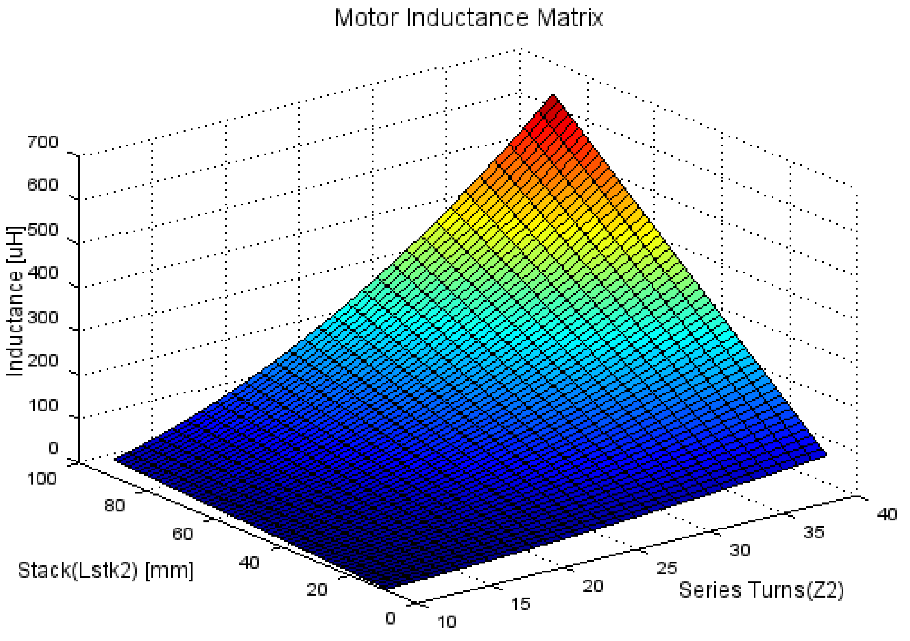
3.3. Motor Inductance
The motor inductance is a parameter affected by many design variables, such as the intensity of the magnetic flux, number of turns, and length of stacking, as shown in Equation (
6) [
3].
where
L is the motor inductance,
is the total magnetic flux linkage,
i is the current,
N is the total series turns,
is the magnetic flux in the coil,
is the magnetomotive force,
is the permeance,
A is the cross-sectional area, and
l is the length of the magnetic circuit.
In the same two-dimensional magnetic circuit, the cross-sectional area
A is proportional to the stack length
. Therefore, the inductance would be proportional to the stack length and the square of the winding turns. As the ampere-turn condition increases, the inductance may differ from the result obtained using the above Equation (
6) due to magnetic saturation in the magnetic circuit. However, to develop an efficient and rapid calculation method in this study, the design was assumed to be under ampere-turn conditions, where magnetic saturation does not occur and the inductance was calculated using the equation of the linear relationship. In this way, the inductance for all combinations of turns and stack lengths can be calculated using Equation (
7), as shown in
Figure 7.
where
and
denote the inductance of the reference and the modification model to be designed, respectively.
3.4. Current Density
The current density of a motor is related to the coil’s durability and the motor’s temperature characteristics. The lower the current density, the better the motor characteristics, but the size increases, so selecting an appropriate current density level is necessary.
Most electric power steering motors have a completely sealed structure, and due to the instantaneous operation behavior, they use a cooling method via natural convection without an additional cooling device. Therefore, selecting a current density level in the range 15 to 25 Arms/mm2 at the maximum current condition is generally appropriate for this design, which operates in an instantaneous condition.
The coil diameter of the motor to be designed can be determined using the input current and the number of parallel circuits, as shown in Equations (
8) and (
9) below.
Here,
is the current density,
is the input current,
a is the parallel circuit, and
is the coil diameter.
Figure 8 below shows the current density calculation result according to the coil diameter with two strands at a 100 A input current condition.
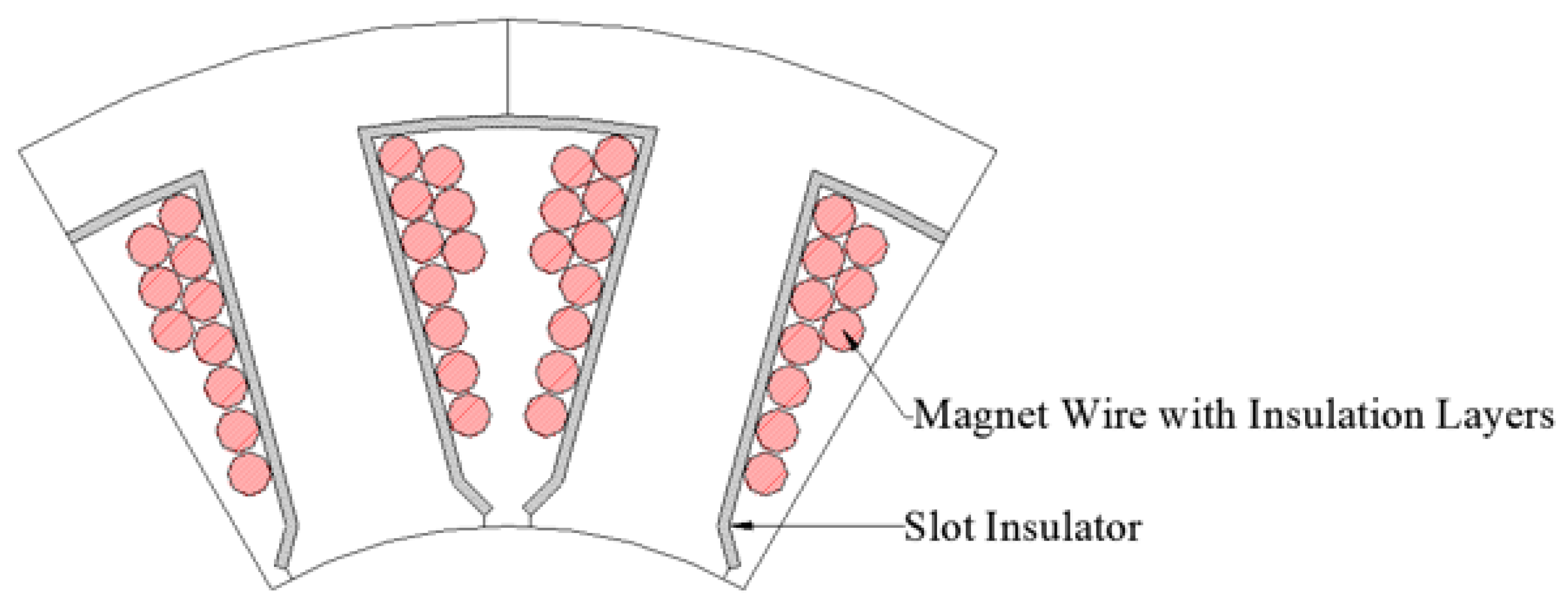
3.5. Winding Feasibility Study
Since the two-dimensional shape of the reference model has already been defined, it is possible to predict the maximum number of turns that can be wound using the actual drawing, as shown in
Figure 9. It is advisable to consider the outer coil diameter, including the insulation coating layers and slot insulator thickness in the slots, to minimize differences from the actual product, as shown in the figure.
In this way, it is possible to create a winding capability database of the reference model for a wide range of coil diameters, as shown in
Figure 10. The results show the winding feasibility from 1.0 mm to 3.0 mm of the diameter as the condition of the same slot area in this reference model.
3.6. Resistance
The general formula for electrical resistance is as follows.
where
R is the motor resistance,
is the resistivity of the coil,
is the total length of the coil, and
is the cross-sectional area of the coil.
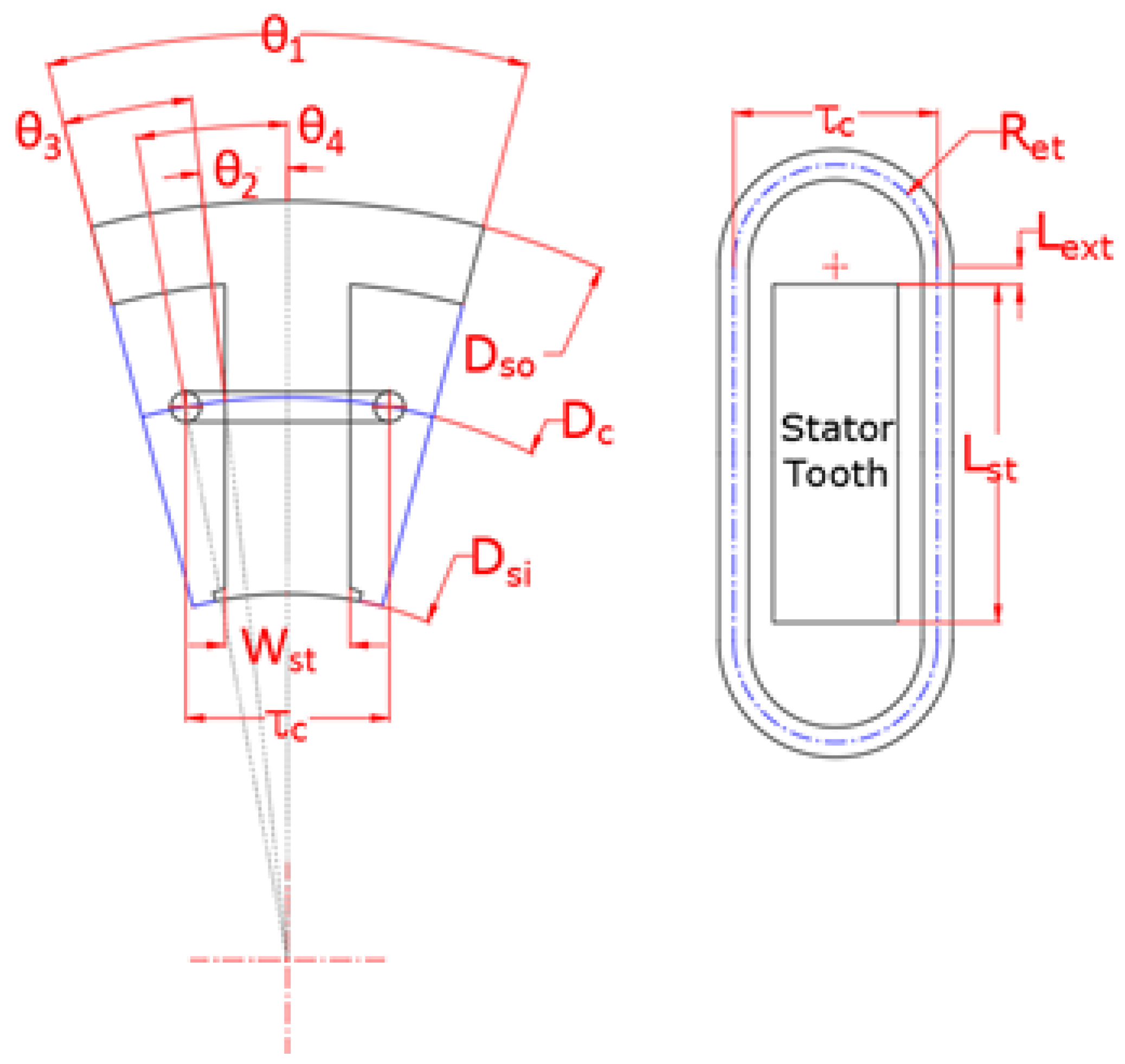
The length of the conductor can be calculated using Equation (
11) to Equation (
17) and the parameters defined in
Figure 11.
In the equation,
and
are the radius and diameter center dimension of the coil wound on the stator, respectively, and
and
are the outer and inner diameters of the stator core, respectively, as defined in
Figure 11.
All the parameters defined in the figure can be calculated as follows.
where
Q is the number of stator slots and
is the one slot angle.
where
is the tooth width of the stator core and
is the half-slot coil pitch angle.
where
is the one coil pitch.
In addition,
, defined in
Figure 11, is a length depending on the thickness of the slot insulator. Assuming that the coil at the end turn area is formed in a semicircle as large as the coil pitch dimension, the coil length per turn
and resistance per turn
are as follows.
Using the given number of turns
and parallel circuits
a, the phase resistance can be calculated as shown in Equation (
19). Also, using copper’s resistance temperature coefficient
, changes in the resistance value at a sizing temperature condition (t degrees) can be calculated using Equation (
20).
In the equation, is the temperature coefficient of copper calculated as 3.93 × 10 m; t is the sizing temperature given by the requirement; and is room temperature.
In this sizing technique, only the coil diameter, number of turns, and lamination length are design variables, and by using Equations (
17)–(
20), the resistance values for all cases under different conditions can be calculated.
3.7. Torque Constant Saturation, Torque Ripple, and Demagnetization
The torque constant () is the torque per unit current and, like the back electromotive force constant (), is a parameter that represents the unique characteristics of the electric motor. Kt decreases due to the magnetic saturation effect of the magnetic circuit in the motor as the current increases. Due to this magnetic saturation phenomenon, the term Kt saturation is used to refer to the change in .
In a sinusoidal drive three-phase motor, the back EMF constant (
) and torque constant (
) have the following specific relationship [
1].
Here, the unit of the back EMF constant () is Vll-pk/rad/s and the torque constant () is Nm/Apk.
The relationship in Equation (
21) shows the ideal condition established with no effect from magnetic saturation or temperature. From this relationship, the ratio of the Kt value between the model at no load and at a specific load current condition can be defined as in Equation (
22) below.
where
is the saturation ratio of the torque constant compared between a torque constant
at a specific current condition and the torque constant
without a current condition, as defined from Equation (
21).
When the saturation of the torque constant increases, the torque value generated from the motor decreases compared to the reference model and torque ripple tends to increase.
These non-linear characteristics must be calculated in advance for each ampere-turn condition using the reference model via FEM analysis S/W, which allows for precise calculation. In this way, when an urgent sizing request is made by a customer at any time, the results of the non-linear characteristics for all ampere turns that have been reviewed in advance can be used as a lookup table to increase prediction precision and enable rapid response without performing FEM S/W analysis.
The demagnetization of PMSM is another characteristic showing a nonlinear trend due to the demagnetization curve having a knee point at a particular coercivity condition.
In this study, the nonlinear analysis was performed from 50 to 5000 ampere turns and the non-linearity data on Kt, torque ripple, and demagnetization were secured in advance to build a database as shown in
Figure 12 and
Figure 13.
3.8. Torque–Speed Performance
The design of an electric motor involves finding parameters such as magnetic flux, inductance, and resistance that satisfy the voltage equation and torque equation expressed in Equations (
23) and (
24) [
19,
20].
In the equation, T is torque; is the pole pair number of the magnet; is magnetic flux linkage; is the current angle; and are the d- and q-axis inductance, respectively; and are the d- and q-axis current, respectively; is the input current; is voltage; and is the angular velocity.
Equation (
23) will be more straightforward because of the same
and
in SPMSM.
The torque–speed characteristic is one of the final performances determined by fundamental parameters such as the resistance, inductance, and magnetic flux linkage of an electric motor, and there can be countless combinations of these parameters to satisfy the performance. Among these results, the optimal decision as an electric motor designer is to select the smallest stack length electric motor in consideration of the price.
Using the three parameters of back EMF constant (Ke), resistance, and inductance, which are the fundamental parameters of the motor described previously, the required torque and speed characteristics can be calculated within the given constraints such as input voltage and current limits.
The magnetic flux linkage
can be obtained using Equations (
25) and (
26) [
1,
3,
4].
where
is the back EMF without load current,
is the calculated value from Equation (
5), and
is the mechanical rotation velocity. It has a 1/pole pair relationship with the electrical rotation velocity
.
In Equations (
23) and (
25), the pole pair (
) has been defined already from the reference design. The voltage (
) can be limited as shown in Equation (
27) by the phase resistance (
), calculated in
Section 3.5, and the given input current (
), from the requirement.
Moreover, the inductance ( and ) and the magnetic flux linkage () were found in the previous procedures.
Therefore, the torque and the rotation velocity in Equations (
23) and (
25) can be calculated by chaining the current angle (
).
3.9. Sizing Procedure
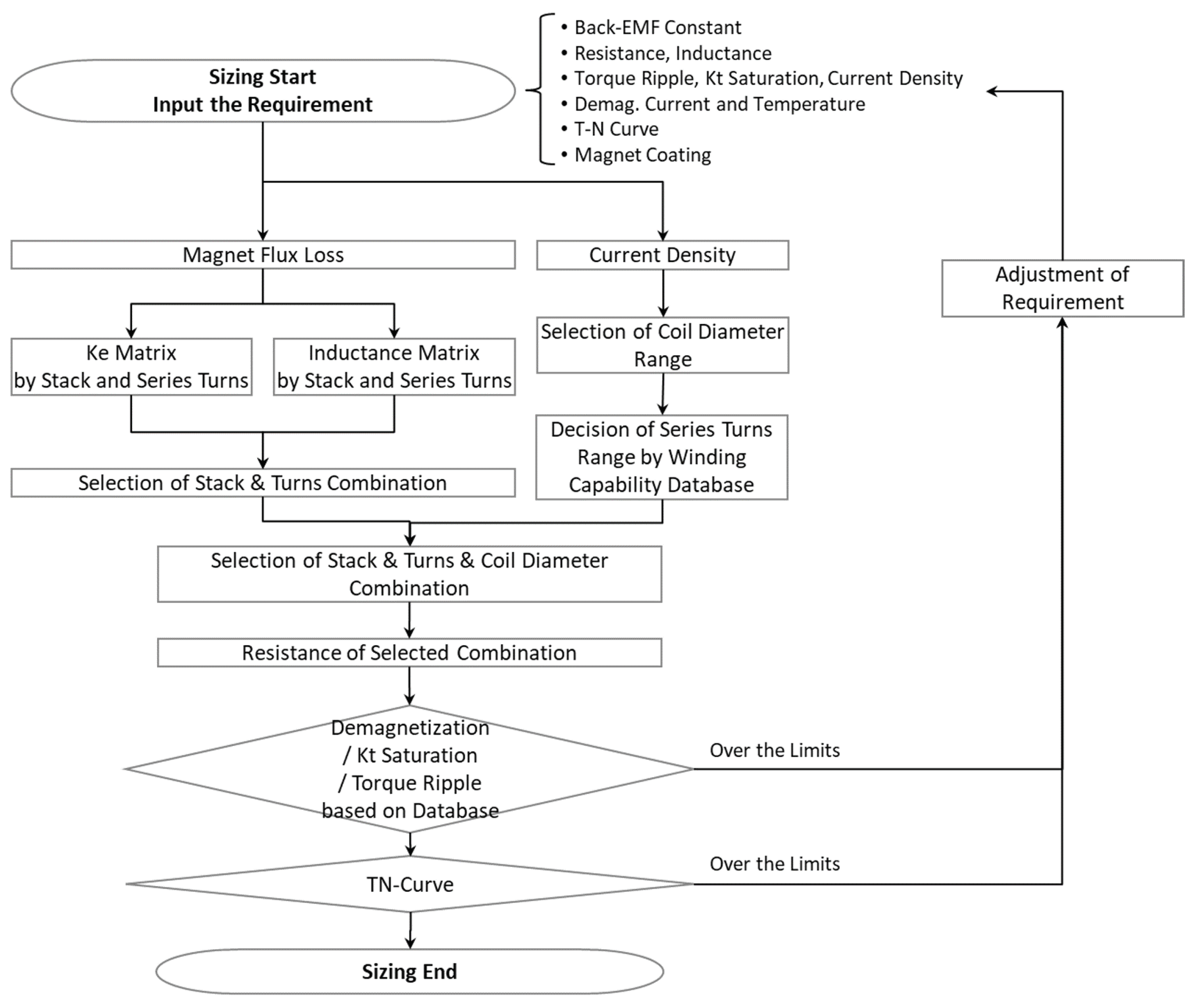
The procedure for the sizing technique proposed in this paper is shown in
Figure 14. First, it is necessary to define the target values for the performance parameters, such as
, resistance, inductance, etc., of the electric motor to be designed. Then, we determine the magnet coating specifications to be applied to the motor, calculate the magnetic flux loss components of the magnets as described in
Section 3.1, and calculate the
Ke matrix and inductance matrix for the stack length and series turns, respectively, based on the reference model as explained in
Section 3.2 to
Section 3.3. Next, the stack length for each turn that satisfies the requirements is selected from the calculated
and inductance results.
The current density of the coil is calculated using the given current value and a coil diameter with a current density that meets the requirements is selected as described in
Section 3.4. The maximum number of turns is determined using the winding capability database of the base model, as explained in
Section 3.5.
The next step is to calculate resistance values based on
Section 3.6 for combinations of wire diameters, number of turns, and stack lengths that satisfy
, inductance, and current density. These combinations are checked using the database to see if nonlinear characteristics such as torque ripple and demagnetization are satisfied, as explained in
Section 3.7. The torque–speed (T–N) characteristic calculation is performed using the determined parameters if all conditions are satisfied. Otherwise, the requirements need to be adjusted as described in
Section 3.8.
The results can be checked at a glance as soon as the requirements are input because none of these processes require a separate nonlinear calculation process using FEM S/W or any additional calculation.
5. Conclusions
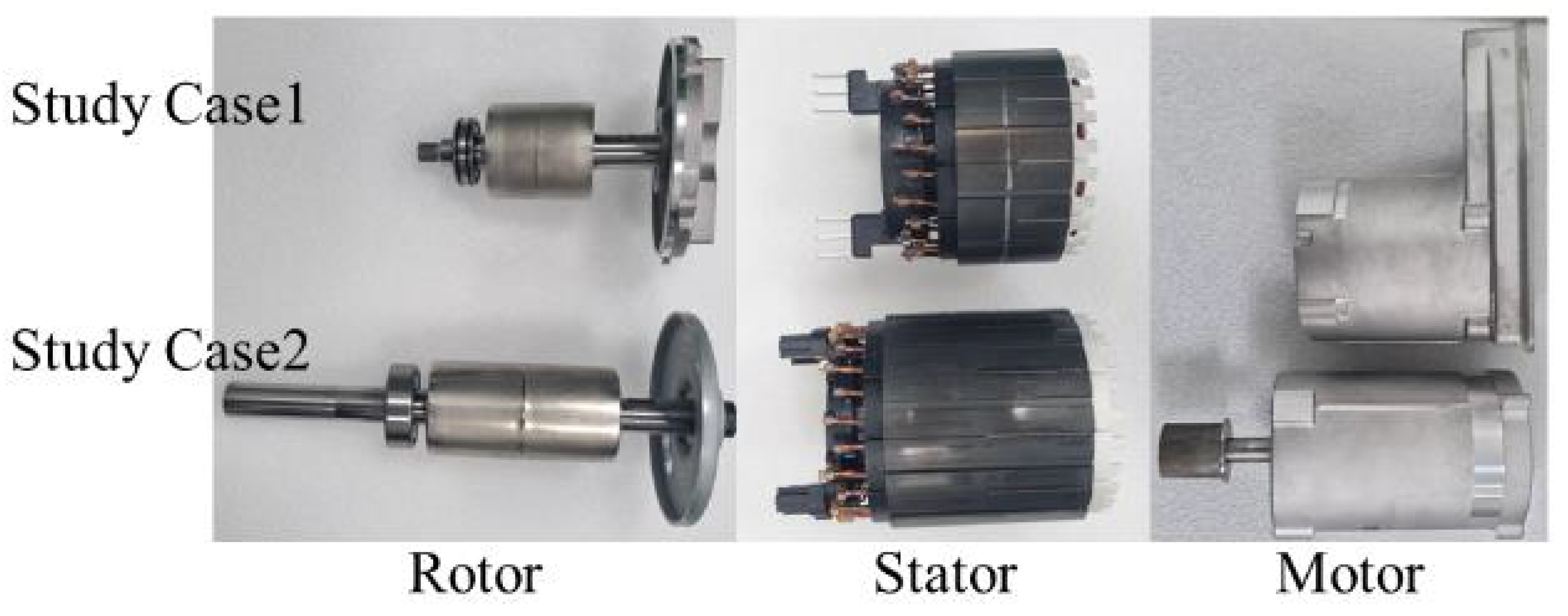
In this paper, we proposed a practical and rapid sizing method for existing platform motors that could reduce production costs using key components, such as the rotor core and stator core. The motor parameters to be designed are calculated using the equations and based on the parameters of the reference model. The magnetic flux loss due to the magnet coating is considered to increase the accuracy of the results. Nonlinear characteristics, such as torque ripple and demagnetization, are reflected by setting up a database via accurate FEM results in advance to enhance the fidelity of the results. Nonlinear calculation via FEM is required only once when setting up the database for the reference model. This method has been verified using two study case specifications, and the proposed sizing results compare well to the FEM and test results.
This method will help researchers create designs using existing products in a short time under the condition of no changes to the two-dimensional shape and material of the motor. The method does not need a certain level of experience for the motor designer and does not involve using expensive FEM S/W.
Moreover, it can be applied regardless of the type and configuration of the motor under the premise that only the stack length, number of turns, and coil diameter change from the reference model.
For future works, the model needs to be studied further to improve the calculation accuracy for non-linear parameters such as torque ripple, demagnetization, and inductance, which could be affected easily by magnetic saturation.


