Abstract
We propose to study the nonlinear stroke and lower-order modal interactions of a clamped–clamped shallow-arch flexible micro-electrode. The flexible electrode is electrically actuated through an in-plane parallel-plates field superimposed over out-of-plane electrostatic fringing fields. The in-plane electrostatic fields result from a difference of potential between the initially curved flexible electrode and a lower stationary parallel-grounded electrode. Moreover, the out-of-plane fringing fields are mainly due to the out-of-plane asymmetry of the flexible shallow arch and two respective surrounding stationary side electrodes (left and right). A nonlinear beam model is first introduced, consisting of a nonlinear partial differential equation governing the flexible shallow-arch in-plane deflection. Then, a resultant reduced-order model (ROM) is derived assuming a Galerkin modal decomposition with mode-shapes of a clamped–clamped beam as basis functions. The ROM coupled modal equations are numerically solved to obtain the static deflection. The results indicate the possibility of mono-stable and bi-stable structural behaviors for this particular device, depending on the flexible electrode’s initial rise and the size of its stationary side electrodes. The eigenvalue problem is also derived and examined to estimate the variation of the first three lower natural frequencies of the device when the microbeam is electrostatically actuated. The proposed micro-device is tunable with the possibility of pull-in-free states in addition to modal interactions through linear coupled mode veering and crossover processes. Remarkably, the veering zone between the first and third modes can be electrostatically adjusted and reach kHz for a particular set of design parameters.
1. Introduction
The Micro Electromechanical Systems (MEMS) industry has been acknowledged as one of the most auspicious technologies of the past century, primarily in developing both industrial and domestic products by combining silicon-based microstructures with micromachining technology [1]. Microbeams remain the principal building blocks for many MEMS-based microstructures. These were predominantly used as actuators [2] in activating the motion of most MEMS devices, and as sensors [3] in spotting physical quantities such as small masses, pressure, forces, accelerations, etc. These small-scaled beams can contemplate several actuation methods, the most important of which include [4] electrostatic, electrothermal, electromagnetic, and even piezoelectric actuation.
Electrostatic actuation is known to be the most prevalent transduction mechanism for actuating microbeams for several reasons [5]. They are simple to design and fabricate, have a relatively fast activation time, and, most importantly, have low-power consumption capabilities. This electrostatic transduction technique can have several arrangements, including the parallel-plates configuration shown in Figure 1 which previously represented the most reputable and common actuation method because of its easiness and high efficiency [3]. However, this nonlinear actuation method is limited by a common structural instability, known as pull-in stiction instability, which occurs when the actuating voltage exceeds a certain limit value, leading to a collapse of the parallel-plates capacitor [6,7,8]. Within this instability, the microstructure collapses toward the actuating electrode at a critical threshold value called the pull-in voltage. While regularly observed as a shortcoming, the pull-in instability has been suggested on several occasions as a working strategy for sensitivity improvement of MEMS devices. However, when the electronically actuated microstructure is activated very close to this instability threshold, even a tiny abrupt change in the loading or any environmental parameters may result in the immediate collapse of the device and loss of its response tracking. This would definitely result in irreversible damage, affecting the long-term usability of the MEMS device. For this purpose, most MEMS sensors were driven far enough from the pull-in point, at the expense of inferior performance.
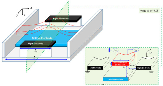
Figure 1.
3D schematic and side view of the in-plane and out-of-plane electrostatically actuated and initially curved flexible electrode-based micro-actuator.
Therefore, and in order to benefit from the increased sensitivity near such critical instability while avoiding the associated hazards, alternative operational strategies were suggested. Indeed, several research works have been communicated to possibly suggest ways to suppress the effect of this pull-in instability. Among these ideas we can cite delayed feedback, stochastic optimal control, the boundary control feedback law [9,10,11], operating the MEMS structure in dielectric liquid mediums [12], geometry incorporating raised side electrodes [13], considering high-frequency AC tensions [14], integrating lateral electrostatic transducers employing repulsive force [15], etc. Though these methods were successful in suppressing the effect of pull-in, they do have challenges, ranging from additional fabrication steps to high actuation voltages. Bi-stable curved micromechanical beams [16,17,18] and non-contact electrostatic microactuators using slit structures [19,20,21,22] were also some of the arrangements examined for bi-stability with extended range of operation and pull-in-free stable systems with reversible processes, respectively. A bi-stable structure can be defined as a structure capable of operating within two different equilibrium states at the same while actuating voltage. These kinds of structures have been intensively examined in the literature for extending the range of travel of the micro-actuator while extending the pull-in instability threshold. However, the main limitation of such bi-stable microstructures is that they were shown to be prone to temperature, residual stress, and even fringing fields variations in the parallel-plates actuation [23,24]. Furthermore, few out-of-plane (fringing field) non-contact electrostatic actuation arrangements were reported to be useful for different pull-in-free operations [16,25,26,27].
From the published research in the historical and recent literature, one can realize the continuous need for stable and sensitive MEMS micro-actuators with a large stable range of travel (stroke) and delayed pull-in instability. Hence, this work theoretically investigates the feasibility of both stroke and frequency tunability improvements when combining both parallel plates and fringing fields actuator-based micro-devices. In contrast to a previous work [26], a detailed analysis of the micro-actuator static and eigenvalue problem characteristics are presented. To this end, the paper is organized as follows: Modeling information about the electrostatic actuator design is first outlined, where the analytical expressions of both parallel plates and the fringing fields electrostatic forces are presented. A description of the reduced-order modeling (ROM) process is then exposed. The static as well as eigenvalue problems of the electrostatic actuator are solved and examined case by case. The key results of this investigation are finally summarized in a concluding section.
2. Problem Formulation and Beam Equation of Motion
The nonlinear beam equation governing the in-plane stroke of the electrostatic actuator shown in Figure 1 is first introduced. The actuator consists of a doubly clamped prismatic shallow-arched microbeam (Figure 1) with length L, width b, thickness h, cross-section area , and moment of area . The flexible electrode is made of polycrystalline silicon, which can be assumed to be a homogeneous isotopic elastic material of mass density kg/m, Young’s modulus GPa, and Poisson’s ratio . Since we will assume a case study below where the width of the microbeam is to be relatively greater than its thickness, an effective modulus of elasticity will then be considered.
Neglecting any axial and rotary inertia effects as compared to the transverse inertia effect, which is mainly dominant in our case, supposing that the microbeam’ thickness and its respective in-plane deflection , and assuming a nonlinear Euler–Bernoulli beam theory, the resultant equation governing the in-plane displacement and its respective boundary conditions can be written as:
where symbolizes the viscous damping coefficient, is the initial rise of the microbeam, and represent the distributed electrostatic force per unit length functions arising from the out-of-plane fringing field, respectively, and is the Heaviside step function. The in-plane electrostatic force can be analytically approximated using the following expression:
Note that the function cannot be obtained analytically in a closed form and will be only approximated using the fitting function available from the literature. As a case study, we consider a polysilicon shallow arch of length m, width m, thickness m, and two horizontal offsets of m and m. The motivations behind the selection of the above geometrical and material properties for the simulated actuator design stemmed from an existing design examined in [17]. The proposed MEMS structure can be adjusted, minimizing elaborate features and ensuring compatibility with standard microfabrication processes commonly used in the MEMS field while conserving the targeted electromechanical behavior.
The out-of-plane electrostatic force per unit length is a nonlinear function of the microbeam in-plane deflection and is estimated using the following numerical fitting function [26]:
where , , and are curve-fitting coefficients and their respective values are summarized in Table 1.

Table 1.
The fitting coefficients of the out-of-plane fringing fields electrostatic resultant force [26].
3. Numerical Reduced-Order Model
To get a numerical solution for the above Partial Differential Equation (PDE) and its respective boundary conditions governing the actuator’s in-plane deflection, Equations (1)–(4), have to be first discretized using the Galerkin expansion technique to yield an appropriate Reduced-Order Model (ROM) consisting of a set of coupled Ordinary-Differential Equations (ODEs) [16,23]. For this, the deflection of the micro-actuator can be approximated as:
where the test functions denote the linear normalized undamped mode-shapes of a doubly clamped beam, and the time-varying functions are their normalized modal amplitude coordinates. The ROM equations are to be constructed as follows: we first substitute Equation (5) into Equations (1)–(4), then multiply the outcome by for , use the associated orthogonality conditions of the mode shapes, and then integrate the resultant equations from 0 to 1. The outcome is a set of N coupled ODEs functions of the modal amplitudes where .
3.1. Static Equation
Since we are considering getting the static behavior of the actuator, we calculate its stationary deflection by setting all time-dependent terms in the ROM differential equations equal to zero and applying only constant DC voltages. Then, the modal amplitudes are replaced by unknown constant quantities . This results in a system of nonlinear algebraic equations in terms of those coefficients. The system is then solved numerically using the Newton–Raphson method.
The static solution is denoted by and it is given by
3.2. Eigenvalue Problem Equations
The eigenvalue problem of the actuator is carried out to calculate the variation of its natural frequencies under the effect of different DC voltages. For this, we consider the ROM modal amplitudes’ discretized equations, which can be written in a state-space form as:
where and denote the actuator normalized modal coordinates vector and a right-hand-side vector which is a nonlinear function of the modal coordinates , respectively. In order to capture all possible eigenfrequencies of the proposed actuator structure, the derived ROM includes symmetric and antisymmetric mode shapes. Next, we split the overall displacement into a static component , which constitutes the equilibrium state under DC voltage, and a dynamic component as follows:
Equation (7) can be rewritten in matric form as . Assuming minimal perturbation , the Taylor series expansion is employed while suppressing the higher-order terms, and, considering , the following equation can be derived:
Here, the Jacobian matrix is denoted by and it is evaluated at the MEMS equilibrium points. At a given DC voltage, the MEMS natural frequencies can be obtained by substituting the static solution into the matrix and evaluating its corresponding eigenvalues based on the numerical solving of the following characteristic equation:
where and det denote the identity matrix and the determinant operator, respectively.
4. Results
As a case study, we consider a shallow arch to be made of polycrystalline silicon with length m, width m, thickness m, and two horizontal offsets of m and m. First, in one of our previous papers [26], we have compared the simulated static deflection of the out-of-plane fringing-fields-based actuator arrangement with some experimental data that showed an acceptable level of agreement. Furthermore, in a separate publication [28], we have conducted a comparative analysis between the numerical simulations and data presented by another research group [17], resulting in a satisfactory level of agreement.
4.1. In-Plane Parallel Plates Actuation
Next, we consider investigating, as a first study, the variation of the maximum static deflection and the first three natural frequencies of the actuator under only parallel-plate DC electrostatic force. Figure 2 clearly demonstrates that the shallow arch would not experience a “bi-stability”-like behavior for all values of the actuator’s initial curvature, when the in-plane and out-of-plane voltages and are varied. As can be seen in Figure 2, for the case of m and lower, only one stable equilibrium position at one DC voltage parameter load is registered. For this particular case, the beam’s mid-point deflection starts to increase gradually, with a softening-like behavior, as revealed by a decrease in the first three natural frequencies, mainly governed by the quadratic nonlinearity which is dominated by the initial curvature, Figure 3a. Formerly, when reaching the flat arrangement, the arch displacement upsurge was swiftly accompanied by an increase in all natural frequencies, Figure 3a, indicating a strong cubic stiffening nonlinearity governed by the mid-plane stretching effect. Finally, the microbeam’s maximum deflection curve shows a slope going to infinity which indicates that pull-in instability has been reached (when the arch reaches the lower stationary electrode) and this is complemented by a drop to zero for the fundamental first frequency, Figure 3a.
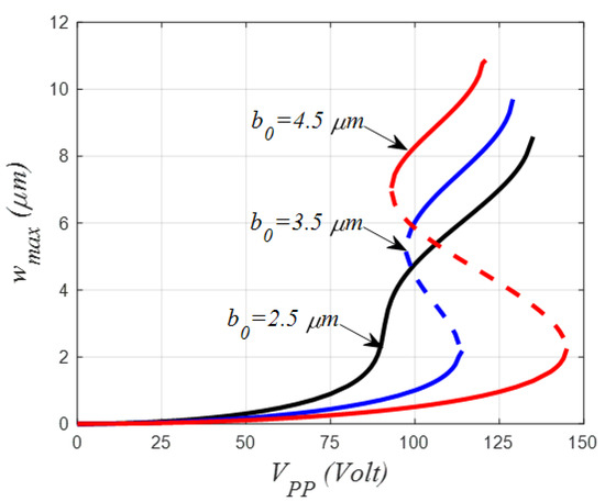
Figure 2.
Variation of the mid-point static deflection of the initially curved micro-electrode under parallel-plates DC load and for three different values of the initial rise.
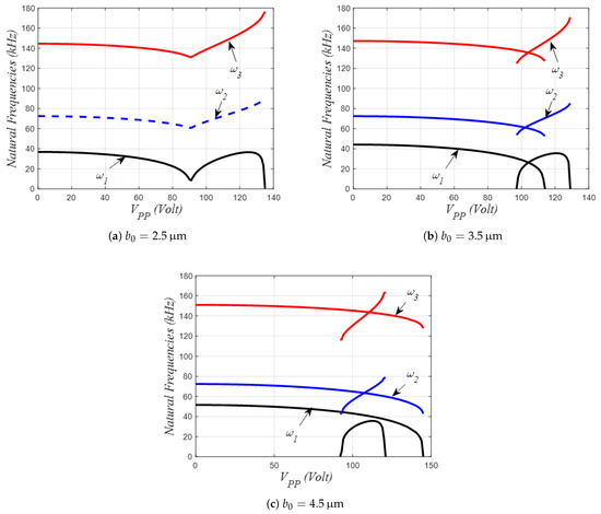
Figure 3.
Variation of the first lowest natural frequencies of the initially curved micro-electrode under parallel-plated DC load and for three different values of the initial rise.
For the cases of m and m, respectively, the shallow arch static curves show a bi-stable-like behavior with a possibility of coexistence between two stable equilibrium positions: one when the beam is curved up away from the lower stationary electrode (initial curvature) and a second one when the beam is concave down close to the lower electrode (counter curvature), Figure 2. In both cases, the static curves depicted in this figure are showing two slopes going to infinity illustrating both snap-through (when the beam travels from initial to counter curvature solutions or vice versa) and pull-in instabilities, respectively.
Nevertheless, only the case of m is showing that the arch can undergo the snap-through instability before the pull-in with the increase in the DC voltage because the registered snap-through voltage, in this particular case, is found to be lower than the pull-in voltage. Contrarily, for the case of m, the arch is forced to pull-in without snap-through, having recorded a snap-through voltage greater than the pull-in one. Regarding the variation of the natural frequencies, both cases show a monotonic decrease in all three first natural frequencies when the beam is in the first equilibrium state, concluded by a drop to zero for the fundamental frequency, indicating that instability corresponding to the snap-through voltage has been reached. Afterward, the shallow arch regains stability, accompanied by an increase in the three lowest natural frequencies when the arch is deflected in the neighborhood of the second stable state. This increase is then completed by a drop to zero for the fundamental frequency, corresponding to the pull-in instability. It is worth noting that all the frequency variation curves portrayed in Figure 3 are not displaying possible mode interactions, neither mode-veering nor mode-crossing.
4.2. Out-of-Plane Parallel-Plates Actuation
Next, the variation of the shallow arch maximum static mid-point deflection (Figure 4 and Figure 5) and their three lowest natural frequencies (Figure 6, Figure 7 and Figure 8) are examined for various out-of-plane DC fringing fields loads, while considering two lateral gap sizes of m and m.
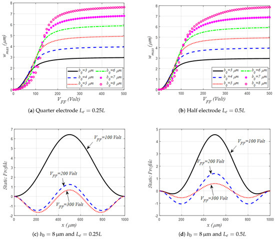
Figure 4.
Variation of the mid-point static deflection under out-of-plane fringing fields DC amplitude only and assuming different values of the initial rise for the case of m.
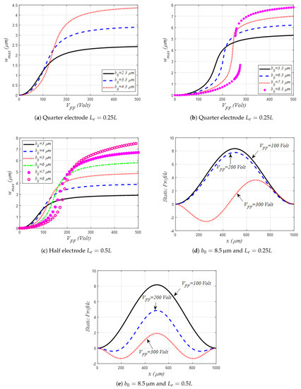
Figure 5.
Variation of the mid-point static deflection under out-of-plane fringing fields DC amplitude only and assuming different values of the initial rise for the case of m.
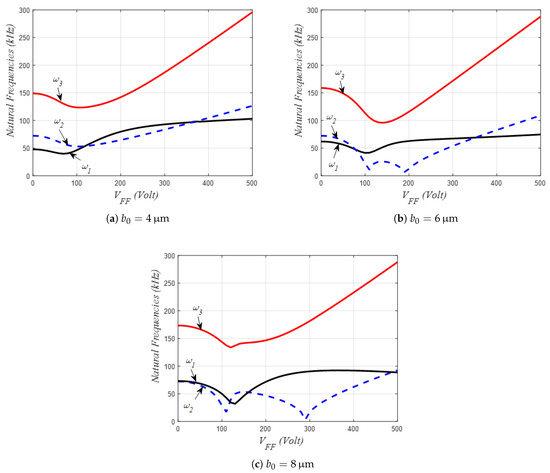
Figure 6.
Variation of the mid-point static deflection under out-of-plane fringing fields DC amplitude only, and assuming different values of the initial rise for the case of m and .
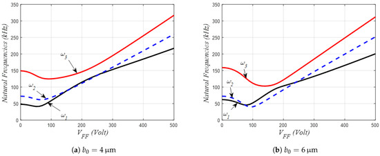
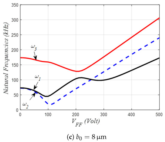
Figure 7.
Variation of the mid-point static deflection under out-of-plane fringing fields DC amplitude only, and assuming different values of the initial rise for the case of m and .
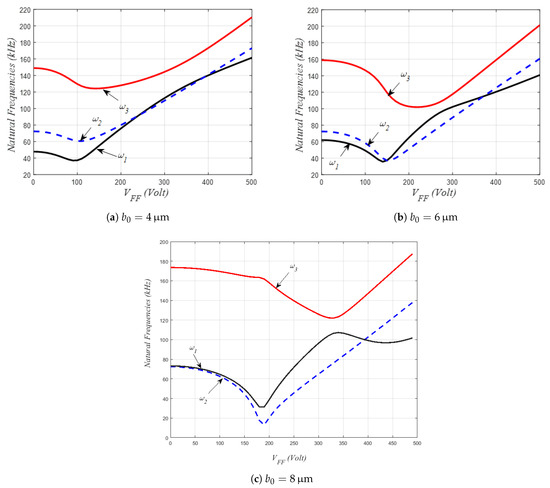
Figure 8.
Variation of the mid-point static deflection under out-of-plane fringing fields DC amplitude only, and assuming different values of the initial rise for the case of m and .
As can be seen from Figure 4 and Figure 5, all the static curves show a slow increase (bending regime) followed by a rapid one (catenary regime) for small DC loads [26]. Also, all displacement curves are concluded by a slow variation trend until the shallow arch static deflection converges to its initial rise-assumed value (elastic regime). In both Figure 4 and Figure 5, we have also investigated the effect of assuming quarter and half-sized side stationary electrodes, both considered symmetrically from the midspan of the flexible electrode. It is worth noticing that only a single stable equilibrium position was registered for each case, with a faster increase in the static deflection, with a higher DC load, for the case of the half-size electrode as compared to the quarter one. Nevertheless, when considering m, quarter-sized electrode, and higher initial rise value, two stable equilibria were possible at certain DC loads, illustrating a symmetry-breaking of the shallow arch under out-of-plane DC load actuation. Therefore, this is a good indication that such out-of-plane fringing field types of actuation are very interesting when considered from two different perspectives: increasing the electrostatic load through decreasing the lateral gap size and/or increasing the side electrode sizes, both resulting in faster stroke regarding the applied DC voltage. On the contrary, when considering the opposite case (higher lateral gap size and lower side electrode size), one can get a possible bi-stable stroke-like behavior.
In the following, Figure 6, Figure 7 and Figure 8 portray the effects of the shallow arch initial rise , the lateral gap size, and side electrodes size on the lowest three natural frequency variations. Figure 6 examines the case of m with quarter-sized side electrodes. As can be seen, for a lower value of initial rise, m, all three lowest frequencies are formerly decreasing with the DC load, certainly because of the dominance of the initial curvature effect, Figure 6a. Then, increasing further the DC load, the shallow arch reaches the near-flat shape, and consequently the mid-plane stretching effect induces an increase in the fundamental frequency until crossing the second natural frequency before departing away from each other. This is well known as the crossover phenomena, where both modes are considered to be linearly decoupled. Next, additional DC amplitude brings the second mode frequency to higher values until again crossing the first frequency in a second crossover occurrence. For the case of higher values of , Figure 6b,c, the same crossover occurrences were recorded, moreover the second mode frequency is showing two drops to lower values indicating the occurrence of the symmetry-breaking singularity: the arch static shape switching from a symmetric pattern to an antisymmetric one. It is worth noting here that for all above cases, the first and third frequencies did not show any clear indication of mode interaction among their variation with the DC load. On the contrary, when considering the case of the half-sized side electrode, Figure 7, and for higher values of and m, the first and third frequencies showed affirmative signs of modal interaction as their variation clearly exhibited an attraction-like behavior where both frequencies are coming close to each other with the increase in the DC load. The frequencies deviate away from each other in a manner of mode-veering as the DC voltage is further increased, Figure 7b,c. One concludes that such frequency veering occurs when both first and third frequencies are very close to each other. This fact could represent a positive mark of a strong mode localization, which could in turn be very practical for many MEMS applications ranging from energy harvesting to mass sensing.
The same process is also obtained when considering the case of m with half-sized side electrodes, as the first–second mode-crossings and the first–third mode-veering are arising at higher values of DC voltage, as compared to the case of m, Figure 8.
4.3. Combined Parallel-Plate and Fringing Field Actuations
It would be of great interest to many MEMS designers to understand the difference between the behavior of the shallow-arch actuator once actuated with a combined in-plane and out-of-plane electrostatic arrangement. Therefore, the case to be examined subsequently is the superposition of both parallel plates (PP) and fringing fields (FF) DC actuation arrangements, Figure 9 and Figure 10, for the case of m and half-sized side electrodes.
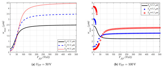
Figure 9.
Variation of the mid-point static deflection under out-of-plane fringing fields DC amplitude, assuming different values of the initial rise and two values of parallel-plate DC voltages, for the case of m and .
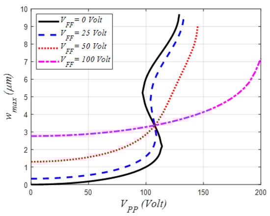
Figure 10.
Variation of the mid-point static deflection under out-of-plane fringing fields DC amplitude, assuming different values of the initial rise and two values of parallel-plate DC voltages, for the case of m, m and .
Figure 9 shows the mid-point static deflection of the shallow arch considering three different values of , two fixed values of the PP DC load and when varying the out-of-plane FF DC voltage. Recall, from Figure 2, that for lower values of , such as m, the shallow arch possesses only one stable equilibrium under PP DC load. Therefore, for this particular case, and when assuming lower (50 V) or higher (100 V) PP DC voltages (Figure 9a and Figure 9b, respectively), the shallow arch mid-point static displacement showed only one stable solution in spite of having two opposite stroke directions: downward toward the lower stationary electrode for the case of 50 V and upward away from the same electrode for the case of 100 V, both when increasing the FF DC load.
However, when increasing the initial rise to higher values, such as m and m. the shallow arch static deflection may exhibit two distinct but coexisting stable positions: one for lower values of PP DC load (i.e., V) and one for higher values of PP DC load (i.e., V). For the case of V PP DC load and increasing the FF DC load, Figure 11a, the shallow-arch static deflection is showing a mono-stable-like behavior with greater stroke when considering the higher initial rise values. Controversially, when increasing the PP DC load to V, the shallow arch static profile displayed a bi-stable-like hysteresis behavior: two distinct and coexisting stable strokes: one downward increasing motion toward the lower stationary when the arch is initially in its first stable upper position and one upward, turning away from the same electrode when the arch is initially in its second lower stable position, both when increasing the FF DC load. When the FF DC load reaches a threshold value, the registered bi-stable behavior switches to a mono-stable one, attracting the shallow arch to the straight-like outline under the effect of the FF DC load.
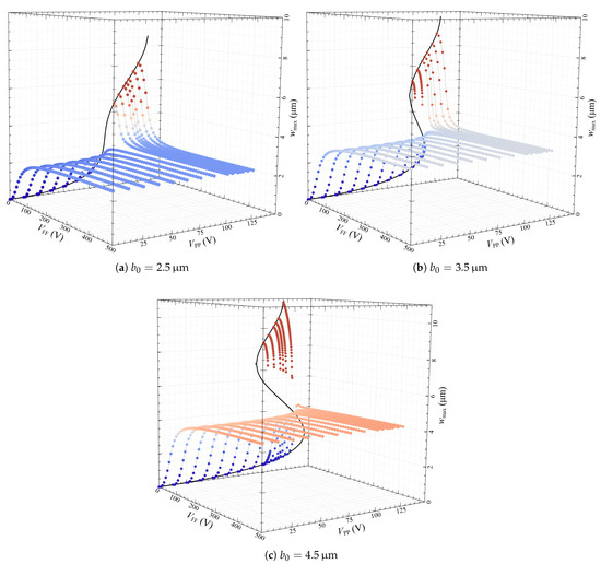
Figure 11.
Variation of the mid-point static deflection under a combination of in-plane parallel-plate and out-of-plane fringing fields DC amplitudes and assuming different values of the initial rise for the case of m and .
Figure 10 shows the mid-point static deflection of the shallow arch for the case of m, four fixed values of the FF DC load (m and half sized side electrodes), and when varying the in-plane PP DC amplitude. Recall, from Figure 2, that for such an initial rise case, the shallow arch possesses a hysteresis bi-stable-like static behavior under PP DC load. Then, for this particular case, and when we gradually increased the FF DC amplitude (Figure 10), the shallow-arch mid-point static displacement bi-stable band is reduced until showing a mono-stable-like response with limited stroke. The existence of an invariant displacement for different voltages, corresponding to the point where the microbeam is almost straight, can also be noticed (Figure 10), with a maximum displacement equal to the initial rise . At this point, the out-of-plane fringing fields have no effect on the microbeam because the electrostatic forces are balanced from the upper and lower side of the microbeam.
The combined effect of the microbeam static deflection under in-plane parallel-plate and out-of-plane fringing fields DC amplitudes, is shown in Figure 11. One can remark that with a highly applied voltage (more than 100 V), the microbeam is strongly bound to a straight beam-like configuration where the maximum displacement is equal to the initial rise . This behavior is verified for the three different tested initial rises m, m, and m shown in Figure 11a–c, respectively. For lower voltages, the behavior is dominated by with a classical response of a parallel plate actuator. Nevertheless, the introduction of relatively low values of can mitigate the effect of , leading to an attenuation of the amplitudes which reduces nonlinear responses such as snap-through and pull-in. In Figure 11b,c, the introduction of can even switch the response from mono- to bi-stable potential well solutions. Since the transition between these regimes requires relatively low applied voltages, this behavior could be further investigated with a dynamic actuation to develop new detection mechanisms, such as mass-sensing applications.
Figure 12 shows the variation of the lowest three natural frequencies of the shallow arch when considering a combined effect of PP and FF actuations. The effect of varying the FF and PP voltages, and for several values of the initial rise, is portrayed. As seen, the first/second frequencies’ crossover and first/third frequencies’ veering are further noticeable at higher values of the arch’s initial rise and PP DC load, respectively, when varying the FF load. On the contrary, when allowing the PP DC load to vary for discrete values of FF amplitude lower than V, all of the lowest three frequencies are monotonically varying without a single sign of mode-veering nor mode-crossing. For around V, V and for relatively large initial rises (m and m in Figure 12b,c, the existence of a bi-stable solution in the static domain generates new natural frequencies corresponding to each of the static solutions. On the other hand, the responses shown in Figure 12 indicate that, for such a combined actuation design, it would be more practical to vary the FF DC load rather than the PP load if one needs to design a localized mode-based sensor with better stroke and improved tunability.
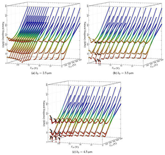
Figure 12.
Variation of the first three lowest natural frequencies under a combination of in-plane parallel-plate and out-of-plane fringing fields DC amplitudes and assuming different values of the initial rise for the case of m and .
To detect possible veering and crossover between the different modes of the shallow arch microbeam calculated and displayed by Figure 12, density plots are generated for three possible configurations: (i) crossing between the first and second natural frequencies shown in Figure 13a–c, (ii) veering between first and third natural frequencies shown in Figure 13d–f, and (iii) crossing between two times the first natural frequency and the third one shown in Figure 13g–i. For the first and third cases, the idea is to show possible one-to-one and three-to-one internal resonances that could arise in the microbeam dynamic response, such as those reported in the literature [29]. The second case can be used to detect possible localization phenomena between the first and third modes [30]. Figure 13a,b shows that crossing can be obtained between the first and second natural frequencies for any applied voltage until V. For the applied voltage , the crossing occurs around V for the case where m. However, for the other initial rises (m and m), the crossing occurs for two different values of : V and V for m and V and V for m.
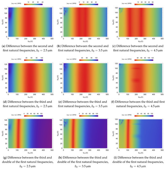
Figure 13.
Density plot of the natural frequency differences under a combination of in-plane parallel-plate and out-of-plane fringing fields DC amplitudes and assuming different values of the initial rise for the case of m and .
Crossing between the third and double of the first natural frequencies, corresponding to the second case, is found to be specific to nearly a single voltage and almost independent of the voltage, as shown in Figure 13g–i. It is located around V for all value of , with a very small decrease of as is increased, and also a very small increase of as is increased.
For the second case, where the difference between first and third natural frequencies is shown in Figure 13d–f, three different behaviors are observed here for the plot region where the minimum frequency value of the difference is calculated. For m, in Figure 13d, the applied voltage is around V and can vary from 0 to V, with a minimum frequency difference of kHz. While for m, in Figure 13e, we detected that can vary from 0 to V and should be around V. The minimum frequency difference is around kHz. For m, in Figure 13f, the minimum frequency difference is about kHz, and it is obtained for the applied voltages V and V.
5. Conclusions
The nonlinear static behavior and eigenvalue problem of a clamped–clamped initially curved flexible electrode when actuated by in-plane parallel-plates and out-of-plane fringing fields electrostatic loads was investigated. The respective problems’ nonlinear equations were solved numerically for various values of DC loads using a reduced-order mode obtained through a Galerkin modal expansion discretization technique. Possible scenarios of mono-stable and bi-stable large-stroke micro-actuator were exhibited based on how the micro-electrode is actuated: either by individual actuation through allowing only PP voltage or FF load at one time, or by a combined PP/FF actuation process. Results also displayed possible mode interaction such as linearly coupled interaction between the first and third natural frequencies that were shown to be highly dependent on the shallow flexible electrode’s initial rise and the size of the side out-of-plane actuating stationary electrodes. The proposed MEMS device is tunable in terms of modal interactions and mode veering. For a particular set of design parameters, the veering zone between the first and third modes can be electrostatically adjusted and can reach kHz.
This work will be extended to solve the full dynamic behavior of such a combined in-plane and out-of-plane electrically actuated resonator. This actuation method holds great promise as a highly sensitive mass sensor. As shown in this work, it demonstrates a greater flexibility in coupling multiple vibrational modes, including both lower-order and higher-order modes, by only varying the applied DC voltages. The introduction of mass onto the sensor disrupts these vibrational modes, leading to the localization of the dynamic motion of the device over a single mode. This, in turn, establishes the foundation for the development of a highly sensitive mass sensor using a single cantilever beam. We also intend to study the influence of electrodes’ geometrical properties while looking at any probability of mode localization for mass-sensing applications.
Future work will include the experimental analyses of such actuators, incorporating the combined influence of out-of-plane fringing electrostatic fields and in-plane parallel-plate fields. This effort aims to comprehensively explore potential occurrences of modal interaction resonance within the vicinity of the frequency veering.
Author Contributions
Conceptualization, methodology, visualization, validation and draft writing H.M.O., F.N. and N.K.; manuscript revision and supervision, H.M.O., F.N. and N.K. All authors have read and agreed to the published version of the manuscript.
Funding
This research received no external funding.
Data Availability Statement
The data that support the findings of this study are available within the article.
Acknowledgments
This project has been performed in cooperation with the EIPHI Graduate School (contract “ANR-17-EURE-0002”). The first author acknowledges the support provided by the MedTech at the South Mediterranean University, Lac2, Tunis.
Conflicts of Interest
The authors declare no conflict of interest.
References
- Maluf, N.; Williams, K. An Introduction to Microelectromechanical Systems Engineering; Artech House: New York, NY, USA, 2004. [Google Scholar]
- Elwenspoek, M.; Wiegerink, R.J. Mechanical Microsensors; Springer Science & Business Media: Berlin/Heidelberg, Germany, 2001. [Google Scholar]
- Marques, A.F.; Castelló, R.C.; Shkel, A. Modelling the Electrostatic Actuation of MEMS: State of the Art 2005; Technical Report; Institut d’Organització i Control de Sistemes Industrials: Barcelona, Spain, 2005. [Google Scholar]
- Yang, S.; Xu, Q. A review on actuation and sensing techniques for MEMS-based microgrippers. J. Micro-Bio Robot. 2017, 13, 1–14. [Google Scholar] [CrossRef]
- Algamili, A.S.; Khir, M.H.M.; Dennis, J.O.; Ahmed, A.Y.; Alabsi, S.S.; Ba Hashwan, S.S.; Junaid, M.M. A review of actuation and sensing mechanisms in MEMS-based sensor devices. Nanoscale Res. Lett. 2021, 16, 1–21. [Google Scholar] [CrossRef] [PubMed]
- Nathanson, H.C.; Newell, W.E.; Wickstrom, R.A.; Davis, J.R. The resonant gate transistor. IEEE Trans. Electron Devices 1967, 14, 117–133. [Google Scholar] [CrossRef]
- Newell, W.E. Miniaturization of Tuning Forks: Integrated electronic circuits provide the incentive and the means for orders-of-magnitude reduction in size. Science 1968, 161, 1320–1326. [Google Scholar] [CrossRef]
- Zhang, W.M.; Yan, H.; Peng, Z.K.; Meng, G. Electrostatic pull-in instability in MEMS/NEMS: A review. Sens. Actuators A Phys. 2014, 214, 187–218. [Google Scholar] [CrossRef]
- Shang, H. Pull-in instability of a typical electrostatic MEMS resonator and its control by delayed feedback. Nonlinear Dyn. 2017, 90, 171–183. [Google Scholar] [CrossRef]
- Qiao, Y.; Jiao, Y.; Xu, W. Stabilization of electrostatic MEMS resonators using a stochastic optimal control. Chaos Solitons Fractals 2022, 154, 111702. [Google Scholar] [CrossRef]
- Edalatzadeh, M.S.; Vatankhah, R.; Alasty, A. Suppression of dynamic pull-in instability in electrostatically actuated strain gradient beams. In Proceedings of the 2014 Second RSI/ISM International Conference on Robotics and Mechatronics (ICRoM), Tehran, Iran, 15–17 October 2014; pp. 155–160. [Google Scholar]
- Legrand, B.; Rollier, A.S.; Collard, D.; Buchaillot, L. Suppression of the pull-in instability for parallel-plate electrostatic actuators operated in dielectric liquids. Appl. Phys. Lett. 2006, 88, 034105. [Google Scholar] [CrossRef]
- Kudrle, T.; Shedd, G.; Wang, C.; Hsiao, J.; Bancu, M.; Kirkos, G.; Yazdi, N.; Waelti, M.; Sane, H.; Mastrangelo, C. Pull-in suppression and torque magnification in parallel plate electrostatic actuators with side electrodes. In Proceedings of the TRANSDUCERS’03, 12th International Conference on Solid-State Sensors, Actuators and Microsystems. Digest of Technical Papers (Cat. No. 03TH8664), Boston, MA, USA, 8–12 June 2003; Volume 1, pp. 360–363. [Google Scholar]
- Lakrad, F.; Belhaq, M. Suppression of pull-in instability in MEMS using a high-frequency actuation. Commun. Nonlinear Sci. Numer. Simul. 2010, 15, 3640–3646. [Google Scholar] [CrossRef]
- Daeichin, M.; Miles, R.; Towfighian, S. Lateral pull-in instability of electrostatic MEMS transducers employing repulsive force. Nonlinear Dyn. 2020, 100, 1927–1940. [Google Scholar] [CrossRef]
- Krakover, N.; Ilic, B.R.; Krylov, S. Displacement sensing based on resonant frequency monitoring of electrostatically actuated curved micro beams. J. Micromech. Microeng. 2016, 26, 115006. [Google Scholar] [CrossRef] [PubMed]
- Krylov, S.; Ilic, B.R.; Lulinsky, S. Bistability of curved microbeams actuated by fringing electrostatic fields. Nonlinear Dyn. 2011, 66, 403–426. [Google Scholar] [CrossRef]
- Alneamy, A.M.; Ouakad, H.M. Inertia mass bio-sensors based on snap-through phenomena in electrostatic MEMS shallow arch resonators. Int. J. Mech. Sci. 2023, 238, 107825. [Google Scholar] [CrossRef]
- Lee, K.B. Non-contact electrostatic microactuator using slit structures: Theory and a preliminary test. J. Micromech. Microeng. 2007, 17, 2186. [Google Scholar] [CrossRef]
- Small, J.; Irshad, W.; Fruehling, A.; Garg, A.; Liu, X.; Peroulis, D. Electrostatic fringing-field actuation for pull-in free RF-MEMS analogue tunable resonators. J. Micromech. Microeng. 2012, 22, 095004. [Google Scholar] [CrossRef]
- Su, J.; Yang, H.; Fay, P.; Porod, W.; Bernstein, G. A surface micromachined offset-drive method to extend the electrostatic travel range. J. Micromech. Microeng. 2009, 20, 015004. [Google Scholar] [CrossRef]
- Krakover, N.; Ilic, B.R.; Krylov, S. Micromechanical resonant cantilever sensors actuated by fringing electrostatic fields. J. Micromech. Microeng. 2022, 32, 054001. [Google Scholar] [CrossRef]
- Sulfridge, M.; Saif, T.; Miller, N.; O’Hara, K. Optical actuation of a bistable MEMS. J. Microelectromech. Syst. 2002, 11, 574–583. [Google Scholar] [CrossRef]
- Ouakad, H.M. Electrostatic fringing-fields effects on the structural behavior of MEMS shallow arches. Microsyst. Technol. 2018, 24, 1391–1399. [Google Scholar] [CrossRef]
- He, S.; Mrad, R.B.; Chong, J. Repulsive-force out-of-plane large stroke translation micro electrostatic actuator. J. Micromech. Microeng. 2011, 21, 075002. [Google Scholar] [CrossRef]
- Ouakad, H.M. Static response and natural frequencies of microbeams actuated by out-of-plane electrostatic fringing-fields. Int. J. Non-Linear Mech. 2014, 63, 39–48. [Google Scholar] [CrossRef]
- Kambali, P.N.; Pandey, A.K. Capacitance and force computation due to direct and fringing effects in MEMS/NEMS arrays. IEEE Sens. J. 2015, 16, 375–382. [Google Scholar] [CrossRef]
- Mohammad, T.; Ouakad, H. Static, eigenvalue problem and bifurcation analysis of MEMS arches actuated by electrostatic fringing-fields. Microsyst. Technol. 2016, 22, 193–206. [Google Scholar] [CrossRef]
- Ouakad, H.M.; Sedighi, H.M.; Younis, M.I. One-to-one and three-to-one internal resonances in MEMS shallow arches. J. Comput. Nonlinear Dyn. 2017, 12, 051025. [Google Scholar] [CrossRef]
- Rabenimanana, T.; Walter, V.; Kacem, N.; Le Moal, P.; Bourbon, G.; Lardies, J. Enhancing the linear dynamic range of a mode-localized MEMS mass sensor with repulsive electrostatic actuation. Smart Mater. Struct. 2021, 30, 07LT01. [Google Scholar] [CrossRef]
Disclaimer/Publisher’s Note: The statements, opinions and data contained in all publications are solely those of the individual author(s) and contributor(s) and not of MDPI and/or the editor(s). MDPI and/or the editor(s) disclaim responsibility for any injury to people or property resulting from any ideas, methods, instructions or products referred to in the content. |
© 2023 by the authors. Licensee MDPI, Basel, Switzerland. This article is an open access article distributed under the terms and conditions of the Creative Commons Attribution (CC BY) license (https://creativecommons.org/licenses/by/4.0/).