Article

Workspace Description and Evaluation of Master-Slave Dual Hydraulic Manipulators

Key Laboratory of High Efficiency and Clean Mechanical Manufacture of Ministry of Education, National Demonstration Center for Experimental Mechanical Engineering Education, School of Mechanical Engineering, Shandong University, Jinan 250061, China
*
Author to whom correspondence should be addressed.
Actuators 2023, 12(1), 9; https://doi.org/10.3390/act12010009
Submission received: 2 November 2022 / Revised: 2 December 2022 / Accepted: 16 December 2022 / Published: 23 December 2022
(This article belongs to the Special Issue Advanced Technologies and Applications in Robotics)

Abstract

:
Nuclear power plant emergency robots are robots used to respond to significant public safety incidents, such as uncontrolled radioactive sources and nuclear catastrophe leaks. However, there are no standardized evaluation criteria for the optimal design of the robots. We offer a quantitative analytic algorithm for optimizing nuclear power plant emergency robots to address this issue. The method optimizes the structural parameters of the robot in accordance with the workspace by analyzing, comparing, and evaluating the workspace. The approach comprises constructing a kinematic model of the mechanical arm and proposing an optimization algorithm based on the alpha shape to accurately describe the manipulator workspace; employing the proposed convex hull algorithm to quantitatively analyze and evaluate the workspace generated by different solutions in terms of area, volume, task demand, Structural Length Index and Global Conditioning Index; and determining the robotic arm joint parameters by selecting the optimum workspace design solution. Using the suggested algorithm, we optimize the design of the master and slave robotic arms of the nuclear power plant emergency robots. Theoretical calculations and simulation results demonstrate that the method is an effective and practical evaluation technique that not only accurately describes the workspace but also optimizes the design of the nuclear power plant emergency robots.

1. Introduction

In recent years, the employment of robots in nuclear power plants has become widespread. In nuclear power plants, robots such as nuclear power plant underwater robots [1,2], nuclear power plant inspection robots [3,4,5], nuclear power plant emergency robots [6] and other robots are frequently utilized. Unlike conventional industrial robots, nuclear power plant robots must perform tasks in unique environments and, as a result, must be more reliable and secure [7]. The nuclear power plant emergency robot (NPPER) was designed to handle serious safety incidents, such as uncontrolled radioactive sources and nuclear catastrophe leaks. It allows the robot to operate remotely at a nuclear accident site by traversing barriers, climbing, picking up, carrying, and turning valves [8,9,10].
However, due to the unique nature of NPPERs, there is no uniform standard for the design of NPPERs, as they are all individually suited to the requirements of the task. Zhang Zhonglin et al. [5] designed a small, lightweight nuclear power plant inspection robot based on the domestic and international representative configurations of nuclear power robots. Jong Seog Kim et al. [11] developed a robot for operation in nuclear power plants to address the three main obstacles faced. Daewon Kim et al. [12] proposed a robot capable of autonomous driving and wall climbing based on the task requirements of high-risk and difficult-to-measure areas of nuclear radiation. However, since these robots were designed using their own development standards, it is difficult to directly apply them to other nuclear power plant robots.
The NPPER uses a dual hydraulic robot arm with master-slave control functions to operate in confined areas. However, the absence of established evaluation criteria for NPPERs makes the optimal design of the robots an extremely challenging and complicated task. To address this issue, we chose to optimize the structural design by dealing with the robot’s workplace. In response to the varying workspace requirements of various NPPERs, we evaluate the design of the robot arm in terms of the workspace’s area, volume, Structural Length Index, and Global Conditioning Index in order to determine the optimal robot arm joint parameters and optimize the design of the robot.
The current main methods for solving the robot arm workspace can be divided into three categories: geometric, analytical, and discretization methods [13,14]. Geometric methods are mainly used for solving the workspace of planar robots, which can obtain the sectional interface of the workspace and are intuitive but are limited by the degrees of freedom and cannot accurately describe the workspace of multi-degree-of-freedom robots [15,16]. The analytical technique is a method based on the Jacobi matrix for solving the robot workspace, which is a sophisticated solution approach that is unsuitable for robotic arms with multi-degree-of-freedom [15,17]. The discretization approach relies on the robot’s forward kinematics to solve the workspace; it is straightforward, applicable to any type of robot construction, and the most widely used [18,19,20].
As one of the scatters point methods, Monte Carlo is appropriate for computing the workspace solutions of multi-degree-of-freedom robotic arms exposed to complex constraints [18,21,22,23,24]. Despite its widespread application, the classical Monte Carlo approach has the following limitations: (1) The classical Monte Carlo method’s robot workspace accuracy depends on the number of random sample points, and when the number is insufficient, the workspace boundary is noisy and not smooth. Increasing the number of sampling points improves the issue of insufficient points at the workspace barrier, but most of the points still occur at the non-working space boundary, resulting in a lot of computational waste [25,26]. (2) The coordinate transformation equations in the positive kinematic equations of the robot are nonlinear, and the Monte Carlo approach yields uniform distributions for the joint angle values. After mapping from joint space to Cartesian space, the distribution of workspace points in the total workspace no longer fulfills the uniform distribution [27], making it impossible to produce correct workspace borders. Therefore, the classical Monte Carlo method is wasteful and may not solve the accuracy problem. The Gaussian growth approach [27] or iterated point generation [25,26] are used to improve the robot’s workspace structure and boundaries.
The volume of the workspace affects the qualitative and quantitative evaluation, comparison, and analysis of the workspace. For the design of robot workspaces, it is therefore essential to quickly and precisely determine the three-dimensional convex envelope and volume of the workspace. Typically, the volume of the workspace is determined by first drawing the 3D convex envelope of the workspace, which is followed by numerical integration [28,29,30]. Nevertheless, the evaluation of a workspace for a master-slave dual robot arm remains challenging due to the following challenges. (1) NPPERs must balance cost and dependability with workspace to maximize robot arm flexibility [7,31,32]. Thus, new quantitative analytic methods must be developed to evaluate the workspace so that it meets the robot’s operating tasks and is cost-effective and reliable. (2) Applying Monte Carlo and convex hull algorithms to the NPPER, which has up to 12 degrees of freedom in its dual manipulators, may result in a blurred workspace boundary, inaccurate calculation outputs, and also many computations. (3) The aforementioned algorithms are designed for slave robotic arms (SRMs) and cannot be applied to NPPERs with up to two master robotic manipulators (MRMs) and two SRMs utilizing master-slave control. Due to these factors, the existing algorithms cannot be applied directly to the NPPER’s manipulators.
To solve these three issues, (1) we offer an optimization algorithm based on alpha shape (OAAS) that employs the alpha shape algorithm to extract the scatter set bounds and generates two-dimensional convex hulls using circular trajectories to reconstruct the graphs, making the workspace uniform. This approach decreases the computing burden of generating the workspace and overcomes the problem of unclear spatial boundaries caused by uneven scatter point distribution. (2) We present a convex hull approach for computing the 3D volume envelope. The technique uses the method of traversing matrices to reduce the number of integration operations, enhance computational performance, and obtain a more accurate 3D envelope and volume of the workspace, which may be used to evaluate the optimally constructed workspace. (3) We integrate the suggested quantitative analysis, comparison, and evaluation mechanism with the task requirements of an NPPER to build a workspace with the best degree of conformance to the real necessary workspace, therefore decreasing the design complexity and manufacturing cost and enhancing the practicality and reliability of the workspace. (4) We designed the MRM’s workspace based on the SRM’s workspace using a geometric mapping algorithm. Finally, we verified the effectiveness and practicability of the proposed optimization technique on an NPPER.
This article is organized as follows: Section 2 presents the task requirements and initial workspace planning for the NPPER. The algorithm employed to characterize the two-dimensional workspace is presented in Section 3. Section 4 presents the algorithm for evaluating the workspace using a three-dimensional convex hull. In Section 5, algorithms for designing master-slave hydraulic arm workspaces are presented. Section 6 presents the conclusions of this work.

2. NPPER

NPPERs are based on robots used in nuclear power plant accidents for emergency rescue (e.g., a nuclear leak). Section 2.1 lists NPPER task requirements. Based on the task needs, Section 2.2 proposes a tentative workspace arrangement for NPPER’s twin SRM.
As shown in Figure 1, the workspace Ω m denotes the space in which the MRM’s trajectories are constrained. Set Ω s represents the SRM’s workspace. There may be barriers within the workspace Ω s . These major obstacles correspond to Ω b 1 , Ω b 2 , and Ω b 3 . The real workspace of the SRM is therefore Ω s w = Ω s ( Ω b 1 + Ω b 2 + Ω b 3 ) .

2.1. Task Requirements

The design concept of the NPPER is based on the application scenario, investigating the performance needs of the robot based on the task requirements, and offering a planning solution for robot arm workspaces. The following requirements analysis was conducted on the designed robot:
1
To facilitate the disposal of radioactive materials that have leaked, the opening and closing of valves, and the removal of large impediments, a single robotic arm with an end load of 25 kg is required. The manipulator must also be flexible and have a reasonable working space to achieve the required movements to ensure that the emergency response is carried out smoothly.
2
To investigate accident scenes, the robot should be compact and able to travel through single passageways and doors to enter inside regions such as control rooms for investigation or operation.
3
The high radiation intensity at the site of a nuclear accident can be extremely damaging to humans. The robot has been developed to keep the operator away from the dangerous environment, so the robot’s dual robotic arms need to have remote control capabilities.
4
Nuclear accidents produce smoke, vapor, and radioactive substances. Robotic arms are necessary to be resistant to radiation and interference as well as highly dependable while avoiding excessive costs.
5
The technique of operation should be easily comprehended and learned by the operator, hence boosting the operability and simplicity of the double robotic arm’s operation and minimizing the risk of adverse outcomes resulting from faulty operation.
6
The control algorithm of NPPERs employed in nuclear accident relief must have rapid kinematic calculation speed and efficient and intuitive obstacle avoidance methods to enable real-time master and slave motion following, safety, and intuitive operation.
We propose an NPPER with dual SRMs, dual MRMs, and a remote master-slave homogenous control system, based on the aforementioned task requirements and the specifics of the working scenario. Each MRM or SRM has six degrees of freedom. To increase the operator’s intuition and the safety of the SRM operation, the primary structural dimensions of the MRM are diminished in proportion to those of the SRM.

2.2. Preliminary Planning of the Workspace

The workspace of a manipulator is the maximum range in three-dimensional space that the arm’s end-effector can reach. Based on the task requirements outlined in Section 2.1, we have originally planned the required workspace for the NPPER. A large workspace increases the flexibility of SRMs, but it also increases their complexity, manufacturing costs, and actuator count. Therefore, NPPERs must organize their workspaces under the requirements of their tasks.
We planned the NPPER’s workspace for two-armed collaboration and single-armed operation tasks. The workspace planning was separated into three subspaces: the dual-arm collaborative subspace, which is used to execute difficult and important operational activities, such as opening doors with two arms and picking up heavy things; the single-arm operational subspace, which accomplishes operational chores that can be accomplished with a single arm, such as clearing barriers surrounding the robot; and the robot body region, which must be planned outside the robot arm workspace to reduce interference.
The designed manipulator should have a hydraulic drive solution to allow it to work in a high-radiation environment after a nuclear accident. Due to the limited joint range of the hydraulic arm with a high load ratio, we have employed a six DOF hydraulic manipulator solution to increase the SRM’s flexibility. We employ master-slave control to solve the problem of the cumbersome operation of the dual SRM with multiple DOFs. As depicted in Figure 1, the operator controls the MRM at proximal, causing the SRM at remote to assume the same position as the MRM in real-time. The operator operates the SRM remotely through monitors attached to the SRM, allowing for obstacle avoidance and safe operation of the SRM.

3. Workspace Generation Algorithms

This section proposed the OAAS algorithm based on Monte Carlo and alpha shape algorithms to obtain an accurate and uniform density workspace. Section 3.1 introduces the classical Monte Carlo method; Section 3.2 presents the OAAS algorithm.

3.1. Monte Carlo Approach

This section discusses the classical Monte Carlo approach used to produce the robot arm workspace and analyzes the challenges associated with the Monte Carlo method. Let q = q 1 , q 2 , q 3 , q 4 , q 5 , q 6 T represent the joint coordinate vector of the NPPER with six DOFs. The Monte Carlo approach involves generating a large number of random vectors q and solving a positive kinematic problem for each random vector to determine the end effector’s position X R 3 .
The components of each random vector q are created arbitrarily using the traditional Monte Carlo approach.
q k = q k min + q k max q k min r k
where q k m a x , q k m i n is the upper and lower bound of the joint coordinate q k , respectively. The variable r k is a uniform random number in [ 0 , 1 ] . The resulting workspace is a point cloud that can be graphically depicted in three-dimensional space.
As illustrated in Figure 2a, the blue point cloud consists of 50,000 Monte Carlo-generated points, however, the black line represents the actual workspace boundary, indicating that the Monte Carlo workspace is inaccurate and uneven [26]. Some sections of the Monte Carlo workspace have more points (e.g., high-probability regions in Figure 2a); other regions have fewer point clouds, particularly those near the workspace’s edge (e.g., low-probability regions in Figure 2a). As a result, Monte Carlo’s workspace has an uneven point density and an unclear boundary.
The reason for the uneven workspaces is the highly non-linear nature of the positive kinematic transformation. Although the joint coordinates generated by the Monte Carlo method are uniformly distributed, the mapping from joint space to Cartesian space is highly nonlinear, which results in the generation of uneven workspace points. To address this problem, we propose the OAAS algorithm in Section 3.2 based on the Monte Carlo method and the alpha shape algorithm to map a uniformly distributed robotic arm workspace.

3.2. OAAS Algorithm

The alpha shape algorithm extracts the boundary of a scattered set of points and reconstructs the corresponding graph. This border is neither necessarily convex nor continuous, but it approximates the outline of the set of discrete points. Adjusting the parameters can make the boundary more or less distinct. However, the complexity of the classical alpha shape technique is excessively high, and the computational efficiency is low when the number of data points is too significant. We optimize the alpha shape technique and propose the OASS algorithm by incorporating the Monte Carlo method to obtain a workspace with uniform density distribution and obvious borders, as illustrated in Figure 2b.
In this paper, the following OAAS algorithm is proposed: First, Monte Carlo generates a point set P . Then, a circle of radius α is assumed to roll outside the point set, and if α is chosen suitably, the circle will not fall into the gap between the point sets. Finally, the path that the circle rolls over is the point set’s boundary. The detailed steps are as follows:
(1)
Calculating the positive kinematics of the SRM, providing the conversion formula from joint space to Cartesian space.
6 0 T = 1 0 T 2 1 T 3 2 T 4 3 T 5 4 T 6 5 T
Substituting the known DH parameters into Equation (2) results in a function between the robot end position coordinates and the joint variables as follows:
p x = 130 c 1 + 660 c 12 370 s 14 + 369 c 5 c 4 s 1 s 4 c 1 s 23 c 123 + 369 s 5 s 14 + c 4 c 1 s 23 c 123 370 c 4 c 1 s 23 c 123 163 c 1 s 23 + 163 c 123 p y = 130 s 1 + 660 c 2 s 1 370 c 1 s 4 + 369 c 5 c 14 s 4 s 123 c 23 s 1 369 s 5 c 1 s 4 + c 4 s 123 c 23 s 1 370 c 4 s 123 c 23 s 1 163 s 123 + 163 c 23 s 1 p z = 660 s 2 + 163 c 2 s 3 + 163 c 3 s 2 + 370 c 4 c 2 s 3 + c 3 s 2 369 c 4 s 5 c 2 s 3 + c 3 s 2 + 369 c 5 s 4 c 2 s 3 + c 3 s 2 + 153 2
with
s i j = sin q i + q j , c i j = cos q i + q j , s i = sin q i , c i = cos q i
where p x , p y , and p z denote the x, y, and z coordinates of the end-effector of the manipulator, respectively.
(2)
A set P of points with number n is generated using the Monte Carlo approach (see Equation (1)).
(3)
The value of the discriminant radius α controls the fineness of the border; the smaller the α value, the finer the boundary.
(4)
Draw a circle with radius α through any two points p 1 and p 2 from the set P of points obtained in step 2. If there are no further data points within either circle, the points p 1 and p 2 are designated boundary points and their connecting lines are boundary line segments.
(5)
If the distance between p 1 and p 2 exceeds 2 α , step 4 is skipped. Thus, a significant number of outliers can be excluded.
(6)
Repeat the preceding steps for each point to obtain the solution.
(7)
Hide all connection lines and display the region around all connection points.
As depicted in Figure 2b, the workspace generated by the OAAS algorithm eliminates the flaw of uneven distribution of points within the workspace and creates a distinct workspace boundary.

4. Three-Dimensional (D) Workspace Evaluation

This section explains how to construct a 3D spatial envelope and apply it to assess and evaluate the workspace to choose the optimal workspace. Implementing the convex envelope technique requires quickly determining whether a 3D scatter set member is inside the convex set. If the arithmetic process of finding this can be streamlined, the arithmetic burden of the iterative procedure can be considerably reduced. In Section 4.1, we employ simplexes to rapidly develop the algorithm for the convex hull function by simulating the fractal drawing process in Cartesian coordinates. Section 4.2 uses the 3D envelope to compare the robotic arm’s 3D space to find the best joint range.

4.1. Convex Hull Algorithm

This section employs a stochastic incremental technique to build a convex hull of the point set P . Let p r represent for the r -th point within the point set P . The convex hull made up of n points is defined as U n . Suppose p r falls outside the convex envelope U ( r 1 ) . Standing at the position of the point p r and looking toward U ( r 1 ) , those small visible planes on the surface of U ( r 1 ) join together to form a connected region, calling it the visible region of the point p r on the convex envelope U ( r 1 ) . The fold line consisting of the edges on U ( r 1 ) that enclose this region is called the horizon of the point p r on the convex envelope U ( r 1 ) . The specific algorithm we propose for the 3D convex hull is described as follows:
1
Four non-coplanar points ( p 1 , p 2 , p 3 , and p 4 ) in P are chosen to form a tetrahedron as the initial convex package U 4 .
2
Initialize the convex hull U 4 and orient the faces into a right-handed system orientation for visible locations outside the envelope. That is, the four-point numbers are changed and reordered so that
1 1 1 1 p 1 p 2 p 3 p 4 > 0
3
Take a permutation at random of the remaining points: p 5 , p 6 , , p n . Iterate through each point individually and dynamically maintain the convex packet. Determine whether or not p r is within U ( r 1 ) . According to the hyperplane separation theorem, points p 1 and p 5 are on the same side of the hyperplane in which p 2 , p 3 , p 4 is located when the following conditions are satisfied
m · p 1 i = 2 4 m · p i m · p 5 i = 2 4 m · p i > 0
with
m = p 2 × p 3 × p 4
where n represents the normals of the faces formed by the points p 2 , p 3 , and p 4 . Transforming (5) yields
p 2 p 1 , p 3 p 1 , p 4 p 1 p 2 p 5 , p 3 p 5 , p 4 p 5 > 0
According to the Vandermonde determinant theorem, the transformation of Equation (7) gives
1 1 1 1 p 1 p 2 p 3 p 4 1 1 1 1 p 5 p 2 p 3 p 4 > 0
It follows from Equation (8) and the construction of simplex forms that p r is in the interior of U ( r 1 ) when the following conditions are satisfied
1 1 p 1 p r 1 1 1 1 p 1 p r p r 1 > 0
3.1.
When p r satisfies Equation (9), let U r = U ( r 1 ) .
3.2.
When p r does not satisfy Equation (9), then p r is outside of U ( r 1 ) . A depth search traverses U ( r 1 ) to find the horizon and the plane in which the point p r is on the convex package U ( r 1 ) .
3.3.
Remove all faces within the visible region of p r on the convex envelope U ( r 1 ) and join them along the horizon p r to form a new face. Maintain its orientation and join it to the convex envelope U ( r 1 ) to form the new convex envelope U r .
4
Repeat step 3 until every point has been handled. Then, we have
U n = j = 1 n λ j p j j = 1 n λ j = 1 , 0 λ j 1
Finally, the 3D convex hull U n is obtained.

4.2. Structural Length Index of the Manipulator

We selected the maximum and minimum values of q 3 , q 4 , q 5 , and q 6 according to the procedure for determining the maximum joint angle for the SRM within the constraints of size and cost. However, the values q 1 and q 2 at the bottom of manipulators have the greatest influence on the overall workspace area and are architecturally more tolerant in terms of dimension requirements than the other joint angles. The q 1 and q 2 range values were then designed, analyzed, and selected.
To increase the intuitiveness of the design of the robot arm’s joints, let
θ 1 = max q 1
θ 2 = 2 max q 2
We examined the performance of the manipulator using the Structural Length Index (SLI) approach to measure the workspace of the hydraulic arm further. SLI is defined as the ratio of the total of the linking lengths of the arm to the cube root of the volume of the workspace reachable at its end [33]. As shown by the following equation
L = i = 1 6 a i + d i
Q L = L V 3
where V represents the volume of the working space available to the robot arm’s end-effector, which is calculated based on the 3D envelope algorithm in Section 4.1; a i and d i represent the linkage length and linkage offset of the i-th joint, respectively. When building the structure of a robotic arm, the smaller the value of L and the greater the value of V, the better the arm design; i.e., the smaller the computed value of Q L , the better the manipulator design.
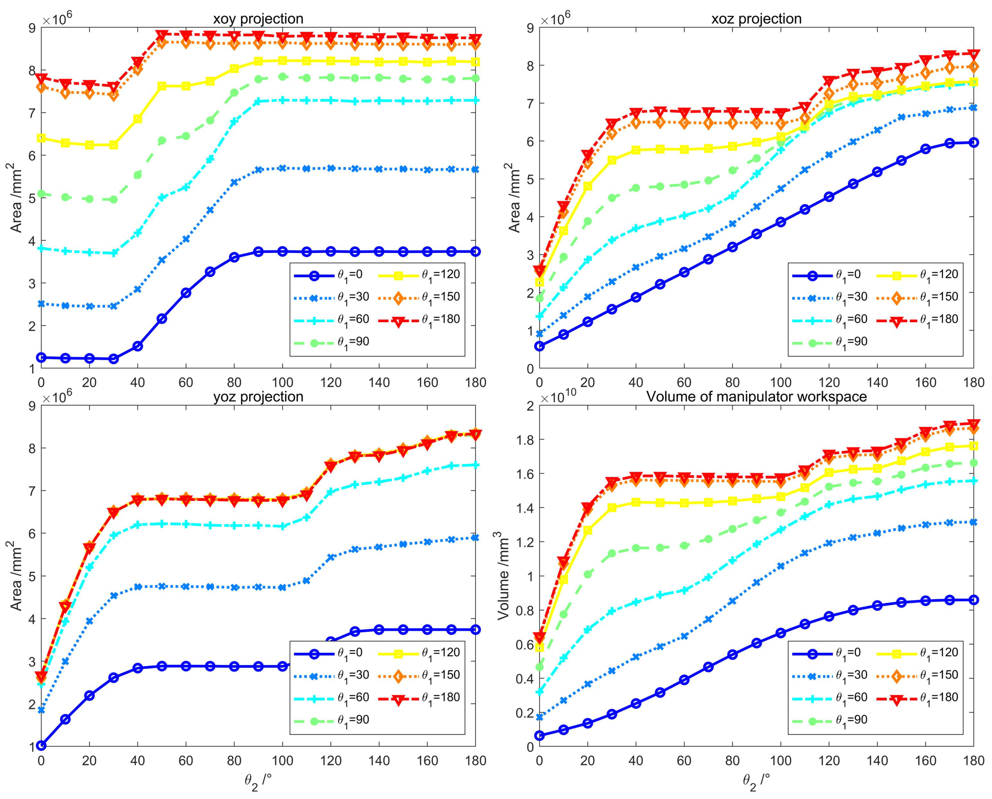
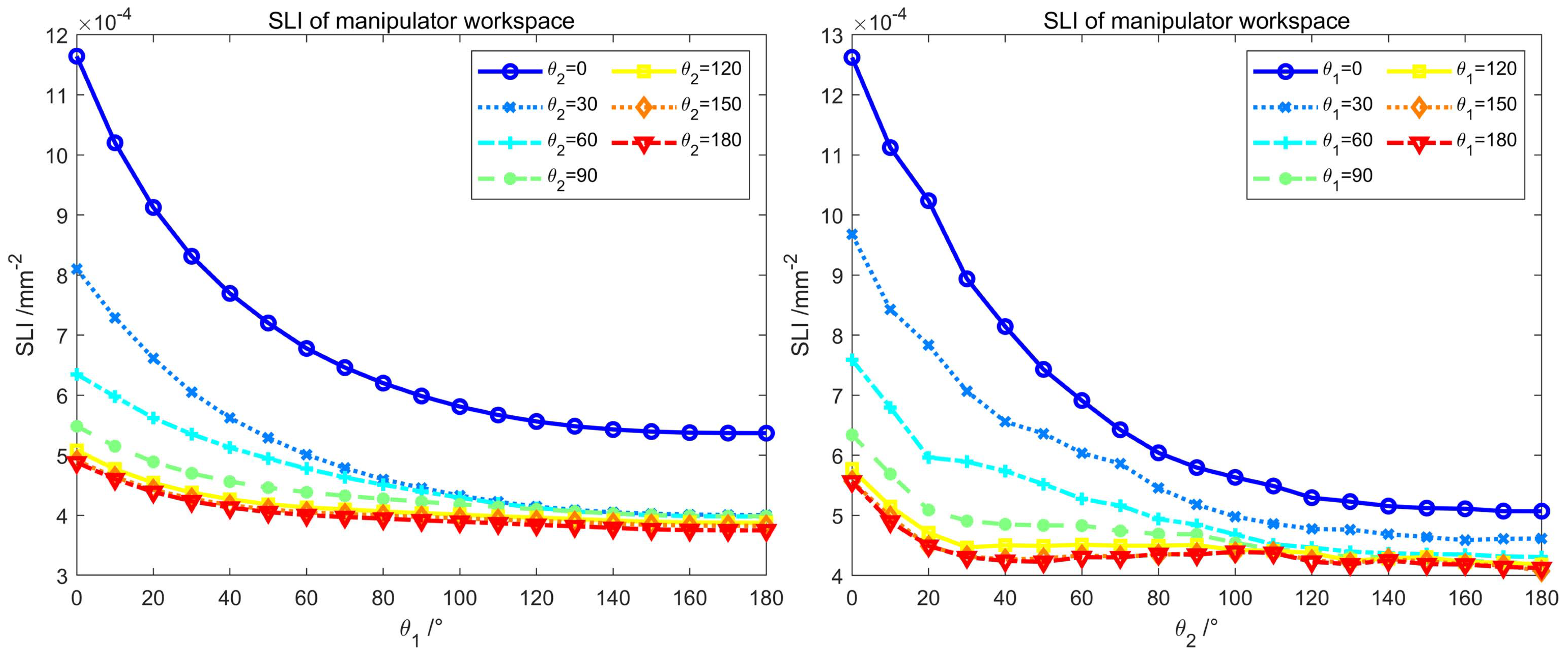
As shown in Figure 3, when θ 1 = 90 , θ 2 = 60 , the workspace of the SRM has reached 76.3 % of the maximum θ 1 = 180 , θ 2 = 180 . And its workspace in the yoz projection has reached its maximum value as shown in Figure 3c. As illustrated in Figure 4, the SLI value is not optimal at this point. But the joint angle, structural complexity, and working performance are balanced; i.e., the joint angle and structural complexity are reduced while working performance is achieved. Therefore, θ 1 = 90 and θ 2 = 60 is a cost-effective solution that meets the basic requirements.

4.3. Global Condition Index of the Manipulator

Manipulators designed with the maximization of workspace in mind may exhibit undesirable kinematic properties [34]. To avoid these issues, we employ dexterity to evaluate the robot arm’s working space. To evaluate the dexterity of a robotic arm, there is no one criterion. One of the most used evaluation metrics is the inverse of the Jacobi matrix condition number 1 / K j . It is expressed as follows.
1 K J = 1 J J 1
where J denotes a Jacobi matrix, and J 1 denotes the inverse of J. The larger the ratio of 1 / K J , the more dexterous the robot arm. In contrast, the arm’s dexterity decreases as the 1 / K J value decreases.
Equation (15) shows that 1 / K J is only determined by the Jacobi matrix, which varies with the position of the arm. Therefore, 1 / K J can only measure the dexterity of one point in the workspace but not the dexterity of all points in the workspace as a whole, and it is only a limited evaluation indicator.
A Global Condition Index (GCI) was introduced by Gosselin [35] to evaluate the dexterity of a manipulator. GCI allows the evaluation of the full workspace of the manipulator. The corresponding equation is provided below.
G J = W 1 / K J d W W d W
where W 1 / K J d W denotes the integral of the inverse of the condition number of the Jacobi matrix over the reachable workspace, and W d W denotes the volume of the reachable workspace. Equation (16) is based on the inverse of the condition number of the Jacobi matrix, but it provides a comprehensive evaluation of the mechanism’s dexterity throughout the entire workspace. As Equation (16) comprises integral operations and it is difficult to obtain an analytical solution for K J , it is difficult to apply for practical calculations; hence, it has been simplified.
G J = 1 / K J W d W
where 1 / K J denotes the sum of the inverse of the condition number of the Jacobi matrix for all points in the workspace.
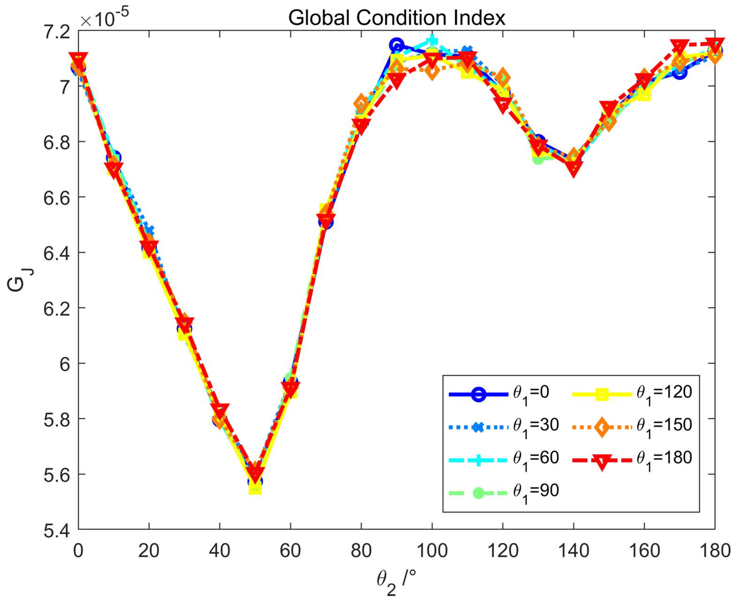
We plotted Figure 5 based on Equation (17). Figure 5 demonstrates that θ 1 has less influence on the dexterity of the robot arm, while θ 2 has more influence.
Combining the workspace planning of Section 2.2, the workspace area and volume of Section 4, and the evaluation of SLI and GCI, we finally chose the solution with θ 1 = 90 , θ 2 = 60 . Noteworthy, the manipulator exhibited the greatest dexterity when θ 2 = 100 in the GCI assessment. Nevertheless, an increase in the value of θ 2 will dramatically increase the robot arm’s size and cost. Taking into account the arm’s workspace area, size, and costs, we have avoided the joint angles where dexterity is at its worst and settled on a compromise of θ 2 = 60 .
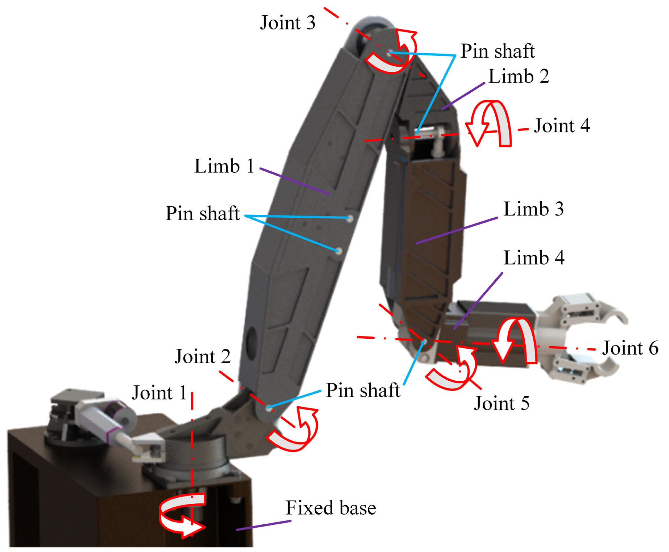
As shown in Figure 6, we have finalized the design of the SRM based on the joint parameters given by the algorithm described above. Figure 6 labels each of the slave hand’s six joints and limbs. Assume that the Cartesian coordinates of the object are [ 1438 , 385 , 250 ] when two manipulators are employed to collaboratively grasp an object in front of them. Using inverse kinematic calculations, the joint angle of the 1# SRM can be set to [ 15 , 20 , 15 , 0 , 18 ] , while the joint angle of the 2# SRM can be set to [ 15 , 20 , 15 , 0 , 18 ] . This set of joint angle settings enables the ends of both robotic arms to just reach the position of the object before performing the picking action.

5. Master-Slave Workspace Design

5.1. Master-Slave Control Systems

Master-slave manipulators can be divided into two types according to whether the structure of the master and slave ends are identical: master-slave isomorphic manipulators and master-slave nonisomorphic manipulators. Master-slave isomorphic robotic arms have the same degrees of freedom and structural design. The SRM merely has to match the MRM’s joint locations to follow it. This method requires all master and slave design characteristics to be similar, and its operation is more intuitive. Using the remote operation flow depicted in Figure 1, the master-slave isomorphic robotic manipulator enables the SRM to operate remotely in complicated and constrained situations. Each joint of the MRMs and SRMs contains an inclination sensor or encoder to capture position and velocity information. The MRM controller is cable-connected to the MRM, while the SRM controller is similarly cable-connected to the SRM. MRM and SRM controllers communicate via wireless signals.
The principal master-slave control flow is depicted in Figure 1. Firstly, the operator controls the MRM and adjusts its position depending on data from monitoring devices attached to the SRM. The red arrows in Figure 1 represent the many operations conducted by the operator on the MRM to prevent the SRM from colliding with obstacles. Then, the MRM controller collects the information from the MRM encoder and transmits it to the SRM controller. Simultaneously, the SRM controller transmits a new position command to the SRM, which collects the SRM’s actual position in real time and transmits it back to the operator through a wireless signal for display.
The above process synchronizes the MRM and SRM positions. Through the MRM, the operator controls the movement of each joint of the SRM, which in turn controls the movement of the entire SRM. In addition, the operator can operate under the real-time conditions of the environment, thereby reducing the risk of collisions and other accidents and allowing obstacle avoidance and safe operation of the robot arm in an unstructured environment.
Remark 1. 
The surrounding environment for robotic arms in confined places is unstructured and filled with obstructions. If the mechanical arm takes the form of a master-slave non-isomorphic case, the motion of the SRM generated by the kinematic inverse solution is not intuitive and cannot be controlled. This makes it difficult for the operator not just to immediately view the SRM’s posture but also to control each of the SRM’s joints. Consequently, if there are barriers in the vicinity of the SRM, the kinematic inverse solution may result in collisions between the SRM and the obstacles. Therefore, a master-slave isomorphic technique not only enables the operator to visually observe the SRM’s posture but also to directly manipulate each joint, hence minimizing collisions between the SRM and its surroundings. Therefore, the master and slave hands in this study have a master-slave isomorphic design, and this paper investigates only the workspace of a master-slave isomorphic manipulator.

5.2. Workspace Design of SRM

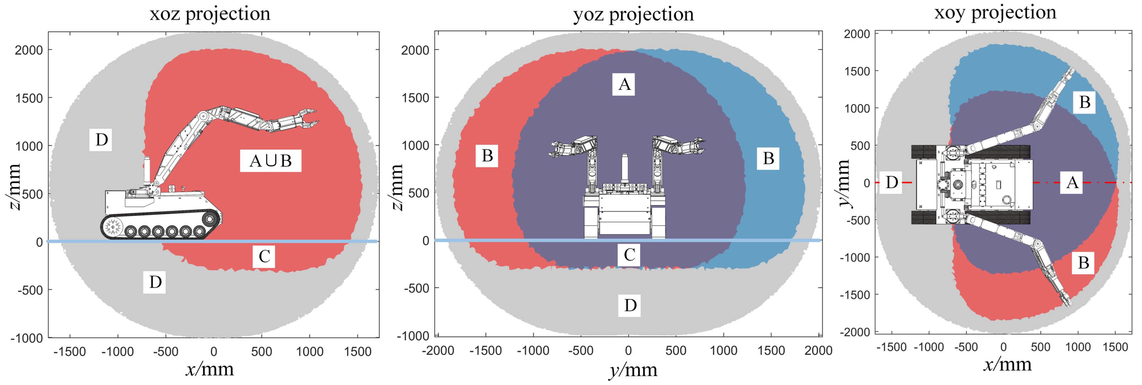
Figure 7 illustrates the workspace of an NPPER’s dual SRMs. The gray areas represent the expanded workspace that the dual SRMs can reach by enhancing the joint angle range. The other colored areas represent the actual workspace that the designed robotic arms can reach by limiting the joint angle range.
In accordance with the preliminary planning of the workspace described in Section 2.2, the NEPRR’s workspace has been divided in detail into four zones. Zone A is a two-arm collaborative workspace where two SRMs can work together. Zone B is the single-arm workspace, where only a single SRM can reach and accomplish a single-arm task. Zone C is the underground workspace, which is utilized in locations where the robot must work beneath the tracked chassis, such as SRMs working in low-lying pits. Zone D is the unused area, which is a workspace that has been abandoned owing to practical task requirements, cost, safety, and hardware constraints.
For a clearer illustration of the 3D envelope of the manipulator workspace, Figure 8 depicts the workspace of a single mechanical arm and its 3D envelope based on the suggested convex hull technique in Section 4.1. As depicted in Figure 7 and Figure 8, the NPPER’s workspace is an ellipse, and this elliptical workspace is directly in front of the robot, corresponding to the required workspace of the NPPER.

5.3. Workspace Design of MRM

The operational MRM’s motion must be translated into motion control directives for the SRM in real time for master-slave control. The master-slave isomorphic manipulator workspace’s outward contours are comparable; therefore, a proportionate mapping approach can be utilized to create the MRM workspace based on the positional connection.
P S = K P P ˜ M
where P S R 1 × 6 and P M R 1 × 6 are the pose vectors of SRM and MRM, respectively. K P R 6 is the mapping matrix of the spatial poses between the MRM and SRM; it describes the relationship between the two arms. K P is the scale mapping matrix of spatial poses between the MRM and the SRM, which is denoted as d i a g ( k x , k y , k z , k α , k β , k γ ) . P ˜ M represents the filtered P M .
By manipulating the MRM, the operator sends motion commands to the SRM. MRM and SRM have different joint ranges and end ranges. Consequently, the real working space of the MRM is modified based on the configuration of the workspace of the SRM. Based on the workspace of the SRM as depicted in Section 5.2, a proportional correction is made to the workspace of the MRM according to the range of motion in each axis. The value of K P is set to d i a g ( 8.3 , 8.8 , 8 , 1 , 1 , 1 ) . According to the OAAS algorithm proposed in Section 3.2 and Equation (18), as depicted in Figure 9, the workspace of the MRM and SRM was determined.
The green area in Figure 9 represents the mapped MRM workspace, while the red area represents the SRM workspace. It can be observed that the SRM’s range of motion is within the MRM’s reach, indicating that the SRM can execute any motion command from the MRM and meet master-slave control performance requirements.

6. Conclusions

This research introduces a new methodology for quantitative analysis of the workspace of robotic arms, which establishes the foundation for the design, analysis, comparison, and evaluation of the workspace of the dual manipulators of NPPERs. Based on the Monte Carlo approach, the OAAS algorithm is proposed to handle the problem of non-uniform and unclear workspace boundaries; the convex hull technique for determining the three-dimensional envelope of the workspace is proposed, and the volume of the envelope can be precisely determined. After a comparative analysis of the workspace’s two-dimensional projection, volume, SLI and GCI values, as well as the robot’s task requirements, we obtained a workspace that satisfies the task requirements. Thus, the optimal parameters for NPPERs were established. Moreover, we acquired the workspace of the MRM that corresponds to the workspace of the SRM through master-slave workspace mapping. Finally, we acquired the dual master-slave manipulator workspace based on the mission requirements of the NPPER. The results demonstrate that the suggested OAAS technique can accurately display the manipulator’s workspace, resolving the Monte Carlo method’s drawbacks of uneven density and unclear workspace boundary; the proposed convex hull algorithm can efficiently obtain the workspace’s three-dimensional envelope. In addition, the approach presented for a quantitative study, comparison, and evaluation of workspaces provides theoretical support for the selection and optimization of structural characteristics for NPPERs. Subsequently, we will examine the master-slave control of the manipulator to accomplish the effective operation of the master-slave manipulator in a confined environment.

Author Contributions

Conceptualization, Y.S.; methodology Y.S. and X.L.; software, Y.S.; supervision Y.W. and H.M. All authors have read and agreed to the published version of the manuscript.

Funding

This work was supported by the National Natural Science Foundation of China (51975336), Key Research and Development Program of Shandong Province (2020JMRH0202), Major Industrial Research Projects in Shandong Province for the Conversion of Old and New Kinetic Energy (2021-13), Key Research and Development Project of Jining City (2021DZP005), and Shandong Provincial Key R&D Program (2022CXGC020701).

Data Availability Statement

Data available on request due to restrictions. The data presented in this study are available on request from the corresponding author. The data are not publicly available due to restrictions.

Conflicts of Interest

The authors declare no conflict of interest.

References

  1. Dong, M.; Li, J.; Chou, W. Depth control of ROV in nuclear power plant based on fuzzy PID and dynamics compensation. Microsyst. Technol. 2020, 26, 811–821. [Google Scholar] [CrossRef]
  2. Cho, B.H.; Byun, S.H.; Shin, C.H.; Yang, J.B.; Song, S.I.; Oh, J.M. KeproVt: Underwater robotic system for visual inspection of nuclear reactor internals. Nucl. Eng. Des. 2004, 231, 327–335. [Google Scholar] [CrossRef]
  3. Fu, X.; Yan, G.; Yan, B.; Liu, H. A new robot system for auto-inspection of intersected welds of pipes used in nuclear power stations. Int. J. Adv. Manuf. Technol. 2006, 28, 596–601. [Google Scholar] [CrossRef]
  4. Chen, Z.; Wu, H.; Chen, Y.; Cheng, L.; Zhang, B. Patrol robot path planning in nuclear power plant using an interval multi-objective particle swarm optimization algorithm. Appl. Soft Comput. 2022, 116, 108192. [Google Scholar] [CrossRef]
  5. Zhonglin, Z.; Bin, F.; Liquan, L.; Encheng, Y. Design and function realization of nuclear power inspection robot system. Robotica 2021, 39, 165–180. [Google Scholar] [CrossRef]
  6. Nagatani, K.; Kiribayashi, S.; Okada, Y.; Otake, K.; Yoshida, K.; Tadokoro, S.; Nishimura, T.; Yoshida, T.; Koyanagi, E.; Fukushima, M.; et al. Emergency response to the nuclear accident at the Fukushima Daiichi Nuclear Power Plants using mobile rescue robots. J. Field Robot. 2013, 30, 44–63. [Google Scholar] [CrossRef]
  7. Kim, I.S.; Choi, Y.; Jeong, K.M. A new approach to quantify safety benefits of disaster robots. Nucl. Eng. Technol. 2017, 49, 1414–1422. [Google Scholar] [CrossRef]
  8. Otaki, M. Environmental monitoring robots for nuclear emergencies. Adv. Robot. 2002, 16, 501–504. [Google Scholar] [CrossRef]
  9. Chengze, L.; Zhi, Y.; Jingshan, D.; Baojun, Z.; Lei, G. Study on accident response robot for nuclear power plant and analysis of key technologies. Chin. J. Nucl. Sci. Eng. 2013, 33, 97–105. [Google Scholar]
  10. Han, Y.; Luan, W.; Jiang, Y.; Zhang, X. Protection of electronic devices on nuclear rescue robot: Passive thermal control. Appl. Therm. Eng. 2016, 101, 224–230. [Google Scholar] [CrossRef]
  11. Kim, J.S.; Jang, Y.H. Development of stable walking robot for accident condition monitoring on uneven floors in a nuclear power plant. Nucl. Eng. Technol. 2017, 49, 632–637. [Google Scholar] [CrossRef]
  12. Kim, D.; Kim, Y.S.; Noh, K.; Jang, M.; Kim, S. Wall-climbing robot with active sealing for radiation safety of nuclear power plants. Nucl. Sci. Eng. 2020, 194, 1162–1174. [Google Scholar] [CrossRef]
  13. Yin, G.; Fuying, H.; Li, Z.; Ling, J. Workspace description and simulation of a backhoe device for hydraulic excavators. Autom. Constr. 2020, 119, 103325. [Google Scholar] [CrossRef]
  14. Merlet, J.P. Parallel Robots; Springer Science & Business Media: Berlin/Heidelberg, Germany, 2005; Volume 128. [Google Scholar]
  15. Bohigas, O.; Manubens, M.; Ros, L. A complete method for workspace boundary determination on general structure manipulators. IEEE Trans. Robot. 2012, 28, 993–1006. [Google Scholar] [CrossRef] [Green Version]
  16. Liu, X.J.; Wang, J. Parallel Kinematics; Springer Tracts in Mechanical Engineering; Springer: Berlin/Heidelberg, Germany, 2014. [Google Scholar]
  17. Guan, Y.; Yokoi, K. Reachable space generation of a humanoid robot using the monte carlo method. In Proceedings of the 2006 IEEE/RSJ International Conference on Intelligent Robots and Systems, Beijing, China, 9–15 October 2006; pp. 1984–1989. [Google Scholar]
  18. Guan, Y.; Yokoi, K.; Zhang, X. Numerical methods for reachable space generation of humanoid robots. Int. J. Robot. Res. 2008, 27, 935–950. [Google Scholar] [CrossRef]
  19. Pisla, D.; Szilaghyi, A.; Vaida, C.; Plitea, N. Kinematics and workspace modeling of a new hybrid robot used in minimally invasive surgery. Robot. Comput.-Integr. Manuf. 2013, 29, 463–474. [Google Scholar] [CrossRef]
  20. Burgner-Kahrs, J.; Gilbert, H.B.; Granna, J.; Swaney, P.J.; Webster, R.J. Workspace characterization for concentric tube continuum robots. In Proceedings of the 2014 IEEE/RSJ International Conference on Intelligent Robots and Systems, Chicago, IL, USA, 14–18 September 2014; pp. 1269–1275. [Google Scholar]
  21. Badescu, M.; Mavroidis, C. New performance indices and workspace analysis of reconfigurable hyper-redundant robotic arms. Int. J. Robot. Res. 2004, 23, 643–659. [Google Scholar] [CrossRef]
  22. Rastegar, J.; Fardanesh, B. Manipulation workspace analysis using the Monte Carlo method. Mech. Mach. Theory 1990, 25, 233–239. [Google Scholar] [CrossRef]
  23. Alciatore, D.G.; Ng, C.C.D. Determining manipulator workspace boundaries using the Monte Carlo method and least squares segmentation. In Proceedings of the International Design Engineering Technical Conferences and Computers and Information in Engineering Conference. American Society of Mechanical Engineers, Minneapolis, MN, USA, 11–14 September 1994; Volume 12860, pp. 141–146. [Google Scholar]
  24. Wang, L.; Wu, J.; Tang, D. Research on workspace of manipulator with complicated constraints. In Proceedings of the 2008 7th World Congress on Intelligent Control and Automation, Chongqing, China, 25–27 June 2008; pp. 995–999. [Google Scholar]
  25. Liu, Z.; Liu, H.; Luo, Z.; Zhang, X. Improvement on Monte Carlo method for robot workspace determination. Nongye Jixie Xuebao (Trans. Chin. Soc. Agric. Mach.) 2013, 44, 230–235. [Google Scholar]
  26. Cao, Y.; Lu, K.; Li, X.; Zang, Y. Accurate numerical methods for computing 2d and 3d robot workspace. Int. J. Adv. Robot. Syst. 2011, 8, 76. [Google Scholar] [CrossRef] [Green Version]
  27. Peidró, A.; Reinoso, Ó.; Gil, A.; Marín, J.M.; Payá, L. An improved Monte Carlo method based on Gaussian growth to calculate the workspace of robots. Eng. Appl. Artif. Intell. 2017, 64, 197–207. [Google Scholar] [CrossRef]
  28. Cao, Y.; Qi, S.; Lu, K.; Zang, Y.; Yang, G. Shape and size computation of planar robot workspace. In Proceedings of the 2009 WRI World Congress on Computer Science and Information Engineering, Los Angeles, CA, USA, 31 March–2 April 2009; Volume 2, pp. 126–130. [Google Scholar]
  29. Bader, A.M.; Maciejewski, A.A. A hybrid approach for estimating the failure-tolerant workspace size of kinematically redundant robots. IEEE Robot. Autom. Lett. 2020, 6, 303–310. [Google Scholar] [CrossRef]
  30. Hoover, R.C.; Roberts, R.G.; Maciejewski, A.A.; Naik, P.S.; Ben-Gharbia, K.M. Designing a failure-tolerant workspace for kinematically redundant robots. IEEE Trans. Autom. Sci. Eng. 2014, 12, 1421–1432. [Google Scholar] [CrossRef]
  31. Wang, S.; Chen, Z.; Li, J.; Wang, J.; Li, J.; Zhao, J. Flexible motion framework of the six wheel-legged robot: Experimental results. IEEE/ASME Trans. Mechatronics 2021, 27, 2246–2257. [Google Scholar] [CrossRef]
  32. Kohlbrecher, S.; Stryk, O.V. From RoboCup Rescue to supervised autonomous mobile robots for remote inspection of industrial plants. KI-Künstliche Intell. 2016, 30, 311–314. [Google Scholar] [CrossRef]
  33. Patel, S.; Sobh, T. Manipulator performance measures-a comprehensive literature survey. J. Intell. Robot. Syst. 2015, 77, 547–570. [Google Scholar] [CrossRef] [Green Version]
  34. Zhang, D.; Wei, B. Modelling and optimisation of a 4-DOF hybrid robotic manipulator. Int. J. Comput. Integr. Manuf. 2017, 30, 1179–1189. [Google Scholar] [CrossRef]
  35. Gosselin, C.; Angeles, J. A global performance index for the kinematic optimization of robotic manipulators. J. Mech. Des. 1991, 113, 220–226. [Google Scholar] [CrossRef]
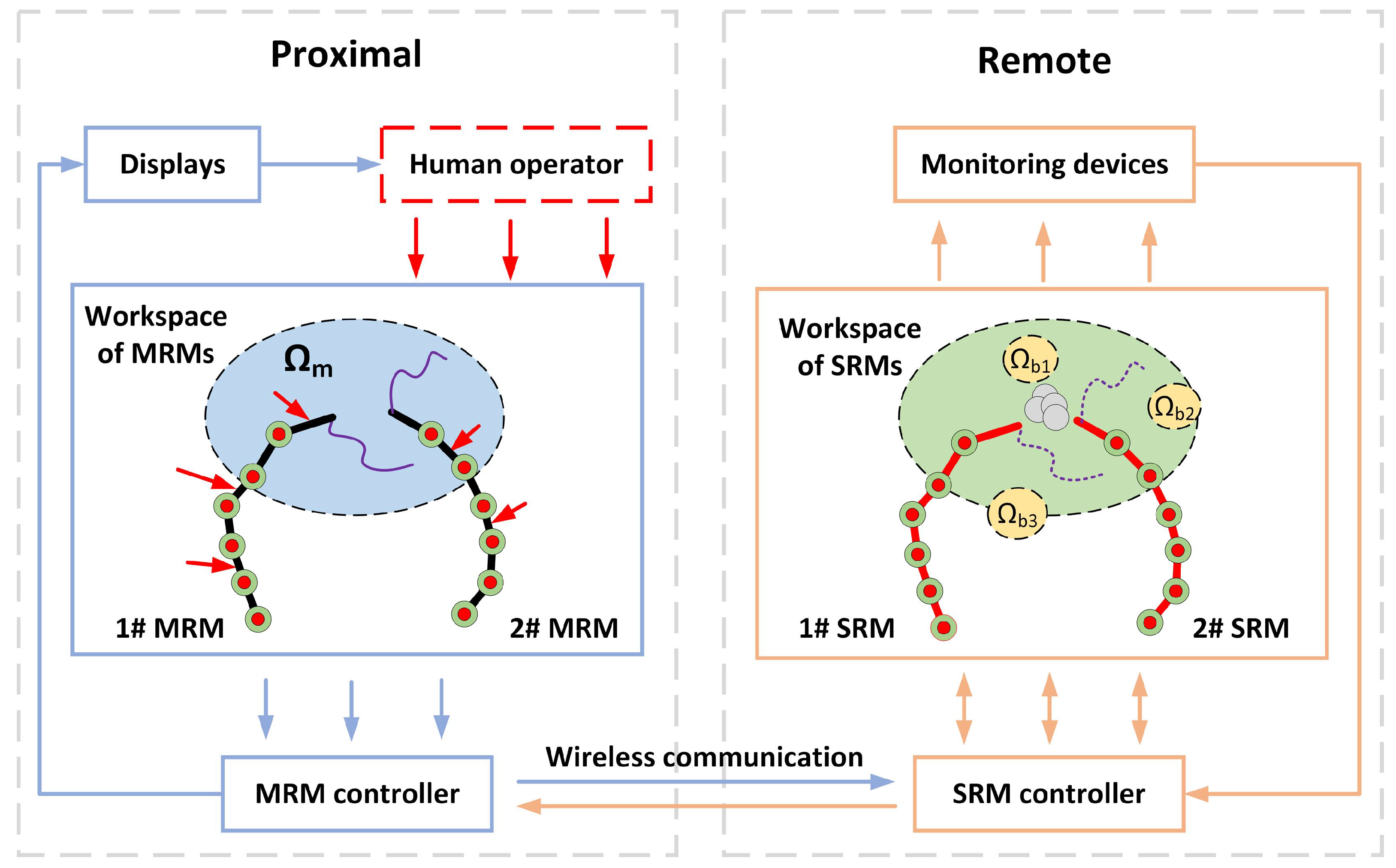
Figure 1. Master-slave configuration.
Actuators 12 00009 g001
Figure 2. Workspaces generated by different algorithms: (a) the Monte Carlo (b) the OAAS.
Actuators 12 00009 g002
Figure 3. Workspace area and volume generated by different joint angles.
Actuators 12 00009 g003
Figure 4. SLI values for different joint angles.
Actuators 12 00009 g004
Figure 5. GCI values for different joint angles.
Actuators 12 00009 g005
Figure 6. Diagram of the manipulator structure of an NPPER.
Actuators 12 00009 g006
Figure 7. Workspace for an NPPER.
Actuators 12 00009 g007
Figure 8. Three-dimensional envelope of the workspace.
Actuators 12 00009 g008
Figure 9. Master-slave workspace matching diagram.
Actuators 12 00009 g009
Disclaimer/Publisher’s Note: The statements, opinions and data contained in all publications are solely those of the individual author(s) and contributor(s) and not of MDPI and/or the editor(s). MDPI and/or the editor(s) disclaim responsibility for any injury to people or property resulting from any ideas, methods, instructions or products referred to in the content.