Abstract
The variable stiffness of robot joints plays an important role in improving the robot’s compliance, safety, and energy efficiency. In this paper, a novel type of variable stiffness joint based on a rack and pinion structure (VSJ-RP) is proposed. The structure and the variable stiffness principle of the joint are described in detail. The theoretical stiffness calculation and the dynamic model of the joint are established, and the correctness of the model is validated by simulation. The compliance, safety, energy storage, and release characteristics of the joint are validated by position, bearing capacity, hitting ball, and safety detection experiments, respectively. These experimental results show that the joint stiffness can be adjusted from 14.74 Nm/rad to 726.58 Nm/rad, and the overshoot of the position response is about 5.56–0.5%. The larger the stiffness of the joint, the faster the adjustment response, the smaller the fluctuation, and the more stable the operation are. The maximum output torque of the joint is about 20 Nm, and the torque difference between the minimum and the maximum stiffness of the joint is about 10%. The energy conversion efficiency of the joint is 17.56%~89.86%, and the deformation angle range is 2.66°~4.37°. These phenomena reflect the safety, energy storage, and release capacity of the joint. An effective exploration is performed regarding the miniaturization, safety, and energy utilization of robot variable stiffness joints.
1. Introduction
Recently, with the increasing demand for physical human–robot interaction (pHRI), compliant joints that can improve the safety and adaptability of the interaction process have attracted more and more attention [1]. In general, compliant joints are used to improve the safety of pHRI or the dynamical adaptability to the environment, as well as enhancing the energy efficiency [2]. Rigid joints have a strong positioning and bearing capacity, but they lack compliance and shock absorption due to the rigid structure of the joint [3]. In complex environment, robots with rigid joints inevitably collide with people and surrounding objects. Thus, they are prone to trigger safety accidents and cause fatal injuries [4].
In order to enhance the compliance and energy storage capacity of robot joints, they are usually designed as variable stiffness structures [5,6]. Chinese and foreign scholars have conducted related research. They have proposed various designs and control algorithms [7,8,9]. Sugar et al. designed an ankle–foot orthotic [10], and Samuel et al. designed a variable stiffness ankle–foot prosthesis [11]. The principle is to add elastic elements at the place where the sole of the foot contacts the ground and the ankle, which is driven by the motor to achieve stiffness control. They are mainly used in prostheses. Matteo et al. proposed a small variable stiffness mechanism [12]. The mechanism can independently change the output stiffness and achieve a change in stiffness from zero to near infinity by changing the pivot point position and the internal spring to the output transmission ratio. It had a large torque output, light mass, and compact structure. It is suitable for the fields of robotics and biomechanics. The vsaUT-II designed by Stefan S. Groothuis et al. uses the variable stiffness of the moving pivot position in the variable stiffness mechanism through a series spring [13]. The pivot position is realized by a planetary gear transmission mechanism. The structure of the vsaUT-II is very compact, but the adjustable range of the joint output stiffness is limited, which cannot provide an adjustable range of joint output stiffness from zero to infinity. Guo et al. designed a novel compliant differential shape memory alloy (shape memory alloy) actuator with two antagonistic SMA wires and a torsion spring, which can realize a higher response and a larger output angle than conventional differential SMA actuators [14]. Schutter proposed a general active flexible motion control method [15], studied the control method of a rigid manipulator through external sensor feedback, and effectively controlled the speed and output force, but the position control accuracy was not high. Lee Y T et al. used the position estimation algorithm to evaluate the accurate position of the hand and the active stiffness control algorithm to control the fingertip force to control the coupling-tendon-driven manipulator, so that the manipulator obtained good linear stiffness characteristics [16]. Yanlei Shi et al. designed a flexible joint with active–passive variable stiffness [17]. The joint has two variable stiffness methods, which use cams and trapezoidal screws to change the spring compression to achieve stiffness adjustment, respectively. Additionally, the joint has a complex structure, large size, and difficult control. Wei Guo used the principle of leverage [18] (i.e., the position of the fulcrum end remains unchanged and the position of the load changes). The radial motion of the slider is transformed into mutual rotation between two discs of the radial groove and the spiral groove. The joint is compact and novel in form, but the range of stiffness change is limited.
Summarizing the previous studies, there are four main methods to change the joint stiffness: (1) series and parallel elastic elements: by detecting the deformation of the elastic component in real-time, the force control problem can be transformed into a position control problem [19,20]; (2) using special materials to achieve joint compliance: the research technology of the joint intersects with new materials such as piezoelectric, magnetic fluid, rubber, thermal fluid, and magnets to achieve joint compliance, but this method has special requirements for the application environment and has certain limitations [21,22]; (3) force control: this method mainly adopts algorithms such as hybrid force position control and impedance control, but these two algorithms are limited by the accuracy of the force sensor and the bandwidth of the control system; in addition, this method also consumes much energy [23]; (4) mechanical variable stiffness: at present, this method is the most concentrated field of research; it can be generally divided into four forms: antagonistic, structural change, mechanical adjustment, and hybrid [24,25].
The performance of the variable stiffness joint is related to the force of the variable stiffness component [26]. In summary, the disadvantages of the above research are as follows: (1) The joint structure is complex and takes up a large space. When maintaining a constant stiffness, the requirement for the stability of the motor is high, which reduces the energy utilization of the joint. (2) The range of the joint variable stiffness is limited. (3) The variable stiffness structure of the joint has a large force variation, a single force position, and a complex control. In order to overcome the above limitations, this paper adopts the fourth method mentioned above (i.e., using mechanical methods to change the stiffness of the joint) to achieve joint variable stiffness. The mechanical structure uses a mechanism based on a rack, pinion, and spring mechanism. The designed variable stiffness joint has the characteristics of a compact structure and simple control. Under a finite force, the joint has a wide range of variable stiffness. The variable stiffness structure of the joint is affected by three forces, and the direction is symmetrically distributed, so that the force of the joint part is uniform and stable.
In this paper, the control of the VSJ-RP is realized by two motors (i.e., joint driving motor and stiffness adjusting motor). The advantage is that independent or composite control can be used. The VSJ-RP can flexibly adjust the best matching stiffness according to the real-time change of the load. The schematic diagram of the joint system is shown in Figure 1. The VSJ-RP has the characteristics of real-time control stiffness, which enhances the adaptability of pHRI.
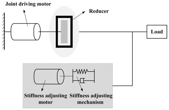
Figure 1.
Schematic diagram of the mechanism’s system.
The subsequent work of this paper is as follows:
- (1)
- In the second part of the paper, the overall structure and the variable stiffness structure of the VSJ-RP are introduced. Based on the variable stiffness principle, the stiffness mathematical model of the VSJ-RP is derived;
- (2)
- In the third part of the paper, the VSJ-RP dynamic model is constructed, and the VSJ-RP system is simulated in MATLAB/Simulink;
- (3)
- In the fourth part of the paper, the VSJ-RP experimental platform is built, and the compliance, safety, and energy storage and release characteristics of the variable stiffness joint are verified by a location experiment, a torque test experiment, a hitting ball experiment, and a security test experiment, respectively.
- (4)
- The fifth part is the conclusion of this paper.
2. Mechanical Structure of the VSJ-RP
2.1. The Overall Structure of the VSJ-RP
The overall structure of the VSJ-RP proposed in this paper is shown in Figure 2. The VSJ-RP contains a joint driving motor, a stiffness-adjusting motor, a reducer, a swinging hand, a synchronous belt, and a stiffness-adjusting mechanism. In order to obtain sufficient torque, the joint driving motor is output through the reducer and the reducer is connected with the synchronous belt to drive the swinging hand. The stiffness-adjusting motor is connected with the pinion. The deformation of the elastic element is controlled by the kinematic characteristics of the rack and pinion mechanism, so as to control the stiffness change of the joint. The VSJ-RP’s parameters are shown in Table 1.
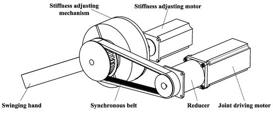
Figure 2.
The overall structure of the VSJ-RP.

Table 1.
Joint parameters.
2.2. Mechanical Structure of Stiffness-Adjusting Mechanism
The variable stiffness mechanism composing the joint is shown in Figure 3. The module consists of a shell, three elastic element covers, three racks, three elastic elements, a center pinion, a support block, three rack sliders, a pinion shaft, a rolling bearing, and a support plate. The base support plate is used to support the rack to ensure the installation accuracy. The elastic element shell plays a guiding role and has the function of dust prevention.
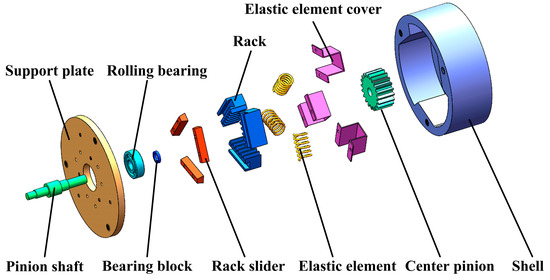
Figure 3.
The structure diagram of the stiffness-adjusting mechanism.
The installation between them is as follows: the pinion shaft and support plate are connected together by the rolling bearing. The support block is used to locate the rolling bearing and is installed on the pinion shaft. A threaded connection is adopted between the rack slider and support plate. The groove surface on the rack is in contact with the surface of the rack slide, and the rack can move on the rack slide. The elastic element is placed in the elastic element cover, and one end of it is in contact with the rack, while the other end is in contact with the plane of the shell. The center pinion adopts an interference fit to the gear shaft.
The shell of the stiffness-adjusting mechanism is designed as a specially shaped structure, as shown in Figure 4. Three planes with a wide enough area are designed inside the shell to make full contact with the spring and share the stress on the spring. There are three threaded holes on the shell to connect with the support plate, and the other side of the shell has threaded holes to connect to the swinging hand.
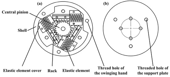
Figure 4.
The structure diagram of the shell of the stiffness-adjusting mechanism: (a) front of the shell and (b) back of the shell.
2.3. The VSJ-RP Mathematical Model
In order to facilitate the analysis, the stiffness was analyzed by using the diagram of the stiffness-adjusting mechanism. The specific simplified diagram is shown in Figure 5.
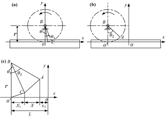
Figure 5.
Schematic diagram of the mechanism: (a) center pinion before motion, (b) center pinion after motion, and (c) schematic diagram of the angle change.
The main movement of the VSJ-RP can be concentrated on the center pinion, rack, and elastic element. Therefore, the Cartesian coordinate system is established on the rack. In Figure 5a,b, respectively, represent the state of the central pinion before and after rotation. In Figure 5a, the circle B represents the central pinion, and the x-axis represents the rack. is the initial joint angle. Point C is the initial position corresponding to . Where r is the radius of the gear reference circle. In Figure 5b), is the relative rotation angle of the pinion, and point A is the position corresponding to . In Figure 5c, L is the displacement determined by , X1 is the displacement determined by , xA is the abscissa of point A, and X is the deformation of the spring. In Figure 5a, the parameter equation of the moving gear circle at any time is obtained for parameter as follows::
According to the integral definition of the arc length, we can obtain:
Point A is obtained by rotating on the circle and substituting it into the parametric equation; we can obtain:
According to Figure 5c, we can obtain:
The force diagram of the shell is shown in Figure 6.
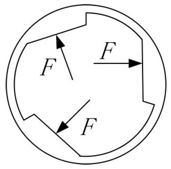
Figure 6.
The force diagram of the shell.
Therefore, the magnitude of the single force F experienced on the shell is:
where k is the spring coefficient and X is the deformation of the spring. Therefore, the torque of a single force F is:
where T is the moment provided by a single force and L1 is the moment of the arm; its length is: , where m is the module of the pinion, z is the number of teeth, and b is the rack thickness. Since the whole joint is subjected to forces in three directions, the total load torque is:
Equations (1)–(7) can be combined to obtain:
For the torque:
where KT is the system stiffness. Combined with the constraint conditions’ Equations (1)–(9), we can obtain:
As we can see from (10), we can know that:
- (1)
- The load torque and the stiffness characteristics of the VSJ-RP are mainly determined by the spring type, pinion, and rack parameters. Therefore, different stiffness component types can meet different requirements;
- (2)
- After the parameters of the spring and pinion of the VSJ-RP are determined, the stiffness is mainly affected by the deformation of the spring and the offset angle of the joint.
3. Dynamics Analysis of the VSJ-RP
3.1. The VSJ-RP’s Dynamics Model
Dynamic analysis is a key step in the study of the variable stiffness joint. Its accuracy directly affects the characteristics of the joint system [27]. The VSJ-RP can be considered as equivalent to a variable spring, as shown in Figure 7. The stiffness value changes with the input and output states of the joint.
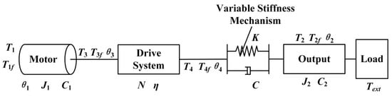
Figure 7.
Simplified dynamics model.
Table 2 describes the meanings of the parameters in the figure.
Table 2.
Parameter meanings of the simplified joint model.
It can be seen from Figure 7 that the torques at both ends of the variable stiffness joint have the following relationship:
According to Newton’s second law, there is the following relationship between the motor and the load end:
However, the output angle and torque of the drive system have the following relationship with the output angle and torque of the main motor:
Ignoring the friction loss in the system and substituting:
The Laplace transform gives:
3.2. Dynamics Simulation of the VSJ-RP
From the above equation, the MATLAB/Simulink visualization block diagram can be established as follows (as shown in Figure 8). When the joint load is zero, the step signal of the given driving torque is T1 = 5 Nm, and the response curves of the output angle, angular velocity, and torque of the joint are observed under different stiffness conditions. The analysis results are shown in Figure 9, Figure 10 and Figure 11.
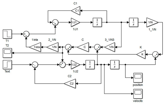
Figure 8.
The visualization block diagram of the VSJ-RP.
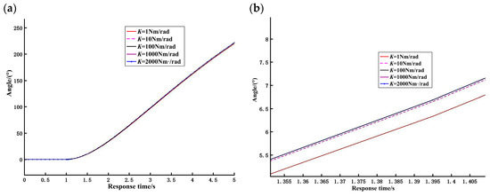
Figure 9.
Simulation output angle curve: (a) original diagram of output angle curve and (b) local enlarged curve of output angle.
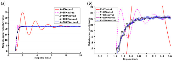
Figure 10.
Simulation output angular velocity response curve: (a) original diagram of output angular velocity response curve and (b) local enlarged curve of output angular velocity.
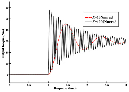
Figure 11.
Output torque response curve.
It can be seen from the angle curve in Figure 9 that the joint output angle increases linearly from zero as a whole. Within 5 s, the output angle can reach 230°; there is fluctuation in the initial stage, and the whole curve is smooth. The results show that the designed VSJ-RP has a large range of angle variation and good output stability.
The joint output angular velocity curve is shown in Figure 10. The joint output angular velocity also increases slowly from zero. After a period of time, it can reach a stable speed and remain unchanged. However, due to the certain compliance of the spring, the whole process will fluctuate. When the joint is in different stiffness output states, the dynamic response of the system is different. In the case of low stiffness, the response velocity of the system is relatively slow, the response time required to achieve stability is relatively long, and the fluctuation of the response curve is relatively obvious. When the joint is in a state of high output stiffness, the response time is relatively short, the response velocity is relatively fast, and the fluctuation amplitude of the response curve is weak.
In summary, the simulation results verified that the VSJ-RP has variable stiffness characteristics and the joint shows different response characteristics for different stiffness output values, which can be applied to meet different requirements.
Next, the step signal with a given driving torque T1 = 5 Nm was analyzed. When the load is Text = 30 Nm, the response curve of the joint output torque with time under different stiffness states is shown in Figure 11.
It can be seen from the curve in the figure that, when there is load input, the joint output torque increases from zero. At the beginning, it presents an oscillation waveform, which is approximately constant at the stable load torque; however, the whole process shows relatively large fluctuations, and the amplitude and bandwidth of the oscillation waveform are different with the different stiffness. Specifically, when the joint output stiffness is relatively small, the output torque fluctuates greatly, and it takes a long time to reach the stable state. With the increase of the joint stiffness, the fluctuation of the torque becomes smaller; however, the response speed does not change significantly, and a large overshoot occurs. On the whole, when the joint load is Text = 30 Nm, the output torque of the joint almost reaches 30 Nm. Therefore, the simulation results show that the output load of the joint can also meet the requirements of the joint torque of a general miniaturized industrial robot and humanoid robot.
4. Experimental Analysis the VSJ-RP Prototype
4.1. The Construction of the Experimental Platform
The VSJ-RP experimental platform is shown in Figure 12. The experimental platform includes a joint body (i.e., the experimental object), a computer, an STM32 microcontroller, two stepper motors, two motor drivers, a 24 V switching power supply, a voltage regulator, a reducer, and an incremental encoder. The software includes the Kiel5 programming software and a serial communication debugger. These hardware and software devices can measure the position and velocity information of the joint output and transmit it to a PC for processing. The parameters of the VSJ-RP are shown in Table 1.
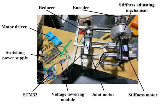
Figure 12.
The VSJ-RP experimental platform.
4.2. Joint Stiffness Characteristics’ Verification Experiment
Through the above parameters, the motor can be controlled and adjusted to rotate at different angles. At each rotation angle position, the load size is gradually changed. The offset angle of each position is measured by the encoder, and then, the stiffness value of different rotation angles is obtained by calculation. The theoretical curve of the joint and the image of the actual test are shown in Figure 13.
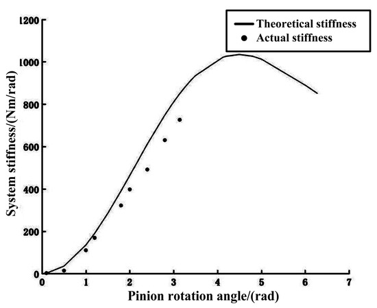
Figure 13.
Change curve of the joint stiffness.
It can be observed in the figure that the measured stiffness changes from 14.74 Nm/rad to 726.58 Nm/rad. With the increase of the angle, it is obvious that the joint has the characteristic of variable stiffness. However, there was some error between the experimental result and the theoretical value of stiffness. With the increase of the stiffness, the error also increased. The largest deviation can reach more than 20%. These errors were mainly caused by machining error, assembly error, measurement accuracy, theoretical calculation, and so on. Therefore, in the process of mechanical structure processing and assembly, the accuracy of the joint should be guaranteed as much as possible, so as to improve the consistency between the measured value of the stiffness and the theoretical value. The experiment also shows that, when the elastic element is compressed forward, the stiffness changes from the beginning to the end from fast to slow. This is caused by the inherent characteristics of the elastic element, the straightness of the mechanical structure, and the friction of each part, which will affect the variable stiffness characteristics of the joint.
4.3. Location Experiment
To verify the motion performance of the VSJ-RP, the joint location experiment was set up: the joint stiffness was adjusted to 14.74 Nm/rad, 364 Nm/rad, and 726.58 Nm/rad, and let the joint rotate 360° before stopping. The angle of the swinging hand can be converted from the pulse value of the encoder. The experimental result is shown in Figure 14.
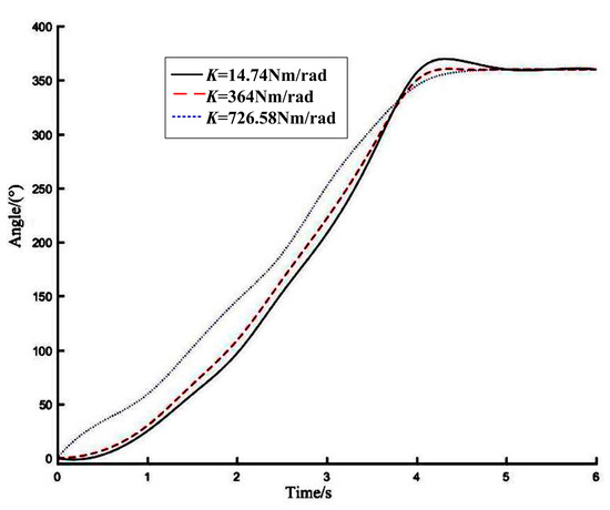
Figure 14.
Joint position curve.
It can be seen from the figure that when the joint stiffness is K = 14.74 Nm/rad, the internal potential energy of the joint is the largest and the kinetic energy is the smallest. The joint adjustment speed is slow, and the overshoot of the joint position is no more than 6%, which is mainly caused by the structure of the elastic elements inside the joint. When the joint stiffness is K = 364 Nm/rad, the overshoot of the joint position is obviously reduced and the adjustment speed is fast. When the joint stiffness is K = 726.58 Nm/rad, the joint position overshoot is small (slightly more than 0.5%), the adjustment speed is fast, and the joint overshoot is good. After the start-up is complete, the joint runs continuously, and the effect of the end output angle is small.
4.4. Torque Test Experiment
In order to reflect the carrying capacity of the VSJ-RP, a torque experiment was used to verify it. The experimental steps were as follows: The joint stiffness was set to 14.74 Nm/rad, 364 Nm/rad and 726.58 Nm/rad, respectively. The motor speed was set as 200 r/min. The time–torque curve is shown in Figure 15. From the figure, we can know the following: from 0–0.7 s, the joint starts and increases the speed, and its output torque decreases sharply; from 0.7–1.4 s, the output torque remains steady; from 1.4 s–2.2 s, the output torque fluctuates; after 2.2 s, it is basically stable and the output torque of the VSJ-RP is about 20 Nm. The difference between the minimum stiffness and the maximum stiffness is about 10%.
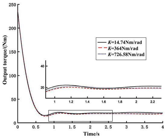
Figure 15.
Time–torque curve.
4.5. Hitting Ball Experiment
In order to further study the characteristics of the VSJ-RP’s energy storage and release, the hitting ball experiment was used to verify it. A table tennis ball was selected as the hitting object, and its mass was 2.79 g. As shown in Figure 16, it was placed on the swinging hand of the joint, the joint was adjusted to different output stiffness, and the table tennis ball hit at the same height each time. Air resistance was ignored in the experiment. The energy utilization rate was converted according to the flat throwing motion (as shown in Figure 17). Equation (16) is the calculation formula of the initial velocity of the ball in the horizontal throwing movement.
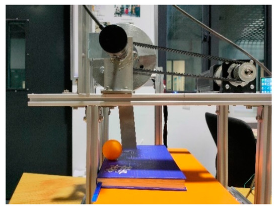
Figure 16.
The prototype platform of the hitting experiment.
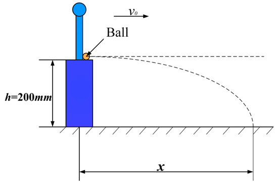
Figure 17.
Schematic diagram of the hitting experiment.
The experimental data are shown in Table 3. The ball hit 10 times at each stiffness value, and 5 groups were randomly selected for the analysis.
Table 3.
Hitting experimental data.
It can be seen from Table 3 that, when the initial conditions are the same, the ball can obtain different initial velocities under the impact of different stiffnesses of the joint. The stiffness–energy utilization curve is shown in Figure 18. The experimental result shows that: (1) When the hitting position is constant (h = 200 mm) and the joint stiffness is K = 14.74 Nm/rad, the ball can obtain the initial velocity v0 = 1.81 m/s. It can obtain the minimum kinetic energy and the shortest flight distance. When the joint stiffness is K = 726.58 Nm/rad, the elastic elements inside the joint will play a greater role. Due to the compliance of the VSJ-RP, a small part of its kinetic energy is transformed into elastic potential energy. The initial velocity of the ball is v0 = 2.59 m/s. The ball obtains the largest kinetic energy, and it will be hit farther. (2) The energy utilization rate of the system = the kinetic energy obtained by the ball/the total input energy of the system. When the joint stiffness is in the AC segment, K = 14.74~364 Nm/rad. Because the elastic element is more prone to deformation, most of the total input energy of the joint is converted into elastic potential energy. It stores and releases more elastic potential energy, and the velocity of the swinging hand increases. Therefore, the energy utilization rate of the joint increases slowly with the increase of the stiffness at this stage. When the stiffness is K = 14.74 Nm/rad, the energy utilization rate is 17.56%. The energy utilization rate of the joint in the CE segment (K = 364~726.58 Nm/rad) increases sharply with the increase of the stiffness. At this stage, the stiffness is greater. The total input energy of the joint is mostly converted into the kinetic energy of the joint. It stores and releases the elastic potential energy, which becomes less. Therefore, the energy characteristics with greater stiffness are more obvious than those with lesser stiffness.
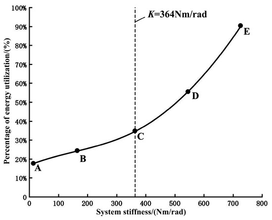
Figure 18.
Stiffness–energy utilization curve.
The experiment shows that the energy utilization rate of the VSJ-RP is high, up to 89.86%. The kinetic energy of the ball comes from the difference between the kinetic energy of the swinging hand and the potential energy stored in the variable stiffness joint. Therefore, the variable stiffness joint in this study was compared with the traditional rigid joint: the variable stiffness joint will have good energy storage and release ability.
4.6. Security Test Experiment
In order to verify whether the VSJ-RP has good safety performance, this was verified by a collision experiment. This experiment evaluated the safety performance of the joint through the deformation angle of the VSJ-RP. The experimental process was as follows: The joint was rotated to 103°, and the air resistance was ignored. The experiment was carried out when the joint stiffness was K1 = 14.74 Nm/rad (minimum), K2 = 364 Nm/rad (intermediate), and K1 = 726.58 Nm/rad (maximum), respectively. At the end of the swinging hand, the 7 N iron block was un free fall at a vertical height of 100 mm from the member, as shown in Figure 19. The deformation angle of the joint is shown in Figure 20. When the joint stiffness is K1, the deformation angle of the joint is 4.37°; when the joint stiffness is K2, the deformation angle is 3.56°; when the joint stiffness is K3, the deformation angle is 2.66°.
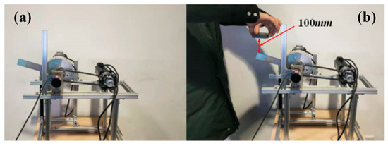
Figure 19.
Free fall percussion experiment: (a) joint position at 103° and (b) iron block initial position.
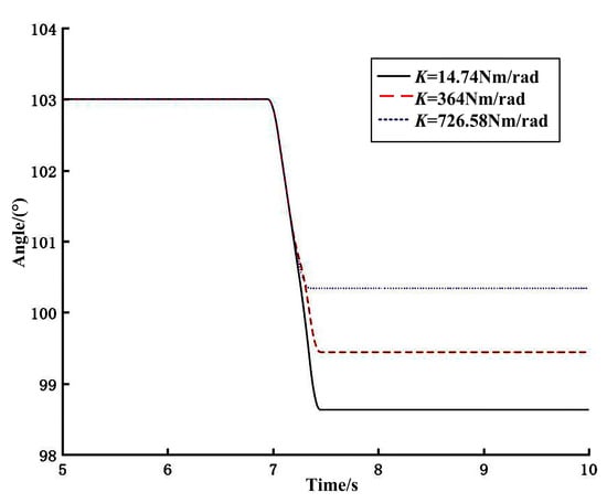
Figure 20.
Deformation angle of the joint position.
It can be seen from Figure 20 that the smaller the joint stiffness is, the greater the joint position deformation is. At this time, the kinetic energy of the joint system is small, the elastic potential energy is large, and the safety factor of the joint in collision is high. When the joint stiffness increases, the joint kinetic energy gradually increases and the elastic potential energy gradually decreases. The joint position deformation angle decreases accordingly. The experimental result shows that, when the joint is suddenly subjected to an external load, the joint has a certain position deformation. When the joint stiffness is smaller, the deformation angle of the joint is larger and the safety of the joint is better. The experiment shows that the designed variable stiffness joint has a good safety performance.
5. Conclusions
In this paper, we proposed a variable stiffness joint based on a rack and pinion mechanism. The joint adopts a three-way symmetrical structure, a pinion, and a spring structure. The stiffness of the joint is changed by controlling the pinion angle. The stiffness theoretical equation of the VSJ-RP was derived, and its stiffness variation and gear angle were obtained (θ2). The spring coefficient k is related to the pinion parameters. The dynamic model of the VSJ-RP was established, and the system was simulated in MATLAB/Simulink. From the simulation results, we can see that the VSJ-RP has a certain response bandwidth and good torque and position-following characteristics.
The experimental results showed that the joint stiffness can be changed by changing the angle of the central pinion. The theoretical stiffness curve was basically consistent with the actual stiffness test value. The joint stiffness range was 14.74~726.58 Nm/rad, and the error between the maximum joint stiffness and the theoretical curve was 20%. This was mainly due to the processing, assembly, and control accuracy of the joint. The experiment also proved that the maximum output torque of the VSJ-RP was about 20 Nm. The VSJ-RP had good position-following characteristics, and the overshoot of position response was about 5.56–0.5%. In addition, the VSJ-RP also had strong energy storage characteristics and safety performance. The energy conversion efficiency of the joint was 17.56–89.86%, and the maximum deformation angle was 4.37°. The structure of the experimental prototype still needs to be improved to make the joint structure more compact and more suitable for practical applications.
Author Contributions
Conceptualization, H.J. and M.L.; methodology, M.L. and Q.H.; validation, H.J., S.L., M.L. and Q.H.; resources, H.J. and Y.L.; experiment. and Q.H.; writing, H.J., M.L., S.L. and Y.L.; funding acquisition, H.J. All authors have read and agreed to the published version of the manuscript.
Funding
This work was supported by the Chongqing Municipal Education Natural Science Foundation (KJQN202001132, KJQN202001127) and Cooperation projects between universities in Chongqing and affiliated institutions of the Chinese Academy of Sciences (HZ2021011).
Data Availability Statement
The research simulation and experimental data of our paper can be reflected in the pictures and tables in the manuscript. Therefore, no new dataset link is established.
Acknowledgments
We thank Hu for his suggestions on revising the English style of this paper.
Conflicts of Interest
The authors declare that there is no conflict of interest regarding the publication of this paper.
References
- Zhang, M.; Fang, L.J.; Sun, F.; Sun, X.W. Design and decoupling control method of variable stiffness flexible robot joints. J. Electr. Mach. Control 2019, 23, 120–128. [Google Scholar]
- Xiong, J.; Sun, Y.X.; Zheng, J.; Dong, D.B.; Bai, L. Design and experiment of a SMA-based continuous-stiffness-adjustment torsional elastic component for variable stiffness actuators. Smart Mater. Struct. 2021, 30, 105201. [Google Scholar] [CrossRef]
- Li, M.H.; Ma, Y.Y.; Zhang, M.L. Review of key technologies of bionic flexible joints. Mech. Des. 2018, 35, 1–9. [Google Scholar]
- Baek, S.G.; Moon, H.; Choi, H.R.; Koo, J. A new cam-follower safety joint mechanism design based on variable-length four-bar linkage for robot safety. J. Mech. Robot. 2022, 14, 011004. [Google Scholar] [CrossRef]
- Cai, S.B.; Bao, G.J.; Xu, F.; Zhang, L.B. A review of robot compliant joint research. High-Tech Commun. 2018, 28, 233–243. [Google Scholar]
- Wang, Y.; Fang, L.J.; Zhou, S.Q. Principle and design of mechanically musculoskeletal variable-stiffness mechanism. Robot 2015, 37, 506–512. [Google Scholar]
- Wolf, S.; Grioli, G.; Eiberger, O.; Friedl, W.; Grebenstein, M.; Höppner, H.; Burdet, E.; Caldwell, D.G.; Carloni, R.; Catalano, M.G.; et al. Variable stiffness actuators: Review on design and components. IEEE/ASME Trans. Mechatron. 2016, 21, 2418–2430. [Google Scholar] [CrossRef]
- Sardellitti, I.; Medrano-Cerda, G.A.; Tsagarakis, N.; Jafari, A.; Caldwell, D.G. Gain scheduling control for a class of variable stiffness actuators based on lever mechanisms. IEEE Trans. Robot. 2013, 29, 791–798. [Google Scholar] [CrossRef]
- Zhakatayev, A.; Rubagotti, M.; Varol, H.A. Closed-loop control of variable stiffness actuated robots via nonlinear model predictive control. IEEE Access 2015, 3, 235–248. [Google Scholar] [CrossRef]
- Hollander, K.; Ilg, R.; Sugar, T.G.; Herring, D. An efficient robotic tendon for gait assistance. J. Biomech. Eng. 2006, 10, 788–791. [Google Scholar] [CrossRef]
- Au, S.K.; Herr, H.; Weber, J.; Martinez-Villalpando, E.C. Powered ankle-foot prosthesis for the improvement of amputee ambulation. In Proceedings of the Annual International Conference of the IEEE Engineering in Medicine and Biology Society (EMBC), Lyon, France, 23–26 August 2007; IEEE: Lyon, France, 2007; pp. 3020–3026. [Google Scholar]
- Fumagallim, M.; Barrett, E.; Stramigioli, S.; Carloni, R. The mVSA-UT: A miniaturized differential mechanism for a continuous rotational variable stiffness actuator. In Proceedings of the 2012 4th IEEE RAS & EMBS International Conference on Biomedical Robotics and Biomechatronics (BioRob), Rome, Italy, 24–27 June 2012; pp. 1943–1948. [Google Scholar]
- Groothuis, S.S.; Rusticelli, G.; Zucchelli, A.; Stramigioli, S.; Carloni, R. The vsaUT-II: A novel rotational variable stiffness actuator. In Proceedings of the 2012 IEEE International Conference on Robotics and Automation, St. Paul, MN, USA, 14–19 May 2012; pp. 3355–3360. [Google Scholar]
- Guo, Z.; Pan, Y.P.; Wee, L.B.; Yu, H. Design and control of a novel compliant differential shape memory alloy actuator. Sens. Actuators A Phys. 2015, 225, 71–80. [Google Scholar] [CrossRef]
- Schutter, J.D. A study of active compliant motion control methods for rigid manipulators based on a generic scheme. In Proceedings of the International Conference on Robotics and Automation, Raleigh, NC, USA, 31 March–3 April 1987; pp. 1060–1065. [Google Scholar]
- Lee, Y.T.; Choi, H.R.; Chung, W.K.; Youm, Y. Stiffness control of a coupled tendon-driven robot hand. IEEE Control Syst. Mag. 1994, 14, 10–19. [Google Scholar]
- Shi, Y.L.; Zhang, X.J.; Zhang, M.L. Design and analysis of active-passive compound variable stiffness flexible joint. Chin. J. Mech. Eng. 2018, 54, 55–62. [Google Scholar] [CrossRef]
- Yin, P.; Li, M.T.; Guo, W.; Wang, P.; Fei, S.L. Design and performance test of a new flexible joint with adjustable stiffness for foot robot. Robotics 2014, 36, 322–329. [Google Scholar]
- Shi, H.R.; Xu, Y.; Zhang, Q.Q.; Jiang, X.; Liu, J.; Dong, F.; Zhao, C.; Wang, Y. Mechanism optimization design of explosive-driven monopod bouncing robot. Mech. Des. Res. 2021, 37, 71–76. [Google Scholar]
- Li, M.H.; Ma, Y.Y.; Zhang, M.L.; Zhang, J.H. Design and analysis of variable stiffness bionic flexible joint based on cam mechanism. Instrumentation 2019, 40, 213–222. [Google Scholar]
- Wang, Y.; Fang, L. J Design and experiment of bionic variable stiffness Joint. J. Agric. Mach. 2018, 49, 390–396. [Google Scholar]
- Folgheraiter, M.; Aubakir, B.; Varol, H.A. Thermally-controlled coiled polymeric wire as a novel variable elastic element. In Proceedings of the 2017 IEEE International Conference on Advanced Intelligent Mechatronics (AIM), Munich, Germany, 3–7 July 2017; pp. 466–471. [Google Scholar]
- Shao, Y.X.; Zhang, W.X.; Ding, X.L. Configuration synthesis of variable stiffness mechanisms based on guide-bar mechanisms with length-adjustable links. Mech. Mach. Theory 2021, 156, 104153. [Google Scholar] [CrossRef]
- Fang, L.J.; Zhang, M.; Sun, F.; Koichi, O. Research on the method of compliance control and force compensation of rope-driven variable stiffness joints. Instrumentation 2019, 40, 234–241. [Google Scholar]
- Qu, X.X.; Cao, D.X.; Zhang, S. Design and research of a flexible joint with variable stiffness of torsion spring. Chin. J. Mech. Eng. 2021, 57, 1–10. [Google Scholar]
- Zhou, J.J.; Li, J.; Hu, T.; Shang, H.H. Design and characteristic analysis of joint actuator with antagonistic variable stiffness. Mech. Des. Manuf. 2018, 7, 16–22. [Google Scholar]
- Fu, X.Y.; Wang, W. Analysis and research on dynamic characteristics of variable stiffness joint actuator. Robotics 2017, 39, 466–473. [Google Scholar]
Disclaimer/Publisher’s Note: The statements, opinions and data contained in all publications are solely those of the individual author(s) and contributor(s) and not of MDPI and/or the editor(s). MDPI and/or the editor(s) disclaim responsibility for any injury to people or property resulting from any ideas, methods, instructions or products referred to in the content. |
© 2022 by the authors. Licensee MDPI, Basel, Switzerland. This article is an open access article distributed under the terms and conditions of the Creative Commons Attribution (CC BY) license (https://creativecommons.org/licenses/by/4.0/).