1. Introduction
Conventional mechatronic systems, such as manufacturing and medical-surgical robots that require high position accuracy, use rigid actuators and rigid links to provide motion and interact with their environment. However, the use of rigid actuators in legged robots is a factor that increases the risk of structural damage and energy consumption value by expanding the impact forces. In rigid locomotion mechanisms, there is no system to recover collision energy, which means that rigid locomotion mechanisms must have a low speed to reduce collision energy losses and possible damage. On the contrary, living organisms can actively control the stiffness of body elements during movement. In this way, they use their limbs like elastic springs with adjustable stiffness to reduce impact loads. Moreover, these elastic elements increase the energy efficiency of the motion by storing the collision energy. Today, robots can move faster and more energetically effective by keeping impact loads within elastic [
1,
2] and variable elastic body structures, similar to living organisms [
3,
4,
5].
The variable stiffness properties differ from conventional rigid actuators in industrial and medical robots that require high positional accuracy [
6,
7]. In this context, while rigid actuators are still preferred in the precision manufacturing industry, elastic actuators have a potential in legged locomotion where position accuracy is not essential and impact loads are involved. Although energy consumptions are still high, today’s legged robots can make movements almost as natural as living things, thanks to elastic actuators. In an ideal adjustable stiffness actuator, the energy generated during movement and collision should be stored by elastic elements, and all stored energy should be converted to work. The actuator’s stiffness should be adjustable with little power and over a wide range. Moreover, stiffness and position control should be able to be made independently.
In parallel with the development of legged robots that can move on rough terrains, such as humans and animals, many elastic actuator designs have been developed in recent years to solve these robots’ chronic problems. Based on the five main stiffness control methods, Van Ham et al. [
8] have described a general classification of these actuators with passive adjustable compliance and controllable stiffness. Series elastic actuators constitute the first group of adjustable stiffness actuators, in which a motor connected in series with a spring regulates the output force by controlling the springs’ balance position. Compared with traditional rigid actuators, series elastic actuators have more stable and accurate force control, lower reflected inertia, less environmental damage, shock tolerance, and energy storage [
9]. Migliore et al. [
10] have described a physical application of a servo-operated robotic joint using antagonistic, serial elastic actuation with non-linear spring mechanisms, mimicking the mechanics of antagonistic muscle groups used by animals. Tonietti et al. [
11] have designed another antagonistic elastic actuator with a cross-linked arrangement. This elastic actuator is stretched by springs and has a belt attached to three pulleys. The control of this compact design is highly complex as it is non-linear but has the advantage of changing its stiffness quickly and consistently.
A design in which the stiffness and equilibrium position can be adjusted independently has been developed by Hurst et al. [
12]. The design has two actuators; one adjusts the stiffness by changing its pre-tension, and the other controls the spring’s balance position, making it easier to control the actuator. Still, slow stiffness control is the biggest drawback of this design. Hollander et al. [
13] have presented a design called Jack spring mechanism in which the spring stiffness is controlled by changing the number of active coils of the helical springs. Van Ham et al. [
8] have developed a novel design in which a linear torque angle characteristic position and stiffness control can be performed independently. In this design, with three elements rotating around an axis and connected by a spring, the lever’s position is controlled to adjust the balance. In a design developed by Jafari et al. [
14], the joint’s stiffness is adjusted by changing the distance from the center of rotation (moment arm) of the linear springs placed on the rotating joint in a position to generate counter torque. Since the force generated in the springs and the displacement force required to adjust the stiffness are perpendicular to each other, the stiffness adjustment requires relatively low force and energy. Another version of this design changes the pivot point position while the spring location remains constant [
15]. The essential advantage of this design is that the stiffness adjustment can vary widely. Reis et al. have developed an elastic actuator whose stiffness can be adjusted with an elastic coupling connected to the gear system of a commonly used standard servo motor [
16]. The study discussed the design’s stiffness adjustment efficiency analytically and experimentally. In addition, many different elastic actuator designs are aimed at low cost, small size, and high modularity [
17,
18,
19].
This study introduced a variable clutch mechanism for adjustable stiffness actuators based on the bending and torsion of prismatic beams. The stiffness control of the clutch mechanism is adjusted by changing the active length of a beam subjected to torsion and bending. The effect of design variables on stiffness was studied analytically, numerically, and experimentally. Equations expressing the adjustable clutch mechanism’s stiffness change depending on the clutch length were obtained, and their analytical solutions were given. The accuracy of the analytical results calculated over the simplified mathematical model was discussed by comparing the results with the numerical and experimental results. The design introduced in this study was developed specifically for use with legged robots. The stiffness was manually adjusted using a simple adjustment screw to examine the mechanism’s performance. In control applications, active stiffness adjustment can be made by adding a second actuator instead of the screw.
2. Materials and Methods
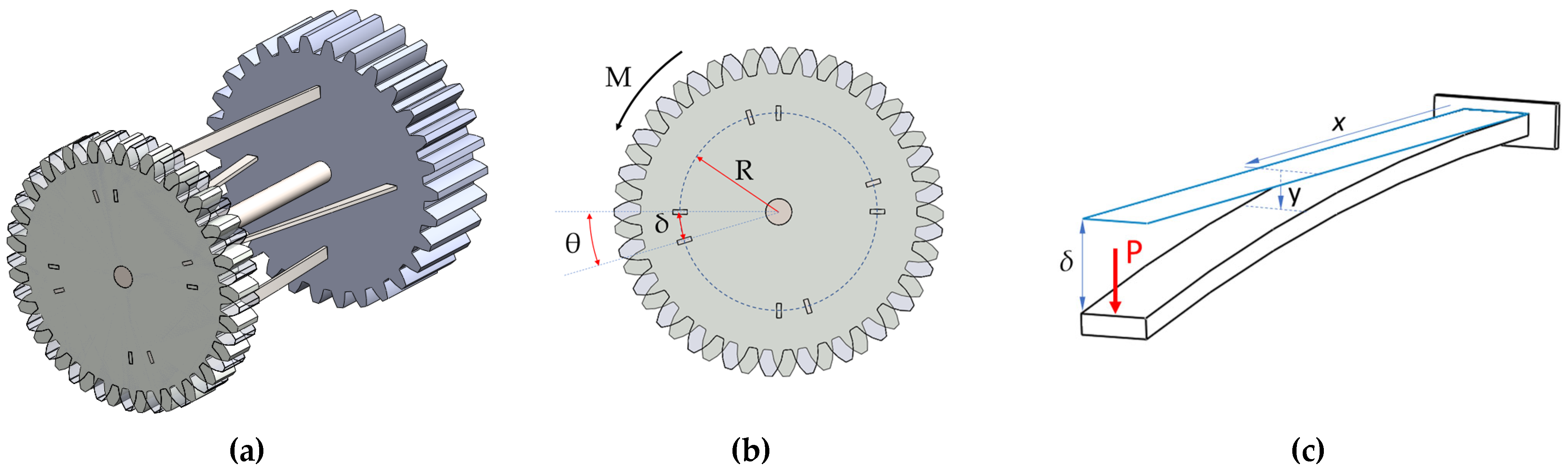
The elastic clutch mechanism consists of four small prismatic cantilever beams on the gear. The stiffness of the clutch is adjusted by changing the active clutch length of these elastic rectangular beams. This study is an advanced version of the previous work using cylindrical cross-section beams. Cylindrical beams subjected to dynamic bending have a higher risk of cracking in the cylindrical surface over time. For this reason, it is evaluated that prismatic beams will be more reliable than cylindrical beams in such a system. For this purpose, the clutch mechanism’s previous design was revised with the prismatic beams, as shown in
Figure 1. However, a rectangular beam will simultaneously be subject to bending and torsion, complicating the analytical solution. Although the combination of torsion and bending of rectangular beams is a fundamental problem, only a few studies were found examining this mechanical problem. Yong Lin et al. [
20] investigated the combined torsion and the bending problem arising in a beam with simple support under the effect of a force offset from the bending axis. Sinha [
21] investigated the cantilever Timoshenko beam’s combined torsion and bending problem subjected to the impact load from the free end.
The elastic clutch mechanism consists of elastic beams of rectangular cross-sections connecting the output and input gears. The previous version of the design with cylindrical beams and the current version with prismatic beams are shown together in
Figure 1a and 1b. The adjustable clutch mechanism can be inserted between the output shaft and the gear in the actuator design with adjustable stiffness, as shown in
Figure 1a, or it can be placed in an in-between position in the gear system. To highlight this, the design is shown in
Figure 1b between two gears. The beams must be at least two for a balanced moment transfer. Since the high number of beams will cause strength problems in gear, it is considered that four beams will be suitable for these dimensions. Rectangular elastic beams have both torsional and bending flexibility. Four elastic beams that transmit the moment from the input gear to the output gear are positioned. Joint stiffness can be adjusted by changing the active length of these elastic beams that transfer torque to the output gear. The most important feature of this design is that it controls the spring stiffness by directly changing its active length. This way, the spring characteristic is changed directly to control the actuator’s stiffness instead of changing the spring pre-tension or moment transfer ratio.
One of the simplest ways to change the stiffness of the elastic clutch is to control the active length of an elastic beam subject to bending. The system functions as a rigid actuator when the clutch length is minimum. However, when the active clutch length is maximum, the actuator works as an elastic actuator. The clutch mechanism introduced in this design transforms this property of the beam subjected to bending into an angular spring whose stiffness can be adjusted. Since the cylindrical cross-section beam version we introduced earlier appears to break easily under repeated loads subjected to bending, a rectangular prismatic beam design with high resistance to repetitive bending loads is developed in this new version.
2.1. Simple Analytical Calculation
The four rectangular steel beams used in the adjustable clutch design are forced torsion and bending, as shown in
Figure 1d. For this reason, the torsion and bending problems of non-cylindrical beams should be examined together to calculate stiffness values. In a rectangular beam under the effect of torsion, the corner angles remain 90 degrees after torque is applied. The absence of distortion in the corners indicates that the shear stress is zero at these points. The rules of the theory of elasticity are used to solve the torsion problem of rectangular shafts. The relationship between the torsion moment and the torsion angle can be derived from the theory of elasticity. As long as the beam remains elastic under the exerted moment, the linear relationship will be seen between the torsion moment and the torsion angle, as shown in Equation (1). The slope of the torsion moment-torsion angle curve will indicate the torsional stiffness as given by Equation (2) [
22].
Here,
ktorsion represents the total torsional stiffness of the elastic clutch;
Ttorsion, torsion moment;
G, shear modulus;
β, section ratio effect;
a,b, dimensions of beam section; and
L, active clutch length (
Figure 1d).
Depending on the active clutch length, the cantilever beams used in the stiffness adjustable clutch mechanism are forced to bend, as shown in
Figure 2b. The bending stiffness in cantilever beams is based on three essential properties: the moment of inertia of the beam cross-section, the elastic modulus of the material, and the beam’s active length. In a cantilever beam forced by force P, the clutch point’s deflection (active endpoint) is indicated by
δ. This deflection is equal to the product of the torsion angle and the radial distance of the beam from the gear center (
Figure 2a). Using these relations, the following expression is obtained between the moment and the rotation angle performed against bending resistance.
Here,
kbending represents the total bending stiffness of the adjustable clutch;
Tbending, bending moment; E, modulus of elasticity of the beam material;
I, the moment of inertia of the beam section (
I =
a3b/12); R, distance from the center of the gear to the center of the four beams (
Figure 2a); and L, active clutch length (
Figure 2b). An important point should be noted here. The moment of inertia in the bending equation will not remain constant and will change due to the beam’s twisting. For a more precise calculation, the variation of the moment of inertia with the torsion angle must be considered. However, this calculation is quite complex, and the experimental results of this study show that torsional stiffness is more dominant than bending in long thin beams. While the beam bending equation gives correct results for long beams, long beams’ bending stiffness is negligible compared to torsional stiffness. Therefore, a more straightforward solution is followed in this study. This change in the moment of inertia is neglected in analytical calculations.
In a simplified calculation, the sum of the torsional and bending stiffness can be considered as the stiffness of the joint as given below.
Here, kθ represents the total angular stiffness of the adjustable clutch, and θ represents the torsion angle. The results section will discuss this assumption’s correctness by comparing analytical, numerical, and experimental results.
2.2. Experimental Setup
The test structure consists of four elastic prismatic beams, support, and a moment arm, which can be placed in various radial locations. In order to simulate the elastic clutch in experiments, a fixture shown in
Figure 3a was designed in SolidWorks 2021 and printed by a 3D printer. The fixture was rigidly assembled on the test machine with two bolts and nuts. The span between the center of the rotation (clutch center) and the applied force point was set to 110 mm. All experiments were conducted using a tabletop machine (
Figure 3b) specially designed for very low-strength materials [
23]. The applied force from the 30 kg load cell (Zemic) and displacement from the rotary encoder (Omron) were recorded at a rate of 30 DPS. Head speed was constant for all tests and set to 10 mm/min. The representative force–displacement curve and corresponding Torque–rotation angle curve were demonstrated in
Figure 3c. The slope of the Torque/rotation curve was pointed as the experimental stiffness of the clutch.
2.3. Numerical Analysis:
Numerical analyses based on the finite element method (FEM) were performed by ANSYS R2020 Workbench software. There were three different radial positions and seven active clutch lengths, so 21 configurations were designed using SpaceClaim 2020 software. Unlike the experimental design, the FEM design was formed in compliance with the actual geometry of the elastic clutch mechanism that will be assembled into actuators. Boundary conditions in the analysis were determined as the input gear is fixed, the output gear is under the 0.5 Nm torque, contact between the input gear and the elastic beam is bonded, and the contact between the output gear and the elastic beam is frictionless (
Figure 4a). The gears’ materials used in the analyses were assumed to be structural steel which has a modulus of elasticity 200 GPa, and Poisson’s ratio is 0.30. The beam materials are assumed to be spring steel which has a modulus of elasticity 205 Gpa, and Poisson’s ratio is 0.30. After the mesh, the software produced 188635 quadratic elements and 339104 nodes, and all analyses were run by the same mesh generations. A cylindrical coordinate axis was placed at the center of the output gear, and the Y axis was set to the tangential axis. After the solution, directional deformation about the Y axis, equal to the arc length drawn by any displaced point on the output gear, was plotted. Therefore, the ratio of the directional deformation of the outer diameter about the Y axis to the outer radius of the output gear was determined as the rotation angle of the elastic clutch (
Figure 4b). To see whether or not the elastic beams remain elastic region under the 1Nm torque, which is two times higher than the applied torque in experiments, equivalent Von-Mises stress distribution is also plotted. A representative equivalent Von-Mises distribution graph is shown in
Figure 4c. Maximum stress was observed as 26 MPa at the configuration of R = 5 and L=35, which is under the yield point of the spring steel.
3. Results
The angular stiffness values of the joint can be obtained using Equations (2), (4), and (5), depending on the clutch length. As can be seen from Equation (2), torsional stiffness decreases linearly as the clutch length increases. Moreover, Equation (4) shows that as the clutch length increases, the bending stiffness decreases cubically. The computational results obtained with this simple analytical model are compared with numerical simulation and experimental results in this section. This way, it will be possible to analytically, numerically, and experimentally reveal how effectively the clutch mechanism performs the stiffness adjustment.
In analytical calculations, simulations, and experiments, the active clutch length of beams made of spring steel with a modulus of elasticity of 200 GPa and a shear modulus of 80 GPa varied from 0 to 35 mm. This value can be easily increased or decreased by lengthening or shortening the dimensions of the clutch mechanism. In all analyses, the variation of the elastic rotation angle of the joint against the moment was obtained for different active clutch lengths. Since the connection will be completely rigid when the active beam length is zero, and the stiffness will be theoretically infinite, it is not shown in the figures. It should also be noted here that the Euler–Bernoulli beam theory gives more accurate results in long thin beams. Therefore, analytical results are not expected to yield meaningful results for very short beams in bending.
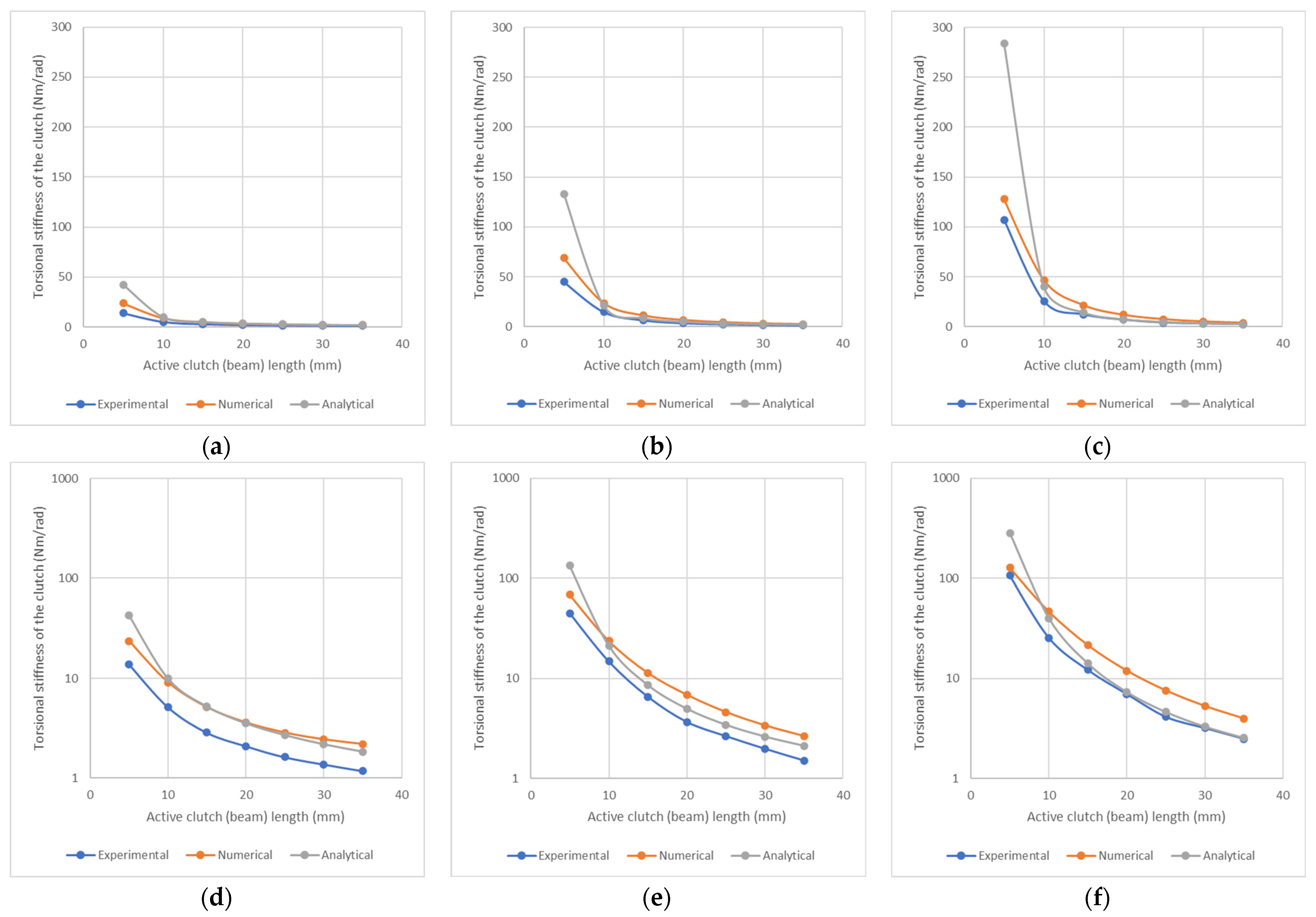
Figure 5 shows the analytical, numerical, and experimental variation of clutch stiffness concerning clutch lengths 5 to 35 mm in 5 mm increments. In
Figure 5a–c, elastic beams are placed in positions with radii of 5, 10, and 15 mm from the center, respectively.
Figure 5d–f logarithmic scale representation enhances the appearance as the stiffness varies widely. In these curves, grey lines show analytical results, orange lines show numerical (simulation) results, and blue lines show experimental results. While the active clutch length L = 35 mm, the clutch is in the most flexible coupling position. Both analytical, numerical, and experimental results show that the elastic joint’s stiffness increases as the beams’ radial position moves away from the center. Generally, there is compliance between analytical, numerical, and experimental results, which becomes more apparent as the active length of the beam increases. The simple beam theory in analytical calculations reveals a more accurate approach for long beams. In order to statistically evaluate the variation in analytical, experimental, and numerical stiffness values, the coefficient of variation values corresponding to different beam lengths (L) and different radial positions (R) are presented in
Figure 6. The maximum coefficient of variation is seen in configurations where the active beam length is 5 mm, while it remains around 30% in other configurations. The coefficient of variation (CoV) was calculated by using Equation (7) to evaluate statistically the dispersion of the torsional stiffness obtained from different techniques. In the formula,
ki indicates torsion stiffness and M is the arithmetic mean of the analytical, numerical, and experimental results at the same configurations. While the maximum coefficient of variation is seen in configurations where the active beam length is 5 mm, it remains stable at around 30% in other configurations.
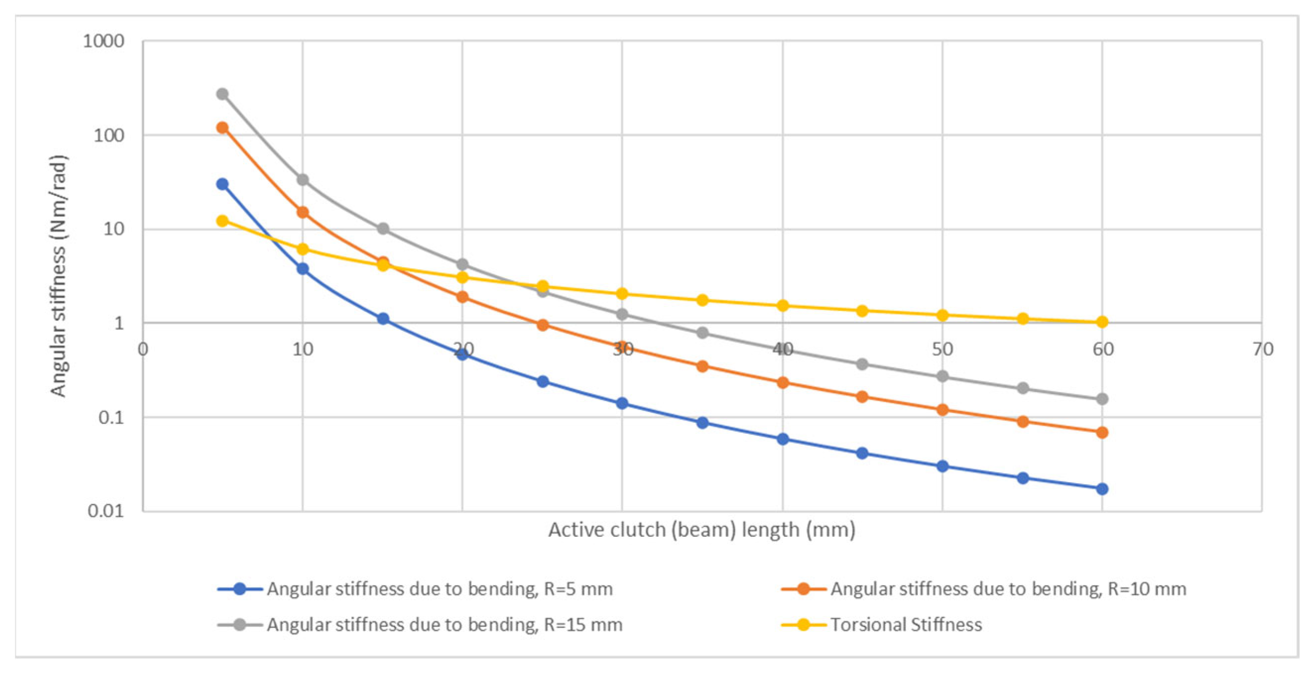
Figure 7 shows the joint stiffness (analytical results) due to the bending and the torsional stiffness of the four beams according to the clutch length on a logarithmic scale. The yellow line shows the angular stiffness of the joint due to the torsion of the beams. The blue line shows the angular stiffness of the joint due to bending for R = 5 mm, the red line shows the stiffness for R = 10 mm, and the grey lines show the stiffness for R = 15 mm. While the joint’s stiffness due to bending varies with the position of the beams (R), the analytically calculated total torsional stiffness of the beams is not affected by the radial location of the beams. If the R goes to zero, bending stiffness converges to zero, and the torsional stiffness gets more dominant in total stiffness. Moreover, increasing the active clutch length will decrease the bending stiffness, so the torsional stiffness became more dominant. However, it is impossible to reduce the R-value to less than 5 mm due to geometrical and manufacturing restrictions in experiments.
The torque value that will not cause plastic deformation in the elastic beams in the experimental setup was chosen as 0.5 Nm. The elastic rotation angle of the adjustable clutch for this torque value was determined analytically, numerically, and experimentally. For this value of the moment, the variation of the elastic clutch’s angular displacement with the clutch length is given in
Figure 8, both analytically, numerically, and experimentally. The highest elastic rotation value is seen in experimental results. Materials defects, gap tolerance, and measurement errors are not considered in numerical and analytical calculations. All these phenomena led to getting low stiffness (or high rotation) values in experimental measurements. Therefore, this difference between the experimental, numerical, and analytical results is acceptable.
4. Discussion
This study investigated a mechanically improved version of a novel stiffness adjustable elastic clutch design introduced earlier. In the clutch design developed using rectangular beams instead of cylindrical cross-section beams, the resulting torsional bending problem was solved using a straightforward approach. This simple analytical approach obtained the stiffness and angular deformation values for the adjustable stiffness clutch mechanism. Analytical results were compared with the numerical and experimental results with the measurements made on the developed simple experimental setup and simulation model. Moreover, the fact that the moment of inertia of the beam changes with torsion was not taken into account should make a difference between analytical and experimental results. Analytical, numerical, and experimental results were expected to differ in long beams with a significant torsion angle. However, no such effect is seen in the results because torsional stiffness becomes dominant in long beams compared to bending stiffness.
In the design, cross-section, section moment of inertia, and modulus of elasticity also affect the stiffness of the elastic clutch. Clutch length (beam length) is the easiest parameter to actively control among these parameters. For this reason, beam length was chosen as the control variable in the stiffness adjustment design, and beam length was emphasized in the analyses. If the design is modified, the radial position of the beams can also be actively controlled and used for stiffness adjustment. To guide future studies, the effect of the radial position of the beams is also shown for three different positions in the study. Different beam sections were not tested in the study, as the beam section is difficult to control actively.
The adjustable elastic clutch introduced in this study is suitable in size for use in a small standard servo actuator. The results show that the elastic coupling mechanism introduced in the article can adjust the stiffness in a wide range, and the design is simple enough to be produced in tiny and large sizes. Although the stiffness adjustment is made manually in the experimental test setup, stiffness adjustment can be made by adding a simple adjustment bolt or a servo motor. The stiffness cannot be actively controlled while the system is in motion, as an adjustment screw drives the clutch length. However, by connecting a second servo actuator, the stiffness can be actively controlled while the system is in motion. Since this study focused on the stiffness modeling of the clutch and the verification of analytical calculations by simulations and experiments, a simple manual adjustment was preferred. Future studies are planned to test the stiffness adjustment mechanism’s performance in legged locomotion mechanisms and robotic arms. This adjustable clutch design could be considered an alternative to existing designs due to its simple structure and wide range of stiffness control. In addition, it is planned to obtain a more precise analytical solution for a rectangular beam that is forced to bend and twist simultaneously, which is the basic element of the adjustable clutch mechanism.
5. Conclusions
The results show that the stiffness of the clutch mechanism can be adjusted over a wide range thanks to the prismatic beams’ bending and torsion-based design;
The simple analytical approach yields more accurate results as the torsion of the beam becomes dominant compared to its bending because the analytical approach neglects the change in the moment of inertia of the section in the bending problem;
It has been observed that as the active clutch length increases or the beams get closer to the center, the torsion of the beams is more dominant than the bending;
The stiffness in the adjustable elastic clutch mechanism is simple enough to be actively controlled by an additional servo motor while the system is in motion. This way, it has been evaluated as suitable for actuators with variable stiffness.
Author Contributions
Conceptualization, M.R. and K.T.; methodology, M.R. and K.T.; software, M.R. and K.T.; validation, M.R. and K.T.; formal analysis, M.R. and K.T.; investigation, M.R. and K.T.; resources, M.R. and K.T.; data curation, M.R. and K.T.; writing—original draft preparation, M.R. and K.T.; writing—review and editing, M.R. and K.T.; visualization, M.R. and K.T.; supervision, M.R. and K.T.; project administration, M.R. and K.T.; funding acquisition, M.R. and K.T. All authors have read and agreed to the published version of the manuscript.
Funding
This research was funded by Bursa Uludağ University with grant number FHIZ-2021-527.
Data Availability Statement
Not applicable.
Conflicts of Interest
The authors declare no conflict of interest.
References
- Geyer, H.; Blickhan, R.; Seyfarth, A. Spring-mass running: Simple approximate solution and application. J. Theor. Biol. 2005, 232, 315–328. [Google Scholar] [CrossRef] [PubMed]
- Cocuzza, S.; Doria, A.; Reis, M. Vibration-Based Locomotion of an Amphibious Robot. Appl. Sci. 2021, 11, 2212. [Google Scholar] [CrossRef]
- Hong, C.; Tang, D.; Quan, Q.; Cao, Z.; Deng, Z. A combined series-elastic actuator & parallel-elastic leg nolatch bio-inspired jumping robot. Mech. Mach. Theory 2020, 149, 103814. [Google Scholar]
- Nicholson, J.V.; Gart, S.; Pusey, J.; Clark, J.E. Evaluating the Efficacy of Parallel Elastic Actuators on High-Speed Variable Stiffness Running. In Proceedings of the 2020 IEEE/RSJ International Conference on Intelligent Robots and Systems (IROS), Las Vegas, NV, USA, 24 October 2020–24 January 2021; pp. 3641–3648. [Google Scholar]
- Takeuchi, M.; Katsura, S. Hopping Robot Using Variable Structured Elastic Actuators. In Proceedings of the IEEE/ASME International Conference on Advanced Intelligent Mechatronics (AIM), Boston, MA, USA, 6–9 July 2020; pp. 946–951. [Google Scholar]
- Vanderborght, B.; Albu-Schaeffer, A.; Bicchi, A.; Burdet, E.; Caldwell, D.; Carloni, R. Variable impedance actuators: A review. Robot. Auton. Syst. 2013, 61, 12, 1601–1614. [Google Scholar] [CrossRef]
- Van Ham, R.; Vanderborght, B.; Van Damme, M.; Verrelst, B.; Lefeber, D. MACCEPA, the mechanically adjustable compliance and controllable equilibrium position actuator: Design and implementation in a biped robot. Robot. Auton. Syst. 2007, 55, 10, 761–768. [Google Scholar] [CrossRef]
- Van Ham, R.; Thomas, S.; Vanderborght, B.; Hollander, K.; Lefeber, D. Compliant actuator designs: Review of actuators with passive adjustable compliance/controllable stiffness for robotic applications. IEEE Robot. Autom. Mag. 2009, 16, 81–94. [Google Scholar]
- Pratt, G.A.; Williamson, M. Series elastic actuators. In Proceedings of the IEEE International Workshop on Intelligent Robots and Systems, Pittsburgh, PA, USA, 5–9 August 1995; pp. 399–406. [Google Scholar]
- Migliore, S.A.; Brown, E.A.; De Weerth, S.P. Biologically inspired joint stiffness control. In Proceedings of the IEEE International Conference on Robotics and Automation, Barcelona, Spain, 18–22 April 2005; pp. 4519–4524. [Google Scholar]
- Tonietti, G.; Schiavi, R.; Bicchi, A. Design and control of a variable stiffness actuator for safe and fast physical human/robot interaction. In Proceedings of the IEEE International Conference Robotics and Automation, Barcelona, Spain, 18–22 April 2005; pp. 526–531. [Google Scholar]
- Hurst, J.V.; Chestnutt, J.; Rizzi, A. An Actuator with Mechanically Adjustable Series Compliance; Technical Report; Robotics Institute, Carnegie Mellon University: Pittsburgh, PA, USA, 2004; ISBN CMU-RI-TR- 04-24. [Google Scholar]
- Hollander, K.W.; Ilg, R.; Sugar, T.G.; Herring, D. An efficient robotic tendon for gait assistance. J. Biomech. Eng. 2006, 128, 788–791. [Google Scholar] [CrossRef]
- Jafari, A.; Tsagarakis, N.; Vanderborght, B.; Caldwell, D. A novel actuator with adjustable stiffness (AwAS). In Proceedings of the IEEE/RSJ International Conference on Intelligent Robots and Systems, Taipei, Taiwan, 18–22 October 2010; pp. 4201–4206. [Google Scholar]
- Jafari, A.; Tsagarakis, N.; Caldwell, D.G. AwAS-II: A new actuator with adjustable stiffness based on the novel principle of adaptable pivot point and variable lever ratio. In Proceedings of the IEEE International Conference on Robotics and Automation, Shanghai, China, 9–13 May 2011; pp. 4638–4643. [Google Scholar]
- Reis, M.; Ebrahimi, N.; Jafari, A. Elastic Actuator Design Based on Bending of Cylindrical Beam for Robotic Applications. Actuators 2020, 9, 80. [Google Scholar] [CrossRef]
- Lee, C.; Kwak, S.; Oh, S. Generalization of Series Elastic Actuator Configurations and Dynamic Behavior Comparison. Actuators 2017, 6, 26. [Google Scholar] [CrossRef]
- Quy, H.V.; Aryananda, L.; Sheikh, F.I.; Casanova, F.; Pfeifer, R. A novel mechanism for varying stiffness via changing transmission angle. In Proceedings of the IEEE International Conference on Robotics and Automation, Shanghai, China, 9–13 May 2011; pp. 5076–5081. [Google Scholar]
- Chaichaowarat, R.; Kinugawa, J.; Seino, A.; Kosuge, K. A Spring-Embedded Planetary-Geared Parallel Elastic Actuator. In Proceedings of the IEEE/ASME International Conference on Advanced Intelligent Mechatronics (AIM), Boston, MA, USA, 6–9 July 2020; pp. 952–959. [Google Scholar]
- Yong Lin, P.; Trahair, N.S. Inelastic Bending and Torsion of Steel I-Beams. J. Struct. Eng. 1994, 120, 3397–3417. [Google Scholar]
- Sinha, S.K. Combined Torsional-Bending-Axial Dynamics of a Twisted Rotating Cantilever Timoshenko Beam with Contact-Impact Loads at the Free End. J. Appl. Mech. 2007, 74, 505–522. [Google Scholar] [CrossRef]
- Francu, J.; Novackova, P.; Janicek, P. Torsion of a Non-Circular Bar. Eng. Mech. 2012, 19, 45–60. [Google Scholar]
- Reis, M.; Şerifağaoğlu, E. A Smart Handheld Welding Torch Device for Manual Spot Laser Welding. Appl. Sci. 2022, 12, 11137. [Google Scholar] [CrossRef]
| Disclaimer/Publisher’s Note: The statements, opinions and data contained in all publications are solely those of the individual author(s) and contributor(s) and not of MDPI and/or the editor(s). MDPI and/or the editor(s) disclaim responsibility for any injury to people or property resulting from any ideas, methods, instructions or products referred to in the content. |
© 2022 by the authors. Licensee MDPI, Basel, Switzerland. This article is an open access article distributed under the terms and conditions of the Creative Commons Attribution (CC BY) license (https://creativecommons.org/licenses/by/4.0/).


