Article

Numerical Simulation and Torsional Vibration Mitigation of Spatial Eccentric Structures with Multiple Magnetorheological Dampers

1
China-Pakistan Belt and Road Joint Laboratory on Smart Disaster Prevention of Major Infrastructures, Southeast University, Nanjing 210096, China
2
College of Mechanical and Electronic Engineering, Nanjing Forestry University, Nanjing 210037, China
*
Author to whom correspondence should be addressed.
Actuators 2022, 11(8), 235; https://doi.org/10.3390/act11080235
Submission received: 14 July 2022 / Revised: 5 August 2022 / Accepted: 15 August 2022 / Published: 16 August 2022
(This article belongs to the Special Issue Vibration Control and Structure Health Monitoring)

Abstract

:
Eccentric structures will have torsional vibrations subjected to earthquakes, which can accelerate the damage of structures, and even become the main cause of building collapse. Semi-active control systems equipped with multiple magnetorheological (MR) dampers have been widely applied in structural vibration control. In this study, numerical models of spatial eccentric structures with multiple MR dampers were established, and time history analysis was conducted to mitigate torsional vibrations of eccentric structures. Firstly, a full-scale spatial eccentric structure model with both plan asymmetry and vertical irregularity was established in OpenSEES, and the accuracy of the structure model was verified by comparisons with model results from SAP2000. Then, the mathematical model of MR dampers was introduced to the structure model using the ‘Truss’ element and self-defined material in OpenSEES, and damping forces obtained from the MR damper model were compared with experimental data. Finally, modal analysis and nonlinear time history analysis of the eccentric structure model equipped with multiple MR dampers subjected to different seismic excitations were performed. Comparisons between the seismic responses of the uncontrolled structure and the structure with multiple MR dampers were carried out to demonstrate the effectiveness of the MR control system. Numerical results show that the control system with multiple MR dampers can significantly attenuate the torsional vibrations of eccentric structures, and thus possess significant engineering application prospects.

1. Introduction

In order to meet the needs of functional diversity and urban planning of modern architecture, the structures often present asymmetric layout and irregular facade. The structures whose center of mass and rigidity are not coincident can be collectively referred to as eccentric structures [1]. Under the action of earthquake, the inertia force passes through the center of mass, while the restoring force of the lateral resisting members passes through the center of rigidity. Therefore, the eccentric structures not only vibrate horizontally, but also have torsional motion around the center of rigidity, forming the coupled translation-torsion vibration [2,3]. Meanwhile, the actual earthquake excitations contain multiple components, not only translational components in different directions, but also torsional components, which can lead to the torsional responses of structures. Theoretical research and earthquake damage investigations indicate that the torsional responses can concentrate the deformation in some columns and amplify the acceleration at certain floors, which will make the structure susceptible to further damage, especially for eccentric structures vulnerable to seismic excitations and wind loadings, and even become the main factor leading to the collapse of buildings in some cases [4,5]. Therefore, it is of great practical significance to mitigate the torsional vibration of eccentric structures under earthquake action.
Numerous studies have manifested that the traditional seismic design, such as improving the structural stiffness and ductility or using strong materials, cannot guarantee the safety of the structure under future dynamic loads, and cannot meet the economic requirements [6]. On this basis, the concept of structural vibration control was first proposed in the 1970s, which uses the control system attached to the structure to exert a group of control forces actively or passively in order to mitigate the structural response [7,8,9,10,11]. Among various vibration control methods, the semi-active control has shown obvious superiority in that it remarkably outperforms passive control and requires much less external energy than active control [12,13,14,15,16]. As a typical subset of semi-active control systems, MR dampers have the characteristics of high controllability, low energy consumption, fast response, mechanical simplicity, and reliable damping effect, and thus have been widely studied and applied in automobile suspension, cable and civil structures, and aerospace engineering [17,18,19,20,21].
In recent years, a wide range of analytical and experimental studies on structural torsional vibration control using MR dampers have been carried out. Yoshida et al. [22,23] proposed a MR control system to reduce the coupled translation-torsion motions in asymmetric buildings based on a clipped-optimal control algorithm, and this method was numerically assessed by two full scale irregular building models and experimentally verified by a two-story building with an asymmetric stiffness distribution. The results showed that the MR control system can significantly reduce the torsional coupled responses of irregular buildings. Li et al. [24] adopted a multi-state control strategy to mitigate the coupled translation and torsion responses of a three-story reinforced concrete frame–shear wall eccentric structure by three MR dampers, and the shaking table test results showed that MR dampers are effective for torsional seismic response control. Shook et al. [25] experimentally investigated the application of four MR dampers for the torsional response control of a 3-story, 9 m torsion-benchmark building using the fuzzy logic controller optimized by genetic algorithm. Bharti et al. [26] verified the effectiveness of MR damper-based control systems for torsional response mitigation through a numerical idealized one-story one-bay plan asymmetric building model and two MR dampers based on the Lyapunov stability theory. Hu et al. [27] adopted two pairs of eccentrically placed MR dampers to control the vibration of a 10-story irregular steel frame building by the clipped-optimal strategy using LQR algorithm. The numerical results demonstrated that the MR dampers can effectively reduce the inter-story drifts as well as roof displacements and accelerations of irregular structures. Zafarani et al. [28] proposed a coupled fuzzy logical control algorithm to simultaneously control two MR dampers, and its effectiveness was verified numerically by simulating nonlinear seismic response of a one-way asymmetric inelastic single-story structure model through time history analysis. Zafarani and Halabian [29,30] proposed an adaptive model-based strategy to mitigate the inelastic torsional responses of one-story and multi-story plan-asymmetric structures with MR dampers, where the changes of the system can be considered in determining the control force of MR dampers. Al-Fahdawi et al. [31] used multiple MR dampers to connect two full-scale coupled buildings for the vibration control of structural responses under bi-directional earthquakes, and the MR dampers were controlled by the adaptive neuro-fuzzy and simple adaptive control methods.
However, previous research efforts on the torsional vibration control using MR dampers have obvious limitations. In the numerical analysis of MR damped structures, simplified plane structure models with idealized linear beam-column elements have been established in most studies, which cannot capture the torsional vibration characteristics of spatial eccentric structures. It is difficult to simulate the nonlinear characteristics of MR dampers in time history analysis of MR damped structures using common finite element software. What is more, in most cases for structural vibration control using multiple MR dampers, the implemented MR dampers in the control system have obvious disadvantages. The control strategies for control systems with multiple MR dampers proposed by existing research are all ‘single-input and single-output’ control modes, that is, a separate controller is set for each MR damper, without the cooperation and interaction between different dampers [24,25,27]. Such decentralized control strategies require a large number of controllers, which greatly increases the cost of the control system, and easily leads to control imbalance and poor stability. Additionally, for the structures with both torsional and translational vibration, the suitable positions of MR dampers for these two types of vibrations are different, but the existing research does not distinguish the two types of dampers well [26,27,28,29]. Therefore, for control systems with multiples dampers, it is of practical significance to study the control strategy and device placement for control systems with multiple MR dampers.
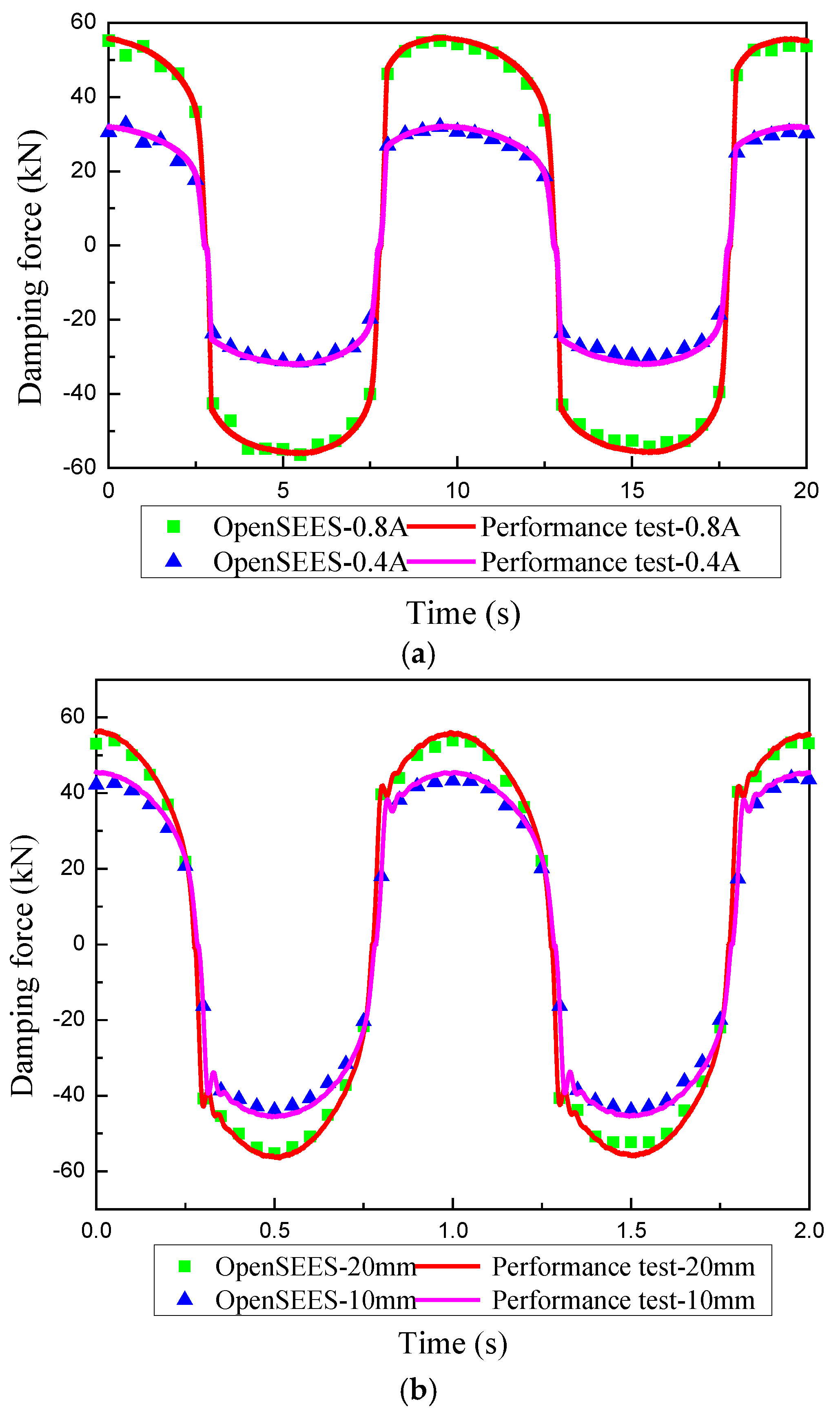
In this study, numerical simulation of spatial eccentric structures with multiple MR dampers were established, and modal analysis and time history analysis were conducted to reveal the effectiveness of MR control system in mitigating torsional vibrations of eccentric structures. Firstly, a self-programed full-scale spatial structure model with both plan asymmetry and vertical irregularity was established in OpenSEES to exhibit the torsional vibrations. Then, the mathematical model of MR dampers was introduced to the structure model based on the new material development function of OpenSEES, and the damping forces obtained from the MR damper model were compared with performance tests data. Finally, to evaluate the effectiveness of the MR control system with multiple MR dampers, modal analysis and nonlinear time history analysis of the numerical MR damped structure subjected to seismic excitations were carried out, and these numerical results were compared with seismic performances of the uncontrolled structure.

2. Numerical Modeling of Spatial Eccentric Structures

Full-scale spatial structures have numerous degrees of freedom, and the inelastic coupled translation-torsion vibrations under strong earthquakes are complex, which places high demands on the non-linear analysis and solution capabilities of finite element software. Meanwhile, in order to accurately evaluate the control effect of MR damping systems, it is necessary to introduce the mechanical model of MR dampers and the real-time control strategy to the time–history analysis of structures. Therefore, the finite element software is required to have flexible programmability and secondary development capabilities.
In this study, the OpenSEES (the Open System for Earthquake Engineering Simulation, version 3.3.0, the Pacific Earthquake Engineering Research Center, CA, USA) software developed by Berkeley was implemented for structural analysis. OpenSEES is an object-oriented, open-source software framework which can calculate the response of structures under earthquake excitations [32]. The most prominent advantage of OpenSEES is its open-source feature, which can develop and share new materials, new elements, or new algorithms through C++ language, providing a software platform for the introduction of nonlinear mechanical properties of MR dampers and real-time control algorithms to the numerical time–history analysis of MR damped structures.

2.1. Spatial Structure Modeling

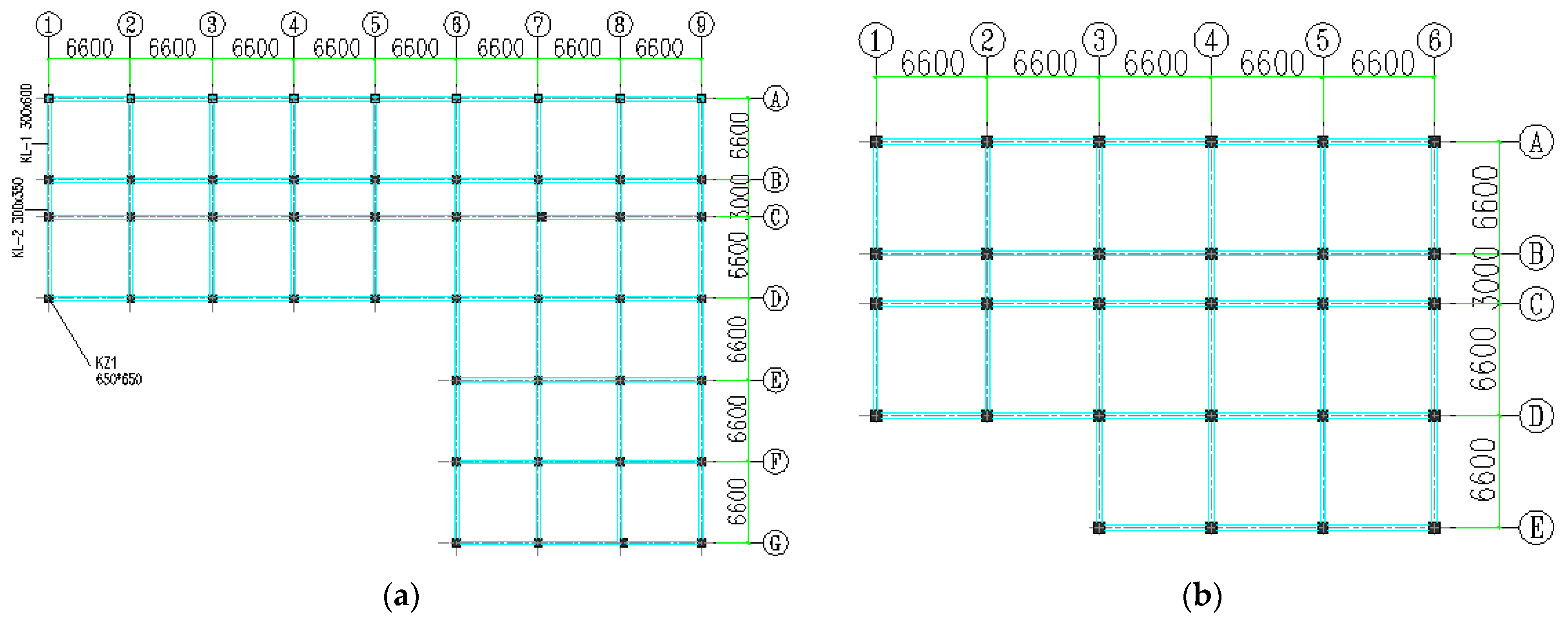
For spatial structures with irregular plane and elevation, its vibration form is complex, and the simplified models are difficult to describe the coupled translational and torsional vibration characteristics. It is necessary to establish a full-scale three-dimensional spatial model. Herein, a typical full-scale spatial eccentric structure was selected as the numerical example to stimulate the coupled translation-torsion vibration responses under earthquake actions. In practical engineering, the eccentricity of real building structures is often caused by the irregularity in both horizontal and vertical directions. Therefore, a full-scale ten-story reinforced concrete (RC) frame building with both plan asymmetry and vertical irregularity was modeled for this numerical study. The height of the first floor is 4.5 m and the upper floors are all 3.3 m high. The structure has three bays, where the span of the middle bay is 3 m and the side bay is 6.6 m. The cross section of the columns is 650 mm by 650 mm, the dimension of the beams at the side bay is 300 mm by 600 mm, and the dimension of the beams at the middle bay is 300 mm by 350 mm.
The structure model has both plan asymmetry due to the ‘L-shaped’ floor plan and vertical irregularity due to setbacks above the sixth floor, whose typical floor plans can be seen in 
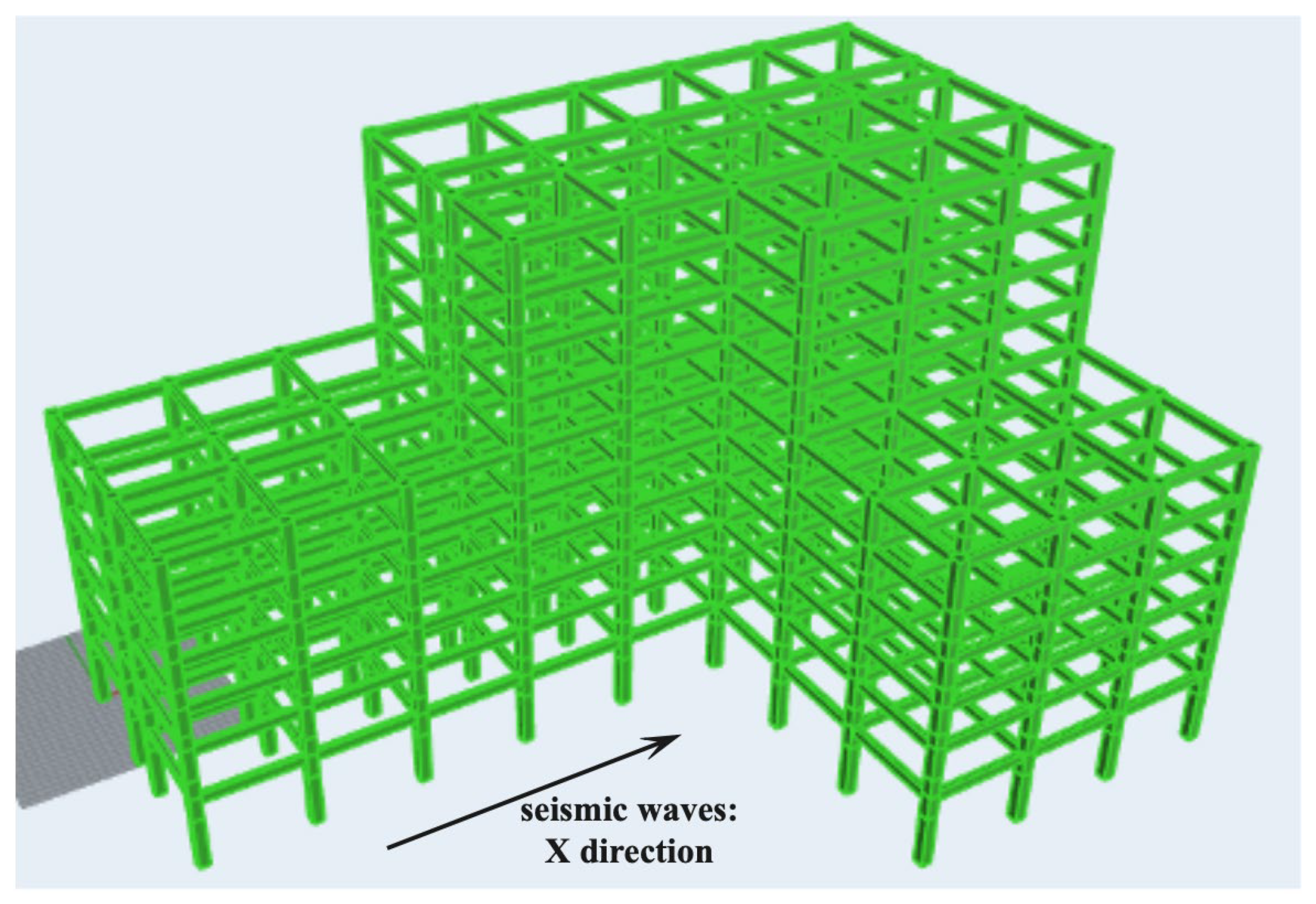
Figure 1. In order to truly reflect the spatial torsional vibrations of eccentric structures, the numerical structure in this study was modeled as a three-dimensional beam-column element system [33,34], considering the elastic–plastic deformation of beam and column members under strong earthquakes, as can be seen in Figure 2. The lateral load resistance system of the ‘L-shaped’ structure is strong in one direction but weak in the other, and due to the eccentricity of stiffness in the lateral load resistance system, the building is prone to torsional vibrations on the vertical axis.
In the numerical modeling through OpenSEES, the fiber model is used to simulate the member sections, in which the beam, column, and other member sections in the structure are discretized into several small elements, and each small element adopts the uniaxial constitutive relation of the corresponding material. The skeleton curve of the concrete constitutive model adopts the Kent–Scott–Park model, and the stress–strain relationship of the steel bar is described by the Menegotto–Pinto model [35,36]. In OpenSEES, the ‘concrete 02′ and ‘steel 02′ command are used to construct the concrete and steel material respectively. All the degrees of freedom of the bottom nodes of the structure are fixed, simulating the fixed connection between the real structure and the ground. In order to fully simulate the multi-directional translational and torsional vibration of the structure, the translational and torsional degrees of freedom (UX, UY, UZ, RX, RY, RZ) of the remaining nodes in the three directions are free.

2.2. Structure Model Verification

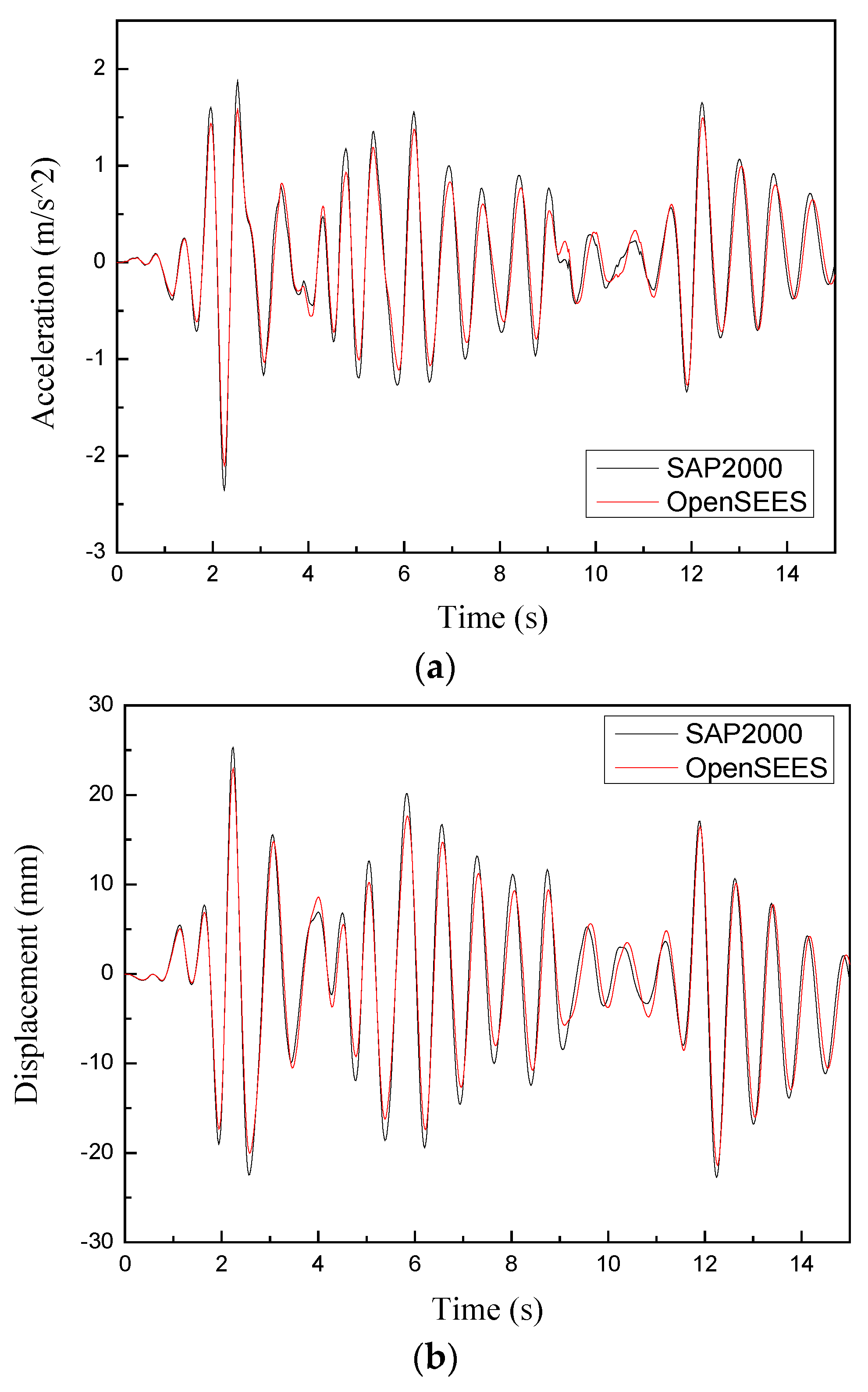
In order to verify the validity and accuracy of the self-programmed structure model in OpenSEES, comparisons of modal analysis results and dynamic time history responses calculated from OpenSEES (version 3.3.0) and SAP2000 (version 23.0) were carried out. The structure model set up in SAP2000 with node numbers can be seen in Figure 3. The El-Centro N-S component ground motions were used in the time history analysis, and the amplitude is scaled to 70 cm/s2. Seismic waves were applied unidirectionally in the X direction of the structure. The damping ratio of all modes was set to 5%.
The comparisons of modal analysis results are provided in Table 1, and comparisons of the acceleration and displacement time history responses of the top node (node 435) are plotted in Figure 4. The vibration type of each mode of the structure can be determined according to the participation mass ratio. When the participation mass ratio in the RZ direction of the structure is much larger than the sum of the participation mass ratios in the UX and UY directions, it means that the structure exhibits obvious torsional vibration; conversely, it means that the structure vibrates in the X-direction or Y-direction. As can be seen in Table 1 and Figure 4, the differences of the modal analysis results obtained from OpenSEES and SAP2000 are limited to 15%, and the acceleration time history responses of the top node in OpenSEES and SAP2000 are close, which indicates that the structure model established in OpenSEES is effective and accurate.
What is more, it can be revealed from Table 1 that the vibration types of the third and higher structure modes are torsional vibration or coupled translation-torsional vibration, and the ratio of the first torsional period to the first translational period of the structure is 0.86, close to the upper limit value 0.9 in the Chinese seismic design code [37], which further proves that the established numerical model is a typical spatial eccentric structure with weak torsional resistance. Therefore, it is necessary to suppress the torsional irregularity of the eccentric structure using vibration control devices.

3. MR Damper Modeling

3.1. Performance Tests of MR Dampers

The vibration control devices implemented to the established structure model for vibration mitigation are MR dampers. Utilizing the reversible fluid–solid conversion characteristics of MR fluid under the action of a magnetic field, the output of MR dampers can be adjusted in real time according to the external excitations and the vibration response of structures, by changing the excitation current. Due to the intrinsically nonlinear characteristics of MR dampers, accurate and efficient mathematical models to properly describe their behavior are crucial for the design of semi-active control systems and the responses predication of MR damped structures.
In order to provide experimental data basis for parameter identification of MR dampers, performance tests of a single-coil MR damper were carried out [38], as can be seen in Figure 5. The MR fluid used in this MR damper was the highly stabilized MR fluids based on MWCNTs/GO composites coated ferromagnetic particles prepared in our previous studies [39], and the basic properties of the MR fluid are listed in Table 2.
The magnetic characteristics of MR dampers have significant influence on the mechanical properties, so it is necessary to study the magnetic field distribution of this MR damper. The single-coil MR damper is axisymmetric, so it can be simplified as a two-dimensional model with ANSYS, with the axial direction of the damper as the symmetric axis. Figure 6 shows the magnetic induction lines and the magnetic induction intensity distributing of the single-coil MR damper. As can be seen from this figure, the magnetic induction lines all go perpendicularly through the damping gap, and the magnetic induction intensities in the damping gap is uniformly distributed, with nearly 200 mT, when the excitation current is 2.0 A.
The force–displacement and force–velocity curves of the MR damper were plot‘ted in Figure 7a,b, respectively. In Figure 7, the excitation frequency was 0.1 Hz, and the displacement amplitude was 5 mm. As can be seen from this figure, the force–displacement and force–velocity curves of MR dampers exhibit significant nonlinear hysteresis characteristics. In Figure 7a, when the excitation current gradually increases from 0 A to 1.5 A, the damping force increases greatly, but when the excitation current increases from 1.5 A to 2.0 A, the damping force does not change much, with only a small increment. It can be inferred that the saturation current of this MR damper is 1.5 A. Additionally, when the excitation current increases from 0 A to 1.5 A, the damping force increases from 2 kN to 8 kN, which shows that the damper has good adjustable performance. It can be seen from Figure 7b that the damping force of the MR damper first increases rapidly and then tends to be flat with the increase of velocity. In the high-velocity region, the damping force of the MR damper is basically unchanged, because this period is the process of the damper piston moving rapidly from one end to the other end, and the damping force is stable around the peak value during this process. When the piston moves to one end and is ready to turn, the damping force will drop rapidly.
Based on the performance tests results and the phenomenological models for MR dampers [40], a microstructure-based sigmoid model for describing the mechanical properties of MR dampers affected by MR fluid microstructure, magnetic saturation, excitation properties, and current was proposed in our earlier publications [41]. This model does not need to solve the differential equations, with only three undetermined parameters, and thus is suitable for applications in the practical vibration control of MR damped structures. In this study, the damping force of MR dampers f d was calculated using this model, as can be seen in Equation (1):
f d = 2.07 + 12 Q η 12 Q η + 0.4 w h 2 τ y τ y L t · A p h 1 e k x ˙ + x h ˙ 1 + e k x ˙ + x h ˙ + C b x ˙
in which k , x h ˙ , and C b are the parameters of the sigmoid model related to the current, excitation frequency, and displacement amplitude, and can be identified based on the performance test results; x ˙ is the velocity of the piston rod; Q is the volumetric flow rate; η is the viscosity of MR fluid with no magnetic field; w is the mean circumference of the damper’s annular damping gap; h is the gap between the outer cylinder and the piston; τ y is the yield shear stress of MR fluid; A p is the cross-sectional area of the piston head, A p = D 2 d 2 / 4 ; D is the piston diameter; d is the piston rod diameter; L t is the working length of the damping gap.
The parameters to be identified in this model include the curve slope k , the crossing velocity x h , ˙ and the damping coefficient C b . The curve slope k is the slope of the hysteresis curve when the velocity is equal to zero, the cross velocity x h ˙ is obtained by the intercept of the force–velocity curves on the abscissa axis, and the damping coefficient C b is the slope of the high velocity region of the hysteresis curve, as can be seen in Figure 8. All three parameters are related to the excitation current and maximum velocity x ˙ m a x . In this study, parametric identification was performed in Origin software, and ‘nonlinear surface fitting’ was used to fit the relationship between the three parameters with excitation current and maximum velocity. The function used in the parametric identification is Poly2D.
Considering the size of the spatial structure model, the dimensions of the MR damper were selected so that the MR damper can obtain the maximum output of 10 kN and the adjustable coefficient over 3, as listed in Table 3.

3.2. MR Damper Modeling and Verification

The proposed mathematical model in Equation (1) essentially defines the force–velocity relationship of MR dampers, so this relationship can be simulated in OpenSEES as a new material. The force generated by MR dampers on the structure is only in the axial direction, and the ‘Truss’ element in OpenSEES is an element that transmits only axial force, thus the ‘Truss’ element and the self-defined new material can be combined to establish a mathematical model for describing the nonlinear mechanical properties of MR dampers.
The uniaxial material in OpenSEES that describes the stress–strain relationship is adopted to define the new material. In order to convert it into the force–velocity relationship of MR dampers, the ‘setTrailStrain’ function is used to obtain strain and strain rate (the velocity value x ˙ in Equation (1)). Then, the material property of the ‘Truss’ element is defined as the self-defined new material, and the cross-section area of the element is defined as 1. Finally, the damping force of the MR damper can be obtained from the axial force of the element.
By consolidating the element at one point and applying a sinusoidal displacement load to another point, the damping force of the MR damper model at different time can be obtained. In Figure 9a, the sinusoidal displacement loads applied to the element have the excitation frequency of 0.1 Hz, the displacement amplitude of 20 mm, and the current of 0.4 A and 0.8 A, and in Figure 9b, the sinusoidal displacement loads applied to the element have the excitation frequency of 1.0 Hz, the current of 0.4 A, and the displacement amplitude of 10 mm and 20 mm, which are both the same as the loading conditions of the MR damper performance tests, and the parameters of the model in OpenSEES are the same as the dimensions of the MR damper [38], so the accuracy of the MR damper model established in OpenSEES can be verified by comparing the damping forces calculated from OpenSEES with performance test results.
Figure 9 compares the damping forces calculated using the developed model in OpenSEES and the performance test results [38], in which the basic dimensions of the MR damper and properties of MR fluid are the same as the model parameters in Table 2 and Table 3. As can be seen from these figures, the damping forces of the MR damper calculated by the OpenSEES model are basically consistent with the performance test results, and can reflect the real-time variation trend of the damping force with time. Therefore, it can be concluded that using the ‘Truss’ element and the self-defined new material in OpenSEES, the developed model can finely describe the nonlinear dynamic properties of MR dampers. Introducing the MR damper model into the established structure model, the numerical MR damped structure model is established, and the dynamic responses of the MR damped structure under earthquake actions can be obtained.

4. Control System with Multiple MR Dampers

The essence of structural vibration control is to minimize the structural vibration response by establishing the appropriate feedback relationship between the control force and the measured structural vibration response as well as external excitation. Therefore, structural vibration control is essentially an optimization process of control parameters.
For eccentric structures with coupled translation-torsion responses, a control system equipped with multiple MR dampers is necessary, which makes the structural vibration control a more complex problem. On the one hand, for effective coupled torsion-translation vibration mitigation, the feedbacks to the control system need the combination of several parameters, including structural vibration response signals (displacement, acceleration, torsion angle) and earthquake excitation signals. On the other hand, in order to realize real-time cooperative control of multiple MR dampers, the control system is required to output different excitation currents to multiple dampers at the same time. Therefore, the control system involving multiple MR dampers is essentially a multi-input, multi-output (MIMO) system.
When multiple MR dampers are arranged in real-life high-rise buildings, it is impractical to equip each damper with a controller, and not every story of the structure has room for control and sensing systems. What is more, if too many controllers are involved in the control system, the stability and robustness of the system are not guaranteed. Fewer controller and sensors may be more applicable, stable, and economical for practical application.
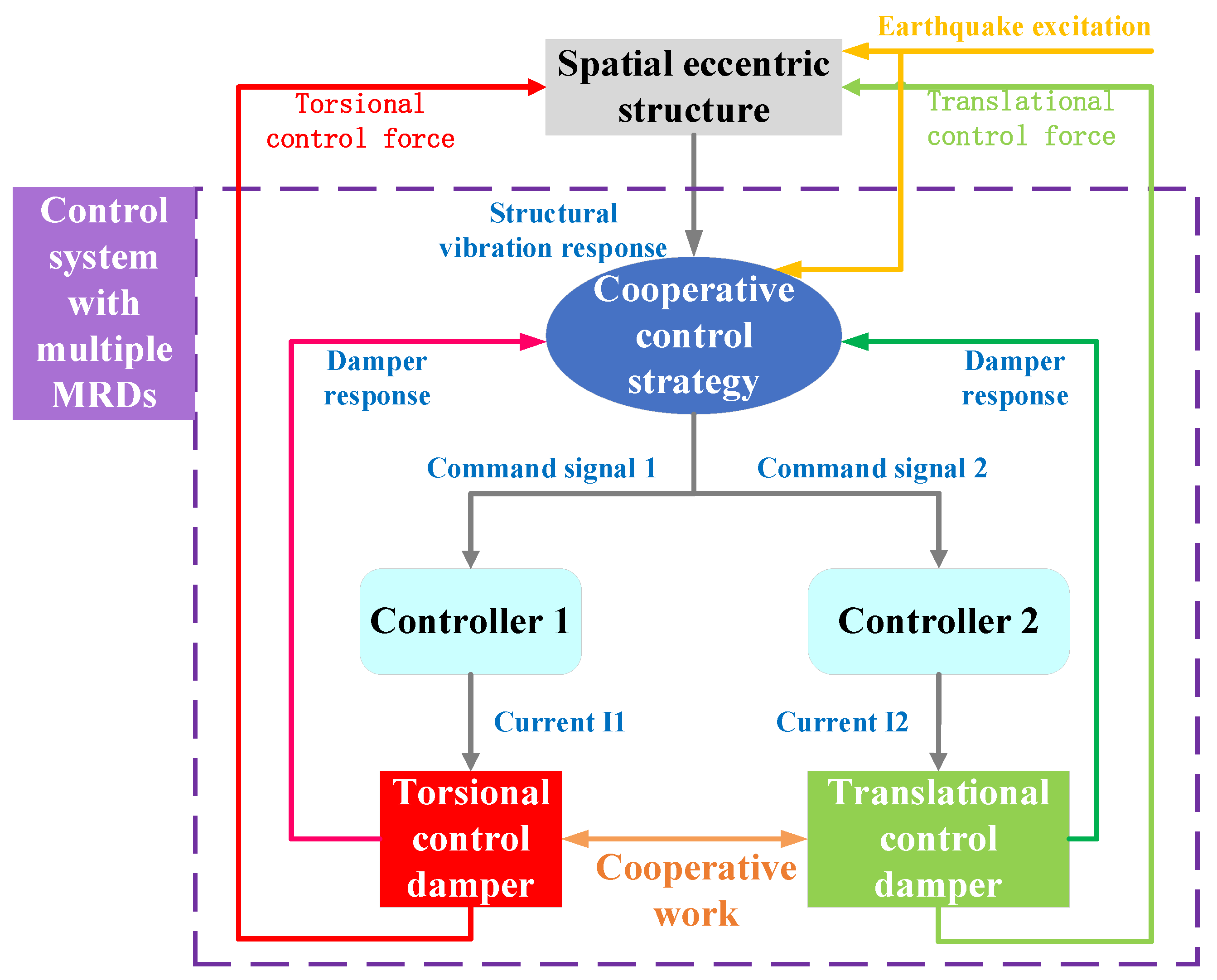
In this study, only two controllers are implemented to the control system with multiple MR dampers, where one controller outputs current to the dampers responsible for translational vibration control (‘translational control damper’), while the other controller outputs current to the dampers for torsional vibration control (‘torsional control damper’). The two controllers simultaneously output different currents to the two types of MR dampers, considering the cooperative work between the translational control dampers and the torsional control dampers, so as to achieve the optimal control on the coupled translation-torsion vibration of spatial eccentric structures, which is the basic concept of the control strategy proposed in this study.

4.1. Performance Criteria of Eccentric Structures

Firstly, in order to optimize the damping effect of the MR control system, a parameter representing the overall structural response requires to be minimized. For eccentric structures with coupled translation-torsion vibration, inter-story drift ratio and inter-story torsion angle were assigned as the performance criteria, in which the inter-story drift ratio characterizes the translational vibration, and the inter-story torsion angle reflects the torsional vibration.

4.2. Feedbacks to MR Control System

Then, the control system needs appropriate feedback to adjust the excitation current to MR dampers. As the output of MR dampers is directly related to the corresponding velocity, the velocity at the installation position of the MR damper was chosen as the feedback to the control system. In addition, in order to avoid the overcontrol of the structure by the MR control system under small earthquakes, the amplitude of the earthquake excitations was also considered.

4.3. Control Strategy

In general, the equation of motion for a spatial eccentric building equipped with multiple MR dampers subjected to earthquake excitation can be written as:
M s x ¨ + C s x ˙ + K s x = M s I x g ¨ + D U  
in which M s , C s , and K s are the mass, damping, and stiffness matrices of the eccentric structure, respectively; x , x ˙ , and x ¨ are the displacement, velocity, and acceleration vector of the eccentric structure; x g ¨ is the acceleration vector of the earthquake excitation; D is the location matrix of MR dampers; U is the control force vector of MR dampers; I is the identity matrix.
Equation (2) can be reduced to first-order and written in the state-space form as:
Z ˙ = A Z + B U + E x g ¨
Z = x x ˙ T  
A = 0 I M s 1 K s M s 1 C s ,   B = 0 M s 1 D ,   E = 0 I  
in which Z is the state vector; A is the system matrix; B is the distribution matrix of the MR damping force; E is the distribution matrix of the earthquake excitation.
Figure 10 is the work flow diagram of the control system with multiple MR dampers, and the detailed steps to implement the control strategy for the control system with multiple MR dampers can be seen from this figure. The spatially eccentric structure will have coupled translation-torsion vibrations under earthquake excitations. The proposed control strategy will output corresponding command signals to the two controllers in the system according to the structural vibration response and seismic excitation collected by the sensors. The two controllers output different currents to the two types of MR dampers arranged in the structure to ensure the cooperative work between them. Additionally, the vibration signal of MR dampers will also be output to the control strategy, and the control system output by the control strategy can be adjusted in real time. Ultimately, two types of MR dampers apply torsional and translational control forces to the structure, forming a complete closed-loop control of the coupled translation-torsion vibrations of the spatial eccentric structures.
In Figure 10, there are two problems to be solved for the practical application of the control system with multiple MR dampers. One is how to determine the excitation currents of the two controllers, and the other is how to allocate the two excitation currents to ensure the cooperative work of the two types of MR dampers. Firstly, the excitation current I 1 is input to the torsional control damper, thus the current value is determined by the real-time response of the torsional control dampers. Similarly, the current value of the excitation current I 2 is determined by the real-time response of the translational control damper. Equations (6) and (7) are the criterion for current determination of the torsional control and translational MR dampers, respectively. Since there are multiple MR dampers, the current values I 1 and I 2 obtained from Equations (6) and (7) are within a range. In Equations (6) and (7), I m a x is the saturation current of the MR dampers, n is the total number of the torsional control dampers, m is the total number of the translational control dampers, I 1 i is the excitation current for the i th torsional control damper, v i is the velocity of the i th torsional control damper, I 2 t is the excitation current for the t th translational control damper, v t is the velocity of the t th translational control damper, μ is the coefficient describing the relationship between the velocity and the output of MR dampers, which needs to be determined according to the performance test results. In this paper, μ is set as 3 × 10 6   N · s / m .
I 1 i = I m a x   μ · v i I m a x μ · v i   μ · v i < I m a x   i = 1 ~ n
I 2 t = I m a x   μ · v t I m a x μ · v t   μ · v t < I m a x   t = 1 ~ m  
Secondly, it is necessary to select two excitation current values from the two current ranges obtain from Equations (6) and (7) to complete the cooperative work of the two types of MR dampers. In order to achieve a good control effect on both the translational and torsional vibrations at the same time, inter-story drift ratio and inter-story torsion angle are selected as the evaluation indicators. The objective function J z is shown in Equation (8), where γ t and γ t 0 are the inter-story drift ratio of the top floor of the MR damped structure and the uncontrolled structure, respectively; θ t and θ t 0 are the inter-story torsion angle of the top floor of the MR damped structure and the uncontrolled structure, respectively; α and β are the weighting coefficients of inter-story drift ratio and inter-story torsion angle, respectively, which are both taken as 0.5 in this paper.
J z = α γ t γ t 0 + β θ t θ t 0
Finally, the genetic algorithm is adopted to optimize the two excitation current values, and the goal is to minimize the objective function, and Equations (6) and (7) are the constraint conditions. Within the range of current I 1 and I 2 , multiple sets of combined values are selected as the initial population, and new populations are obtained through continuous crossover and mutation, the fitness of each generation is calculated, and the optimal set of current I 1 and I 2 is finally obtained. In the optimization process, the optimal excitation currents for controller 1 and controller 2 can be obtained, and the cooperative control of the torsional control dampers and translational control dampers is achieved.

4.4. Placement of Multiple MR Dampers

For the semi-active control system with multiple MR dampers, another important issue is the placement of control devices, which has significant influence on its damping effect. In this study, the placement configuration of MR dampers is determined based on the inter-story drift ratios of the structure. Vertically, the floors where the inter-story drift ratios are significantly larger than other floors are the weak floors of the structure, and dampers should be arranged on these floors. In each floor, MR dampers for torsional vibration mitigation need to be placed at the corners or edges, as far away as possible from the center of mass, while the dampers for translation vibration mitigation are placed near the center of mass.
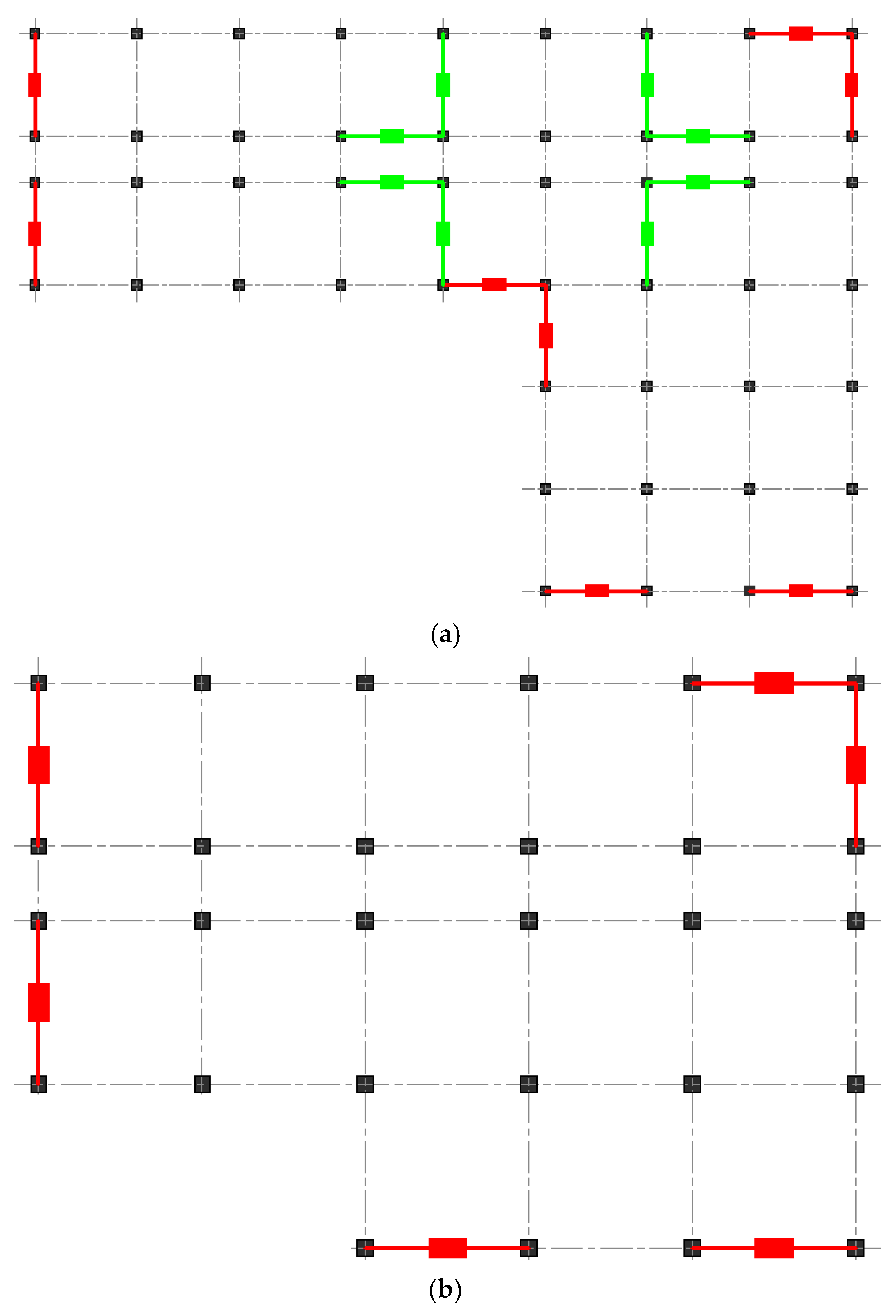
For the 10-story frame structure model established in this study, the lateral structural deformation is mainly concentrated in the lower floors, so both translational control dampers and torsional control dampers are placed in 1th–6th floors, and the 7th–10th floors only have torsional control dampers. The detailed placement of MR dampers in different floors can be seen in Figure 11. In this figure, the green devices are the translational control dampers, and the red devices are torsional control dampers. As can be seen from Figure 11, a total number of 120 MR dampers are implemented in this structure for vibration control.

5. Results and Discussions

The multiple MR dampers in Figure 11 with related controllers, sensors and power sources form a complete semi-active control system, and the proposed control strategy is responsible for calculating corresponding currents for different dampers in the control system to mitigate the coupled translation-torsion vibration of the structure. In order to evaluate the performance of the control system with multiple MR dampers, the simulation results and comparisons with seismic responses of the uncontrolled structure are discussed.

5.1. Modal Analysis

Modal analysis can provide the parameters that reflect the performance of a structure, and can be used to qualitatively access the basic dynamic properties. Therefore, the modal analysis of the MR damped structure is carried out firstly. Table 4 shows the modal analysis results of the MR damped structure. Compared with the model analysis results of the uncontrolled structure in Table 1, the dynamic properties of the eccentric structure are significantly changed due to the application of MR dampers. The uncontrolled eccentric structure exhibits obvious coupled translation-torsion vibration characteristics, while the vibration responses of the MR damped structure are mostly translational (the first three vibration modes are translation vibrations, and there is no coupled translation-torsion vibration), indicating that the control system with multiple MR dampers can remarkably mitigate the torsional vibration of spatial eccentric structures. The ratio of the first torsional period to the first translational period of the structure decreases from 0.86 to 0.53, which proves that the torsional stiffness of the structure has been significantly improved with the control system of multiple MR dampers.

5.2. Time History Analysis

To quantitatively evaluate the effectiveness of the proposed control strategy for multiple MR dampers, nonlinear dynamic time history responses of the numerical structure due to earthquakes were simulated. The earthquake excitations used in the time history analysis are the unidirectional El Centro and Taft ground motions, and the amplitude is scaled to 400 cm/s2. Both ground motions were applied in the The duration of the earthquake excitations is set to 15 s, with the step of 0.02 s. The significant parameters selected to assess the control performance of the MR control system in torsional and translational vibration mitigation are node acceleration, node displacement and inter-story torsion angel. The node displacement response of is displacement relative to the ground, while the node acceleration response of is the absolute acceleration.
The node acceleration and displacement responses are obtained from the time history results of the node at the top floor (node 435 in Figure 3). Figure 12 shows the top node acceleration time history responses of the uncontrolled and the structure with multiple MR dampers controlled by the cooperative control strategy. The corresponding displacement responses are plotted in Figure 13. As can be seen from these two figures, with the implementation of the control system with multiple MR dampers, the node acceleration and displacement responses are significantly attenuated. In addition, under different seismic waves, the damping effect of the control system with multiple MR dampers on the structural displacement is obviously better than that of the acceleration. This is because the setting of MR dampers will increase the stiffness of the structure, thereby amplifying the acceleration response of the structure to a certain extent, and ultimately leading to a limited control effect of the acceleration responses.
In order to verify the suppression effect of the multiple MR dampers in the torsional irregularity of spatial eccentric structures, the inter-story torsion angles of the uncontrolled and MR damped structures are compared. The inter-story torsion angle can be obtained by subtracting the time–history curves of the rotation angles of the upper and lower floors around the rigid center and then taking the maximum absolute value, and it can intuitively reflect the torsion degree of each story for torsional irregular structures, as can be seen in Figure 14.
The inter-story torsion angles of the uncontrolled and MR damped structure are plotted in Figure 15. After the implementation of the control system with multiple MR dampers controlled by the cooperative control strategy, the inter-story torsion angles of all floors are reduced to 2%, within the code limit, showing that the torsional vibrations of the spatial eccentric structure are obviously mitigated.
What is more, it can be seen from the inter-story torsion angles of the uncontrolled structure that due to the sudden change in vertical stiffness in the 7–10 floors of the structure, the top of the structure exhibits amplification of the torsional vibration response. After the implementation of MR dampers that control the torsional vibration, the torsional vibrations at the top floors are effectively mitigated.
In summary, it can be revealed from these simulation results and comparisons that the semi-active control systems with multiple MR dampers are effective in mitigating both the translational and torsional vibrations of spatial eccentric structures.

6. Conclusions

In this study, numerical models of spatial eccentric structures with multiple MR dampers were established in OpenSEES, and numerical analysis was conducted to reveal the effectiveness of the control system with multiple MR dampers. The following are the main conclusions drawn from this study:
(1) The self-programmed structure model in OpenSEES can accurately describe the coupled translation-torsion vibration characteristics of spatial eccentric structures, and the nonlinear mechanical properties of MR dampers can be simulated by combining the ‘Truss’ element and self-defined new material in OpenSEES.
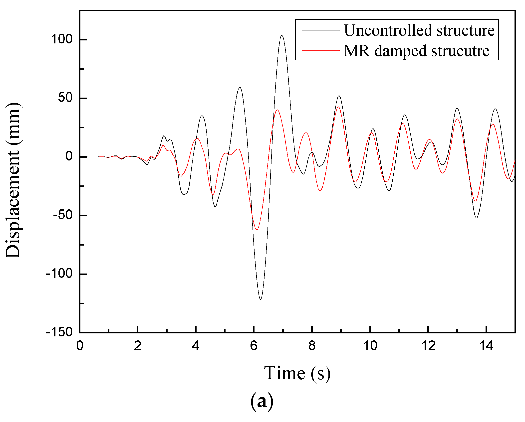
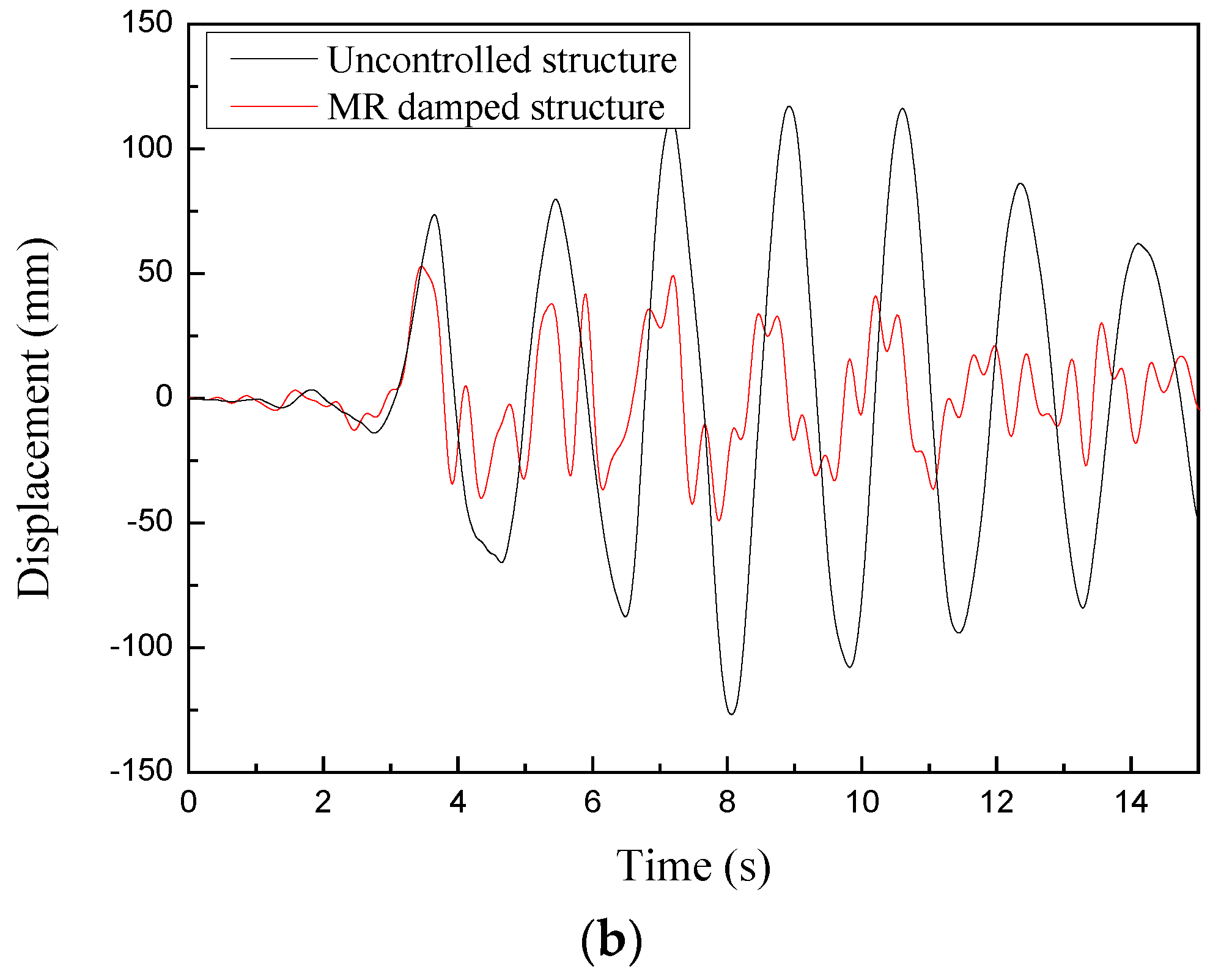
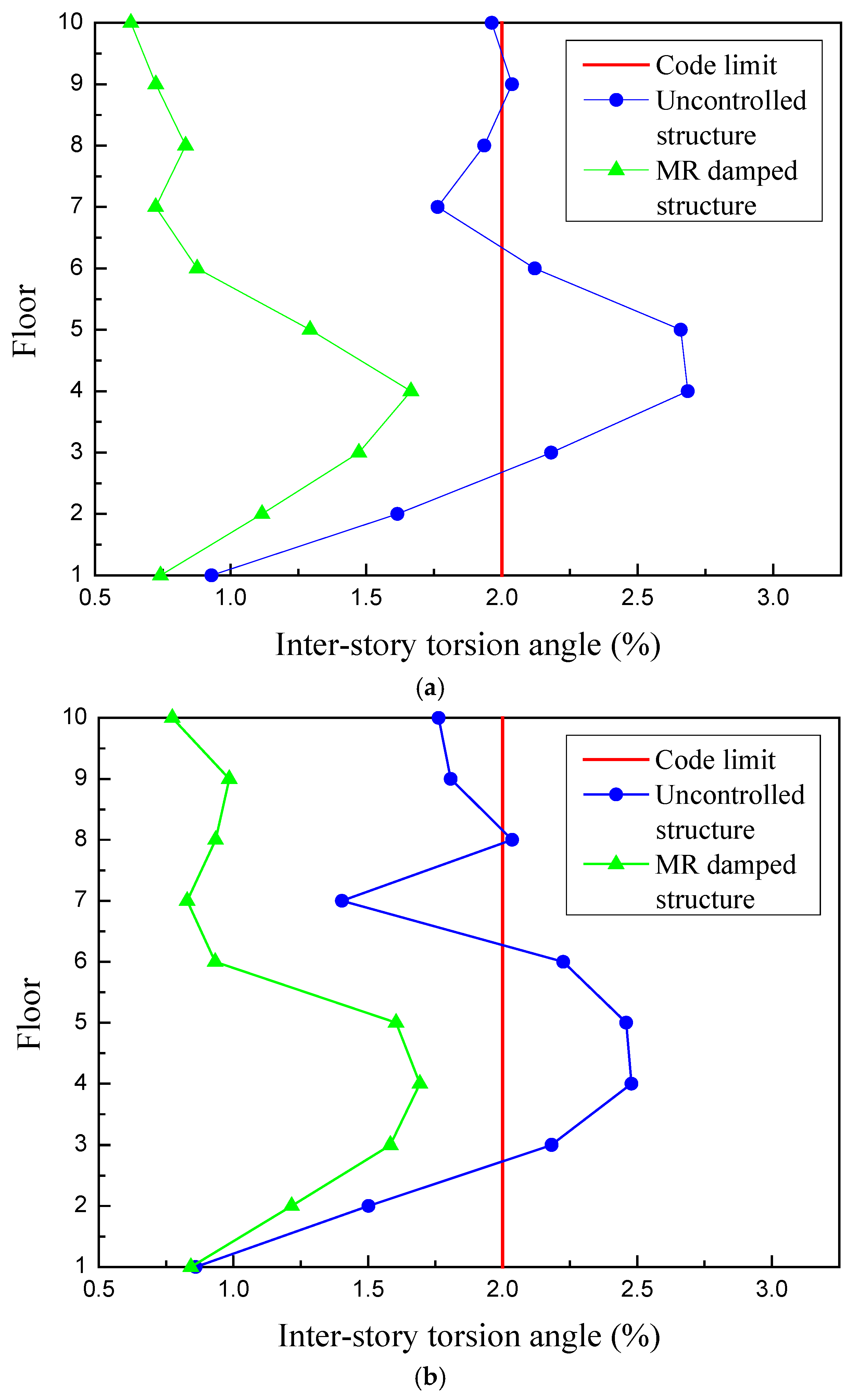
(2) The semi-active control system with multiple MR dampers using the proposed control strategy is numerically proven to be effective in mitigating both torsional and translational responses of eccentric structures. For translational vibration control, the acceleration and displacement time history responses have been significantly mitigated. For torsional vibration mitigation, the inter-story torsion angles are limited to 2% after the implementation of multiple MR dampers. The proposed cooperative control strategy for multiple MR dampers only needs two controllers, which is more economical and reliable, and thus has significant engineering application prospects for control systems with multiple MR dampers.

Author Contributions

Conceptualization, Y.Y. and Y.-Q.G.; methodology, Y.Y.; software, Y.Y.; validation, Y.Y. and Y.-Q.G.; formal analysis, Y.Y.; investigation, Y.Y.; resources, Y.Y.; data curation, Y.Y.; writing—original draft preparation, Y.Y.; writing—review and editing, Y.-Q.G.; visualization, Y.-Q.G.; supervision, Y.-Q.G.; project administration, Y.-Q.G.; funding acquisition, Y.-Q.G. All authors have read and agreed to the published version of the manuscript.

Funding

This research was funded by the Program of Chang Jiang Scholars of Ministry of Education, the Tencent Foundation through the XPLORER PRIZE, Ten Thousand Talent Program (Innovation Leading Talents), National Natural Science Foundation of China with Grant No. 51878355 and the program of China Scholarships Council (No. 202006090104) for the visiting at the National University of Singapore.

Institutional Review Board Statement

Not applicable.

Informed Consent Statement

Not applicable.

Data Availability Statement

Not applicable.

Conflicts of Interest

The authors declare no conflict of interest.

References

  1. Lin, J.L.; Tsai, K.C. Seismic analysis of two-way asymmetric building systems under bi-directional seismic ground motions. Earthq. Eng. Struct. Dyn. 2008, 37, 305–328. [Google Scholar] [CrossRef]
  2. De Stefano, M.; Pintucchi, B. A review of research on seismic behaviour of irregular building structures since 2002. Bull. Earthq. Eng. 2008, 6, 285–308. [Google Scholar] [CrossRef]
  3. Almazan, J.L.; Espinoza, G.; Aguirre, J.J. Torsional balance of asymmetric structures by means of tuned mass dampers. Eng. Struct. 2012, 42, 308–328. [Google Scholar] [CrossRef]
  4. Xu, Y.L.; Shum, K.M. Multiple-tuned liquid column dampers for torsional vibration control of structures: Theoretical investigation. Earthq. Eng. Struct. Dyn. 2003, 32, 309–328. [Google Scholar] [CrossRef]
  5. Mevada, S.V.; Jangid, R.S. Seismic response of torsionally coupled building with passive and semi-active stiffness dampers. Int. J. Adv. Struct. Eng. 2015, 7, 31–48. [Google Scholar] [CrossRef]
  6. Yao, J.T. Concept of structural control. J. Struct. Div. 1972, 98, 1567–1574. [Google Scholar] [CrossRef]
  7. Yang, J.N. Application of optimal control theory to civil engineering structures. J. Eng. Mech. Div. 1975, 101, 819–838. [Google Scholar] [CrossRef]
  8. Housner, G.; Bergman, L.A.; Caughey, T.K.; Chassiakos, A.G.; Claus, R.O.; Masri, S.F.; Skelton, R.E.; Soong, T.T.; Spencer, B.F.; Yao, J.T. Structural control: Past, present, and future. J. Eng. Mech. 1997, 123, 897–971. [Google Scholar] [CrossRef]
  9. Xu, Z.D.; Liao, Y.X.; Ge, T.; Xu, C. Experimental and theoretical study on viscoelastic dampers with different matrix rubbers. J. Eng. Mech. ASCE 2016, 142, 04016051. [Google Scholar] [CrossRef]
  10. Scerrato, D.; Giorgio, I.; Della Corte, A.; Madeo, A.; Dowling, N.E.; Darve, F. Towards the design of an enriched concrete with enhanced dissipation performances. Cem. Concr. Res. 2016, 84, 48–61. [Google Scholar] [CrossRef]
  11. Xu, Z.D.; Yang, Y.; Miao, A.N. Dynamic analysis and parameter optimization of pipelines with multidimensional vibration isolation and mitigation device. J. Pipeline Syst. Eng. Pract. 2021, 12, 04020058. [Google Scholar] [CrossRef]
  12. Yang, G.; Spencer, B.F., Jr.; Jung, H.J.; Carlson, J.D. Dynamic modeling of large-scale magnetorheological damper systems for civil engineering applications. J. Eng. Mech. 2004, 130, 1107–1114. [Google Scholar] [CrossRef]
  13. Xu, Z.D.; Sha, L.F.; Zhang, X.C.; Ye, H.H. Design, performance test and analysis on MR damper for earthquake mitigation. Struct. Control Health Monit. 2013, 20, 956–970. [Google Scholar] [CrossRef]
  14. Xu, Z.D.; Shen, Y.P.; Guo, Y.Q. Semi-active control of structures incorporated with magnetorheological dampers using neural networks. Smart Mater. Struct. 2003, 12, 80–87. [Google Scholar] [CrossRef]
  15. Yang, Y.; Xu, Z.D.; Guo, Y.Q. Seismic performance of magnetorheological damped structures with different MR fluid perfusion densities of the damper. Smart Mater. Struct. 2021, 30, 065008. [Google Scholar] [CrossRef]
  16. Jansen, L.M.; Dyke, S.J. Semiactive control strategies for MR dampers: Comparative study. J. Eng. Mech. 2000, 126, 795–803. [Google Scholar] [CrossRef]
  17. Kim, Y.; Langari, R.; Hurlebaus, S. Semiactive nonlinear control of a building with a magnetorheological damper system. Mech. Syst. Signal Processing 2009, 23, 300–315. [Google Scholar] [CrossRef]
  18. Weber, F. Semi-active vibration absorber based on real-time controlled MR damper. Mech. Syst. Signal Processing 2014, 46, 272–288. [Google Scholar] [CrossRef]
  19. Xu, Y.W.; Xu, Z.D.; Guo, Y.Q.; Zhou, M.; Zhao, Y.L.; Yang, Y.; Dai, J.; Zhang, J.; Zhu, C.; Ji, B.H.; et al. A programmable pseudo negative stiffness control device and its role in stay cable vibration control. Mech. Syst. Signal Processing 2022, 173, 109054. [Google Scholar] [CrossRef]
  20. Xu, Z.D.; Jia, D.H.; Zhang, X.C. Performance tests and mathematical model considering magnetic saturation for magnetorheological damper. J. Intell. Mater. Syst. Struct. 2012, 23, 1331–1349. [Google Scholar] [CrossRef]
  21. Xu, Z.D.; Guo, Y.Q. Fuzzy control method for earthquake mitigation structures with magnetorheological dampers. J. Intell. Mater. Syst. Struct. 2006, 17, 871–881. [Google Scholar] [CrossRef]
  22. Yoshida, O.; Dyke, S.J.; Giacosa, L.M.; Truman, K.Z. Experimental verification of torsional response control of asymmetric buildings using MR dampers. Earthq. Eng. Struct. Dyn. 2003, 32, 2085–2105. [Google Scholar] [CrossRef]
  23. Yoshida, O.; Dyke, S.J. Response control of full-scale irregular buildings using magnetorheological dampers. J. Struct. Eng. 2005, 131, 734–742. [Google Scholar] [CrossRef]
  24. Li, H.N.; Li, X.L. Experiment and analysis of torsional seismic responses for asymmetric structures with semi-active control by MR dampers. Smart Mater. Struct. 2009, 18, 075007. [Google Scholar] [CrossRef]
  25. Shook, D.A.; Roschke, P.N.; Lin, P.Y.; Loh, C.H. Semi-active control of a torsionally-responsive structure. Eng. Struct. 2009, 31, 57–68. [Google Scholar] [CrossRef]
  26. Bharti, S.D.; Dumne, S.M.; Shrimali, M.K. Earthquake response of asymmetric building with MR damper. Earthq. Eng. Eng. Vib. 2014, 13, 305–316. [Google Scholar] [CrossRef]
  27. Hu, Y.W.; Liu, L.F.; Rahimi, S. Seismic Vibration Control of 3D Steel Frames with Irregular Plans Using Eccentrically Placed MR Dampers. Sustainability 2017, 9, 1255. [Google Scholar] [CrossRef]
  28. Zafarani, M.M.; Halabian, A.M.; Behbahani, S. Optimal coupled and uncoupled fuzzy logic control for magneto-rheological damper-equipped plan-asymmetric structural systems considering structural nonlinearities. J. Vib. Control 2018, 24, 1364–1390. [Google Scholar] [CrossRef]
  29. Zafarani, M.M.; Halabian, A.M. Supervisory adaptive nonlinear control for seismic alleviation of inelastic asymmetric buildings equipped with MR dampers. Eng. Struct. 2018, 176, 849–858. [Google Scholar] [CrossRef]
  30. Zafarani, M.M.; Halabian, A.M. A new supervisory adaptive strategy for the control of hysteretic multi-story irregular buildings equipped with MR-dampers. Eng. Struct. 2020, 217, 110786. [Google Scholar] [CrossRef]
  31. Al-Fahdawi, O.A.S.; Barroso, L.R. Adaptive neuro-fuzzy and simple adaptive control methods for full three-dimensional coupled buildings subjected to bi-directional seismic excitations. Eng. Struct. 2021, 232, 111798. [Google Scholar] [CrossRef]
  32. Mazzoni, S.; McKenna, F.; Scott, M.H.; Fenves, G.L. Open System for Earthquake Engineering Simulation (OpenSEES) Command Language Manual [EB/OL]. Available online: http://opensees.berkeley.edu/wiki/index.php/Command_Manual (accessed on 10 July 2022).
  33. Zhao, J.; Li, K.; Zhang, X.C.; Sun, Y.P.; Xu, Z.D. Multidimensional vibration reduction control of the frame structure with magnetorheological damper. Struct. Control Health Monit. 2020, 27, e2572. [Google Scholar] [CrossRef]
  34. Chen, X.W.; Lin, Z. Structural Nonlinear Analysis Program Opensees Theory and Tutorial; China Architecture & Building Press: Beijing, China, 2014. [Google Scholar]
  35. Scott, B.D.; Park, R.; Priestley, M.J.N. Stress-strain behavior of concrete confined by overlapping hoops at low and high strain rates. J. Am. Concr. Inst. 1982, 79, 13–27. [Google Scholar]
  36. Taucer, F.; Spacone, E.; Filippou, F.C. A Fiber Beam-Column Element for Seismic Response Analysis of RC Structures; EERC Report 91/17; Earthquake Engineering Research Center, University of California: Berkeley, CA, USA, 1991. [Google Scholar]
  37. Ministry of Housing and Urban-Rural Development of People’s Republic of China; Code for Seismic Design of Buildings (GB50011-2010); China Architecture & Building Press: Beijing, China, 2010.
  38. Yang, Y.; Xu, Z.D.; Xu, Y.W.; Guo, Y.Q. Analysis on influence of the magnetorheological fluid microstructure on the mechanical properties of magnetorheological dampers. Smart Mater. Struct. 2020, 29, 115025. [Google Scholar] [CrossRef]
  39. Xu, Z.D.; Sun, C.L. Single-double chains micromechanical model and experimental verification of MR fluids with MWCNTs/GO composites coated ferromagnetic particles. J. Intell. Mater. Syst. Struct. 2021, 32, 1523–1536. [Google Scholar] [CrossRef]
  40. Vaiana, N.; Sessa, S.; Marmo, F.; Rosati, L. Nonlinear dynamic analysis of hysteretic mechanical systems by combining a novel rate-independent model and an explicit time integration method. Nonlinear Dyn. 2019, 98, 2879–2901. [Google Scholar] [CrossRef]
  41. Yang, Y.; Xu, Z.D.; Guo, Y.Q.; Sun, C.L.; Zhang, J. Performance tests and microstructure-based sigmoid model for a three-coil magnetorheological damper. Struct. Control Health Monit. 2021, 28, e2819. [Google Scholar] [CrossRef]
Figure 1. Typical floor plans of the ten-story L-shaped structure model. (a) 1st–6th floor (b) 7th–10th floor.
Actuators 11 00235 g001
Figure 2. Three-dimensional view of the full-scale spatial eccentric structure model.
Actuators 11 00235 g002
Figure 3. The spatial structure model with node numbers in SAP2000.
Actuators 11 00235 g003
Figure 4. Response comparisons of the structure model in OpenSEES and SAP2000. (a) Acceleration, (b) Displacement.
Actuators 11 00235 g004
Figure 5. Schematic diagram and performance tests of a single-coil MR damper.
Actuators 11 00235 g005
Figure 6. The vector diagram and the nephogram of the magnetic induction intensities of a single-coil MR damper with the excitation current of 2.0 A.
Actuators 11 00235 g006
Figure 7. Force–displacement and force–velocity curves. (a) Force–displacement curves. (b) Force–velocity curves.
Actuators 11 00235 g007aActuators 11 00235 g007b
Figure 8. The undetermined parameters of the sigmoid model.
Actuators 11 00235 g008
Figure 9. Comparisons between the damping force calculated from OpenSEES and performance test results. (a) 0.1 Hz, 20 mm. (b) 1.0 Hz, 0.4 A.
Actuators 11 00235 g009
Figure 10. Work flow diagram of the control system with multiple MR dampers.
Actuators 11 00235 g010
Figure 11. The placement of multiple MR dampers in different floors of the structure. (a) 1th–6th floor (b) 7th–10th floor.
Actuators 11 00235 g011
Figure 12. Acceleration time history responses of the uncontrolled and MR damped structure. (a) El Centro. (b) Taft.
Actuators 11 00235 g012
Figure 13. Displacement time history responses of the uncontrolled and MR damped structure. (a) El Centro. (b) Taft.
Actuators 11 00235 g013aActuators 11 00235 g013b
Figure 14. Schematic of the inter-story torsion angle.
Actuators 11 00235 g014
Figure 15. Inter-story torsion angles of the uncontrolled and MR damped structure. (a) El Centro. (b) Taft.
Actuators 11 00235 g015
Table 1. Comparisons of modal analysis results from OpenSEES and SAP2000.
ModeFrequency (Hz)Error (%)Participating Mass RatiosVibration Type
OpenSEESSAP2000UXUYRZ
11.09431.21069.610.000410.720.03633Translation vibration-Y
21.25491.34276.540.760.001020.00640Translation vibration-X
31.27061.39578.960.021750.001220.53Torsion vibration-Z
41.65301.843510.330.002690.001720.01864Torsion vibration-Z
51.82231.95446.760.002730.072930.11Coupled translation-torsion vibration
61.95662.17309.960.007750.025670.11Torsion vibration-Z
72.22892.22650.110.028722.267 × 10−50.01696Coupled translation-torsion vibration
82.70882.66661.580.005550.000530.00443Coupled translation-torsion vibration
Table 2. Basic properties of MR fluid.
Particle   Size   ( μ m ) Coating   Thickness   ( μ m ) Volume Fraction (%)Sedimentation Rate (%) Yield   Shear   Stress   τ y   ( kPa ) Viscosity
η (Pa.s)
1.50.015403.5 (120 days)7.5–10 (0.3 T)2–2.5
(25 mm/s)
Table 3. Dimensions of the MR damper.
Piston   Diameter   D (mm) Piston   Rod   Diameter   d (mm) Damping   Gap   h (mm) Working   Length   L t   ( mm )
11640280
Table 4. Modal analysis results of the MR damped structure.
ModeFrequency (Hz)Participating Mass RatiosVibration Type
UXUYRZ
11.38260.000410.8350.00271Translation vibration-Y
21.58600.79270.000820.00351Translation vibration-X
31.72650.018730.001220.0053Translation vibration-X
41.93080.002690.012320.00424Translation vibration-Y
52.27330.000730.072930.00033Translation vibration-Y
62.58600.000750.003160.6123Torsion vibration-Z
72.70020.008721.352 × 10−50.00056Translation vibration-X
82.95230.006140.000530.00043Translation vibration-X
Publisher’s Note: MDPI stays neutral with regard to jurisdictional claims in published maps and institutional affiliations.

