Abstract
This paper introduces a novel dual-drive micro-feeding system (DDMS) to obtain precise micro-feed synthetic motion by rotating both the screw and the nut, which eliminates the effects of nonlinear friction at low micro-feeding speeds and has good resistance to external disturbances. For the DDMS system, firstly, the frictional force of the screw–ball–nut contact surface is analyzed, and the dynamic system model based on the unique frictional coupling model is established for the DDMS. Secondly, a velocity squared term is added to the Stribeck model to characterize the influence of the frictional coupling on the system. The correctness of the modified model is verified through experiments and frictional parameters identification by combining with the genetic algorithm (GA). The dynamic trend of the frictional parameters with different speed combinations is studied, and the method of fitting parameters using the modified Stribeck model is proposed. Finally, the DDMS three closed-loop error compensation model and the proportional derivative position controller with the friction feedforward compensator are put forward to realize the accurate position-tracking function. Experiment results show that the method reduces the average tracking error by about 60% compared to the conventional PD controller.
1. Introduction
The ball screw is widely used in the linear feed system [1]. Its operation performance directly determines the accuracy of the machine. However, the ball screw pair is sensitive to external disturbance, and nonlinear frictional force makes accurate uniform displacement challenging to achieve [2], and there are problems such as significant dynamic error [3], complicated controller design, and severe hysteresis [4].
In order to obtain high-precision motion control, Prof. Feng proposed the dual-drive micro-feeding system (DDMS) [5,6], in which a permanent magnet synchronous motor (PMSM) is arranged for both the screw and the nut. These two motors rotate, and with the same direction and almost equal velocity are superimposed to achieve high-precision feeding of the driven worktable at ultra-low speed, and both the screw and the nut rotate at the speed outside the non-linear region, which eliminates the effect of non-linear friction at low speeds in both axes. The DDMS has two structural forms: hydraulic screw drive and ball screw drive. For the DDMS based on the hydrostatic screw nut pair, Su proposed a numerical model for the flow boundary for the hydrostatic screw [7], and Liu investigated the boundary slip characteristics within the hydrostatic screw under both DDMS and CFDS driving methods [8]. For the DDMS based on the ball screw nut pair, Yu performed a velocity spectrum analysis [9], Du proposed a full component friction identification model [10], and Wang investigated the effect of torque harmonics on the speed fluctuations of linear feed systems at low speeds; compared with CFDS, DDMS avoids the system resonance caused by torque harmonics at certain speed points [11]. These studies have demonstrated that the DDMS has better low-speed micro-feed performance than the conventional drive feeding system (CDFS). The research subject of this paper is mainly the DDMS based on the ball screw.
With the special mechanical structure, the DDMS is able to achieve micro-feed motion in a large stroke range with higher rigidity and driving force than existing macro-micro-composite stages, which is expected to be one of the future solutions for micro-nano motion. However, achieving this goal is also quite challenging, and this paper focuses on the following issues: in the DDMS, a certain given worktable speed can be combined in numerous ways with screw speed and nut speed in theory, the frictional force generated by different macroscopic speed combinations needs to be deeper studied, and the DDMS’s complete closed-loop compensation strategy also needs to be established for position control.
Friction is a complex nonlinear phenomenon in mechanical systems, which gives rise to problems such as static errors [12], limit loops, and stick-slip [13]. The Stribeck curve has been widely used as a classical static friction model, which can comprehensively describe the physical relationship between friction and motion velocity in a steady-state [14,15]. The Stribeck friction model integrates three aspects: Coulomb friction, viscous friction proportional to the motion velocity, and the Stribeck effect, which decreases exponentially with increasing velocity. This paper will modify the Stribeck model for the DDMS. The rest of this paper is organized as follows. A dynamic model considering the frictional coupling phenomenon is established in Section 2. The Stribeck friction model modified for the DDMS and the friction parameter dynamic change analysis are presented in Section 3. The fully closed-loop compensation method and controller design are described in Section 4. The results of the experiment are then analyzed in Section 5. Finally, the conclusions are drawn in Section 6.
2. Description and Modeling of System
2.1. System Description
The DDMS mechanical and control structure is shown in Figure 1. The worktable is equipped with a set of linear motion (LM) guideways, and a nut-driven helical linear feed unit is used. The screw axis uses a PMSM to drive its rotation through a coupling, and the nut axis is also driven by the other same motor through a synchronous toothed belt. When the DDMS is operated in differential speed mode, the two motors rotate in the same direction, and through the superposition of the two macro movements, the worktable feed motion is obtained. Although the screw and nut rotate in the same direction at this time, the speed direction of the two motors are opposite in their servo drivers, which is determined by the positive direction of the worktable when one of the axes rotates alone. To avoid ambiguity, the synthetic speed is used instead of differential speed in this paper.
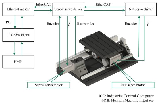
Figure 1.
Block diagram of the DDMS.
The following definitions are given: the side with the larger absolute speed of the screw or nut is called the main drive axis, of which the speed is called the active speed. The side with the lower absolute speed is called the slave axis, of which the speed is called the base speed . The speed of the worktable is the synthetic speed . Due to the large inertia of the nut, the nut rotates at a constant speed while changing the screw speed to improve the system’s stiffness and achieve high-precision feed motion. The DDMS is converted to the CDFS when the slave axis speed is zero.
2.2. Frictional Coupling Model
When the DDMS is in differential feed mode, the screw and nut both rotate in the same direction. The force analysis of the screw–ball–nut contact surface with the simplified schematic diagram is shown in Figure 2, taking the screw axis as the active axis. represents the friction force, represents the object applying the force, represents the object receiving the force, represents the screw rotation speed, represents the nut rotation speed, is the ball’s self-rotation angular speed, is the ball’s public revolution angular speed, and is the output torque of the PMSM.
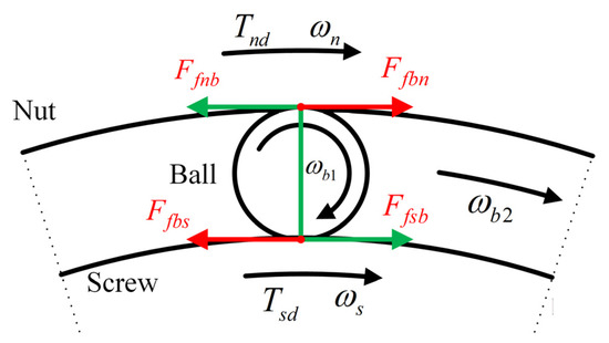
Figure 2.
Force analysis of the screw–ball–nut contact surface.
When the absolute speed of the screw motor is larger than the nut motor, the friction force of the screw and the nut on the ball will jointly form a moment of force so that the ball on the one hand self-rotates, and the public rotates around the center of screw on the other hand. The reaction force of the ball on the screw is an impede moment for the screw shaft, but the reaction force of the ball on the nut is an increased moment for the nut axis. The phenomenon of different positive and negative work done by the ball on the screw and the nut is called the frictional coupling model. Replace linear friction with rotary friction (). Due to the complex motion of the ball and the special structure of the DDMS, the relationship between and is not discussed in this paper. When the absolute speed of the screw is larger, in order to maintain the public rotation of the ball has:
when the absolute velocity of the nut is larger:
Therefore, is a segmentation function that depends on which is the active axis of the screw or the nut. The reason for the formation of the segmentation function is different from the difference between the forward and reverse friction parameters in CDFS.
2.3. Dynamical Model
Figure 3 shows the dynamics model of the DDMS. Based on the frictional coupling analysis, the simplified dynamics model of the DDMS based on Newton’s second law can be written as:
where is the axis rotational displacement, is the output torque of the axis motor, is the axis support bearing and PMSM friction, is ball–screw or ball–nut contact surface friction, is the rotational inertia, is the ratio of linear motion to rotary motion, is the ratio of rotary motion to linear motion, is the worktable displacement, is the bench quality, is the friction between worktable, and LM guideways, is external disturbances. Rotational speed and linear speed can be converted by the following equation:
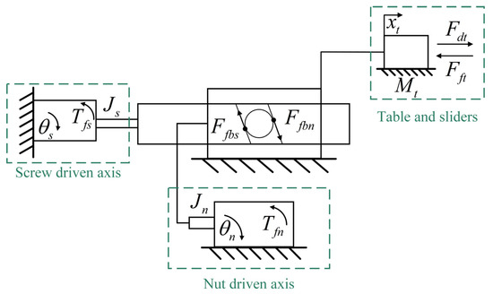
Figure 3.
Dynamic model of the DDMS.
2.4. Dynamical Model Analysis
When the DDMS is in a quasi-stationary state with differential speed, i.e., , if the absolute value of the screw speed is increased, as can be seen from the Equation (3), the output torque of the screw motor will increase significantly, which is mainly caused by two aspects, on the one hand, the friction of the ball on the screw (), and on the other hand, the friction between the worktable and LM guide (). Meanwhile, the absolute value of the output torque of the nut motor decreases because the ball performs positive work on the nut, and the required friction force is certain when the nut speed remains constant. If the screw speed continues to rise, the relative speed between the screw–ball–nut contact surface also increases, which will cause the friction force between the ball and the nut contact surface to gradually increase. The centrifugal force’s growth rate is also gradually increasing, for the centrifugal force is generally proportional to the quadratic speed. However, the speed of the nut at this time is still unchanged, so the total torque required by the nut at this time remains unchanged. The friction force becomes larger, meaning that the absolute value of the output torque of the nut motor will continue to decline, and the speed of decline is increasingly fast. For the screw shaft, the analysis is similar to that of the nut shaft and will not be elaborated.
Due to the existence of the frictional coupling model, when the manufacturing and assembling errors of DDMS itself cause the friction force changes on the contact surface of the screw–ball–nut, the opposite effect of the friction on the screw or nut from the ball will lead to fluctuations in the synthesis speed of the worktable, so the effect of frictional coupling on the system should be considered in the friction model and controller.
In addition, when the base speed is different, the rotational potential energy of the screw and nut is different, and the system’s stiffness is bound to change. Theoretically, the greater the base speed, the greater the stiffness and the stronger the ability to resist external disturbances, which is urgently what we need. However, when the base speed is enormous, which causes significant tracking errors because the displacement fluctuation of the screw and nut at a higher speed will be bigger than at a lower base speed, which affects the worktable displacement. Meanwhile, too low a reference speed will cause the screw and nut axis to run in the non-linear region, which will also increase the tracking error. Therefore, selecting the required base speed for different synthesis speeds is an essential part of the DDMS to complete the high-precision uniform speed feeding. Since the impact of the base speed on the system needs to be further explored, the theory of the choice of the base speed is not discussed in this paper; however, the effect of the base speed on the friction parameters is studied as a basis for future research.
The principle of formation shows that it is not only a function of the synthesis speed () but also has a connection with the base speed (). As the base speed will add a revolution speed to the ball to cause a change in centrifugal force, which affects the friction force, in addition, as mentioned earlier, when the active axis is not the same, will also make a difference. Due to the introduction of , the composition of the frictional forces is divided in a more detailed way, and the dynamical model presents a higher complexity. The excessive amounts of unknowns make it impossible to separate and identify each part of the frictional force, which is unfortunate. However, it is still feasible to design controllers for friction compensation if a suitable model for the total friction of the screw and nut shafts can be found.
3. Friction Identification
3.1. Genetic Algorithms
The genetic algorithm [16,17] is a computational model of the biological evolution process that simulates the mechanism of natural selection and genetics of Darwin’s biological evolution theory. The algorithm converts the problem-solving process into a process similar to the crossover and mutation of chromosomal genes in biological evolution by using computer simulation operations in a mathematical way. In solving more complex combinatorial optimization problems, it is usually able to obtain better optimization results faster than some conventional optimization algorithms [18]. For example, compared with the simulated annealing algorithm (SA), GA has a faster convergence speed and its performance is relatively less affected by the initial value and related parameters. Another typical algorithm is the particle swarm optimization (PSO) algorithm, but it is easy to fall into local optimum, resulting in low convergence accuracy, and it is not easy to converge and cannot effectively solve discrete and combinatorial optimization problems. Therefore, the GA algorithm is chosen for parameter fitting in this paper.
3.2. Frictional Model at a Constant Base Speed
The friction model mainly includes the static friction model and dynamic friction model, where the dynamic friction model is mainly used for the pre-slipping stage. This paper does not consider the dynamic friction model of the DDMS, so the friction memory and other dynamic friction characteristics can be ignored. Converting rotational friction to linear friction when discussing friction.
Stribeck friction model, as a classical static friction model, can be a suitable modulus of the relationship between speed and friction during steady-state motion and has been widely used. Its primary expression is as follows [14]:
where is Coulomb friction, is coefficient of viscous friction, is maximum static friction, the exponential term is used to describe the Stribeck effect, is used to control the shape of the Stribeck curve. In this paper, , is the symbolic function, and the specific expressions are as Equation (12):
The analysis in Section 2.4 shows that the frictional force of the screw–roller–nut contact surface is vital in the high-precision control of the system. In order to characterize the change in friction caused by the centrifugal force of the ball at different worktable speeds (), the Stribeck model is modified for the DDMS reference in the paper [19]. When the ball screw reaches a steady state of speed, the centrifugal force is proportional to the quadratic of the speed, so the frictional force change caused by the centrifugal force can be written as Equation (13):
where is the friction caused by centrifugal force, is the friction coefficient of the leader–ball–nut contact surface, is the centrifugal force coefficient, which is related to the amount, material, diameter and contact angle of ball. Add Equation (13) to Equation (11), the modified Stribeck model can be described as follows:
where is the coefficient of frictional influence due to centrifugal force. For the friction model adopted, the desired parameter vector in GA can be defined as [20,21]:
when the worktable speed is , the system friction identification error can be defined as:
where is the experimentally measured steady-state friction, and denotes the estimated steady-state friction that is calculated using Equation (14). The optimized cost function is defined as follows:
where is the number of data points included in each experiment.
In the GA, there are four parameters that need to be set, which are population size, number of generations of terminated evolution, probability of crossover, and probability of mutation. The parameters are selected as follows: (1) When the population size is too small, it is obvious that inbreeding will occur and produce pathological genes, and when the population size is too large, the results are difficult to converge and waste resources, and the robustness decreases. The empirical value of the population size is taken as 20~200. (2) If the number of evolutionary generations is too small, the algorithm does not converge easily and the population is not yet mature; if the number of evolutionary generations is too large, the algorithm has already converged or the population is too precocious to converge, so it is meaningless to continue the evolution, which will only increase the time expenditure and waste of resources. The empirical value of the number of generations of terminated evolution is taken as 100~500. (3) If the crossover probability is too small, the algorithm cannot update the population effectively, and if the probability of crossover is too large, although the diversity of the population can be guaranteed, the probability of higher-order patterns being destroyed increases. The empirical value of the probability of crossover is taken as 0.4~0.99. (4) Similar to the probability of crossover, too large a mating probability can easily destroy the existing favorable patterns, increase the randomness, and easily miss the optimal individuals; too small a mating probability cannot effectively renew the population. The empirical value of the probability of mutation is taken as 0.0001~0.1. In this paper, a large computation can be tolerated for obtaining sufficiently accurate results, therefore, the population size is chosen to be 150, and the number of generations of terminated evolution is 500. In order to avoid algorithmic search stagnation and ensure the stability of the algorithm, the crossover probability is chosen to be 0.8, and the variation probability is 0.05.3.3. Dynamic variation model of friction parameters.
In the DDMS, for a given worktable speed (), there are theoretically an infinite number of speed combinations, and the friction parameters variate in different base speeds, so it is necessary to study the dynamic changes of friction parameters at different base speeds. The following Equation (19) is used to characterize the simplified friction model while discussing the dynamic variation of the friction parameters:
For parameters , , they characterize the friction of the screw axis and nut axis at different worktable speeds with a constant base speed. The following analyses is that DDMS operated at the same worktable speed with different base speeds. (1) The curves of frictional force of the screw () and nut () are the Stribeck model (2) the change in friction of the screw–roller–nut contact surface caused by centrifugal force at different base speeds should be linearly related to the square of the base speed; (3) in different base speeds, the frictional force of the worktable at a certain speed can be regarded as a constant.
These analyses show that the dynamic variation of each parameter contains a constant term, a velocity viscous damping term, an exponential term for the Stribeck effect, and a frictional term due to centrifugal force. Therefore, the dynamic change model of the parameters at different base speeds are the same as the modified Stribeck model shown in Equation (20). In order to differentiate the variables, the following equation is used for fitting:
where . Similar to the previous, its error calculation function and expectation function in GA are not elaborated in this paper.
4. Controller Design
Due to the unique structure of the DDMS, the worktable’s displacement is the synthesis of the screw and the nut displacements; for a given worktable speed , the target speeds of the screw and nut are , , respectively, satisfying:
The actual speed of the screw axis and the nut axis are , , and the tracking error of the screw and the nut () can be written as
where , the worktable displacement tracking error () is:
As the positions of both the screw and nut axes affect the worktable displacement, the worktable displacement error not only contains the displacement tracking error of the screw and nut but also includes the displacement error caused by the pitch error, so the worktable position tracking error can also be written as:
Since , have been compensated in both axes of the screw and nut, there is no need to feed back to one of the two axes again in the form of error, or in a certain proportion, but only to compensate for as follows:
Due to the small inertia of the screw axis, the pitch error is fed back to the screw for compensation, and the total tracking error of the two axes can be written as:
Take Equations (21)–(26) into Equation (27), and Equation (28) can be acquired:
In the DDMS, a feedforward control method can be used to improve the system‘s tracking performance. When the closed-loop system is continuous, let the product of the feedforward link and the closed-loop system transfer function be equal to one, so as to achieve the complete reproducing input [22,23,24]. The constructed control block diagram based on PD with friction feedforward is shown in Figure 4. In the control block, according to paper [25,26], the PMSM’s electromagnetic torque is simplified by using magnetic field directional control as follows:
where is the number of primary pole pairs, is the permanent magnet flux linkage, is the thrust current, is the thrust coefficient.
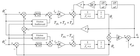
Figure 4.
Control block diagram of PD with feedforward friction compensation.
5. Experiment and Results
5.1. Experimental Equipment
The schematic diagram and photos of the experimental equipment are shown in Figure 5. The feed drive with a stroke of 280 mm is equipped with a ball screw (DIR 1605, THK) with a diameter of 16 mm. The ball screw is driven by two PMSMs (Panasonic MHMF042LV2M) with a rated power of 400 W, and the rated torque is 1.27 . The motor is equipped with a high-resolution rotary encoder (23 bits) to provide motor position feedback and is connected to the servo driver (Panasonic MBDLT25BF), which communicates with the industrial control computer (ICC) via EtherCAT protocol. A raster ruler with a 10 nm resolution scale (KEYENCE GVS 600T) is used to measure the worktable position, and it is connected to the screw servo driver, of which external sensor monitoring function is enabled to read the raster ruler pulse data for fully closed-loop control at the ICC. An environment of Windows10+VS+QT in the ICC is used to develop the control software, with which secondary development of KRMotion is performed using the process data object (PDO) function to read motor position, speed, torque, and external raster ruler data directly, with a sampling frequency of 4 kHz and a control period set to the same as the sampling period, i.e., 250 us. KRMotion is a real-time motion controller developed by the Shandong E-Code company based on the German Kithara real-time suite (KRTS) [27,28]. The interface of ICC software developed is shown in Figure 6. The specific parameters of the experimental equipment are shown in Table 1.
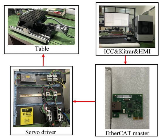
Figure 5.
Experimental equipment.
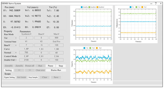
Figure 6.
ICC software interface.

Table 1.
Experimental equipment parameters.
5.2. Estimation of Frictional Parameters at a Constant Base Speed
Experiment was conducted on a constant base speed with different worktable speed, in order to avoid screw and nut running in the non-linear area, so a larger base speed is selected . Take the experimental sequence as follows:
The frictional data obtained were fitted using the GA, and the experimental and estimation frictional curves of the screw and the nut are shown in Figure 7. The results of the fitted parameters are shown in Table 2.
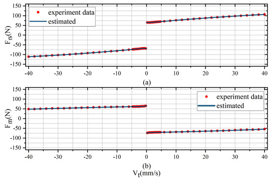
Figure 7.
Experimental and estimation of frictional curves at a constant base speed with different worktable speed. (a) Screw frictional force curve; (b) Nut frictional force curve.
Table 2.
Frictional parameters identification results.
As can be seen from Figure 7, after crossing the Stribeck inflection point, the linearity of the output torque of the screw and nut motors is not ideal. However, the velocity model considering the effect of centrifugal force and base speed can fit the curve nicely. Table 3 lists the fitting errors with and without the addition of the quadratic velocity term of centrifugal force, and the evaluation using sum of squares for error (SSE) shows a minimum accuracy improvement of 29.8%, and root mean squared error (RMSE) shows a minimum accuracy improvement of 19.4%. In addition, the sign of the coefficients indicating the rate of growth/slowing trends of the total frictional force is also consistent with the previous analysis in Section 2.4, so it is necessary to consider the change in frictional force due to centrifugal force in the DDMS.
Table 3.
Comparison of estimated errors.
5.3. Estimation of Dynamic Changes of Frictional Parameters
Experiments are conducted at different base speeds to study the trend of frictional parameters of the screw and nut axes. The experimental sequences are as follows (unit: ):
From the previous analysis, it can be seen that the frictional force fluctuation between the contact surface of the screw ball nut will lead to a large tracking error. In order to reduce the fluctuation in the overall frictional force ratio, the preload of the screw and nut support bearing is increased to improve the system stiffness. For each group of experiments, the GA is used to fit, and the dynamic variation curves of frictional parameters are shown in Figure 8.
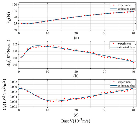
Figure 8.
Dynamic variation curves of frictional parameters. (a) Variation curve of Coulomb frictional coefficient () with base velocity. (b) Variation curve of viscous frictional coefficient () with base velocity. (c) Variation curve of centrifugal force coefficient () with base velocity.
It can be seen that the frictional parameters show a Stribeck curve with the base speed, which proves the correctness of the proposed model. It is noted that the and critical speeds () are approximately the same, reflecting the gradual transition of the screw shaft as the base speed increases. It should be noted that the Coulomb frictional force here is the sum of total frictional force required for the screw axis () at this base speed, the Coulomb frictional force () between worktable and LM guideways, and the screw–balls contact surface Coulomb frictional force (), so it is reasonable that the Coulomb frictional force increases as the base speed increases, but the true meaning of the Coulomb frictional force here has changed. The prediction of the change curve for each parameter is again performed using the genetic algorithm. The fitting results are shown in Table 4, and parameters for both axes of the nut and the screw are included.
Table 4.
Fitting results of dynamic variation for frictional parameters.
5.4. Friction Compensation
Keep the nut speed at a constant to increase the stiffness of the system and superimpose the sinusoidal variable speed motion on the base speed of the screw axis to obtain the sinusoidal motion of the worktable. Experimental sequences are as follows:
The tracking error of using PD with FF and PD controllers alone is shown in Figure 9; the comparisons of tracking errors are shown in Table 5. It can be seen that the proposed controller and the error compensation method play a nice effect, the average tracking error is reduced by 60% and the peak is reduced by 70%.
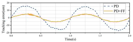
Figure 9.
Tracking error curves of PD with friction feedforward compensation and PD alone.
Table 5.
Comparisons of tracking errors.
6. Conclusions
- (1)
- By analyzing the force on the contact surface of the screw–ball–nut, the unique frictional force coupling model is introduced and further reveals the factors affecting the feeding accuracy of the DDMS and constructs a system dynamics model considering the frictional coupling.
- (2)
- The experiments demonstrate the correctness of adding the velocity squared term to the Stribeck model, which improves the fitting accuracy by at least 29.8% in SSE and 19.4% in RMSE compared with no squared term. Subsequently, the trends of the frictional parameters with the dynamics of the base speeds are obtained experimentally, which reveals the frictional characteristics of the DDMS further. The modified frictional model proves that the frictional force changed by the centrifugal force in the frictional coupling model and different base speeds are necessary considerations for the design of the DDMS system controller.
- (3)
- The fully closed-loop compensation model is proposed for the DDMS to realize three closed-loop controls of the screw axis, nut axis, and worktable. A PD + FF controller is designed to improve the position tracking accuracy, and the experimental result shows a 60% improvement in accuracy compared to the conventional PD controller, which effectively proves the correctness of the modified frictional model, parameters identification, and error compensation methods.
Author Contributions
Conceptualization, Z.L. and X.F.; methodology, Z.L and X.F.; software, Z.L. and M.Y; validation, Z.L.; formal analysis, Z.L. and X.F.; investigation, Z.S.; resources, X.F., Y.L and M.Y.; data curation, Z.L. and Z.S.; writing—original draft preparation, Z.L.; writing—review and editing, Z.L., X.F., Z.S., Y.L. and M.Y.; visualization, Z.L. and Y.L.; supervision, X.F.; project administration, X.F.; funding acquisition, X.F. All authors have read and agreed to the published version of the manuscript.
Funding
This research is funded by the National Natural Science Foundation of China, grant number 51875325; the Natural Science Foundation of Shandong Province, China, grant number ZR2019MEE003; and the Key R&D Program of Shandong Province, China, grant number 2022CXGC010101.
Institutional Review Board Statement
Not applicable.
Informed Consent Statement
Not applicable.
Data Availability Statement
Not applicable.
Conflicts of Interest
The authors declare no conflict of interest. The funders had no role in the design of the study; in the collection, analyses, or interpretation of data; in the writing of the manuscript, or in the decision to publish the results.
References
- Kamalzadeh, A.; Gordon, D.J.; Erkorkmaz, K. Robust compensation of elastic deformations in ball screw drives. Int. J. Mach. Tools Manuf. 2010, 50, 559–574. [Google Scholar] [CrossRef]
- Wang, Y.F.; Wang, D.H.; Chai, T.Y. Modeling and control compensation of nonlinear friction using adaptive fuzzy systems. Mech. Syst. Signal Process. 2009, 23, 2445–2457. [Google Scholar] [CrossRef]
- Jie, L.; Fugui, X.; Xinjun, L.; Bin, M.; Zeyuan, D. Analysis on the Research Status of Volumetric Positioning Accuracy Improvement Methods for Five–Axis NC machine Tools. J. Mech. Eng. 2017, 53, 113–128. [Google Scholar]
- Xiang, H.; Qiu, Z.; Li, X. Simulation and experimental research of non–linear friction compensation for high–precision ball screw drive system. In Proceedings of the 2009 9th International Conference on Electronic Measurement & Instruments, Beijing, China, 16–19 August 2009. [Google Scholar]
- Hanwen, Y.; Feng, X. Modelling and analysis of dual driven feed system with friction. J. Balk. Tribol. Assoc. 2015, 21, 736–752. [Google Scholar]
- Wang, Z.; Feng, X.; Li, P.; Du, F. Dynamic modeling and analysis of the nut-direct drive system. Adv. Mech. Eng. 2018, 10, 1687814018810656. [Google Scholar] [CrossRef]
- Su, Z.; Feng, X.; Li, H.; Lu, J.; Wang, Z.; Liu, Y. Boundary–Adapted Numerical Modeling of Flow in a Hydrostatic Leadscrew. Actuators 2021, 10, 190. [Google Scholar] [CrossRef]
- Liu, Y.; Feng, X.; Li, Y.; Lu, J.; Su, Z. Research on boundary slip of hydrostatic lead screw under different driving modes. Sci. Rep. 2021, 11, 22307. [Google Scholar] [CrossRef]
- Yu, H.W.; Feng, X.Y. Dynamic Modeling and Spectrum Analysis of Macro-Macro Dual Driven System. J. Comput. Nonlinear Dyn. 2016, 11, 044505. [Google Scholar] [CrossRef]
- Du, F.; Zhang, M.; Wang, Z.; Yu, C.; Feng, X.; Li, P. Identification and compensation of friction for a novel two–axis differential micro–feed system. Mech. Syst. Signal Processing 2018, 106, 453–465. [Google Scholar] [CrossRef]
- Wang, Z.G.; Feng, X.Y.; Du, F.X.; Li, H.; Su, Z. A novel method for smooth low–speed operation of linear feed systems. Precis. Eng. 2019, 60, 215–221. [Google Scholar] [CrossRef]
- Olsson, H.; Astrom, K.J.; de Wit, C.C.; Gafvert, M.; Lischinsky, P. Friction Models and Friction Compensation. Eur. J. Control 1998, 4, 176–195. [Google Scholar] [CrossRef]
- Tan, K.K.; Lee, T.H.; Huang, S.N.N.; Jiang, X. Friction Modeling and Adaptive Compensation Using a Relay Feedback Approach. IEEE Trans. Ind. Electron. 2001, 48, 169–176. [Google Scholar]
- Lu, X.; Khonsari, M.M.; Gelinck, E.R.M. The Stribeck Curve: Experimental Results and Theoretical Prediction. J. Tribol. 2006, 128, 789–794. [Google Scholar] [CrossRef]
- Woydt, M.; Wäsche, R. The history of the Stribeck curve and ball bearing steels: The role of Adolf Martens. Wear 2010, 268, 1542–1546. [Google Scholar] [CrossRef]
- Tang, X.H.; Chang, X.; Fang, Z.F. The Enhanced Genetic Algorithms for the Optimization Design. In Proceedings of the 2010 3rd International Conference on Biomedical Engineering and Informatics, Shenyang, China, 16–18 October 2010; Volume 1–7, pp. 2990–2994. [Google Scholar]
- Xu, J.; Liu, L.; Xu, W.B. Application of immune genetic algorithm to multiobjective optimization. In Proceedings of the International Symposium on Distributed Computing and Applications to Business, Engineering and Science, Hangzhou, China, 12–15 October 2006; Volume 1–2, pp. 1048–1050. [Google Scholar]
- Konak, A.; Coit, D.W.; Smith, A.E. Multi-objective optimization using genetic algorithms: A tutorial. Reliab. Eng. Syst. Saf. 2006, 91, 992–1007. [Google Scholar] [CrossRef]
- Zhuo, Y.; Zhou, X. Dynamic Characteristic Analysis of High-speed Spherical Ball Bearing. J. Mech. Eng. 2015, 51, 37–46. [Google Scholar] [CrossRef]
- Du, F.; Feng, X.; Li, P.; Yue, M.; Wang, Z. Modeling and Analysis for a Novel Dual-axis Differential Micro-feed System. J. Mech. Eng. 2018, 54, 195–204. [Google Scholar] [CrossRef]
- Liu, D.P. Research on parameter identification of friction model for servo systems based on genetic algorithms. In Proceedings of the 2005 International Conference on Machine Learning and Cybernetics, Guangzhou, China, 21 August 2005; Volume 1–9, pp. 1116–1120. [Google Scholar]
- Jamaludin, Z.; Van Brussel, H.; Swevers, J. Friction Compensation of an XY Feed Table Using Friction–Model–Based Feedforward and an Inverse–Model–Based Disturbance Observer. IEEE Trans. Ind. Electron. 2009, 56, 3848–3853. [Google Scholar] [CrossRef]
- Li, Z.J.; Su, C.Y.; Wang, L.Y. Nonlinear Disturbance Observer—Based Control Design for a Robotic Exoskeleton Incorporating Fuzzy Approximation. IEEE Trans. Ind. Electron. 2015, 56, 5763–5775. [Google Scholar] [CrossRef]
- Strijbosch, N.; Tiels, K.; Oomen, T. Hysteresis Feedforward Compensation: A Direct Tuning Approach Using Hybrid-MEM-Elements. IEEE Control Syst. Lett. 2022, 84, 102804. [Google Scholar] [CrossRef]
- Li, L.B.; Sun, L.L.; Zhang, S.Z.; Yang, Q.Q. Speed tracking and synchronization of multiple motors using ring coupling control and adaptive sliding mode control. ISA Trans. 2015, 58, 635–649. [Google Scholar] [CrossRef]
- Zhong, L.; Rahman, M.F.; Hu, W.Y.; Lim, K.W. Analysis of direct torque control in permanent magnet synchronous motor drives. IEEE Trans. Power Electron. 1997, 12, 528–536. [Google Scholar] [CrossRef]
- Liu, Y.; Ni, H.; Zhang, C.; Wang, Y.; Sun, H. PC—based open control platform design of integration of machine vision and motion control. J. Zhejiang Univ. Eng. Sci. 2016, 50, 1381–1386. [Google Scholar]
- Schwager, J. Review of Real—Time Ethernet interfaces. Elektronik 2009, 58, 42–43. [Google Scholar]
Publisher’s Note: MDPI stays neutral with regard to jurisdictional claims in published maps and institutional affiliations. |
© 2022 by the authors. Licensee MDPI, Basel, Switzerland. This article is an open access article distributed under the terms and conditions of the Creative Commons Attribution (CC BY) license (https://creativecommons.org/licenses/by/4.0/).