Abstract
This paper begins with a quick survey of potential space applications and a brief review of previous experiments on the shape control of a spherical shell reflector with a thin film of PVDF-TrFE. Next, the problem of thermal sensitivity is addressed numerically; it is found that, because of the large thermal expansion of the active material, the surface figure error generated by a linear thermal gradient on a unimorph reflector is considerable and its correction requires large control voltages. The surface figure accuracy can be greatly improved by a balanced design (i.e., adding a passive layer symmetrical to the PVDF-TrFE layer) and using a low CTE substrate. Finally, the paper considers a petal reflector; the unimorph design is even more sensitive than the full reflector to the thermal gradient, but the balanced design turns out to be better than the full reflector, both from the point of view of the surface figure error and the control voltages.
1. Introduction
The surface figure accuracy of space reflectors must be maintained to a fraction of the wavelength in spite of the manufacturing and deployment errors, gravity gradient and thermal loads. The thermoelastic loads due to thermal gradients often constitute the main contributor to the shape distortion, especially in LEO (Low Earth Orbit), because of the frequent eclipses, which induce unsteady thermal loads [1]. The jitter induced by the attitude control wheels are the main disturbance to the pointing stability.
1.1. Large Reflectors
The goal of using larger reflectors in space is to improve the sensitivity and resolution of antennas, spectrographs and imaging devices while meeting the volume and weight constraints of the launcher. When the limited space in the fairing of the launcher does not allow a rigid reflector, folding is necessary during the launch and the reflector is unfolded once in orbit. This brings the challenge of maintaining the surface figure accuracy of the deployed reflector for the mission, which is becoming increasingly difficult as the wavelength becomes shorter (RMS wavefront accuracy of for optical systems). This often requires some kind of active control. The weight constraints associated with launching large reflectors to distant operating locations such as the Lagrange L2 point brings another requirement on the low areal density.
The James Webb telescope with a primary mirror of 6.5 m relies on articulated rigid segmented mirrors. Several alternative concepts of deployable reflectors with low areal density (<3 kg/m) and high stowability have been proposed: Lenticular pressure stiffened membranes [2]; and doubly curved form stiffened elastic shells [3,4]. None of them offer accuracy acceptable in the optical range. Others rely on a deployable mesh antenna supporting a membrane reflector controlled by a set of electrostatic actuators [5].
Our work [6,7] investigates the control a thin spherical polymer shell covered with a thin film of electrostrictive copolymer (PVDF-TrFE) used as in-plane strain actuator (according to the mode); the target shape is obtained by applying voltages to a set of independent electrodes. Earlier work has shown that strain actuators are very efficient to control a flat plate; they are widely used in Adaptive Optics (AO) (e.g., see [8]). However, the response of a thin spherical shell is far more complicated; the accurate shape control requires that the electrode size be such that
where is the radius of curvature and t is the shell thickness [9,10]. Any significant departure from this condition will lead to a wavy reflector shape at the transition between electrodes excited with different strains (i.e., different voltages for an electrostrictive material). According to the foregoing equation, assuming electrodes with an aspect ratio close to 1, the number of electrodes N follows ; thus, more curvature and thinner shell will mean more electrodes, more sophisticated metrology and more complex control algorithms.
1.2. Small Satellites
In recent years, low-cost small satellites and cubesats have become increasingly popular for Earth observation, inter-satellite laser communication and LIDAR (e.g., [11,12]). The performance of these systems depends critically on the reflector size, and they can greatly benefit from using deployable light collectors much larger than the satellite itself, provided however that the imaging quality can be maintained with a deployable mirror. A passive Ka-band radar deployable antenna of 0.5 m has been demonstrated at JPL on a 6U cubesat [13]. Attempts to use deployable reflectors made of four rigid petals for optical applications have also been reported (e.g., [14,15]). In contrast, our goal is an actively controlled flexible deployable reflector.
Optical communication allows wider data transfer bandwidth, but requires greater precision. The transmission gain G of laser communication (e.g., [16]) is directly proportional to
where is the gain of the transmitting aperture and that of the receiver. accounts for the imperfection of the transmitter if not perfectly diffraction limited (the imperfection in the wavefront is usually accounted for by the Strehl ratio , where is the RMS wavefront error expressed in radian). Similarly, accounts for the imperfection of the receiver. Assuming the same aperture for the transmitter and the receiver, Equation (2) suggests that, providing the optical quality of the telescopes can be maintained, the transmission gain is a function of the fourth power of the aperture.
Figure 1 shows a conceptual view of a deployable reflector with flexible petals, in folded (left) and deployed (right) configurations. The Figure illustrates the deployment with a simple translation mechanism moving the reflector outside the cubesat (upwards in the figure); the reflector, initially constrained inside the cubesat is freed gradually as its base support moves and the petals return elastically to their original position thanks to their own elastic strain energy. The final shape of the petals is achieved using in-plane piezoelectric strain actuators distributed over their back surface as discussed later in this paper, compensating for misalignment, manufacturing errors, creep, etc. The thermal behavior of the multilayer material necessary to manufacture such a reflector is the main concern of this paper. The deployment of the secondary mirror is not the focus of this research, but an example is shown. In this deployment scheme, the secondary mirror is attached to a sliding stage, which deploys along the base using a spring. The base of the stage doubles in function as a stray light baffle.
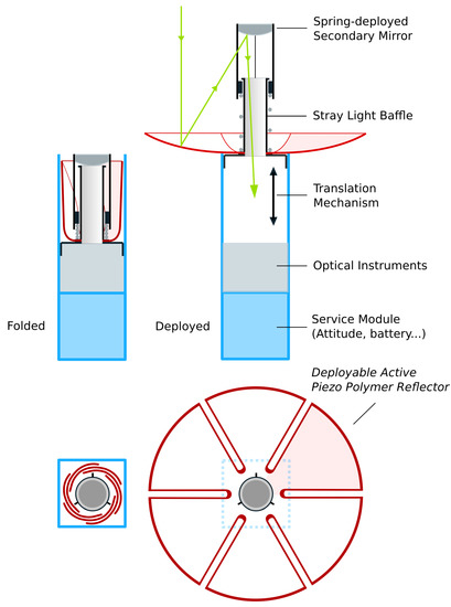
Figure 1.
Deployable reflector made of 6 petals folded in a 3U cubesat (left) and deployed (right) thanks to a translation mechanism.
It is clear that, if the image quality in the deployed configuration can be achieved at a reasonable cost, the significant increase of the light collecting area will tremendously improve the system performance.
1.3. Organization of the Paper
This paper is organized as follows: Section 2 summarizes earlier results on thin film PVDF-TrFE used as strain actuator material; a simple uniaxial material model was found consistent with experimental results and all the material parameters have been determined. Section 3 summarizes experimental results obtained with a small demonstrator controlled with 25 independent electrodes. Section 4 addresses the thermal sensitivity of the earlier (unimorph) design and considers options for improving the thermal stability: addition of a layer thermally balancing the PVDF-TrFE layer, and using a low CTE substrate (Figure 2b). These design changes are analyzed numerically on a reflector of 1 m controlled with an array of 120 independent electrodes. Section 5 considers the case of a petal reflector: numerical simulations show that the unimorph design is even more sensitive than the full reflector, but the balanced design has very good performance with a very small control budget.
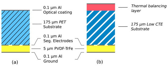
Figure 2.
Layer configurations: (a) unimorph configuration used in earlier studies; (b) with a thermal balancing layer and low CTE substrate.
2. Electrostrictive PVDF-TrFE Film
The behavior of the electrostrictive polymer was investigated in an earlier phase of the project [17], in the configuration described in Figure 2a. The active material consists of PVDF-TrFE (PVDF-TRFE FC25 from Piezotech, 0.12 g/mL in Acetone:Dimethylacetamide 95:5), annealed at 140 °C for 2 h. The material was applied by spin coating in [6] and by spray coating in [7] (spray coating can be easily scaled up to large sizes).
The behavior of the thin film of PVDF-TrFE can be modeled by a linear dielectric model:
and the quadratic unidirectional material model of the strain along the polarization direction:
where is the electric displacement, is the spontaneous polarization, is the dielectric constant ( F/m) and the electric field. is the electrostrictive coefficient, is the poling strain which takes place during the polarization. and are material properties that are determined experimentally. The isotropic in-plane strain (normal to the poling direction) is related to by the Poisson’s ratio
It follows that the piezoelectric coefficient is given by
Thus, after polarization, the PVDF-TrFE behavior is essentially piezoelectric, with a piezoelectric constant increasing slightly with the bias electric field (Figure 3). This equation confirms that an electrostrictive material can be made piezoelectric by applying a bias electric field [18]. The method for determining the material properties () has been described in [6,7]; they are reported in Table 1; the two values for refer to two independent methods of estimation. Notice that the value of the dielectric constant has been found consistently smaller for the spray-coated samples than for the spin coated ones.
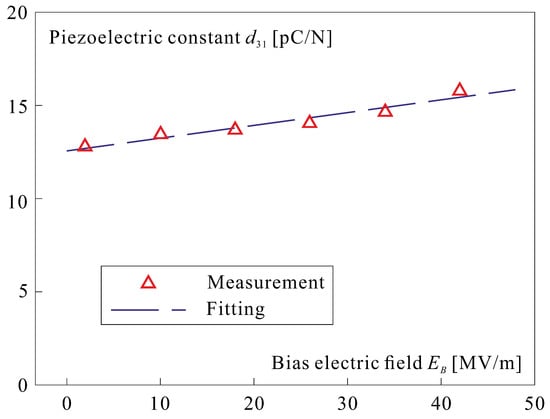
Figure 3.
Piezoelectric coefficient as a function of the bias electric field.

Table 1.
Estimation of material parameters of PVDF-TrFE.
According to Equation (5), the poling strain is given by
This was confirmed by direct measurement of the curvature during the poling process of a thin glass plate covered with PVDF-TrFE. The details of the experiment leading to Figure 3 can be found in [6].
3. Control of a Spherical Shell
So far, our work has been focused on the shape control with piezoelectric unimorph strain actuators of a thin spherical shell, ignoring its thermal response. The demonstrators consist of a PET substrate covered with a thin layer of PVDF-TrFE with Aluminum electrodes (Figure 2a); the material properties are listed in Table 2 (notice the large value of the CTE of the PVDF-TrFE). The sphere has a radius of 2.5 m; two mirrors have been built, one with a diameter of 100 mm, provided with a set of 7 independent electrodes, and one of 200 mm with 25 electrodes arranged in a keystone layout (Figure 4). The demonstrators were manufactured by MateriaNova according to the procedure described in [7]. The experimental determination of the influence functions of the electrodes is described in [6]. For illustration purpose, Figure 5 compares the cross sections of the measured influence functions of 6 electrodes of the same row (rotated successively by ) with a numerical simulation. More comprehensive results and details on the experimental setup are provided in [7].

Table 2.
Material properties.
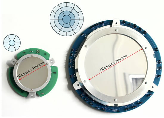
Figure 4.
Demonstrators built and tested in the earlier part of the project: D = 100 mm with 7 independent electrodes [6] and D = 200 mm with 25 independent electrodes [7].
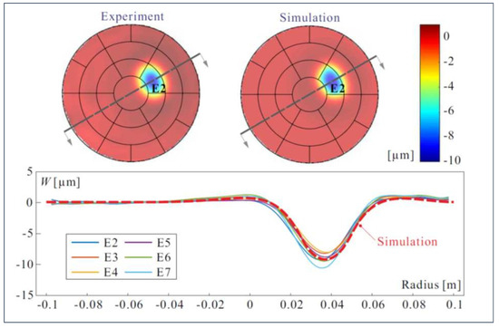
Figure 5.
Comparison between experimental cross sections of the influence functions of the six electrodes of the same row and a numerical simulation. The voltage applied is 100 V.
4. Thermal Response
The unimorph design with the layer configuration shown in Figure 2a and the CTE properties of the last line of Table 2 is extremely sensitive to even small temperature changes, whether it be uniform or a gradient. In this section, we examine numerically how the thermal deformations can be reduced in such a way that they can be controlled actively with the piezoelectric layer with only a small share of the control budget (i.e., a set of voltages much smaller than the maximum allowed, ).
Firstly, the design can be thermally balanced by adding a layer symmetrical to the PVDF-TrFE (Figure 2b) with equal value of
where is the biaxial Young modulus and t is the layer thickness (note that the thermal balancing layer, being on the front side, would also have to satisfy the surface roughness requirements).
Secondly, the thermal expansion of the substrate can be reduced, and even canceled, by using a zero-CTE polyimide such as the Novastrat-905 [19], available as a film sheet or liquid resin for spray and flow casting.
In order to investigate how the foregoing design changes affect the control, we consider a spherical reflector of 1 m diameter with a radius of curvature of 4 m; the reflector is fixed along the local axes y and z of a central hole of 0.2 m (Figure 6a). The layer distribution is that of Figure 7a for the unimorph case and Figure 7b for the balanced design. The balanced design assumes a passive layer of PVDF-TrFE on the inner (optical) side of the reflector, although other options are possible, provided that Equation (8) is satisfied. The material properties of Table 2 are assumed in the numerical calculations [20], except for the case with a substrate of low CTE for which a near zero value of K is assumed. A linear temperature gradient going from K on one side of the reflector to K on the opposite side is assumed.
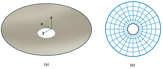
Figure 6.
(a) Spherical reflector with 1 m, m, 4 m, supported along the local axes y and z along the inner boundary. (b) Layout of the 120 control electrodes.
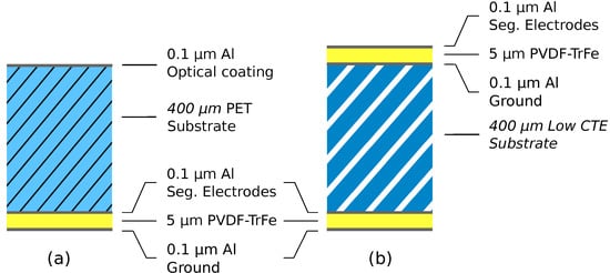
Figure 7.
Layer distribution used in the numerical simulation (a) unimorph design; (b) balanced design.
A set of 120 control electrodes is assumed (Figure 6b); the voltage distribution which minimizes the RMS residual surface figure error of the reflector is computed by inverting the Jacobian between the 120 control voltages and the reflector surface displacements on a regular grid of 200 × 200 points (with 31,000 points internal to the reflector shape); a simple Moore–Penrose pseudo-inverse is used in this case [7].
Columns 2 and 3 of Table 3 give, respectively, the peak to valley (PV) and the root mean squares (RMS) values of the surface figure error due to the thermal gradient of , respectively, for (i) the unimorph design, (ii) the balanced design with a substrate of large CTE, and (iii) the balanced design with a substrate with a near zero CTE. Columns 4 to 5 give the PV and the RMS residual errors when the control has been applied, and column 6 gives the range of the voltage applied to the various electrodes, (measure of the control budget). One sees that the addition of the thermal balancing layer and the near-zero CTE substrate reduce tremendously the residual error and the control budget.

Table 3.
Surface figure error due to a linear thermal gradient of K, before and after control with an array of 120 electrodes. All amplitudes are in m and voltages in V.
Figure 8 illustrates the case of the balanced layer design with near zero CTE substrate (last line in Table 3). Figure 8a shows the displacements along the z axis induced by the thermal gradient while Figure 8b shows the residual error when the control has been applied. Figure 8c shows the thermal displacements (in blue) and the residual error (in red) along the 30 cross section indicated on Figure 8a,b. Figure 8d shows the map of the correcting control voltages. The thermal displacement, residual error and voltage maps are similar to those of Figure 8 for both the unimorph and the thermally balanced high CTE design, except for the amplitudes, which are given in Table 3.
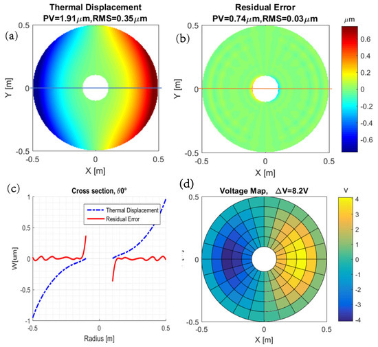
Figure 8.
Effect of a thermal gradient of K on the full reflector with balanced layer design and near zero CTE substrate (a) Thermal displacements along z without control. (b) Residual displacements after control. (c) Cross section at 30 of the displacements before (blue) and after control (red). (d) Map of the correcting voltages.
5. Petal Reflector
The petal configuration suggested in Figure 1 allows a simple deployment scenario, and also reduces the excessive hoop stiffness of the full spherical shell, simplifying the control of some optical aberrations, as investigated in [9]. In this section, we consider the same spherical shell as in the previous section, except that it is formed of six petals as shown in Figure 9. It is also controlled with a set of 120 electrodes. To give an idea of the authority of the piezoelectric actuation, the application of 100 V to all the 20 electrodes of one petal produces a tip displacement of 250 m.
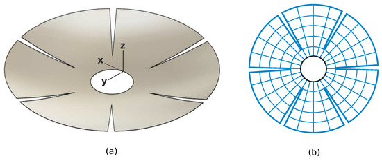
Figure 9.
(a) Geometry of the petal reflector (the boundary conditions are the same as in Figure 6). (b) Layout of the 120 electrodes.
Table 4 shows the surface figure error induced by the same linear thermal gradient of K, before and after control with the 120 piezoelectric actuators, for the same three layer configurations considered in Table 3. One sees that, in absence of control, the distortion of the unimorph reflector is significantly larger than with the full reflector, while the residual surface figure error after control of the balanced configurations are even smaller than those of the full reflector and obtained with a smaller actuator budget.

Table 4.
Surface figure error of the petal reflector due to a thermal gradient of K, before and after control with an array of 120 electrodes. All amplitudes are in m and voltages in V.
Figure 10 illustrates the case of the balanced layer design with near zero CTE substrate (last line in Table 4). Figure 10a shows the displacements along the z axis induced by the thermal gradient while Figure 10b shows the residual error when the control has been applied. Figure 10c shows the thermal displacements (in blue) and the residual error (in red) along the 30 cross section indicated on Figure 10a,b. Figure 10d shows the map of the correcting control voltages. The thermal displacement, residual error and voltage maps are similar to those of Figure 10 for both the unimorph and the thermally balanced high CTE design, except for the amplitudes which are given in Table 4.
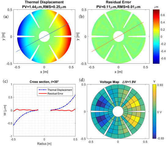
Figure 10.
Effect of a thermal gradient of K on the petal reflector with balanced layer design and near zero CTE substrate. (a) Thermal displacements along z without control. (b) Residual displacements after control. (c) Cross section at 30 of the displacements before (blue) and after control (red). (d) Map of the correcting voltages.
6. Conclusions
The first part of this paper summarizes earlier studies on PVDF-TrFE for controlling the shape of thin polymer shell reflectors. With proper annealing conditions, a piezoelectric coefficient close to pC/N has been achieved. The electrode size to achieve an accurate surface figure correction is critically related to the thickness and the curvature of the shell.
The second part of this paper is focused on the thermal response to a temperature gradient. It is shown numerically that, due to the very high CTE of the PVDF-TrFE, the unimorph configuration provides a poor design, very sensitive to thermal gradients; the thermal deformations are difficult to control with the array of piezoelectric actuators and they require large control voltages. This drawback can be alleviated by adding a passive layer of material to balance the thermal behavior of the shell (with sufficiently low surface roughness). The behavior can be further improved by using a low-CTE substrate.
Finally, the paper examines the case of a petal reflector; the unimorph layer configuration is even more sensitive than the full reflector, but the behavior of the thermally balanced design turns out to be better than that of the full reflector. The petal reflector with thermal balancing layer and low CTE substrate results in a 160-fold reduction in residual error, and 500-fold reduction in control voltage as compared to the baseline design.
Author Contributions
Conceptualization, A.P., C.J.G.N., and K.W.; software, C.J.G.N., K.W. and D.T.; validation, C.J.G.N. and D.T.; writing—original draft preparation, A.P.; writing—review and editing, C.J.G.N.; visualization, C.J.G.N.; supervision, A.P.; All authors have read and agreed to the published version of the manuscript.
Funding
Part of this research has been supported by ESA-ESTEC in the framework of the GSTP program, project Multilayer Adaptive Thin Shell Reflectors for Future Space Telescopes (MATS). RFQ 3-14210/14/PA/NL.
Institutional Review Board Statement
Not applicable.
Informed Consent Statement
Not applicable.
Data Availability Statement
Not applicable.
Acknowledgments
The authors wish to thank G. Rodrigues and D. Alaluf from ESA-ESTEC for their contributions to the earlier stages of this project. The demonstrators were manufactured by D. Robert and Th. Godefroid from MateriaNova (Mons, Belgium) within the MATS project.
Conflicts of Interest
The authors declare no conflict of interest.
Abbreviations
The following abbreviations are used in this manuscript:
| AO | Adaptive Optics |
| LIDAR | Light Detection and Ranging |
| PET | Polyethylene terephthalate |
| PVDF-TrFE | poly(vinylidene fluoride-co-trifluoroethylene) |
| RMS | Root Mean Square |
References
- Villalba, V.; Kuiper, H.; Gill, E. Review on thermal and mechanical challenges in the development of deployable space optics. SPIE J. Astron. Telesc. Instrum. Syst. 2020, 6, 10902-1. [Google Scholar] [CrossRef]
- Jenkins, C.H. Gossamer Spacecraft: Membrane and Inflatable Structures Technology for Space Applications; American Institute of Aeronautics and Astronautics: Reston, VA, USA, 2001. [Google Scholar]
- Flint, E.; Lindler, J.; Hall, J.; Rankine, C.; Regelbrugge, M. Overview of form stiffened thin film shell characteristic behavior. In Proceedings of the 47th AIAA/ASME/ASCE/AHS/ASC Structures, Structural Dynamics and Materials Conference, Newport, RI, USA, 1–4 May 2006; p. 1900. [Google Scholar]
- Flint, E.; Bales, G.; Glaese, R.; Bradford, R. Experimentally characterizing the dynamics of 0.5 m diameter doubly curved shells made from thin films. In Proceedings of the 44th AIAA/ASME/ASCE/AHS/ASC Structures, Structural Dynamics and Materials Conference, Norfolk, VA, USA, 7–10 April 2003; p. 1831. [Google Scholar]
- Chodimella, S.; Moore, J.; Otto, J.; Fang, H. Design Evaluation of a Large Aperture Deployable Antenna. In Proceedings of the AIAA/ASME/ASCE/AHS/ASC Structures, Structural Dynamics and Materials Conference, Newport, RI, USA, 1–4 May 2006. [Google Scholar]
- Wang, K.; Godfroid, T.; Robert, D.; Preumont, A. Electrostrictive PVDF-TrFE thin film actuators for the control of adaptive thin shell reflectors. Actuators 2020, 9, 53. [Google Scholar] [CrossRef]
- Wang, K.; Godfroid, T.; Robert, D.; Preumont, A. Adaptive shell spherical reflector actuated with PVDF-TrFE thin film strain actuators. Actuators 2021, 10, 7. [Google Scholar] [CrossRef]
- Alaluf, D.; Wang, K.; Preumont, A. Thermal Balance and Active Damping of a Piezoelectric Deformable Mirror or Adaptive Optics. Actuators 2019, 8, 75. [Google Scholar] [CrossRef]
- Preumont, A.; Alaluf, D.; Wang, K.; Rodrigues, G. Adaptive thin shell reflectors for future space telescopes. In Proceedings of the 14th European Conference on Spacecraft Structures, Materials and Environmental Testing (ECSSMET), Toulouse, France, 27–30 September 2016. [Google Scholar]
- Wang, K. Piezoelectric Adaptive Mirrors for Ground-Based and Space Telescopes. Ph.D. Thesis, Active Structures Laboratory, Université Libre de Bruxelles, Brussels, Belgium, 2019. [Google Scholar]
- Jin, H.; Lim, J.; Kim, Y.; Kim, S. Optical Design of a Reflecting Telescope for CubeSat. J. Opt. Soc. Korea 2013, 17, 533–537. [Google Scholar] [CrossRef][Green Version]
- Guelman, M.; Kogan, A.; Kazarian, A.; Livne, A.; Orenstein, M.; Michalik, H.; Arnon, S. Acquisition and pointing control for inter-satellite laser communications. IEEE Trans. Aerosp. Electron. Syst. 2004, 40, 1239–1248. [Google Scholar] [CrossRef]
- Peral, E.; Imken, T.; Sauder, J.; Statham, S.; Tanelli, S.; Price, D.; Chahat, N.; Williams, A. Raincube, a Ka-band Precipitation Radar in a 6U CubeSat. In Proceedings of the 31st Annual AIAA/USU Conference on Small Satellites, Noordwijk, The Netherlands, 12–14 September 2017. [Google Scholar]
- Champagne, J.; Hansen, S.; Newswander, T.; Crowther, B. CubeSat image resolution capabilities with deployable optics and current imaging technology. In Proceedings of the 28th Annual AIAA/USU Conference Small Satellites, Logan, UT, USA, 4–7 August 2014. [Google Scholar]
- Schwartz, N.; Pearson, D.; Todd, S.; Vick, A.; Lunney, D.; MacLeod, D. A segmented deployable primary mirror for earth observation from a CubeSat platform. In Proceedings of the 29th AIAA/USU Conference Small Satell, Logan, UT, USA, 8–13 August 2015. [Google Scholar]
- Boone, B.G.; Bruzzi, J.R.; Kluga, B.E.; Millard, W.P.; Fielhauer, K.B.; Duncan, D.D.; Hahn, D.V.; Drabenstadt, C.W.; Maurer, D.E.; Bokulic, R.S. Optical Communications Development for Spacecraft Applications. Johns Hopkins APL Tech. Dig. 2004, 25, 306–315. [Google Scholar]
- ESA-GSTP-4, Multilayer Adaptive Thin Shell Reflectors for Future Space Telescopes (MATS), RFQ3-14210/14/PA/NL. 2020.
- Li, F.; Jin, L.; Xu, Z.; Zhang, S. Electrostrictive effect in ferroelectrics: An alternative approach to improve piezoelectricity. Appl. Phys. Rev. 2014, 1, 011103. [Google Scholar] [CrossRef]
- Poe, G.D.; Patrick, B.G. Zero CTE polyimides for athermal optical membranes. Proc. SPIE 2008, 7061, 706114. [Google Scholar] [CrossRef]
- Piefort, V.; Loix, N.; Preumont, A. Modeling of piezolaminated composite shells for vibration control. In Proceedings of the ESA Conference on Spacecraft Structures, Materials and Mechanical Testing, Braunschweig, Germany, 4–6 November 1998. [Google Scholar]
Publisher’s Note: MDPI stays neutral with regard to jurisdictional claims in published maps and institutional affiliations. |
© 2022 by the authors. Licensee MDPI, Basel, Switzerland. This article is an open access article distributed under the terms and conditions of the Creative Commons Attribution (CC BY) license (https://creativecommons.org/licenses/by/4.0/).