
Analysis, Design, and Optimization of a Novel Asymmetrical Bistable Short Mover Permanent Magnet Actuator for High-Voltage Circuit Breaker Application


Abstract
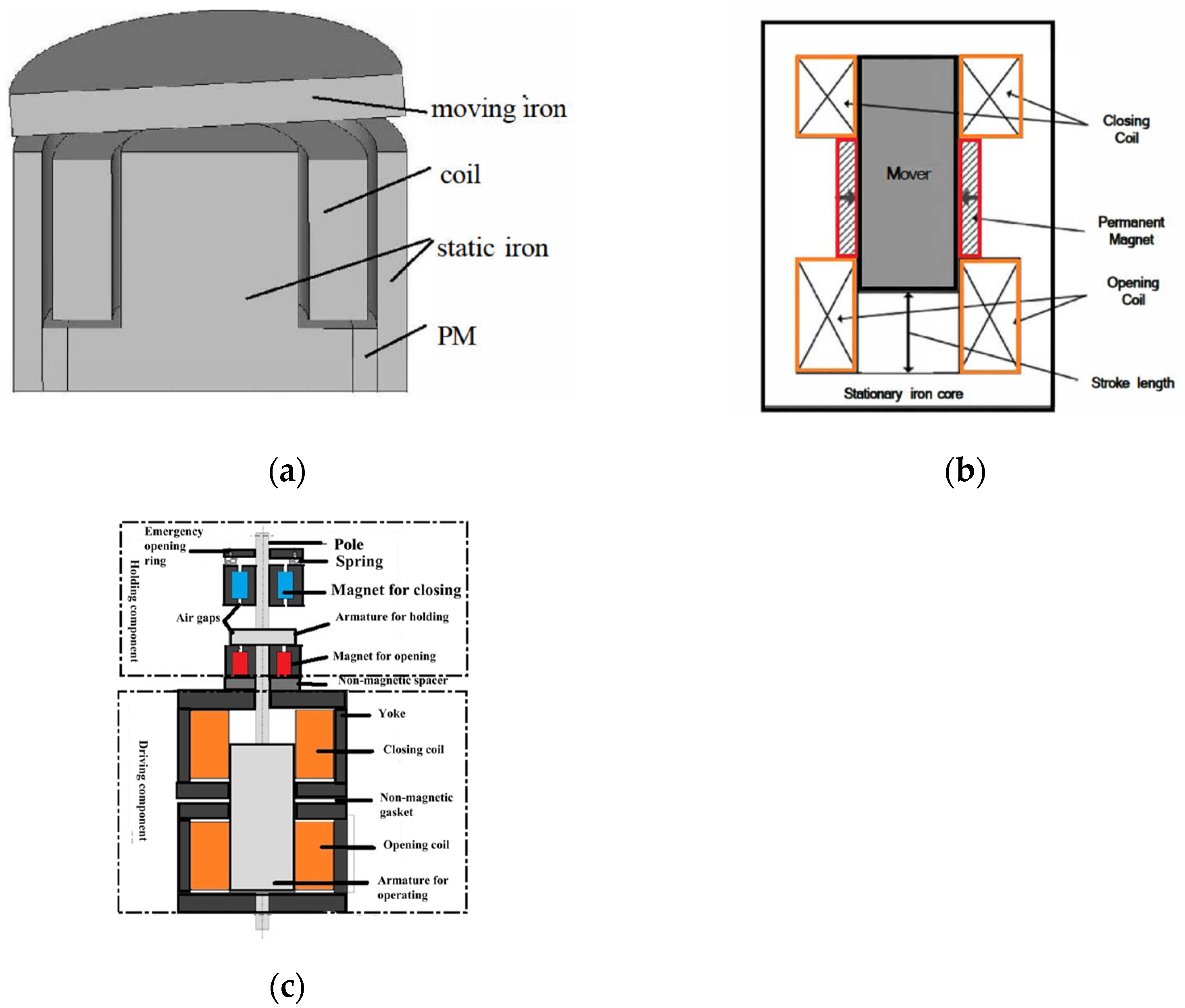
:1. Introduction
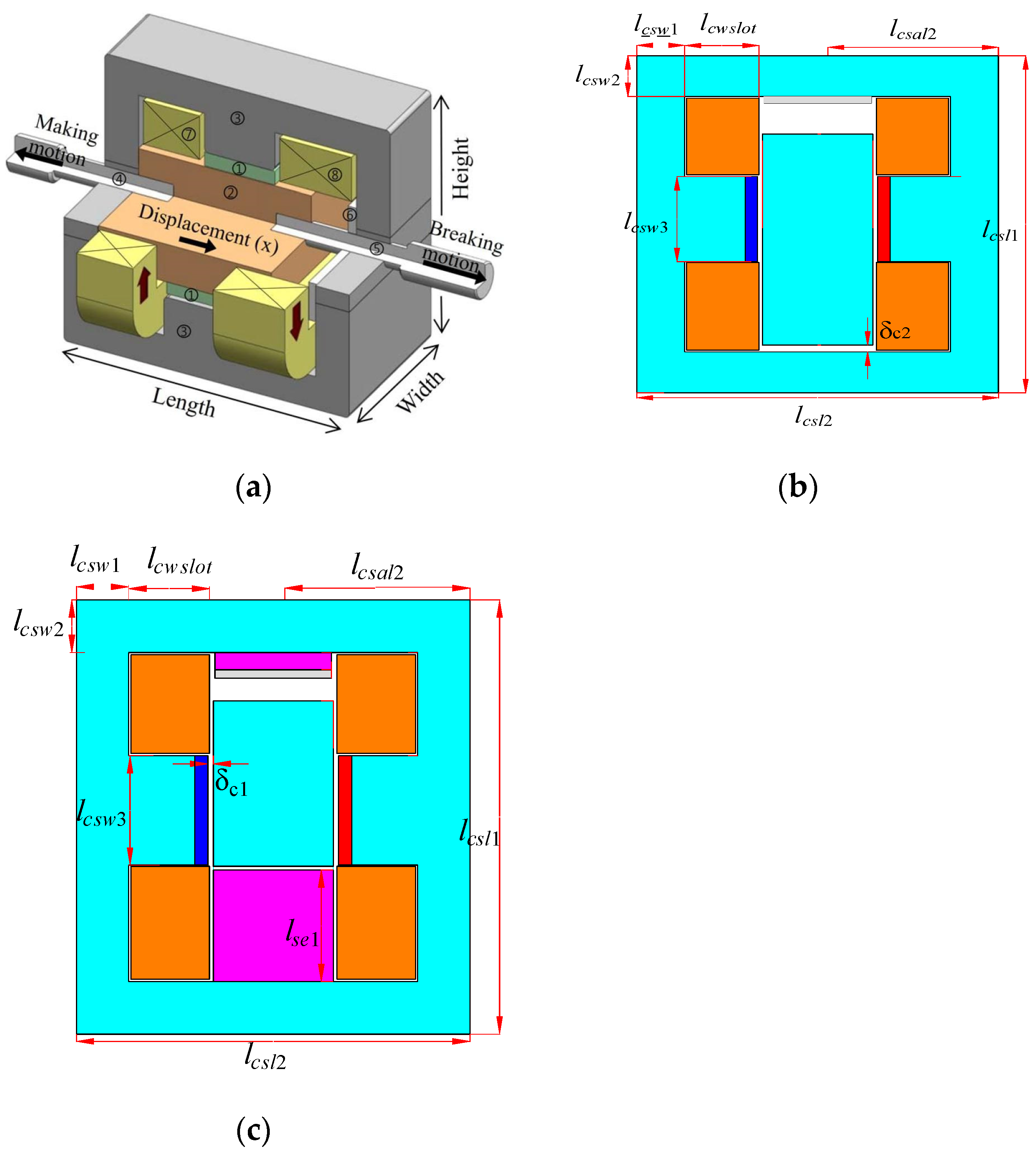
2. Novel Structure of ABSMPMA
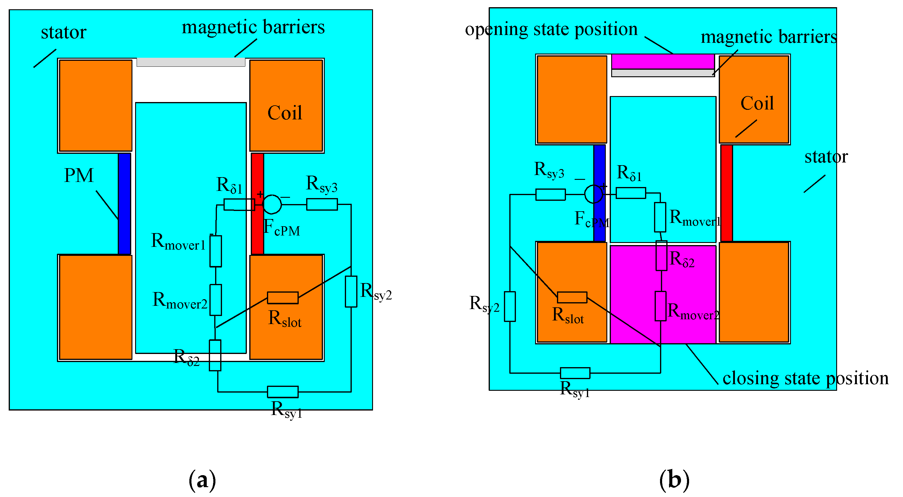
3. Working Principle of ABSMPMA
- The leakage flux of the end is negligible;
- The magnetic circuit in the stator and mover are not saturated.
4. Numerical Analysis and Simulation Results
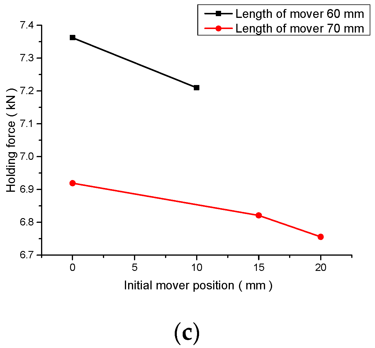
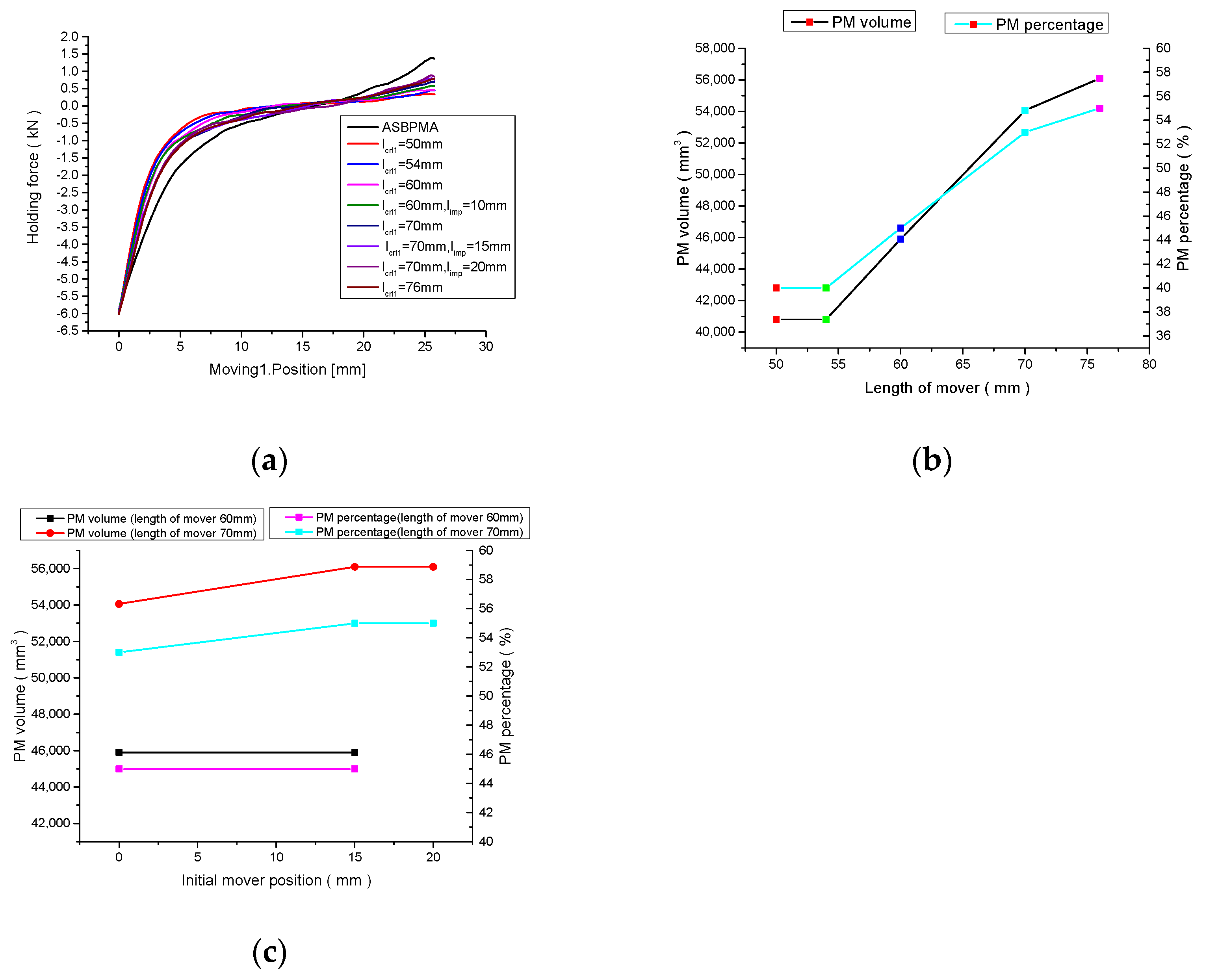
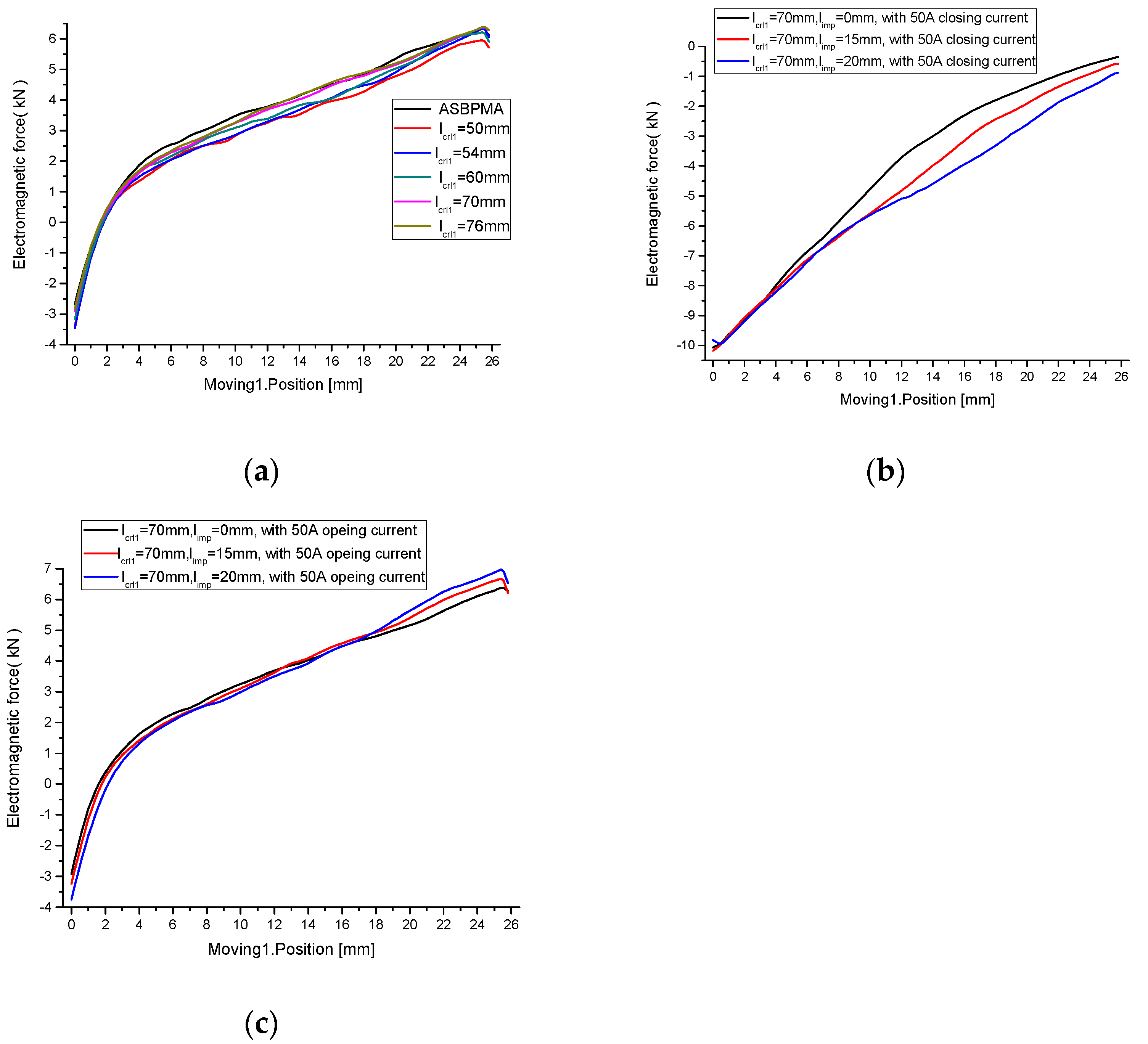
4.1. The Static Characteristics
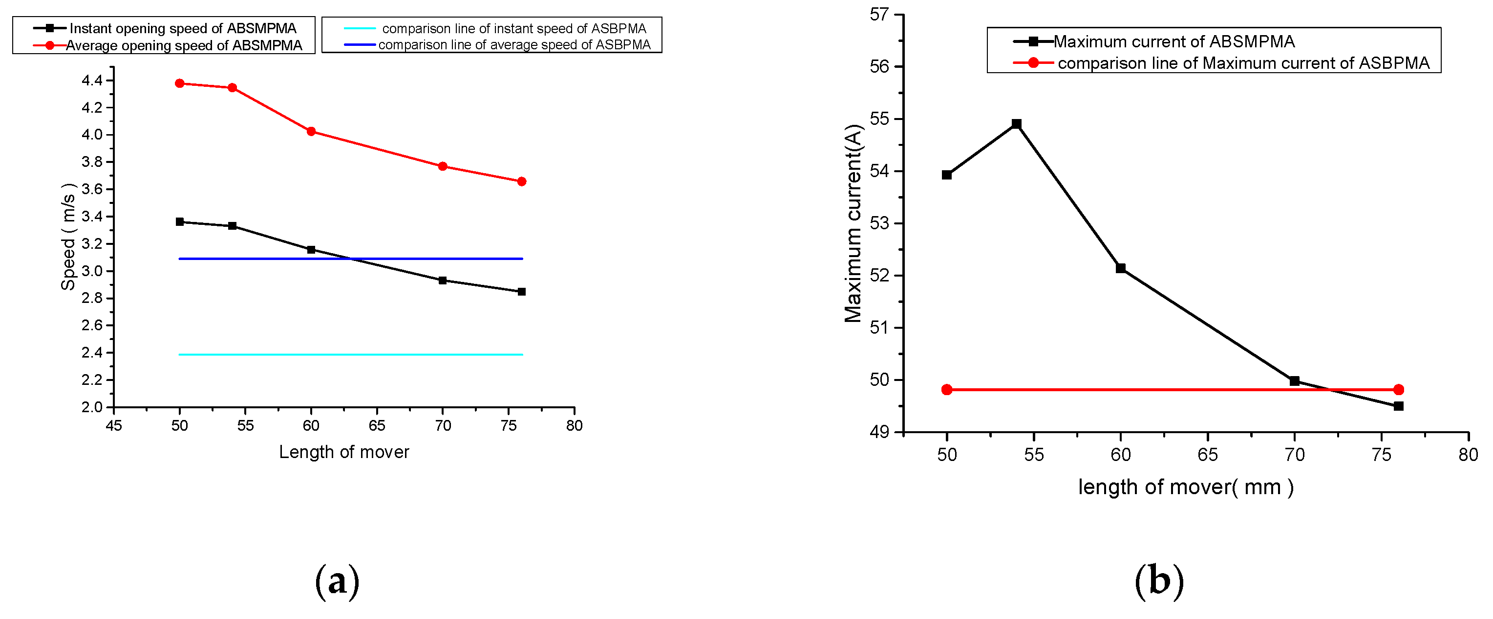
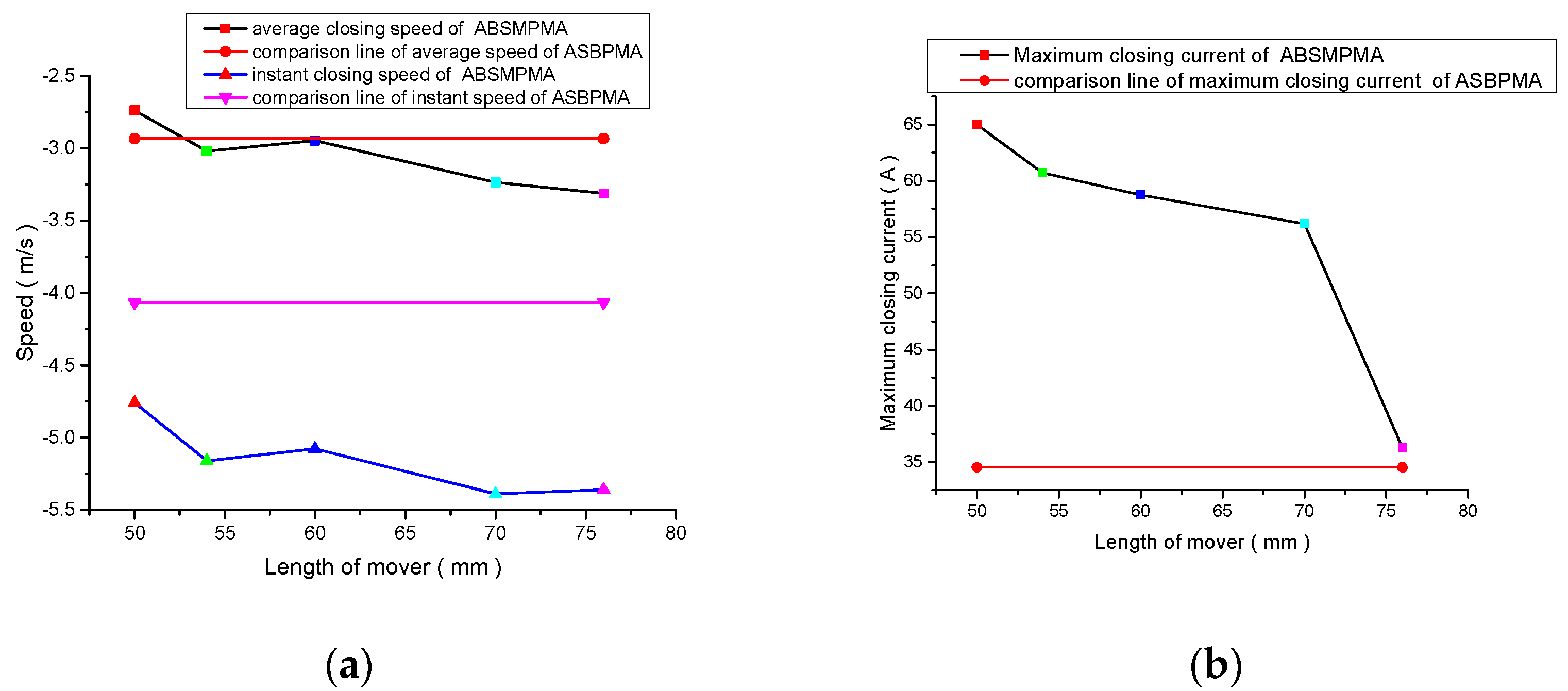
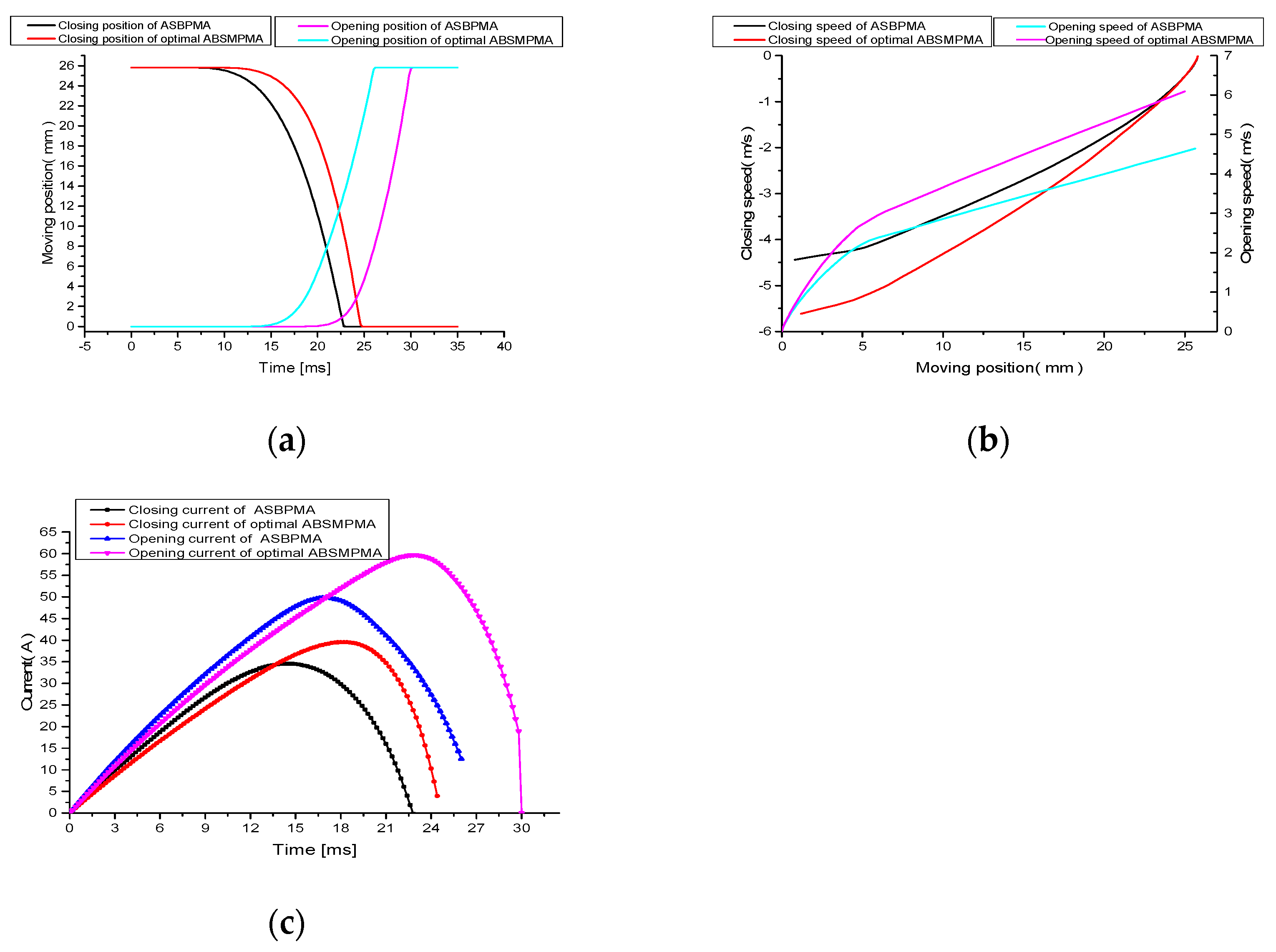
4.2. The Dynamic Characteristic
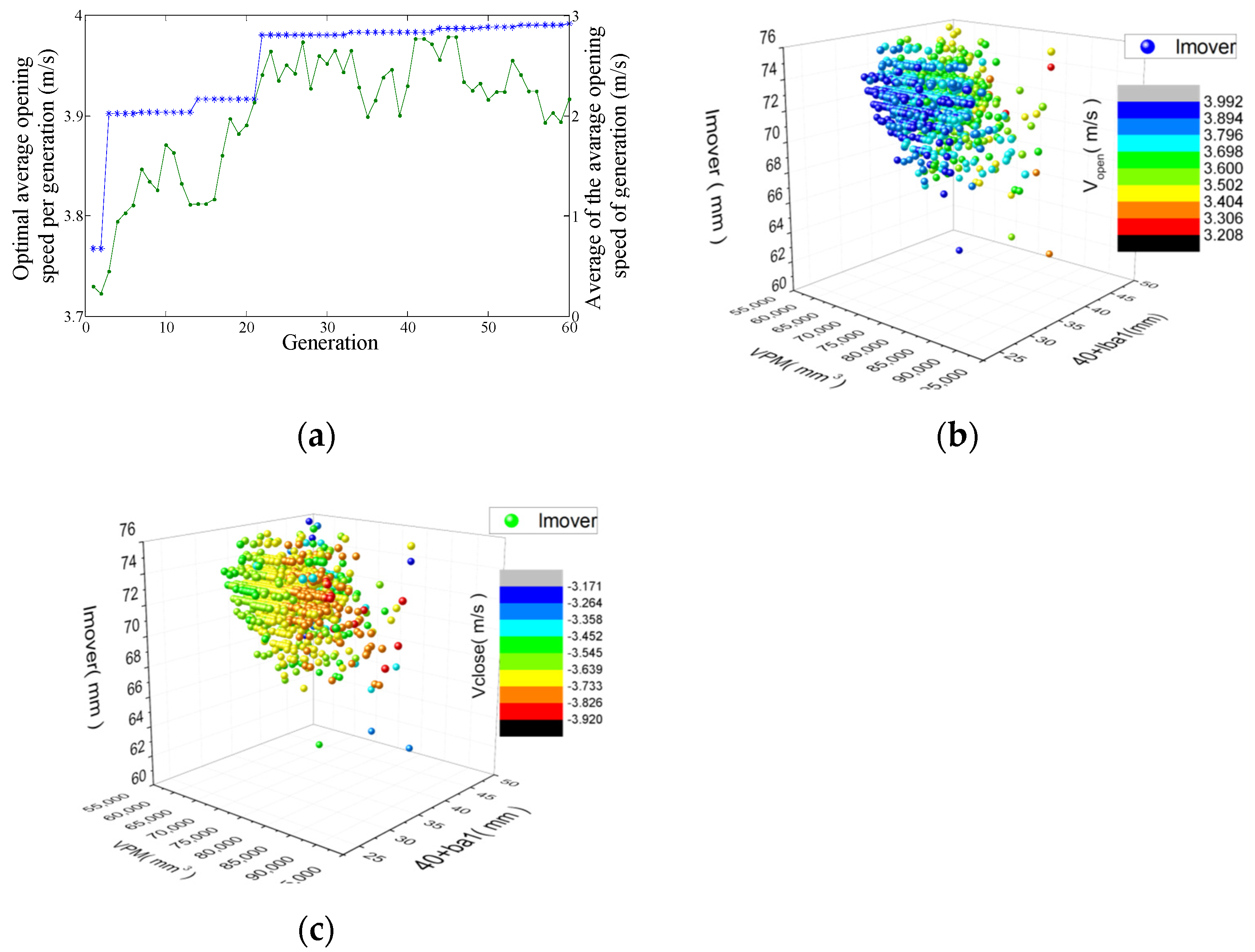
5. Optimization by Genetic Algorithm
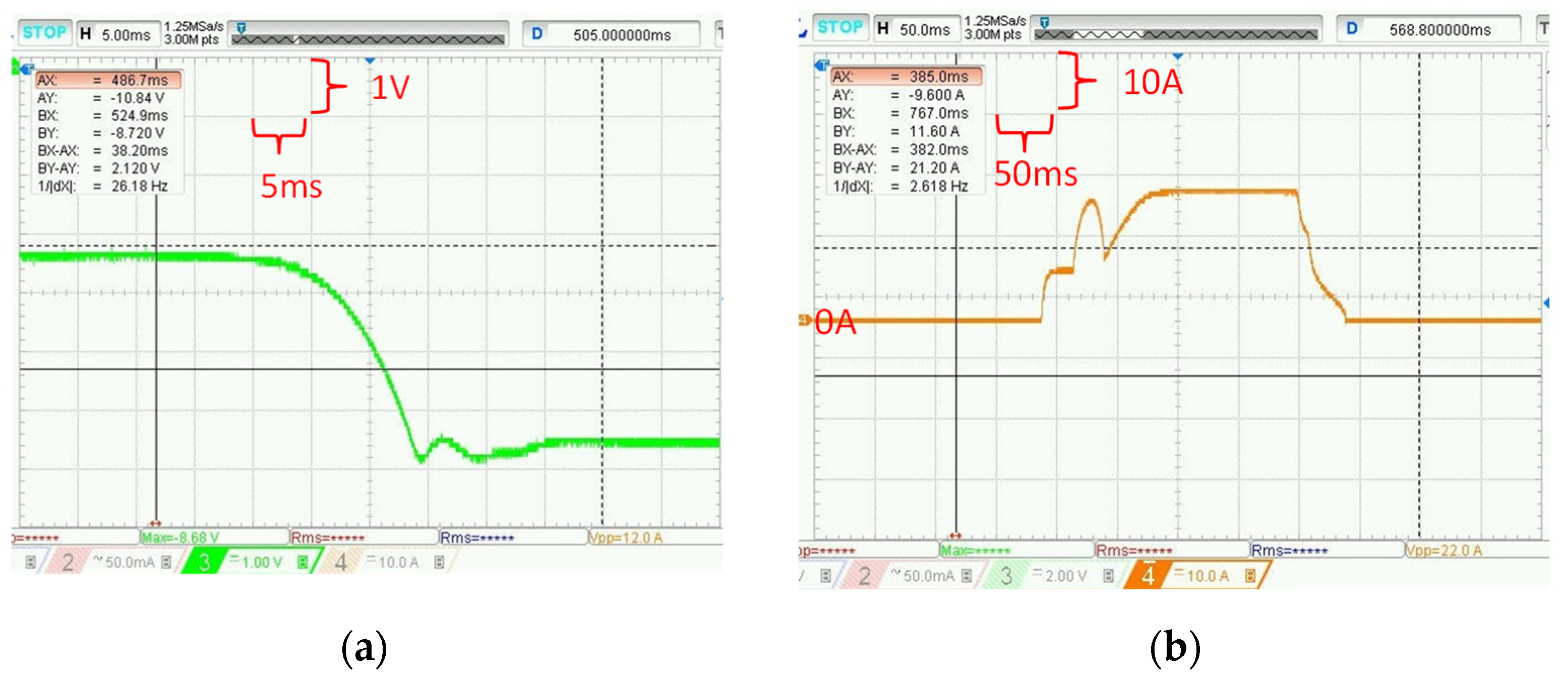
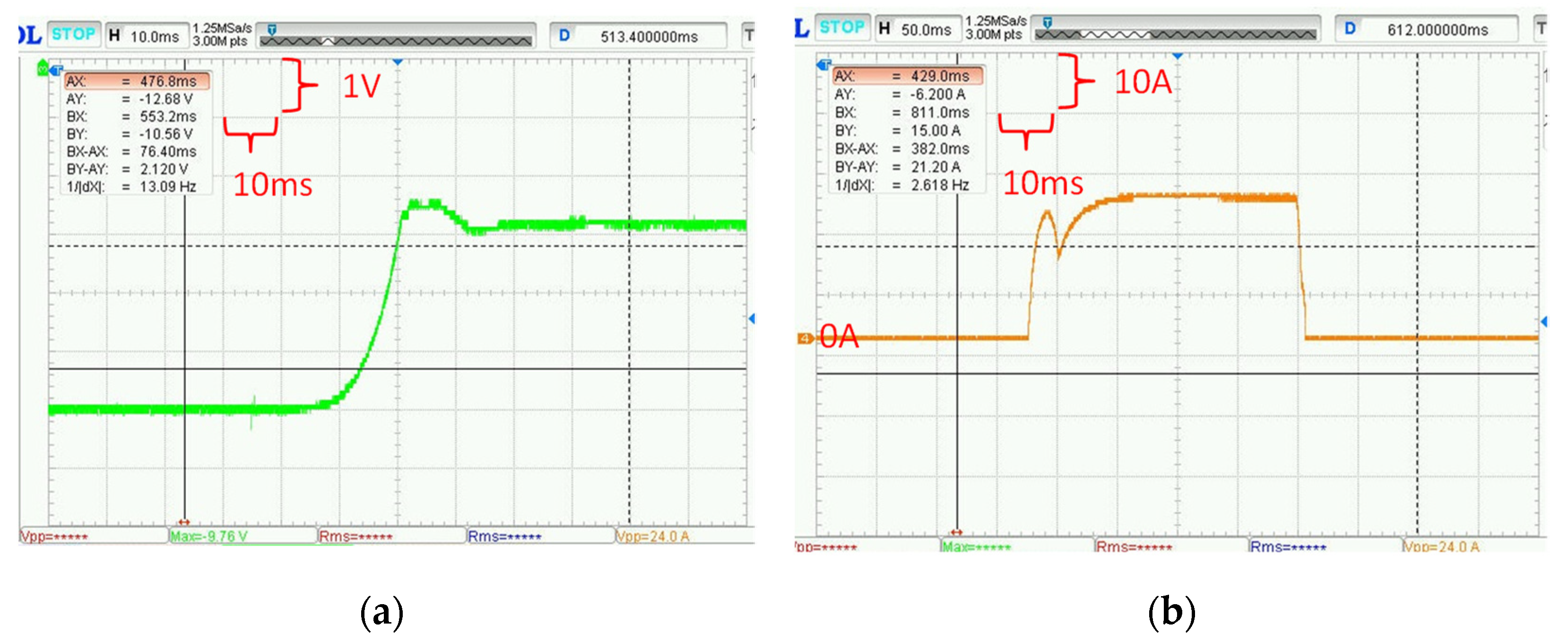
6. Experimental Results
7. Conclusions and Discussion
- The ABSMPMA has a small mover, which is shorter than the width of the tooth plus the stroke. Hence, the mover mass is lesser than that of the ASBPMA, which improves the opening and closing dynamic characteristics of the HVCB with the ABSMPMA;
- The retaining force of the ASBPMA is smaller than the ABSMPMA with the same sizes of permanent magnet;
- The ABSMPMA, with same retaining force, needs approximately half the magnet volumes of the ASBPMA, which is the key to decreasing cost;
- The technology of adjusting the initial mover position can be used to balance maximum closing current and maximum opening current as well as the opening and closing dynamic characteristics.
Author Contributions
Funding
Institutional Review Board Statement
Informed Consent Statement
Data Availability Statement
Acknowledgments
Conflicts of Interest
References
- Wan, S.; Dou, L.; Li, C.; Wu, P.; Liu, R. Study on on-line detection of characteristic parameters in high voltage circuit breaker opening process based on vibration signal. Electr. Power Compon. Syst. 2018, 46, 1969–1978. [Google Scholar] [CrossRef]
- Tseng, K.H.; Shiao, Y.F.; Cheng, P.Y.; Xu, Z.Z. Analysis and improvement of modeling of electromagnetic actuator for medium voltage gas insulated switchgear. Electr. Power Compon. Syst. 2014, 42, 1576–1586. [Google Scholar] [CrossRef]
- Fu, H. Research on Characteristics of Permanent Magnet Operating Mechanism and Its Synchronous Control Technology. Ph.D. Thesis, Central South University, Changsha, China, 2005. [Google Scholar]
- Wang, K.D.; Yi, W.; Ming-Zhi, Z. Design of half bistable permanent magnetic actuator used in 12kV vacuum circuit breaker. Adv. Technol. Electr. Eng. Energy. 2017, 36, 29–36. [Google Scholar]
- Shu, L.; Wu, L.; Wu, G.; Wu, Z. A fully coupled framework of predicting the dynamic characteristics of permanent magnet contactor. IEEE Trans. Magn. 2016, 52, 1–7. [Google Scholar] [CrossRef]
- Bak, H.J.; Ro, J.S.; Chung, T.K.; Jung, H.K. Characteristics analysis and design of a novel magnetic contactor for a 220 V/85 A. IEEE Trans. Magn. 2013, 49, 5498–5506. [Google Scholar] [CrossRef]
- Lin, H.; Wang, X.; Fang, S.; Jin, P.; Ho, S.L. Design, optimization, and intelligent control of permanent-magnet contactor. IEEE Trans. Ind. Electr. 2013, 60, 5148–5159. [Google Scholar] [CrossRef]
- Lin, X.; Shi, K.J.; Xu, J.Y. Influence of permeable property of material on dynamic characteristic of permanent magnetic actuator. High Volt. Appar. 2013, 49, 1–8. [Google Scholar]
- Lim, S.; Jeong, S.; Min, S. Multi-component layout optimization method for the design of a permanent magnet actuator. IEEE Trans. Magn. 2016, 52, 1–4. [Google Scholar] [CrossRef]
- Noh, M.D.; Park, Y.W. Topology selection and design optimization for magnetostrictive inertial actuators. J. Appl. Phys. 2012, 111, 07E715-1–07E715-3. [Google Scholar] [CrossRef]
- Shi, X.; Chang, S. Commutation force ripple reduction in a novel linear brushless DC actuator based on predictive current control. Electr. Power Compon. Syst. 2011, 39, 1609–1620. [Google Scholar] [CrossRef]
- Hung, C.Y.; Chi, C.T. A contact de-bounce technique for an AC permanent magnet contactor. WSEAS Trans. Syst. 2010, 9, 476–487. [Google Scholar]
- Fang, S.; Lin, H.; Wang, X.; Jin, P. Design and performance analysis of a vacuum permanent magnet contactor. In Proceedings of the 2010 14th Biennial IEEE Conference on Electromagnetic Field Computation, Chicago, IL, USA, 9–12 May 2010; p. 1. [Google Scholar]
- Dullni, E. A vacuum circuit-breaker with permanent magnetic actuator for frequent operations. In Proceedings of the ISDEIV. 18th International Symposium on Discharges and Electrical Insulation in Vacuum (Cat. No.98CH36073), Eindhoven, The Netherlands, 17–21 August 1998; Volume 2, pp. 688–691. [Google Scholar]
- Chen, X.; Zhu, Z.Q. Analytical determination of optimal split ratio of E-Core permanent magnet linear oscillating actuators. IEEE Trans. Ind. Appl. 2011, 47, 25–33. [Google Scholar] [CrossRef]
- Ahn, H.M.; Chung, T.K.; Oh, Y.H.; Song, K.D.; Kim, Y.I.; Kho, H.R.; Hahn, S.C. Optimal design of permanent magnetic actuator for permanent magnet reduction and dynamic characteristic improvement using response surface methodology. J. Electr. Eng. Technol. 2015, 10, 935–943. [Google Scholar] [CrossRef] [Green Version]
- Hu, J.; Zhao, M.; Zou, J.; Li, Y. Comparative Study of Stator Configurations of a Permanent Magnet Linear Oscillating Actuator for Orbital Friction Vibration Actuator. Appl. Sci. 2017, 7, 630. [Google Scholar] [CrossRef] [Green Version]
- You, J.; Zhang, K.; Zhu, Z.; Liangm, H. Novel design and research for a high-retaining-force, bi-directional, electromagnetic valve actuator with double-layer permanent magnets. J. Magn. 2016, 21, 65–71. [Google Scholar] [CrossRef]
- Lee, C.; Shin, B.H.; Bang, Y. Designing a permanent-magnetic actuator for vacuum circuit breakers using the taguchi method and dynamic characteristic analysis. IEEE Trans. Ind. Electr. 2016, 63, 1655–1664. [Google Scholar] [CrossRef]
- Ahn, H.M.; Lee, J.D.; Lee, B.J.; Hahn, S.C. Optimal design of permanent magnet actuator for vacuum circuit breakers using response surface methodology. Int. J. Appl. Electromagn. Mech. 2014, 45, 503–509. [Google Scholar] [CrossRef]
- Immonen, P.; Ruuskanen, V.; Pyrhonen, J. Moving magnet linear actuator with self-holding functionality. IET Electr. Syst. Transp. 2018, 8, 182–187. [Google Scholar] [CrossRef]
- Abdalla, I.I.; Ibrahim, T.; Nor, N.B.M. Development and optimization of a moving-magnet tubular linear permanent magnet motor for use in a reciprocating compressor of household refrigerators, Int. J. Electr. Power Energy Syst. 2016, 77, 263–270. [Google Scholar] [CrossRef]
- Aslam, J.; Li, X.H.; Janjua, F.K. Design of a hybrid magnetomotive force electromechanical valve actuator. Front. Inf. Technol. Electron. Eng. 2017, 18, 1635–1643. [Google Scholar] [CrossRef]
- Yang, S.; Tsai, Y. Design of a thrust actuator for magnetic bearings with low radial attraction force. IEEE Trans. Magn. 2012, 48, 3587–3590. [Google Scholar] [CrossRef]
- Jeong, H.S. Novel torque motor model for performance design and analysis of a servo valve with permanent magnets. J. Mech. Sci. Technol. 2018, 32, 2253–2259. [Google Scholar] [CrossRef]
- Lee, J.; Lee, S.; Kim, K.; Lee, J. Multi-material topology optimization of magnetic actuator with segmented permanent magnets. IEEE Trans. Magn. 2018, 54, 1–6. [Google Scholar] [CrossRef]
- Bae, B.; Kim, M. Electromagnetic actuator with novel electric brake for circuit breaker. J. Magn. 2016, 21, 340–347. [Google Scholar] [CrossRef] [Green Version]
- Hong, S.K.; Ro, J.S.; Jung, H.K. Optimal design of a novel permanent magnetic actuator using evolutionary strategy algorithm and kriging meta-model. J. Electr. Eng. Technol. 2014, 9, 471–477. [Google Scholar] [CrossRef]
- Ro, J.S.; Hong, S.K.; Jung, H.K. Characteristic analysis and design of a novel permanent magnetic actuator for a vacuum circuit breaker. IET Electr. Power Appl. 2013, 7, 87–96. [Google Scholar] [CrossRef]
- Park, H.; Jung, H.; Ro, J. Analysis and design of diverse electromagnet type actuators for moulded case circuit breaker. IET Electr. Power Appl. 2016, 10, 849–857. [Google Scholar] [CrossRef]
- Bi, Y.H.; Dong, E.Y.; Yin, G.X.; Xu, J.Y.; Liu, M.W. Parameter design and dynamic characteristic analysis of magnetic force actuator based on Visual Basic interface programming. Appl. Mech. Mater. 2014, 492, 227–231. [Google Scholar] [CrossRef]
- Ro, J.; Bak, H.; Jung, H. Characteristic analysis and design of a novel lorentz force driving actuator for a molded case circuit breaker. IET Electr. Power Appl. 2015, 9, 1–9. [Google Scholar] [CrossRef]
- Jiang, J.; Lin, H.; Fang, S. Optimization design of a permanent magnet actuator for 126-kV vacuum circuit breaker. IEEE Trans. Appl. Supercond. 2018, 28, 1–5. [Google Scholar] [CrossRef]
- Zhang, M.; Wang, Y.; Li, P.; Wen, H. Comparative studies on two electromagnetic repulsion mechanisms for high-speed vacuum switch. IET Electr. Power Appl. 2018, 12, 247–253. [Google Scholar] [CrossRef]
- Qin, T.; Dong, E.; Wang, Y.; Zou, J. Influence of the contact opening speed on DC vacuum arc. IEEE Trans. Plasma Sci. 2015, 43, 878–883. [Google Scholar]
- Xu, Z.; Fang, S.; Lin, H.; Liu, K.; Kong, Q.; Wu, G.; Chen, Y.; Liu, Q. Analysis of a Permanent Magnetic Actuator with Three Coils for High Voltage Vacuum Circuit Breaker. High Volt Appar. 2016, 52, 111–117. [Google Scholar]
- Wang, Z.; Sun, L.; He, S.; Geng, Y.; Liu, Z. A permanent magnetic actuator for 126 kV vacuum circuit breakers. IEEE Trans. Magn. 2014, 50, 129–135. [Google Scholar] [CrossRef]
- Fang, S.; Xia, M.; Lin, H.; Ho, S. Analysis and design of a high-speed permanent magnet characteristic actuator using eddy current effect for high-voltage vacuum circuit breaker. IET Electr. Power Appl. 2016, 10, 268–275. [Google Scholar] [CrossRef]
- Fang, S.; Liu, Q.; Lin, H.; Ho, S.L. A novel flux-weakening control strategy for permanent-magnet actuator of vacuum circuit breaker. IEEE Trans. Ind. Electron. 2016, 63, 2275–2283. [Google Scholar] [CrossRef]
- Zeng, G.; Xiangyu, Y.; Yin, H.; Jing, Y.; Zhao, S.; Cao, J. Unsymmetrical bistable multimagnetic circuit permanent magnet actuator for high-voltage circuit breaker application: Analysis, design, and dynamic simulation. IET Electr. Power Appl. 2020, 14, 827–836. [Google Scholar] [CrossRef]
- Dai, K.; Zhu, Z.; Jin, H.; Ma, X.; Duan, W.; Wang, J.; Zhang, W. Bionic soft multimodal actuators for fast, large deformation under ultralow magnetic conditions. Adv. Mater. Interfaces 2022, 9, 2200351. [Google Scholar] [CrossRef]
- Zuo, Q.; Hu, S.; Zuo, C. Structural design and performance calculation for flip-flop permanently magnetic operating mechanism(I). Hua Tong Technol. 2002, 2, 13–17. [Google Scholar]
- Tang, Y. Electro Mechanics Fourth Edition; China Machine Press: Beijing, China, 2013. [Google Scholar]
- Tang, R. Modern Permanent Magnet Machines Theory and Design; China Machine Press: Beijing, China, 2015. [Google Scholar]
- Semero, Y.K.; Zhang, J.; Zheng, D.; Wei, D. An accurate very short-term electric load forecasting model with binary genetic algorithm based feature selection for microgrid applications. Electr. Power Compon. Syst. 2018, 46, 1570–1579. [Google Scholar] [CrossRef]
- LI, H.; XU, L.; LI, J. Optimizing circuit breaker temperature control technique based on GA toolbox of Matlab. Comput. Sci. 2017, 44, 557–560. [Google Scholar]


| Item | Value |
|---|---|
| Stroke (mm) | 20 |
| Overrun (mm) | 6 |
| Holding force in closing state (N) | 6000 |
| Opeing driving time (ms) | Less than 50 |
| Closing driving time (ms) | Less than 90 |
| Opening speed (m/s) | More than 2.5 |
| Closing speed (m/s) | More than 0.8 |
| Design Parameter | ASBPMA [19] | ABSMPMA |
|---|---|---|
| Length of the stator (mm) | 203.5 | 203.5 |
| Length half ends stator (mm) | 180.5 | 180.5 |
| Depth of the machine (mm) | 102 | 102 |
| Width of the stator yoke (mm) | 24 | 24 |
| Width end stator yoke (mm) | 24 | 24 |
| Width of tooth (mm) | 50 | 50 |
| Length of mover (mm) | 124 | 73 |
| Width of mover (mm) | 55 | 55 |
| Magnet thickness (mm) | 10 | 6.2 |
| Magnet Length (mm) | 50 | 50 |
| Width of slot (mm) | 40 | 40 |
| Length of slot (mm) | 53 | 53 |
| Number of per slot of coil | 350 | 350 |
| Length magnetic barriers (mm) | 5.5 | 5.5 |
| Width magnetic barriers (mm) | 56 | 56 |
| Initial mover position (mm) | - | 0 |
| Design Parameter | Prototype |
|---|---|
| Length of the stator (mm) | 105 |
| Length ends stator (mm) | 132 |
| Depth of the machine (mm) | 40 |
| Width of the stator yoke (mm) | 20 |
| Width end stator yoke (mm) | 20 |
| Length of mover (mm) | 42 |
| Width of mover (mm) | 42 |
| Magnet thickness (mm) | 5 |
| Magnet Length (mm) | 20 |
| Width of slot (mm) | 20 |
| Length of slot (mm) | 19 |
| Length magnetic barriers (mm) | 2 |
| Width magnetic barriers (mm) | 42 |
Publisher’s Note: MDPI stays neutral with regard to jurisdictional claims in published maps and institutional affiliations. |
© 2022 by the authors. Licensee MDPI, Basel, Switzerland. This article is an open access article distributed under the terms and conditions of the Creative Commons Attribution (CC BY) license (https://creativecommons.org/licenses/by/4.0/).
Share and Cite
Zeng, G.; Yang, X. Analysis, Design, and Optimization of a Novel Asymmetrical Bistable Short Mover Permanent Magnet Actuator for High-Voltage Circuit Breaker Application. Actuators 2022, 11, 196. https://doi.org/10.3390/act11070196
Zeng G, Yang X. Analysis, Design, and Optimization of a Novel Asymmetrical Bistable Short Mover Permanent Magnet Actuator for High-Voltage Circuit Breaker Application. Actuators. 2022; 11(7):196. https://doi.org/10.3390/act11070196
Chicago/Turabian StyleZeng, Guanbao, and Xiangyu Yang. 2022. "Analysis, Design, and Optimization of a Novel Asymmetrical Bistable Short Mover Permanent Magnet Actuator for High-Voltage Circuit Breaker Application" Actuators 11, no. 7: 196. https://doi.org/10.3390/act11070196
APA StyleZeng, G., & Yang, X. (2022). Analysis, Design, and Optimization of a Novel Asymmetrical Bistable Short Mover Permanent Magnet Actuator for High-Voltage Circuit Breaker Application. Actuators, 11(7), 196. https://doi.org/10.3390/act11070196