
Design of a Semiactive TMD for Lightweight Pedestrian Structures Considering Human–Structure–Actuator Interaction

 ,
,  ,
,  and
and 
Abstract
:1. Introduction
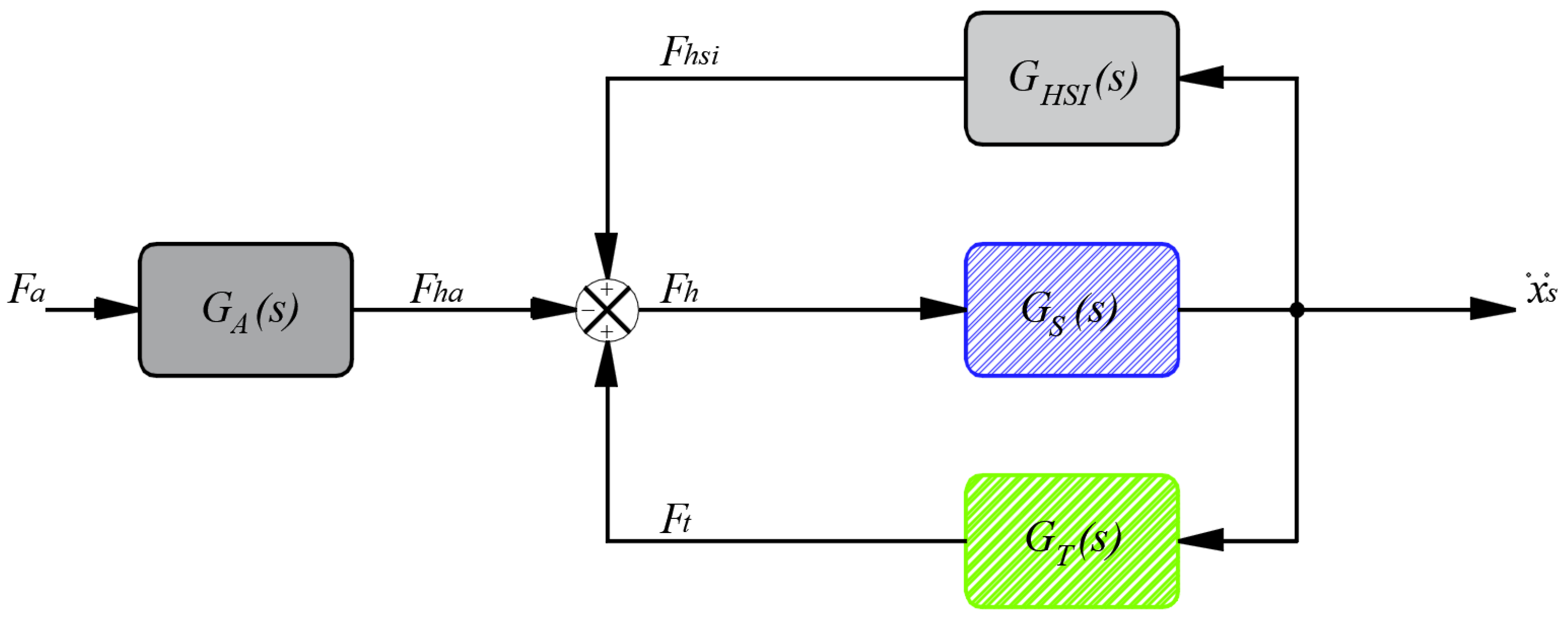
2. System Modeling
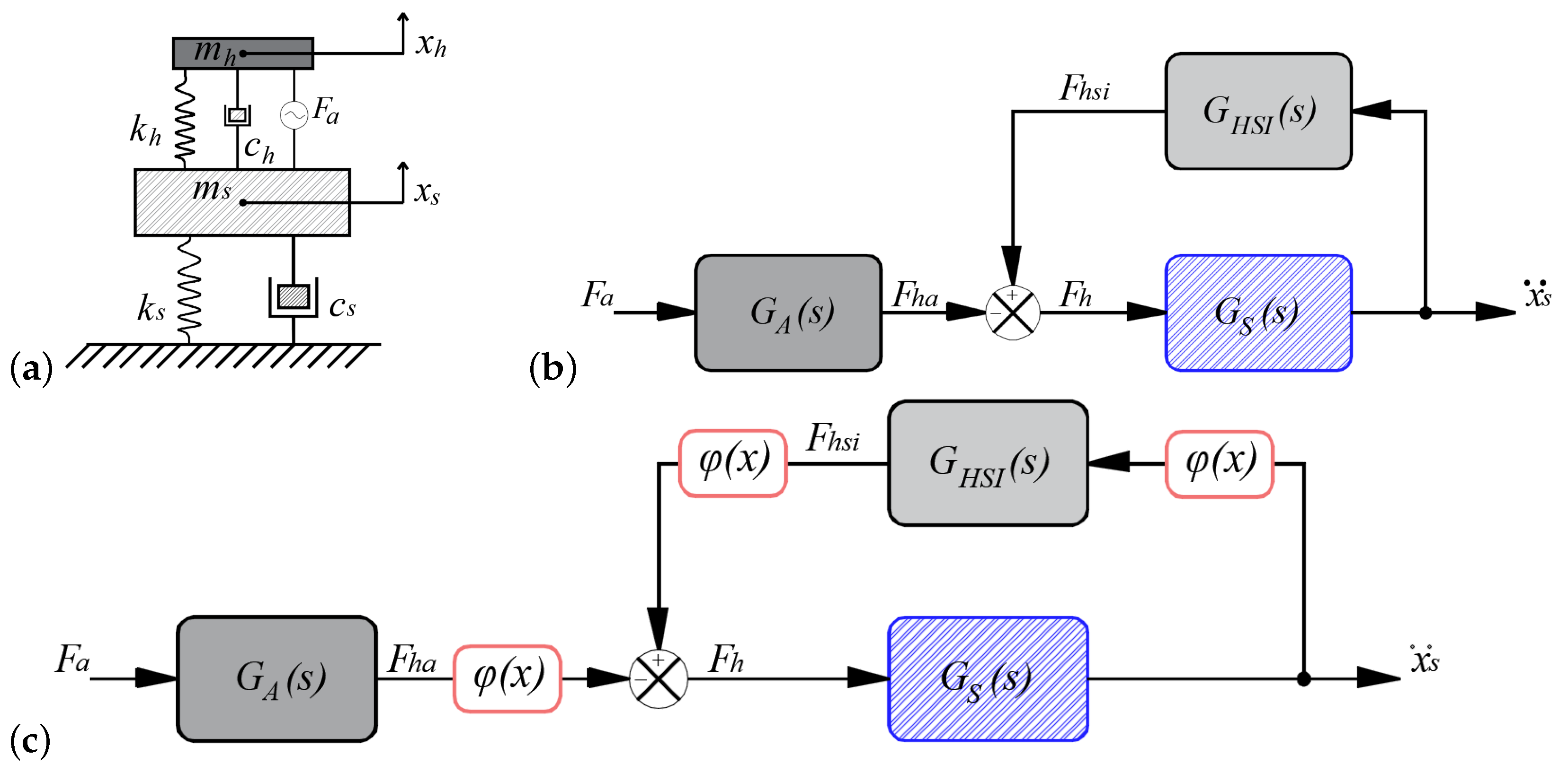
2.1. HSI Model
2.2. Passive TMD
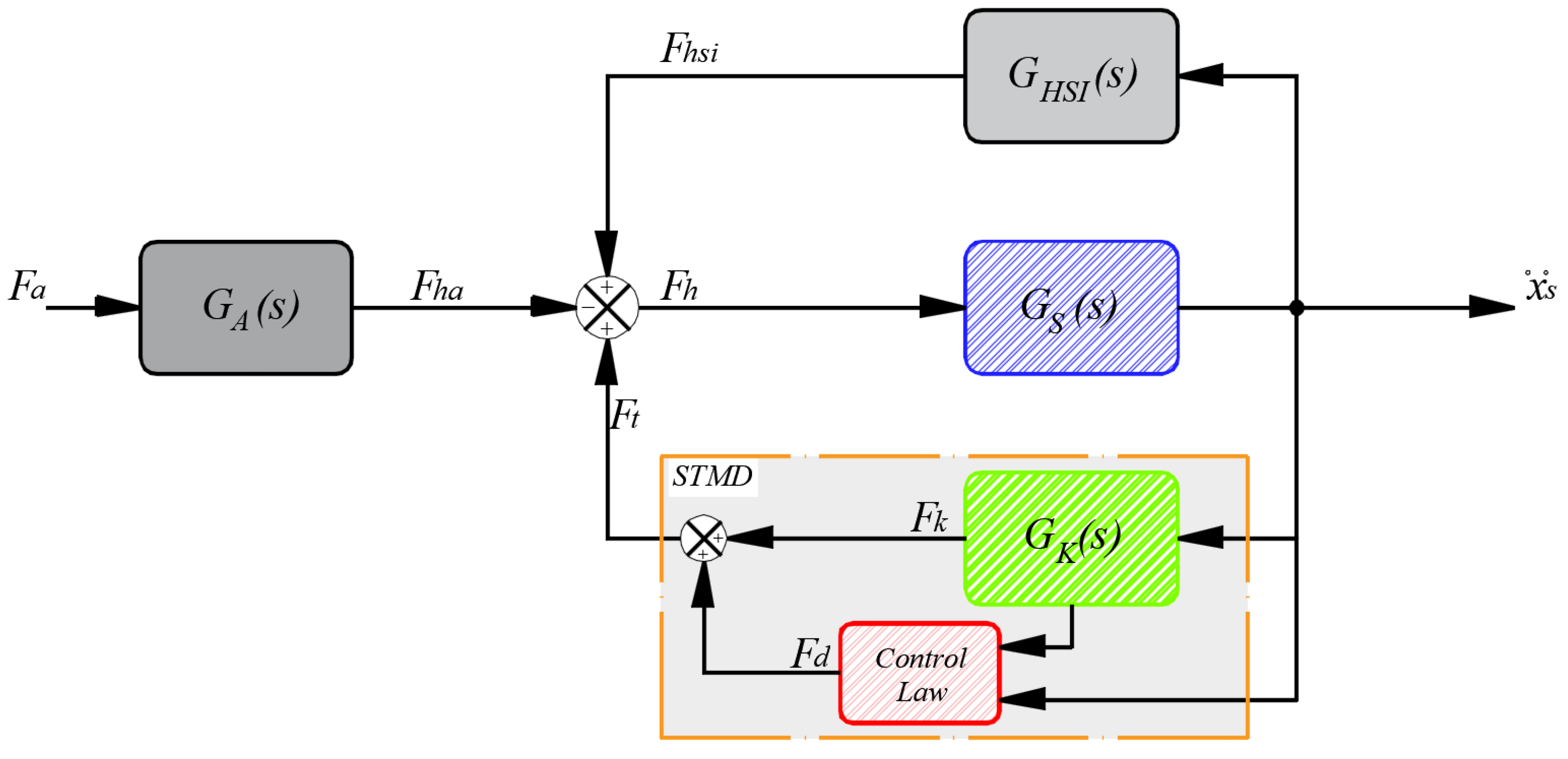
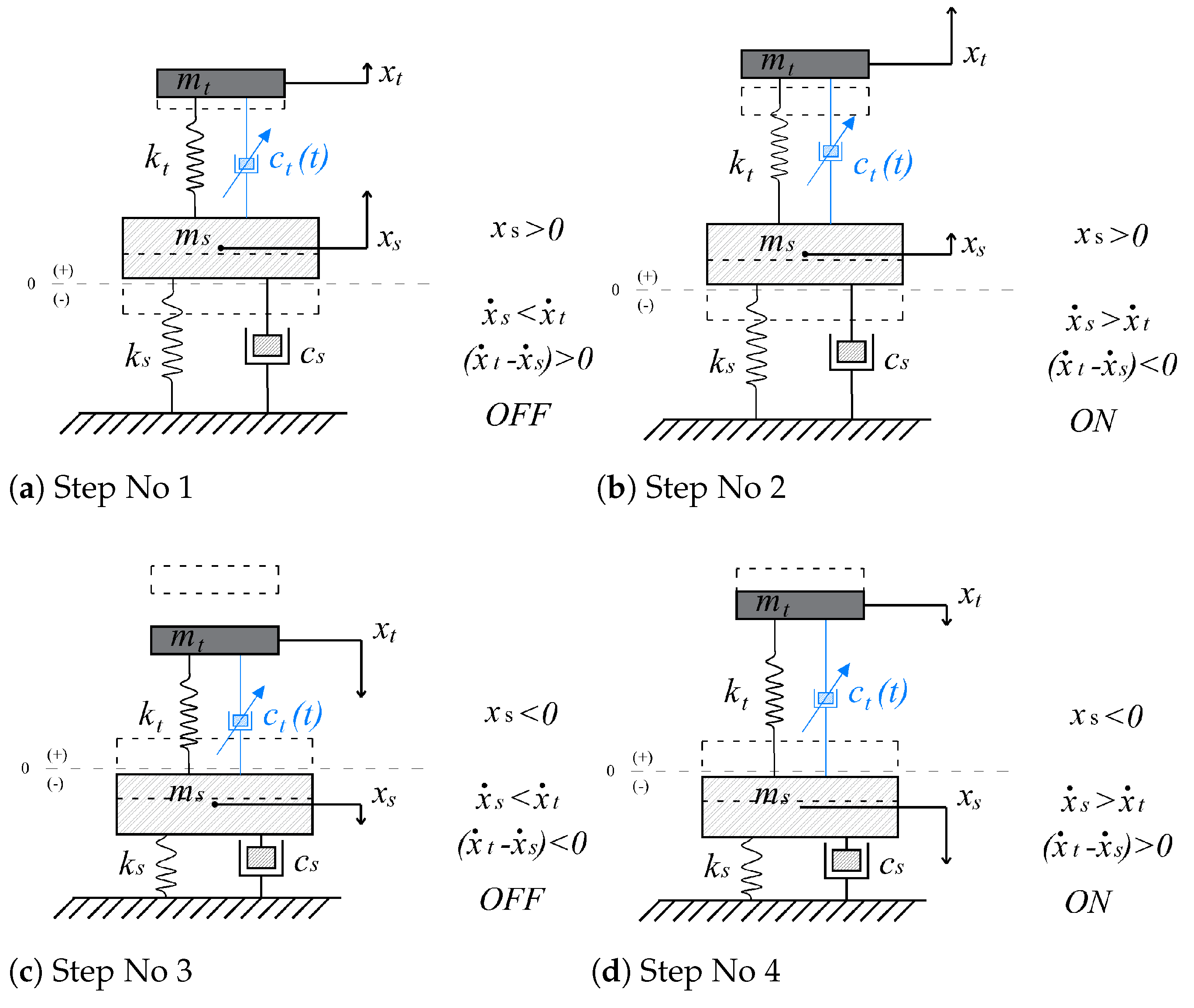
2.3. Semiactive TMD
Semiactive Control Law
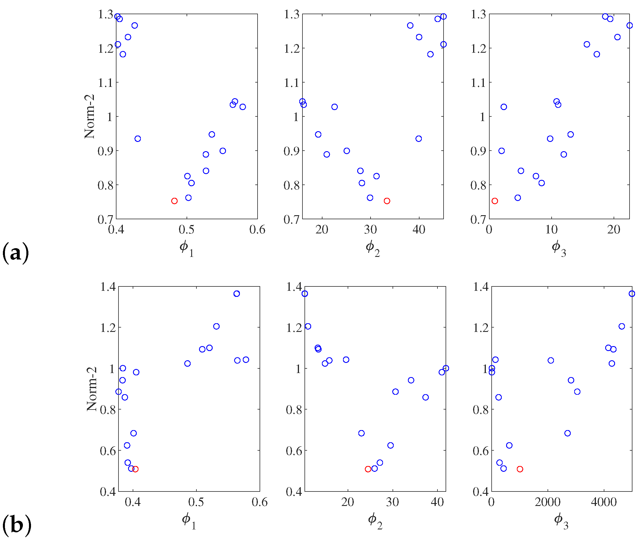
3. Optimum Design Procedure
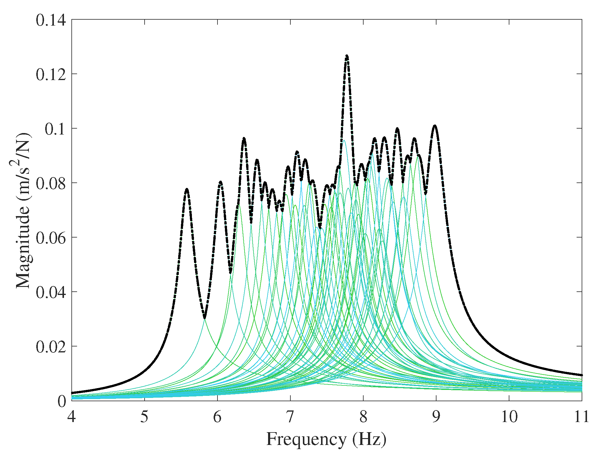
3.1. HSI Model
3.2. Performance Indexes and the Optimization Problem
- -
- Normalized Peak Acceleration:
- -
- Normalized 1s-RMS Acceleration:
- -
- Inertial Mass of the Control Device:
- -
- Saturation force:
4. Application of the Proposed Design Methodology
4.1. HSI Model
4.2. Optimum Design
4.3. Discussion of Results
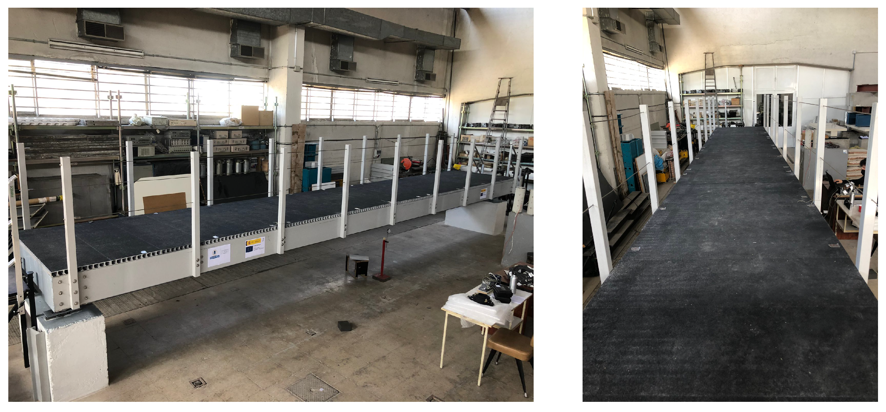
5. Application of the Proposed Design Methodology under Realistic Conditions
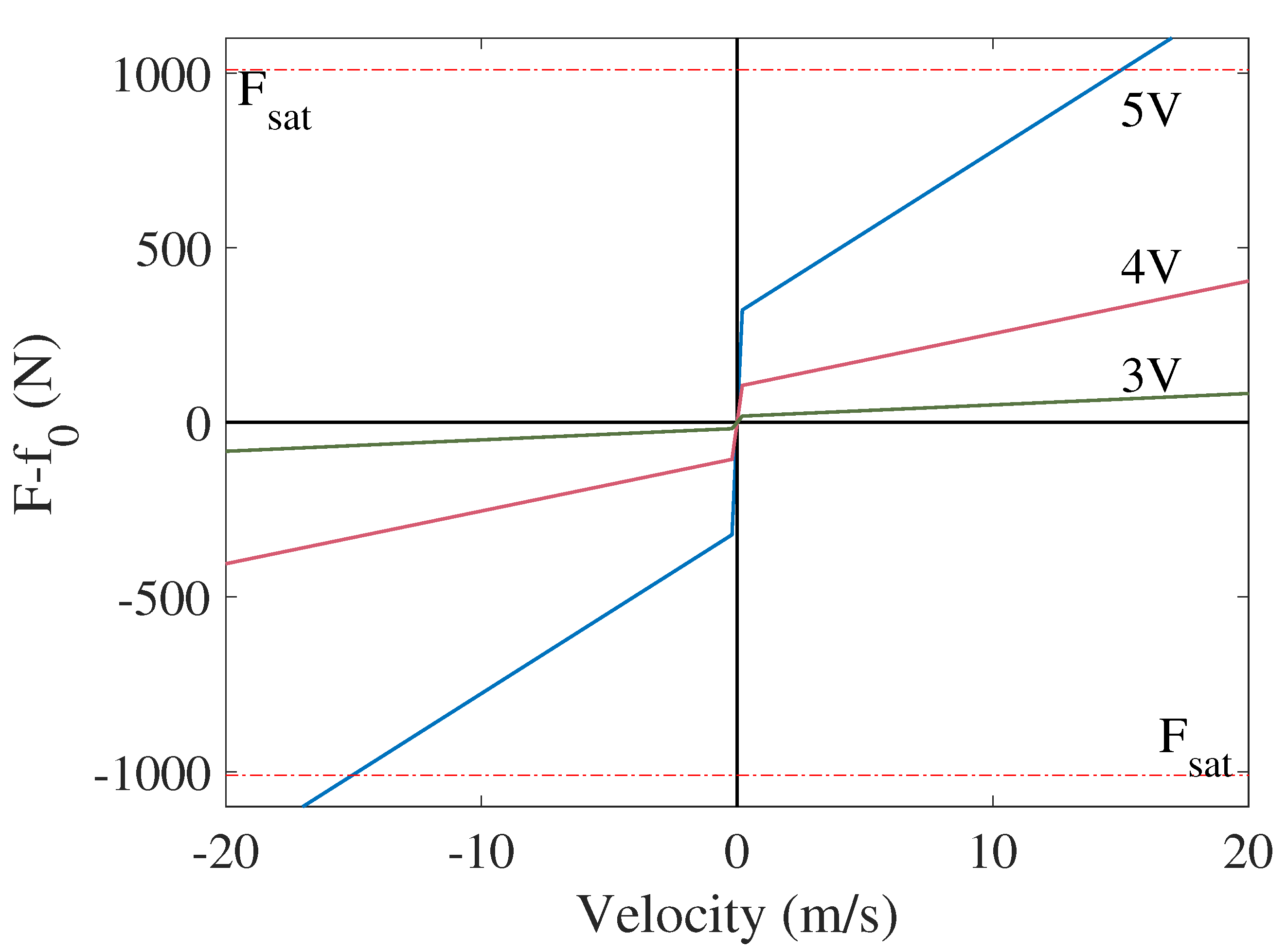
5.1. MR Modeling
5.2. Implementation of the Control Law
5.2.1. Low-Pass Filter
5.2.2. Integrator Filter
5.2.3. Deactivation Rule
5.3. Optimum Design under Realistic Conditions
6. Conclusions
Author Contributions
Funding
Institutional Review Board Statement
Informed Consent Statement
Data Availability Statement
Acknowledgments
Conflicts of Interest
Abbreviations
| FRP | Fiber-Reinforced Polymers |
| TMD | Tuned Mass Damper |
| STMD | Semiactive Tuned Mass Damper |
| HSI | Human–Structure Interaction |
| MSDA | Mass-Spring-Damper-Actuator |
| MTMD | Multiple Tuned Mass Damper |
| MR | Magnetorheological |
| DLF | Dynamic Load Factors |
| GLF | Generated Load Factors |
| SDOF | Single Degree of Freedom |
| CDF | Cumulative Distribution Function |
References
- Wei, X.; Russell, J.; Ẑivanovic, S.; Mottram, J.T. Measured Dynamic Properties for FRP Footbridges and their Critical Comparison against Structures made of Conventional Construction Materials. Compos. Struct. 2019, 223, 110956. [Google Scholar]
- Gallegos-Calderón, C.; Naranjo-Pérez, J.; Díaz, I.M.; Goicolea, J.M. Identification of a Human-Structure Interaction Model on an Ultra-Lightweight FRP Footbridge. Appl. Sci. 2021, 11, 6654. [Google Scholar] [CrossRef]
- Díaz, I.M.; Gallegos-Calderón, C.; Ramírez Senent, J.; Renedo, C.M.C. Interaction Phenomena to Be Accounted for Human-Induced Vibration Control of Lightweight Structures. Front. Built Environ. 2021, 7, 658529. [Google Scholar] [CrossRef]
- Yang, F.; Sedaghati, R.; Esmailzadeh, E. Vibration Suppression of Structures using Tuned Mass Damper Technology: A State of the Art Review. Civ. Eng. J. 2020, 6. [Google Scholar] [CrossRef]
- Ramini, F.; Aghayari, R.; Samali, B. Application of Tuned Mass Dampers for Structural Vibration Control: A State of the Art Review. Civ. Eng. J. 2020, 6. [Google Scholar] [CrossRef]
- Soria, J.M.; Díaz, I.M.; García-Palacios, J.H. Vibration Control of a Time-Varying Modal-Parameter Footbridge: Study of Semi-Active Implementable Strategies. Smart Struct. Syst. 2017, 20, 525–537. [Google Scholar]
- Demetriou, D.; Nikitas, N.; Tsavdaridis, K.D. Semi Active Tuned Mass Damper of Buildings: A Simple control Option. Am. J. Eng. Appl. Sci. 2015, 8, 620–632. [Google Scholar] [CrossRef]
- Van Nimmen, K.; Verbeke, P.; Lombaert, G.; De Roeck, G.; Van den Broeck, P. Numerical and Experimental Evaluation of the Dynamic Performance of a Footbridge with Tuned Mass Dampers. J. Bridge Eng. 2016, 21, C4016001. [Google Scholar] [CrossRef]
- Caetano, E.; Cunha, Á.; Moutinho, C.; Magalhães, F. Studies for Controlling Human-Induce Vibration of the Pedro e Inês Footbridge, Portugal. Part 2: Implementation of Tuned Mass Dampers. Eng. Struct. 2010, 32, 1082–1091. [Google Scholar] [CrossRef]
- Weber, F.; Maślanka, M. Precise Stiffness and Damping Emulation with MR Dampers and its Application to Semi-Active Tuned Mass Dampers of Wolgograd Bridge. Smart Mater. Struct. 2014, 23, 015019. [Google Scholar] [CrossRef]
- Koo, J.H.; Ahmadian, M.; Setareh, M.; Murray, T.M. In Search of Suitable Control Methods for Semi-Active Tuned Vibration Absorbers. J. Vib. Control 2004, 10, 163–174. [Google Scholar] [CrossRef]
- Moutinho, C. Testing a Simple Control Law to Reduce Broadband Frequency Harmonic Vibrations using Semi-Active Tuned Mass Dampers. Smart Mater. Struct. 2015, 24, 055007. [Google Scholar] [CrossRef]
- Zhang, D.; Pan, P.; Zeng, Y.; Guo, Y. A Novel Robust Optimum Control Algorithm and Its Application to Semi Active Controlled Base Isolated Structures. Bull. Earthq. Eng. 2020, 18, 2431–2460. [Google Scholar] [CrossRef]
- Gu, X.; Yu, Y.; Li, Y.; Li, J.; Askari, M.; Samali, B. Experimental Study of Semi-Active Magnetorheological Elastomer Base Isolation System using Optimal Neuro Fuzzy Logic Control. Mech. Syst. Signal Process. 2019, 119, 380–398. [Google Scholar] [CrossRef]
- Wang, L.; Nagarajaiah, S.; Shi, W.; Zhou, Y. Semi-Active Control of Walking-Induced Vibrations in Bridges using Adaptive Tuned Mass Damper considering Human-Structure-Interaction. Eng. Struct. 2021, 244, 112743. [Google Scholar] [CrossRef]
- Maślanka, M. Optimised Semi-Active Tuned Mass Damper with Acceleration and Relative Motion Feedbacks. Mech. Syst. Signal Process. 2019, 130, 707–731. [Google Scholar] [CrossRef]
- Pinkaew, T.; Fujino, Y. Effectiveness of Semi-Active Tuned Mass Dampers under Harmonic Excitation. Eng. Struct. 2001, 23, 850–856. [Google Scholar] [CrossRef]
- Barrera-Vargas, C.A.; Díaz, I.M.; Soria, J.M.; García-Palacios, J.H. Enhancing Friction Pendulum Isolation Systems Using Passive and Semi-Active Dampers. Appl. Sci. 2020, 10, 5621. [Google Scholar] [CrossRef]
- Ferreira, F.; Moutinho, C.; Cunha, Á.; Caetano, E. Use of Semi-Active Tuned Mass Dampers to Control Footbridges Subjected to Synchronous Lateral Excitation. J. Sound Vib. 2019, 446, 176–194. [Google Scholar] [CrossRef]
- Setareh, M.; Ritchey, J.K.; Koo, J.-H.; Admadian, M. Semiactive Tuned Mass Damper for Floor Vibration Control. J. Struct. Eng. 2007, 133, 242–250. [Google Scholar] [CrossRef]
- Weber, F.; Distl, H.; Fischer, S.; Braun, C. MR Damper Controlled Vibration Absorber for Enhanced Mitigation of Harmonic Vibrations. Actuators 2016, 5, 27. [Google Scholar] [CrossRef]
- Díaz, I.M.; Reynolds, P. On-off Nonlinear Active Control of Floor Vibrations. Mech. Syst. Signal Process. 2010, 24, 1711–1726. [Google Scholar] [CrossRef]
- Dougill, J.W.; Wright, J.R.; Parkhouse, J.G.; Harrison, R.E. Human Structure Interaction during Rhythmic Bobbing. Struct. Eng. 2006, 84, 32–39. [Google Scholar]
- ACMA. Pre Standard for Load and Resistance Factor Design (LRFD) of Pultruded Fiber Reinforced Polymer (FRP) Structure; American Society of Civil Engineers ASCE: Reston, VA, USA, 2010. [Google Scholar]
- Shahabpoor, E.; Pavic, P.; Racic, V. Interaction between Walking Humans and Structure in Vertical Direction: A Literature Review. Shock Vib. 2016, 2016, 3430285. [Google Scholar] [CrossRef] [Green Version]
- Zhang, M.; Georgakis, C.T.; Chen, J. Biomechanically Excited SMD Model of a Walking Pedestrian. J. Bridge Eng. 2016, 21, C4016003. [Google Scholar] [CrossRef]
- Ahmadi, E.; Caprani, C.; Ẑivanovic, S.; Heidarpour, A. Experimental Validation of Moving Spring-Mass-Damper Model for Human-Structure Interaction in the Presence of Vertical Vibrations. Structures 2021, 29, 1274–1285. [Google Scholar] [CrossRef]
- European Commission, Directorate-General for Research and Innovation; Feldmann, M.; Heinemeyer, C.; Butz, C. Advanced Load Models for Synchronous Pedestrian Excitation and Optimised Design Guidelines for Steel Footbridges; Publications Office: Luxembourg, 2009. [Google Scholar]
- Blasco, X.; Herrero, J.M.; Sanchis, J.; Martínez, M. A New Graphical Visualization of N-Dimensional Pareto Front for Decision-Making in Multiobjective Optimization. Inf. Sci. 2008, 128, 3908–3924. [Google Scholar] [CrossRef]
- Aguirre, N. Magnetorheological Dampers: Modeling and Control Design for Civil Engineering Structure; Universitat Politècnica de Catalunya: Barcelona, Spain, 2011. [Google Scholar]
- Barrera-Vargas, C.A.; Díaz, I.M.; García-Palacios, J.H.; Soria, J.M. Semi-active Tuned Mass Damper. Magnetorheological Damper Identification and Performance Evaluation. In Proceedings of the 2nd Conference on Structural Dynamics, Gijón, Spain, 22–23 July 2021; pp. 172–182. [Google Scholar]
- Soria, J.M.; Díaz, I.M.; García-Palacios, J.H. Further steps towards the tuning of inertial controllers for broadband-frequency-varying structures. Struct Control Health Monit. 2020, 27, e2461. [Google Scholar] [CrossRef]
- Díaz, I.M.; Reynolds, P. Robust Saturated Control of Human-Induced Floor Vibrations via a Proof-Mass Actuator. Smart Mater. Struct. 2009, 18, 125024. [Google Scholar] [CrossRef] [Green Version]


| Structure | Value | Units | |
|---|---|---|---|
| Mass | to | kg | |
| Frequency | to | Hz | |
| Damping ratio | to | % | |
| Damping coefficient | to | kg/s | |
| Stiffness | to | N/m | |
| Human | Value | Units | |
| Mass | to | kg | |
| Frequency | Hz | ||
| Damping ratio | to | % | |
| Damping coefficient | to | kg/s | |
| Stiffness | to | N/m | |
| Design Variable | Lower Bound | Upper Bound | |
|---|---|---|---|
| Mass (kg) | 10 | 45 | |
| Frequency (Hz) | 1.00 | 10.00 | |
| Damping ratio (%) | 1 | 50 | |
| Saturation force (N) | 10 | 5000 | |
| TMD | Value | ||
|---|---|---|---|
| Mass | 33.36 | kg | |
| Frequency | 9.95 | Hz | |
| Damping ratio | 1.03 | % | |
| Damping coefficient | 42.96 | kg/s | |
| Stiffness | N/m | ||
| Objective function | - | ||
| STMD | Value | ||
| Mass | 24.50 | kg | |
| Frequency | 6.15 | Hz | |
| Normal functioning | 37.91 | kg/s | |
| Blocking functioning | 1895.7 | kg/s | |
| Stiffness | N/m | ||
| Saturation force | N | ||
| Objective function | - | ||
| STMD MR | Value | ||
|---|---|---|---|
| Mass | 24.38 | kg | |
| Frequency | 6.00 | Hz | |
| Stiffness | N/m | ||
| Saturation force | N | ||
| Objective function | - | ||
Publisher’s Note: MDPI stays neutral with regard to jurisdictional claims in published maps and institutional affiliations. |
© 2022 by the authors. Licensee MDPI, Basel, Switzerland. This article is an open access article distributed under the terms and conditions of the Creative Commons Attribution (CC BY) license (https://creativecommons.org/licenses/by/4.0/).
Share and Cite
Barrera-Vargas, C.A.; Naranjo-Pérez, J.; Díaz, I.M.; García-Palacios, J.H. Design of a Semiactive TMD for Lightweight Pedestrian Structures Considering Human–Structure–Actuator Interaction. Actuators 2022, 11, 101. https://doi.org/10.3390/act11040101
Barrera-Vargas CA, Naranjo-Pérez J, Díaz IM, García-Palacios JH. Design of a Semiactive TMD for Lightweight Pedestrian Structures Considering Human–Structure–Actuator Interaction. Actuators. 2022; 11(4):101. https://doi.org/10.3390/act11040101
Chicago/Turabian StyleBarrera-Vargas, Christian A., Javier Naranjo-Pérez, Iván M. Díaz, and Jaime H. García-Palacios. 2022. "Design of a Semiactive TMD for Lightweight Pedestrian Structures Considering Human–Structure–Actuator Interaction" Actuators 11, no. 4: 101. https://doi.org/10.3390/act11040101
APA StyleBarrera-Vargas, C. A., Naranjo-Pérez, J., Díaz, I. M., & García-Palacios, J. H. (2022). Design of a Semiactive TMD for Lightweight Pedestrian Structures Considering Human–Structure–Actuator Interaction. Actuators, 11(4), 101. https://doi.org/10.3390/act11040101