Article

Vibration Control of a High-Rise Slender Structure with a Spring Pendulum Pounding Tuned Mass Damper

1
School of Civil Engineering, Shenyang Jianzhu University, Hunnan District, Shenyang 110168, China
2
Department of Road and Bridge Engineering, Liaoning Provincial College of Communications, Shenyang 110168, China
3
State Laboratory of Coastal and Offshore Engineering, Faculty of Infrastructure Engineering, Dalian University of Technology, Ganjingzi District, Dalian 116024, China
4
Institute of Road and Bridge Engineering, Dalian Maritime University, Dalian 116023, China
*
Author to whom correspondence should be addressed.
Actuators 2021, 10(3), 44; https://doi.org/10.3390/act10030044
Submission received: 4 February 2021 / Revised: 17 February 2021 / Accepted: 24 February 2021 / Published: 28 February 2021

Abstract

:
High-rise structures are normally tall and slender with a large height-width ratio. Under the strong seismic action, such a structure may experience violent vibrations and large deformation. In this paper, a spring pendulum pounding tuned mass damper (SPPTMD) system is developed to reduce the seismic response of high-rise structures. This SPPTMD system consists of a barrel limiter with the built-in viscoelastic material and a spring pendulum (SP). This novel type of tuned mass damper (TMD) relies on the internal resonance feature of the spring pendulum and the collision between the added mass and barrel limiter to consume the energy of the main structure. Based on the Hertz-damper model, the motion equation of the structure-SPPTMD system is derived. Furthermore, a power transmission tower is selected to evaluate the vibration reduction performance of the SPPTMD system. Numerical results revealed that the SPPTMD system can effectively reduce structural vibrations; the reduction ratio is greater than that of the spring pendulum. Finally, the influence of the key parameters on the vibration control performance is conducted for future applications.

1. Introduction

High-rise infrastructures such as skyscrapers, wind turbines, radio or television towers and power transmission towers are featured by its low damping and high vulnerability under seismic hazards. Damages or collapse of high-rise structures have been extensively reported in post-earthquake investigations. For example, in the Kobe earthquake of 1995 and the Wenchuan earthquake of 2008, more than a dozen transmission towers were damaged [1]. Similarly, strong winds can also cause the collapse of large wind turbine towers [2] and antenna towers [3]. Mitigation of the undesired vibrations of these structures can effectively improve the structural safety and reliability.
In engineering, controlling the vibration of high-rise structures is an effective practice for reducing the dynamic responses of these structures. A variety of damping devices and damping algorithms has been proposed, including eddy current damper [4,5,6,7], electromagnetic damper [8], LQR controller [9], magnetorheological damper [10], tuned liquid column damper [11], particle damper [12,13], etc. Among these damping devices, the tuned mass damper (TMD) is widely accepted due to its simple structure, low cost and convenient installation. When the primary structure is forced into motion, the TMD can generate an inertial force to reduce the structural vibration. In recent years, scholars have conducted considerable research on the TMD and proposed many new type TMD devices, such as the annular TMD [14], pendulum TMD [15,16], frictional TMD [17], viscoelastic TMD [18,19]. Weber et al. [20,21] designed a semi-active tuned mass damper with magnetorheological damper, which can control structures that vibrate at different frequencies. Scholars used piezoelectric ceramics to change the curvature of the bending beam [22] and the prestress imposed on the steel plate [23] to change the stiffness of the damper, thereby achieving effective vibration control of the structure within a certain frequency range. A TMD based on a piezoelectric transducer has been proposed. The advantage of this damper is that it has adaptive resonance frequency and damping, and low energy consumption [24]. To improve the vibration resistance of the dampers, scholars also introduced shape memory alloys [25,26,27,28] into the TMD. Tian et al. proposed a type of TMD composed of nonlinear shape memory alloys [29]. Salvi et al. [30] performed a parametric study of the TMD and achieved optimal design. Chen et al. [31] studied an eddy current tuned mass damper (ECTMD). Elias et al. [32] reduced the wind vibration of chimneys by TMD. In order to further improve the performance of TMDs [33] and avoid performance degradation due to changes in their system parameters [34,35], scholars have also investigated multi-TMDs [36,37].
The passive control methods are the most widely applied to the field of civil engineering [38,39]. Since the TMD is a linear vibration absorber, its frequency band of vibration suppression is relatively narrow compared with the nonlinear vibration absorbers [40]. Therefore, previous researchers have introduced nonlinear components, such as the cubic spring [41], pounding components [42,43,44], internal resonance [45] or nonlinear short wire ropes [46] to the classical TMD device, so as to widen its frequency band.
The pounding tuned mass damper (PTMD), which consists of a mass block and a limiter, is a typical nonlinear damper. The PTMD utilizes the inertial force of the added mass and the collision between the added mass and limiter to consume the kinetic energy of the structure and then achieve vibration control effect. Previous studies have shown that the PTMD is superior to traditional TMD in vibration control for the high-rise slender structures, and it has the advantages of a wider vibration suppression frequency band [47,48] and better robustness [49]. Therefore, the PTMD has been widely applied to control vibrations in various structures, such as power transmission towers [50], frame structures [51], traffic signal structures [52], bridges [53,54,55], pipeline structures [56,57,58], voided biaxial concrete slab [59] and stay cable [60]. Additionally, scholars have verified their effectiveness through experiments [61,62] and numerical simulations. Collete [63] et al. confirmed the oscillation suppression effectiveness of a tuned absorber combined with an impact damper. Wang et al. [64] performed numerical methods to simulate the energy consumption process of absorber. Li et al. [49] examined the robustness and seismic performance of the PTMD using numerical methods and experimental studies. Lin et al. [65] analyzed the vibration reduction effect of the PTMD and multiple PTMDs (MPTMDs) on the basis of a modified pounding force model [66]. Furthermore, in order to control the wind-induced response of the transmission tower, Fu et al. [67] devised a new pounding spacer damper (PSD). More recently, a bidirectional PTMD [68] and a damper with zero distance from the tuned mass to the collision boundary [69] have been presented. The combination of a PTMD and a shape memory alloy are used by Ghasemi et al. [70] to reduce the vibration of offshore jacket platforms.
The spring pendulum (SP) composing of a mass block hanged by a spring is another typical nonlinear damper [71,72]. Motion of the mass block can be decomposed into two vibration modes: (1) the radial vibration mode, in which the mass block vibrates along the radius direction; (2) the swing mode, in which the mass block swings in the tangential direction, as a classical pendulum. If a specific relation between the spring stiffness and pendulum length is satisfied, an internal resonance phenomenon will occur, in which vibration energy will be transferred between the two modes, i.e., the internal resonance phenomenon [73]. A previous study has demonstrated that the SP can effectively reduce structural vibration [45] and is superior to the traditional TMD in vibration absorption. Nevertheless, the additional damping element is not included in the previous SP damper. Consequently, its energy dissipation capacity is still insufficient and introducing an additional damping may further improve the vibration control effectiveness. Collision between the added mass of the SP and some limiter can be a beneficial method of introducing additional energy dissipation. Therefore, this paper incorporates the collision into the SP and proposes a new type damper, namely the spring pendulum pounding tuned mass damper (SPPTMD). The SPPTMD is composed of a connecting plate, a mass, spring and a limiter built-in viscoelastic material. Compared with the traditional TMD, energy absorbing ability of the SPPTMD was enhanced by the internal resonance phenomenon. Compared with the SP damper, the energy dissipation of the SPPTMD was enhanced by the collision.
The remaining parts of this article are arranged as follows. Section 2 introduces the configurations and mechanism of the SPPTMD system. Section 3 deduces the equations of motion for the SPPTMD system and the structure-SPPTMD system based on the Hertz-damp model. Section 4 verifies the effectiveness of the SPPTMD system by considering a transmission tower model excited by three real earthquake waves. Section 5 discusses the oscillation mitigation effectiveness of the SPPTMD due to variations in pounding stiffness, mass ratio, damping ratio and gap, which were undertaken analytically. Finally, a summary is provided in Section 6 to close this paper.

2. Mechanism of the SPPTMD

The SPPTMD is a novel damping device developed on the basis of suspended mass pendulum (SMP) and SP. In order to clearly demonstrate the mechanism of the proposed SPPTMD, schematics of the SMP, the SP and the SPPTMD are all illustrated and compared in this section.

2.1. Mechanism of the SMP

As is illustrated in Figure 1, the suspended mass pendulum (SMP) is basically a suspended mass block connected to the structure to be controlled by a cable. The length of the cable is carefully designed to adjust the frequency of the SMP to match the frequency of the structure, in order to obtain optimal damping effectiveness. The length of the cycloid can be calculated by the following Equation [16]:
l = g / ( 2 π f ) 2 ,
where g = 9.8   m / s 2 is gravitational acceleration; f is the frequency of the primary structure.

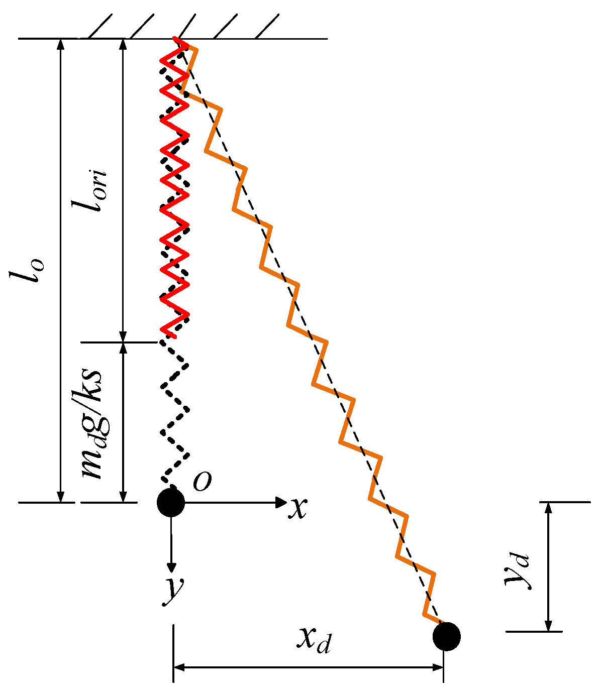
2.2. Mathematical Model of the SP

The SP can be regarded as a modified SMP, which replaces the suspending cable with a linear spring. In previous studies [45,71,72], the motion equation of the SP has been derived to analyze its behavior. Suppose the original length and the stiffness of the spring are l o r i and k s , respectively. When the mass is subjected to gravity, length of the spring will be stretched to l 0 (as shown in Figure 2):
l o r i = l 0 m d g k s
Suppose this position is the origin point O and establishing a coordinate (Figure 2), the motion equation is as follows:
{ x ¨ d + k s x d m d ( 1 l o r i x d 2 + ( y d + l o ) 2 ) = 0 y ¨ d + k s m d ( y d + l o ) ( 1 l o r i x d 2 + ( y d + l o ) 2 ) g = 0
where x d and y d denote the displacement of the SP in the horizontal and vertical direction; k s is the stiffness of the spring; m d is the mass of the mass block; l o r i is the original length of the spring; l 0 denotes the length of the spring under the load of gravity; g = 9.8   m / s 2 is gravitational acceleration.
At any moment, the spring will add a nonlinear restoring force to the mass block of the SP in both x and y directions:
{ f x = k s x d ( 1 l o r i x d 2 + ( y d + l o ) 2 ) f y = k s y d ( 1 l o r i x d 2 + ( y d + l o ) 2 ) m d g
Since the mass block is suspended by a spring in the SP, it has two coupled vibration modes: the radial vibration mode and the swing vibration mode. The radial vibration mode allow the mass block to move in the radius direction, while in the swing mode, the mass block moves like a pendulum (Figure 3). The circular frequency of the radial mode is determined by the mass and stiffness of the spring:
ω s = k s m
in which ω s is the circular frequencies of the radial vibration mode; k s is the stiffness of the spring; m is the mass of the mass block. In the swing mode, the mass block vibrates like a pendulum; the circular frequency of this mode can be determined by:
ω p = g l 0
where ω p is the circular frequencies of the swing mode; l 0 is the length of the spring under the load of gravity.
In previous studies, it is found that if the ratio of ω s over ω p is near 2, the two vibration modes are strongly coupled, and energy can be transfered between these two modes. This phenomenon is named as internal resonance and
λ = ω s ω p = 2
is named as internal resonance condition. In order to verify the motion equation of the SP, a numerical model is established in MATLAB and the trajectory of an SP subjected to an initial displacement is calculated and illustrated in Figure 4. It can be seen that the trajectory of the SP is very consistent with the conclusion in the literature [71].
It should also be noted that the suspended mass pendulum can be regarded as a special SP, whose spring stiffness is very large; thus, the radial vibration mode is often neglected. Compared with the SMP, the SP has two strongly coupled vibration modes, which effectively increases its energy absorption ability.

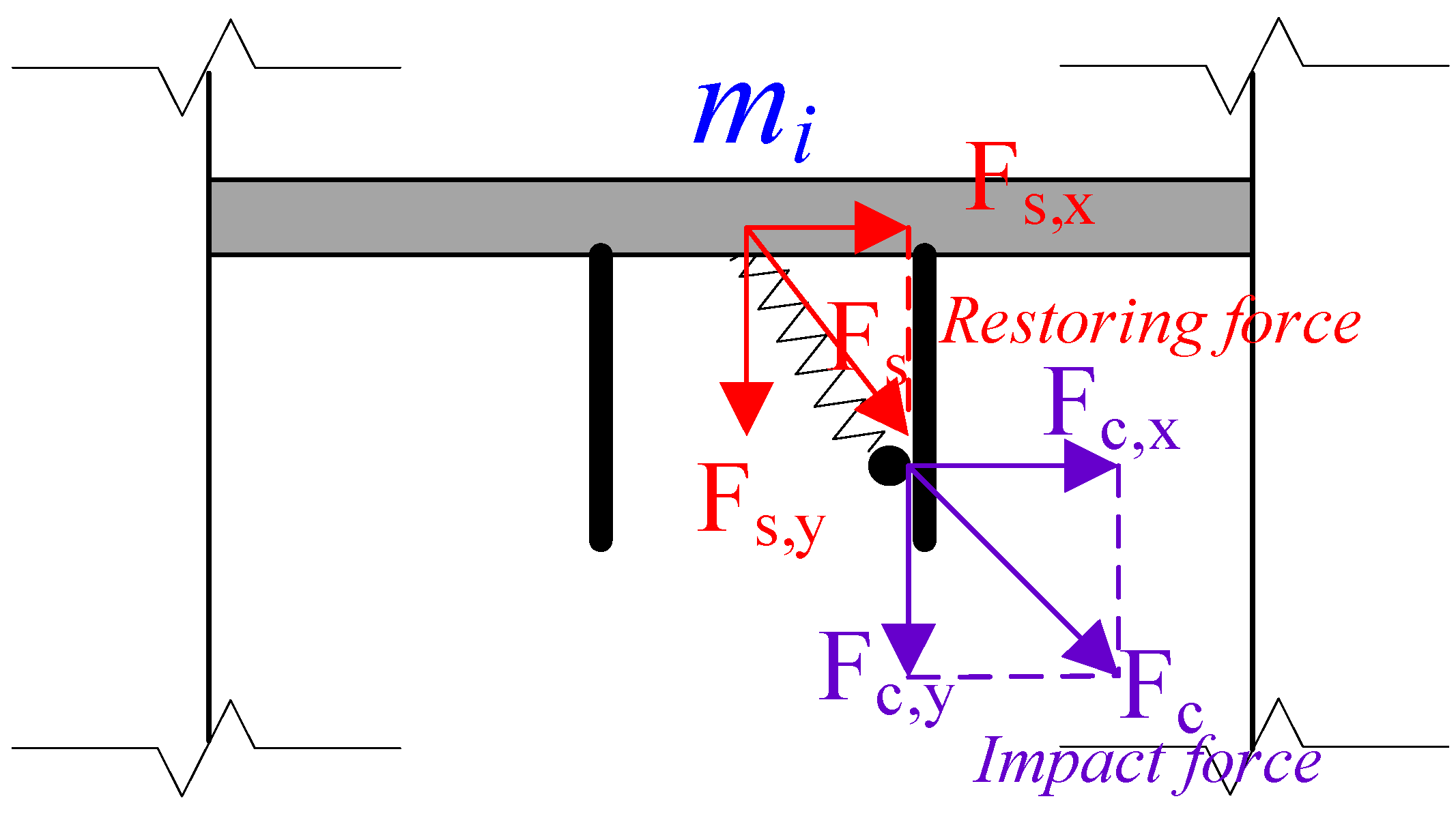
2.3. Mechanism of the SPPTMD

Though previous studies also demonstrate that its energy absorption ability of the SP is larger compared to the suspended mass pendulum, because the SP has an additional radial vibration mode [45], the energy dissipation capacity of the SP is still insufficient. Therefore, this paper incorporates the collision into the SP. As seen in Figure 5, the SPPTMD system consists of a connection plate, a mass block, a spring and a limiter with the built-in viscoelastic material. Among these components, the connection plate is employed to connect the SPPTMD system to the main structure, while the spring pendulum and the limiter are used to absorb the vibration energy; additionally, the viscoelastic material is applied to reduce the noise generated when the mass collides with the limiter, to avoid local damage of the limiter and to increase the energy consumption during collision. The vibration suppression principle of the SPPTMD system is as follows: (i) when the vibration of the primary structure is small, the mass of the SPPTMD absorbs the kinetic energy of the primary structure as a typical SP; (ii) when the vibration of the primary structure exceeds a certain level, the added mass collides on the limiter and dissipate the absorbed kinetic energy.

3. Numerical Model of the Structure-SPPTMD System

Figure 6 demonstrates an n-degree-of-freedom (DOF) structure equipped with an SPPTMD at the ith floor. It can be seen from Figure 7 that the is subjected to two forces, i.e., the restoring force (Fs) generated by the relative motion and the impact force (Fc) when the SPPTMD collides on the boundary.
Suppose the displacement of the ith DOF is x i , and the displacement of the SPPTMD is x d and y d in the horizontal and vertical direction. Then the relative displacement between the damper and the ith floor is
x r = x d x i
y r = y d
Similar to Equation (4), the restoring force generated by the relative motion is:
{ F s , x = k s x r ( 1 l o r i x r 2 + ( y r + l o ) 2 ) F s , y = k s y r ( 1 l o r i x r 2 + ( y r + l o ) 2 ) m d g
Suppose the gap between the SPPTMD and the boundary is g p , then the relative deformation of the elastic material attached to the surface of the boundary can be expressed as follows:
δ = { x r g p   if   impacts   the   right   boundary x r + g p   if   impacts   the   left   boundary
and the speed of the deformation is:
δ ˙ = x ˙ r
The impact force generated by the collision can be attained based on the Hertz contact model [50]:
F c = { β δ 1.5 + c δ β δ 1.5   if   δ ˙ > 0   if   δ ˙ < 0
in which β is the pounding stiffness and c is the impact damping. c can be calculated by
c = 2 ξ β m d m i m d + m i
where ξ is the impact damping ratio; m d and m i are the mass of the SPPTMD and the ith floor. ξ can be attained by:
ξ = 9 5 2 1 e 2 e [ e ( 9 π 16 ) + 16 ]
Here, e = h h is the restitution coefficient which can be determined by dropping a sphere on the surface of the elastic material and measure the initial height, h , and bounced height, h . In this paper, β = 17,000 N/m3/2 and e = 0.25 is obtained from previous experimental studies [50].
It should be noted that the mass block of the SPPTMD can impact either on the left side or the right side of the two boundaries. Therefore, F d i r is defined to indicate the direction of the pounding force:
F d i r = { 1 x d x i > g p   pounding   on   the   right   side 1 x d x i < g p   pounding   on   the   left   side 0   others   not   pounding
Based on Equations (8)–(16), the equations of motion for an n-degree-of-freedom structure equipped with an SPPTMD attached to the ith degree of freedom can be derived as follows:
{ M s x ¨ ( t ) + C s x ˙ ( t ) + K s x ( t ) = M s I x ¨ g ( t ) + L F s , x ( t ) + F d i r L F c , x ( t ) m d x ¨ d ( t ) = F s , x ( t ) F d i r F c , x ( t ) m d y ¨ d ( t ) = m d g F s , y ( t ) F c , y ( t )
where M s , C s and K s are the mass, damping and stiffness matrices of the undamped structure, respectively; x ¨ ( t ) , x ˙ ( t ) and x ( t ) are the acceleration, velocity and displacement vectors, respectively; I is a column vector of ones; x ¨ g is the ground acceleration; and L denotes the location of the SPPTMD; F s is the nonlinear force generated by the spring of the SPTMD; F d i r denotes the direction of the impact; F c is the nonlinear pounding force; m d is the mass of the mass block; x d and y d denote the displacement of the SPPTMD in the horizontal and vertical direction; F s , y and F c , y are the restoring force and the pounding force, respectively, of the spring pendulum in the y direction.
In Equation (17), suppose the SPPTMD is attached to the ith degree of freedom of the primary structure, then the location vector L is as follows:
L = ( 0 , 0 , , 1 t h e   i t h   e l e m e n t   e q u a l s   o n e , 0 , , 0 ) T
Equation (17) is modeled in a Simulink environment of MATLAB and solved by the ODE45, which is an embedded solver based on Runge–Kutta Method. The time step size is variable, with the maximum step size set to 0.02 s. All other parameters are set to the default values of the software.

4. Case Study

To demonstrate the vibration damping performance of the SPPTMD, a numerical analysis is performed based on a 53.9 m high power transmission tower [45], which is a typical high-rise structure. As shown in Figure 8, the transmission tower is simplified by 15 DOFs, and has a mass of 19,621 kg and a natural frequency of 1.87 Hz. The layout of the SPPTMD on the transmission tower is illustrated in Figure 9.
In this paper, three recorded ground motions are chosen according to Chinese Code for designing transmission tower structures [74], to verify the effectiveness of the proposed SPPTMD, with their peak acceleration adjusted to 400 cm/s2. The detailed information of the selected seismic records is shown in Table 1. Afterward, the damping performance of an SMP, an SP and an SPPTMD with the same mass ratio are compared. The following parameters are assumed for the numerical study: the mass ratio is 2%, the damping ratio is 2%, β = 17,000 N/m3/2, gp = 0.05 m. The seismic responses of the tower under the various earthquake waves are shown in Figure 10, Figure 11 and Figure 12.
To quantify the damping performance of the SPPTMD, the vibration reduction ratio is defined as follows:
η d = ( D 0 D 1 ) D 0 × 100 %
η a = ( A 0 A 1 ) A 0 × 100 %
where D 1 and D 0 represent the displacements of the tower with and without control, respectively; and A 1 and A 0 are the acceleration responses of the tower with and without control, respectively. Table 2 lists the peak value and the root mean square (RMS) value of the seismic response of the tower.
It can be seen from Figure 10, Figure 11 and Figure 12 that the vibration reduction ratio of SP and SPPTMD are slightly better compared with SMP. Especially in terms of the vibration reduction ratios of the displacement, SP and SPPTMD increased by more than 6% and 16%, respectively. Figure 10 indicates that the SP and the SPPTMD can both reduce the vibration caused by earthquakes on transmission tower. However, the displacement and acceleration reduction ratios of the SPPTMD are larger than that of the SP. Compared to the SP, the vibration reduction ratios of the displacement and acceleration are increased by 10.4% and 0.1%, respectively, with the SPPTMD. The damping performance of the SPPTMD is better than the SP because the pounding between the added mass and the delimiter provided additional energy dissipation approach. Generally, the ability of the damper to reduce displacement is better than the acceleration. In terms of the RMS value of the displacement and acceleration, more effective suppression is achieved by the SPPTMD, with vibration reduction ratios of 55% and 41.9%, whereas those of the SP are only 48.4% and 34.7%, respectively.
Figure 11 and Figure 12 show the better results. Under EQ2, the reduction ratios of the displacement, acceleration, RMS of the displacement and RMS of the acceleration are 37.3%, 18%, 30.8% and 32.5%, respectively, when the SPPTMD is applied, which are greater than those of the SP, i.e., 29.8%, 15.3%, 27.4% and 29.9%. Similarly, under EQ3, compared to the SP, the displacement and acceleration reduction ratios of the transmission tower can be increased by the SPPTMD from 20.9% to 32.0% and from 25.4% to 34.9%, respectively. With regard to the RMS value of the displacement and acceleration, greater reduction ratios are also observed with the SPPTMD, increasing from 42.4% to 49.7% and from 41.6% to 49.5%, respectively. Obviously, numerical results indicate that the SPPTMD has a slightly improved vibration control performance under various earthquakes.

5. Parametric Study

Although the vibration reduction performance of the proposed SPPTMD has been verified numerically in the above Section 4, the influences of this damper’s key parameters are not discussed. In this section, the pounding stiffness, the mass ratio, the gap between the added mass and the limiter and the damping ratio of the primary structure are selected as the key design parameters of the SP; their influence on the vibration reduction ratio are discussed to achieve further understanding of the damper and provide some suggestion for optimal design. Unless mentioned otherwise, all parameters have the same values as in Section 4.

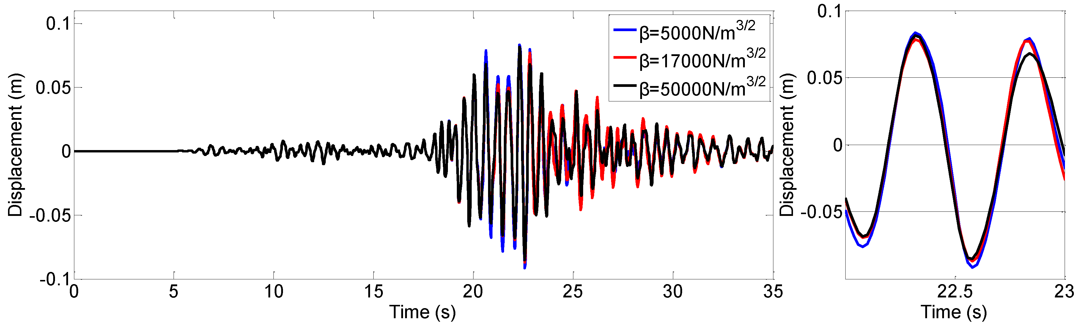
5.1. Pounding Stiffness

The pounding stiffness of the viscoelastic materials is an important parameter in the numerical study. Its value may influence the vibration control effect of the proposed SPPTMD. Therefore, in this section, three values ( β = 5000   N / m 3 / 2 , β = 17,000 N/m3/2 and β = 50,000 N/m3/2) were used to study its influence and the vibration reduction ratio η d is employed to interoperate the vibration control performance. When the pounding stiffness β is set to 5000 N/m1.5, 17,000 N/m1.5 and 50,000 N/m1.5, the reduction ratios are 40.3%, 43.3% and 44.4%. This indicates that the vibration control effectiveness can be upgraded with the increasement of pounding stiffness. However, this improvement is very slightly. The time history of the tower with the three level of β are also illustrated in Figure 13. It can be seen that the curves are very close, which also indicate that the pounding stiffness has little influence on the damping effect of the SPPTMD. This conclusion is similar to that of the PTMD, as in previously announced in the literature [50].

5.2. Mass Ratio

To study the influence of the mass ratio on the damping effect, the vibration reduction ratio of the transmission tower controlled by applying the SPPTMD with mass ratios from 1.5% to 3% was calculated. As plotted in Figure 14, the larger the mass ratio is, the better the damping effect of the SPPTMD is. However, considering the influence of the economic factor, it is suggested that the mass ratio of the TMD be 2% [75]. It can be seen from Figure 14, when the mass ratio is 2%, the vibration reduction ratio is 43.3%.

5.3. Gap

Gap is an important factor, because the SPPTMD relies on the collision between the mass block with the limiter to consume the kinetic energy of the tower. The vibration reduction ratio curves of the SPPTMD with different mass ratios and gaps are shown in Figure 14. As a result that the swing of the mass block decreases increasing mass ratio, to ensure that the mass block can collide with the viscoelastic material, there must be different optimal gaps at different mass ratios. The numerical results indicate that the optimal gap decreases from 8 cm to 4 cm when the mass ratio increases from 1.5% to 3%. Moreover, the optimal gap has a range for every case. In addition, if the gap is too large, no collision will occur. Take the case of a mass ratio of 2% as an example, the gap can be selected from 4 cm to 10 cm. When the gap is larger than 16 cm, the mass block does not collide with the viscoelastic material; in this case, the SPPTMD equates with the SP.

5.4. Damping Ratio of the Structure

The vibration reduction ratios of the tower with different damping ratios are given in Table 3. Obviously, the vibration reduction ratios of the displacement and acceleration of the SPPTMD are better than those for the SP. The SPPTMD can reduce the top displacement and acceleration by 51.7% and 30.4% for a primary structure with damping ratio of 0.5%. If the damping ratio of the primary structure reaches 5%, the vibration reduction ratios of the displacement and acceleration are only 32.4% and 6.8%, respectively. All these results indicated that the SPPTMD has a better vibration control performance on structures with low damping.

6. Conclusions

In this paper, a novel damping device with the name of spring pendulum pounding tuned mass damper is proposed for vibration control of high-rise structures. The SPPTMD consists of a mass block hanged by a spring (the SP part) and a barrel delimiter to restrain the motion of the mass. Governing equation of an m.d.o.f. structure damped by an SPPTMD is derived. A realistic power transmission tower is selected as the high-rise structure to be controlled, to validate the damping ability of the proposed SPTMD. Furthermore, a parametric study was also conducted to investigate the influence of pounding stiffness, mass ratio, gap and damping ratio on the damping effect. Based on these numerous numerical results, the following findings can be concluded:
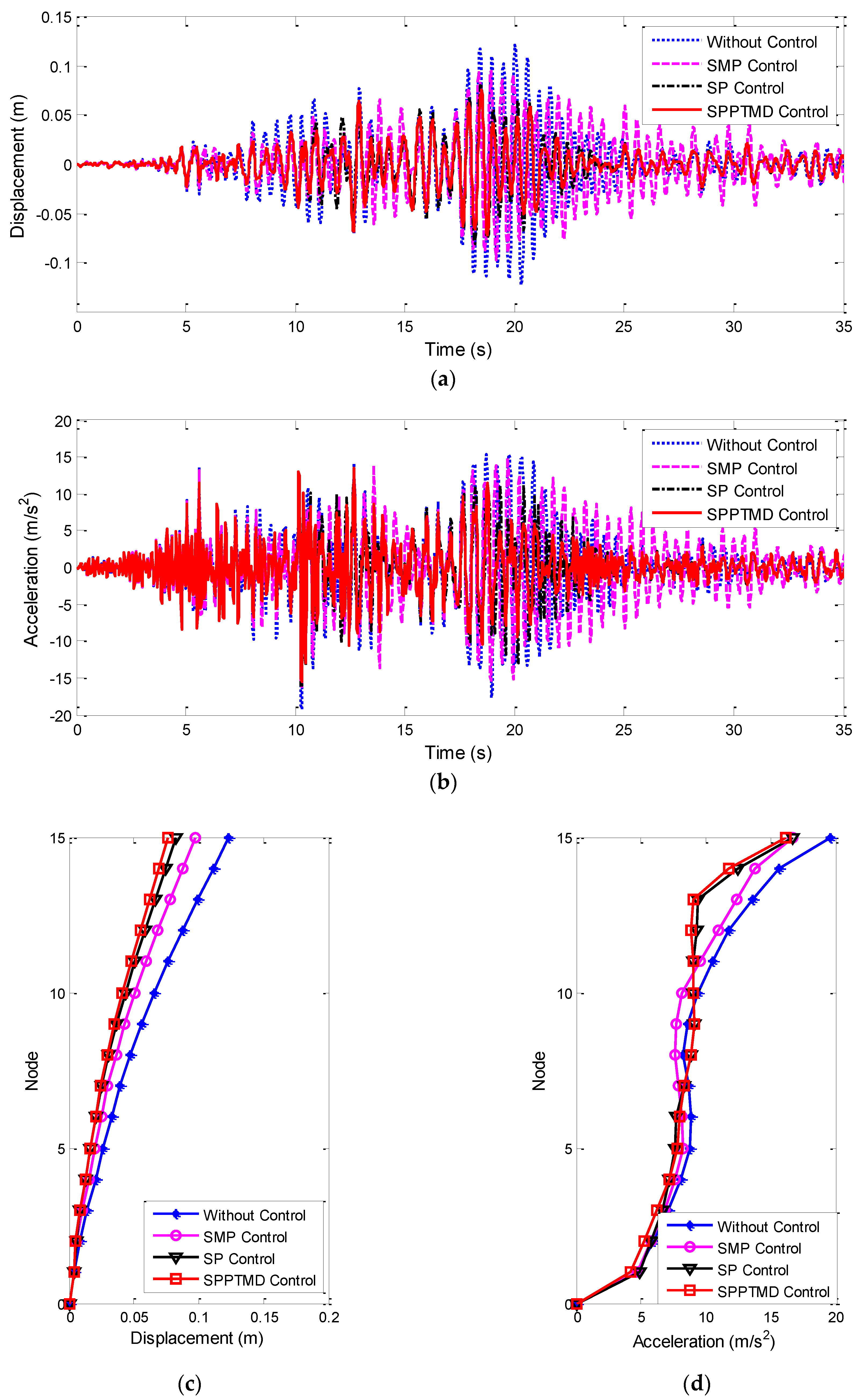
  • Vibration control performance of the proposed SPPTMD is slightly improved compared with the SP and SMP. The maximum displacements of the tower are reduced by SMP, SP and SPPTMD by 19.5%, 27.9% and 37.5%, respectively. For the RMS value of the displacement, reduction ratios are 12.3%, 39.4% and 45.2%, also demonstrating the superiority of the SPPTMD.
  • Vibration reduction ratio of the relative displacement is larger than that of the acceleration. The reduction ratio of the peak value and RMS value of the displacement is 37.5% and 45.2%, respectively. However, reduction ratio of the peak acceleration and RMS acceleration is only 22.8% and 41.3%.
  • In the parametric study, the pounding stiffness has little influence on the damping effect. When the pounding stiffness is increased by 10 times, the displacement vibration reduction ratio at the maximum pounding stiffness is only 6.9% higher than that of the minimum pounding stiffness.
  • Larger vibration reduction ratio can be achieved by increasing the mass ratio of the SPPTMD. This is similar to the classical TMD or PTMD.
  • The damping effectiveness is influenced by the gap. The optimal gap is determined by the mass ratio. When the mass ratio increases from 1.5% to 3%, the maximum displacement reduction ratio increases from 31.88% to 60.57% and the optimal gap decreases from 8 cm to 4 cm.
  • Damping ratio of the primary structure also influences the vibration reduction ratio of the SPPTMD. As the structural damping ratio increased from 0.5% to 5%, the reduction ratio of displacement drops from 51.7% to 32.4%.

Author Contributions

All authors discussed and agreed upon the idea, and made scientific contributions. Conceptualization, P.Z. and H.-N.L.; methodology, Q.W.; software, Q.W.; validation, Q.W., H.-N.L. and P.Z.; formal analysis, Q.W.; investigation, P.Z.; resources, H.-N.L.; data curation, P.Z.; writing—Original draft preparation, Q.W.; writing—Review and editing, P.Z.; visualization, P.Z.; supervision, H.-N.L.; project administration, H.-N.L.; funding acquisition, H.-N.L. All authors have read and agreed to the published version of the manuscript.

Funding

The authors would like to sincerely thank the financial supports from the State Key Program of National Natural Science Foundation of China (51738007 and 51808092).

Conflicts of Interest

The authors declare no conflict of interest.

References

  1. Shinozuka, M. The Hanshin-Awaji earthquake of January 17, 1995 performance of lifelines. In Technical Report NCEER; US National Center for Earthquake Engineering Research (NCEER): Buffalo, NY, USA, 1995; Volume 95. [Google Scholar]
  2. Chou, J.-S.; Tu, W.-T. Failure analysis and risk management of a collapsed large wind turbine tower. Eng. Fail. Anal. 2011, 18, 295–313. [Google Scholar] [CrossRef]
  3. Repetto, M.P.; Solari, G. Wind-induced fatigue collapse of real slender structures. Eng. Struct. 2010, 32, 3888–3898. [Google Scholar] [CrossRef]
  4. Abdo, T.M.; Huzayyin, A.A.; Abdallah, A.A.; Adly, A.A. Characteristics and Analysis of an Eddy Current Shock Absorber Damper Using Finite Element Analysis. Actuators 2019, 8, 77. [Google Scholar] [CrossRef] [Green Version]
  5. Ao, W.K.; Reynolds, P. Evaluation of eddy current damper for vibration control of a frame structure. J. Phys. Commun. 2019, 3, 055013. [Google Scholar] [CrossRef]
  6. Ao, W.K.; Reynolds, P. Analytical and experimental study of eddy current damper for vibration suppression in a footbridge structure. In Dynamics of Civil Structures; Springer: Berlin/Heidelberg, Germany, 2017; Volume 2, pp. 131–138. [Google Scholar]
  7. Ao, W.K.; Reynolds, P. Optimal Analysis, Design and Testing of an Electromagnetic Damper with Resonantshunt Circuit for Vibration Control of a Civil Structure. In Proceedings of the 23rd International Congress of Sound and Vibration, Athens, Greece, 10–14 July 2016. [Google Scholar]
  8. Ao, W.K.; Reynolds, P. Analysis of H and H2 Optimal Design Scheme for an Electromagnetic Damper with Shunt Resonant Circuit. In Shock & Vibration, Aircraft/Aerospace, and Energy Harvesting; Springer: Berlin/Heidelberg, Germany, 2015; Volume 9, pp. 201–212. [Google Scholar]
  9. Nyawako, D.S.; Reynolds, P. LQR controller for an in-service floor. In Dynamics of Civil Structures; Springer: Berlin/Heidelberg, Germany, 2011; Volume 4, pp. 227–237. [Google Scholar]
  10. Puma-Araujo, S.D.; Olvera-Trejo, D.; Martínez-Romero, O.; Urbikain, G.; Elías-Zúñiga, A.; Lacalle, L.N.L.D. Semi-Active Magnetorheological Damper Device for Chatter Mitigation during Milling of Thin-Floor Components. Appl. Sci. 2020, 10, 5313. [Google Scholar] [CrossRef]
  11. Kim, J.; Park, C.-S.; Min, K.-W. Fast vision-based wave height measurement for dynamic characterization of tuned liquid column dampers. Measurement 2016, 89, 189–196. [Google Scholar] [CrossRef]
  12. Gnanasambandham, C.; Fleissner, F.; Eberhard, P. Enhancing the dissipative properties of particle dampers using rigid obstacle-grids. J. Sound Vib. 2020, 484, 115522. [Google Scholar] [CrossRef]
  13. Lu, Z.; Liao, Y.; Huang, Z. Stochastic response control of particle dampers under random seismic excitation. J. Sound Vib. 2020, 481, 115439. [Google Scholar] [CrossRef]
  14. Tabatabai, H.; Mehrabi, A.B. TMD-Damped Stay Cable and Method and TMD. Google Patents US6292967B1, 25 September 2001. [Google Scholar]
  15. Battista, R.C.; Rodrigues, R.S.; Pfeil, M.S.; Aerodynamics, I. Dynamic behavior and stability of transmission line towers under wind forces. J. Wind Eng. 2003, 91, 1051–1067. [Google Scholar] [CrossRef]
  16. He, Y.; Lou, W.; Sun, B. Wind-induced vibration control of long span transmission tower with suspended mass pendulums. J. Zhejiang Univ. Eng. Sci. 2005, 39, 1891. [Google Scholar]
  17. Li, G.; Li, H.-N. Experimental study and application of metallic yielding–friction damper. J. Earthq. Tsunami 2013, 7, 1350012. [Google Scholar] [CrossRef]
  18. Batou, A.; Adhikari, S. Optimal parameters of viscoelastic tuned-mass dampers. J. Sound Vib. 2019, 445, 17–28. [Google Scholar] [CrossRef] [Green Version]
  19. Xu, Z.-S. Structure design, mathematical modeling and dynamical performance tests of a new viscoelastic elastomer damper. Measurement 2020, 108820. [Google Scholar] [CrossRef]
  20. Weber, F.; Boston, C.; Maślanka, M. An adaptive tuned mass damper based on the emulation of positive and negative stiffness with an MR damper. Smart Mater. Struct. 2010, 20, 015012. [Google Scholar] [CrossRef]
  21. Weber, F.; Maślanka, M. Frequency and damping adaptation of a TMD with controlled MR damper. Smart Mater. Struct. 2012, 21, 055011. [Google Scholar] [CrossRef]
  22. Bonello, P.; Brennan, M.J.; Elliott, S.J. Vibration control using an adaptive tuned vibration absorber with a variable curvature stiffness element. Smart Mater. Struct. 2005, 14, 1055. [Google Scholar] [CrossRef]
  23. Gsell, D.; Feltrin, G.; Motavalli, M. Adaptive tuned mass damper based on pre-stressable leaf-springs. J. Intell. Mater. Syst. Struct. 2007, 18, 845–851. [Google Scholar] [CrossRef]
  24. Heuss, O.; Salloum, R.; Mayer, D.; Melz, T. Tuning of a vibration absorber with shunted piezoelectric transducers. Arch. Appl. Mech. 2016, 86, 1715–1732. [Google Scholar] [CrossRef] [Green Version]
  25. Rustighi, E.; Brennan, M.; Mace, B. A shape memory alloy adaptive tuned vibration absorber: Design and implementation. Smart Mater. Struct. 2004, 14, 19. [Google Scholar] [CrossRef]
  26. Berardengo, M.; Della Porta, G.E.; Manzoni, S.; Vanali, M. A multi-modal adaptive tuned mass damper based on shape memory alloys. J. Intell. Mater. Syst. Struct. 2019, 30, 536–555. [Google Scholar] [CrossRef]
  27. Savi, M.A.; De Paula, A.S.; Lagoudas, D.C. Numerical investigation of an adaptive vibration absorber using shape memory alloys. J. Intell. Mater. Syst. Struct. 2011, 22, 67–80. [Google Scholar] [CrossRef]
  28. Tiwari, N.D.; Gogoi, A.; Hazra, B.; Wang, Q. A shape memory alloy-tuned mass damper inerter system for passive control of linked-SDOF structural systems under seismic excitation. J. Sound Vib. 2021, 494, 115893. [Google Scholar] [CrossRef]
  29. Tian, L.; Zhou, M.; Qiu, C.; Pan, H.; Rong, K. Seismic response control of transmission tower-line system using SMA-based TMD. Struct. Eng. Mech. 2020, 74, 129–143. [Google Scholar]
  30. Salvi, J.; Rizzi, E. Optimum tuning of Tuned Mass Dampers for frame structures under earthquake excitation. Struct. Control Health Monit. 2015, 22, 707–725. [Google Scholar] [CrossRef]
  31. Chen, J.; Lu, G.; Li, Y.; Wang, T.; Wang, W.; Song, G. Experimental study on robustness of an eddy current-tuned mass damper. Appl. Sci. 2017, 7, 895. [Google Scholar] [CrossRef] [Green Version]
  32. Elias, S.; Matsagar, V.; Datta, T.K. Along-wind response control of chimneys with distributed multiple tuned mass dampers. Struct. Control Health Monit. 2019, 26, e2275. [Google Scholar] [CrossRef] [Green Version]
  33. Zuo, L. Effective and robust vibration control using series multiple tuned-mass dampers. J. Vib. Acoust. 2009, 131, 031003. [Google Scholar] [CrossRef]
  34. Asami, T. Optimal design of double-mass dynamic vibration absorbers arranged in series or in parallel. J. Vib. Acoust. 2017, 139, 011015. [Google Scholar] [CrossRef]
  35. Asami, T.; Mizukawa, Y.; Ise, T. Optimal design of double-mass dynamic vibration absorbers minimizing the mobility transfer function. J. Vib. Acoust. 2018, 140, 061012. [Google Scholar] [CrossRef]
  36. Berardengo, M.; Høgsberg, J.; Manzoni, S.; Vanali, M.; Brandt, A.; Godi, T. LRLC-shunted piezoelectric vibration absorber. J. Sound Vib. 2020, 474, 115268. [Google Scholar] [CrossRef]
  37. Du, D.; Gu, X.; Chu, D.; Hua, H. Performance and parametric study of infinite-multiple TMDs for structures under ground acceleration by H∞ optimization. J. Sound Vib. 2007, 305, 843–853. [Google Scholar] [CrossRef]
  38. Li, H.-N.; Ni, X.-L. Optimization of non-uniformly distributed multiple tuned mass damper. J. Sound Vib. 2007, 308, 80–97. [Google Scholar] [CrossRef]
  39. Li, H.-N.; Liu, M.-M.; Fu, X. An innovative re-centering SMA-lead damper and its application to steel frame structures. Smart Mater. Struct. 2018, 27, 075029. [Google Scholar] [CrossRef]
  40. Li, K.; Darby, A.P. A buffered impact damper for multi-degree-of-freedom structural control. Earthq. Eng. Struct. Dyn. 2008, 37, 1491–1510. [Google Scholar] [CrossRef]
  41. Jiang, X.; McFarland, D.M.; Bergman, L.A.; Vakakis, A.F. Steady state passive nonlinear energy pumping in coupled oscillators: Theoretical and experimental results. Nonlinear Dyn. 2003, 33, 87–102. [Google Scholar] [CrossRef]
  42. Masri, S. Theory of the dynamic vibration neutralizer with motion-limiting stops. J. Appl. Mech. 1972, 39, 563–568. [Google Scholar] [CrossRef]
  43. Masri, S.F.; Caffrey, J.P. Response of Pounding Dynamic Vibration Neutralizer Under Harmonic and Random Excitation. J. Appl. Mech. 2019, 86, 021003. [Google Scholar] [CrossRef]
  44. Zhang, P.; Li, L.; Patil, D.; Singla, M.; Li, H.; Mo, Y.; Song, G. Parametric study of pounding tuned mass damper for subsea jumpers. Smart Mater. Struct. 2015, 25, 015028. [Google Scholar] [CrossRef]
  45. Zhang, P.; Ren, L.; Li, H.; Jia, Z.; Jiang, T. Control of wind-induced vibration of transmission tower-line system by using a spring pendulum. Math. Probl. Eng. 2015. [Google Scholar] [CrossRef] [Green Version]
  46. Carpineto, N.; Lacarbonara, W.; Vestroni, F. Hysteretic tuned mass dampers for structural vibration mitigation. J. Sound Vib. 2014, 333, 1302–1318. [Google Scholar] [CrossRef]
  47. Li, K.; Darby, A. An experimental investigation into the use of a buffered impact damper. J. Sound Vib. 2006, 291, 844–860. [Google Scholar] [CrossRef]
  48. Li, K.; Darby, A. Experiments on the effect of an impact damper on a multiple-degree-of-freedom system. J. Vib. Control 2006, 12, 445–464. [Google Scholar] [CrossRef]
  49. Li, H.; Zhang, P.; Song, G.; Patil, D.; Mo, Y. Robustness study of the pounding tuned mass damper for vibration control of subsea jumpers. Smart Mater. Struct. 2015, 24, 095001. [Google Scholar] [CrossRef]
  50. Zhang, P.; Song, G.; Li, H.-N.; Lin, Y.-X. Seismic control of power transmission tower using pounding TMD. J. Eng. Mech. 2012, 139, 1395–1406. [Google Scholar] [CrossRef]
  51. Lin, W.; Wang, Q.; Li, J.; Chen, S.; Qi, A. Shaking table test of pounding tuned mass damper (PTMD) on a frame structure under earthquake excitation. Comput. Concr. 2017, 20, 545–553. [Google Scholar]
  52. Zhao, N.; Lu, C.; Chen, M.; Luo, N.; Liu, C. Parametric Study of Pounding Tuned Mass Damper Based on Experiment of Vibration Control of a Traffic Signal Structure. J. Aerosp. Eng. 2018, 31, 04018108. [Google Scholar] [CrossRef]
  53. Yin, X.; Song, G.; Liu, Y. Vibration suppression of wind/traffic/bridge coupled system using multiple pounding tuned mass dampers (MPTMD). Sensors 2019, 19, 1133. [Google Scholar] [CrossRef] [Green Version]
  54. Yin, X.; Liu, Y.; Song, G.; Mo, Y. Suppression of bridge vibration induced by moving vehicles using pounding tuned mass dampers. J. Bridge Eng. 2018, 23, 04018047. [Google Scholar] [CrossRef]
  55. Wang, W.; Wang, X.; Hua, X.; Song, G.; Chen, Z. Vibration control of vortex-induced vibrations of a bridge deck by a single-side pounding tuned mass damper. Eng. Struct. 2018, 173, 61–75. [Google Scholar] [CrossRef]
  56. Song, G.; Zhang, P.; Li, L.; Singla, M.; Patil, D.; Li, H.; Mo, Y. Vibration control of a pipeline structure using pounding tuned mass damper. J. Eng. Mech. 2016, 142, 04016031. [Google Scholar] [CrossRef]
  57. Jiang, J.; Zhang, P.; Patil, D.; Li, H.N.; Song, G. Experimental studies on the effectiveness and robustness of a pounding tuned mass damper for vibration suppression of a submerged cylindrical pipe. Struct. Control Health Monit. 2017, 24, e2027. [Google Scholar] [CrossRef]
  58. Tan, J.; Ho, M.; Chun, S.; Zhang, P.; Jiang, J. Experimental Study on Vibration Control of Suspended Piping System by Single-Sided Pounding Tuned Mass Damper. Appl. Sci. 2019, 9, 285. [Google Scholar] [CrossRef] [Green Version]
  59. Li, S.; Sun, L.; Kong, F. Vibration Control Performance Analysis and Shake-Table Test of a Pounding Tuned Rotary Mass Damper under the Earthquake. Shock. Vib. 2019, 2019, 1–14. [Google Scholar] [CrossRef] [Green Version]
  60. Liu, M.; Yang, W.; Chen, W.; Li, H. Experimental investigation on multi-mode vortex-induced vibration control of stay cable installed with pounding tuned mass dampers. Smart Struct. Syst. 2019, 23, 579–587. [Google Scholar]
  61. Tan, J.; Jiang, J.; Liu, M.; Feng, Q.; Zhang, P.; Ho, S.C.M. Implementation of Shape Memory Alloy Sponge as Energy Dissipating Material on Pounding Tuned Mass Damper: An Experimental Investigation. Appl. Sci. 2019, 9, 1079. [Google Scholar] [CrossRef] [Green Version]
  62. Wang, W.; Hua, X.; Chen, Z.; Wang, X.; Song, G. Modeling, simulation, and validation of a pendulum-pounding tuned mass damper for vibration control. Struct. Control Health Monit. 2019, 26, e2326. [Google Scholar] [CrossRef]
  63. Collette, F.S. A combined tuned absorber and pendulum impact damper under random excitation. J. Sound Vib. 1998, 216, 199–213. [Google Scholar] [CrossRef]
  64. Wang, D. Analysis of vibration energy dissipation with vibro-impact absorber. J. Mech. Eng. 2014, 50, 87–92. [Google Scholar] [CrossRef]
  65. Lin, W.; Lin, Y.; Song, G.; Li, J. Multiple Pounding Tuned Mass Damper (MPTMD) control on benchmark tower subjected to earthquake excitations. Earthq. Struct. 2016, 11, 1123–1141. [Google Scholar] [CrossRef]
  66. Lin, W.; Song, G.; Chen, S. PTMD Control on a Benchmark TV Tower under Earthquake and Wind Load Excitations. Appl. Sci. 2017, 7, 425. [Google Scholar] [CrossRef]
  67. Fu, X.; Li, H.N.; Li, J.X.; Zhang, P. A pounding spacer damper and its application on transmission line subjected to fluctuating wind load. Struct. Control Health Monit. 2017, 24, e1950. [Google Scholar] [CrossRef]
  68. Tian, L.; Rong, K.; Bi, K.; Zhang, P. A Bidirectional Pounding Tuned Mass Damper and its Application to Transmission Tower-Line Systems under Seismic Excitations. Int. J. Struct. Stab. Dyn. 2019. [Google Scholar] [CrossRef]
  69. Wang, W.; Hua, X.; Wang, X.; Chen, Z.; Song, G. Numerical modeling and experimental study on a novel pounding tuned mass damper. J. Vib. Control 2018, 24, 4023–4036. [Google Scholar] [CrossRef]
  70. Ghasemi, M.R.; Shabakhty, N.; Enferadi, M.H. Vibration control of offshore jacket platforms through shape memory alloy pounding tuned mass damper (SMA-PTMD). Ocean Eng. 2019, 191, 106348. [Google Scholar] [CrossRef]
  71. Yang, Z.; Xia, Q.; Liu, S. The spring pendulum under different controlled parameters. Coll. Phys. 2011, 5, 23–26+42. [Google Scholar]
  72. Wang, J.; Liu, H.; Yuan, D.; Xu, Z. An improved state space model for parts of nonlinear oscillation systems and its numerical method. Chin. J. Appl. Mech. 2002, 112, 116–167. [Google Scholar] [CrossRef]
  73. Chandra, M. Spring Pendulum: A Nonlinear Paradigm. 2018. Available online: https://ssrn.com/abstract=3306010 or http://dx.doi.org/10.2139/ssrn.3306010 (accessed on 1 March 2019).
  74. DL/T. Technical Code for the Design of Tower and Pole Structures of Overhead Transmission Line; China Planning Press: Beijing, China, 2012. [Google Scholar]
  75. Saidi, I.; Gad, E.; Wilson, J.L.; Haritos, N. Development of passive viscoelastic damper to attenuate excessive floor vibrations. Eng. Struct. 2011, 33, 3317–3328. [Google Scholar] [CrossRef]
Figure 1. Locus of the suspended mass pendulum.
Actuators 10 00044 g001
Figure 2. Schematic of the spring pendulum (SP).
Actuators 10 00044 g002
Figure 3. Vibration modes of the SP. (a) Radial mode; (b) Swing mode.
Actuators 10 00044 g003
Figure 4. Locus of the SP.
Actuators 10 00044 g004
Figure 5. Spring pendulum pounding tuned mass damper (SPPTMD) system designed for controlling the vibration of a structure.
Actuators 10 00044 g005
Figure 6. Schematic of the structure-SPPTMD system.
Actuators 10 00044 g006
Figure 7. Controlling forces imposed on the ith degree of freedom (DOF).
Actuators 10 00044 g007
Figure 8. Schematic of the transmission tower.
Actuators 10 00044 g008
Figure 9. Layout of the SPPTMD on the transmission tower.
Actuators 10 00044 g009
Figure 10. Seismic response of the tower top under EQ1: (a) displacement; (b) acceleration; (c) envelope of displacement; and (d) envelope of acceleration.
Actuators 10 00044 g010
Figure 11. Seismic response of the tower top under EQ2: (a) displacement; (b) acceleration; (c) envelope of displacement; and (d) envelope of acceleration.
Actuators 10 00044 g011
Figure 12. Seismic response of the tower top under EQ3: (a) displacement; (b) acceleration; (c) envelope of displacement; and (d) envelope of acceleration.
Actuators 10 00044 g012
Figure 13. Displacement at the top of the tower with different pounding stiffness values.
Actuators 10 00044 g013
Figure 14. Displacement vibration reduction ratio of the tower with different mass ratios.
Actuators 10 00044 g014
Table 1. Seismic records.
IDEarthquakeEvent DateMagnitudeStation
EQ1Kobe16 January 19956.9Oka
EQ2Northridge17 January 19946.6Villa Park-Scrrano Avc
EQ3Kobe16 January 19956.9Takatori
Table 2. Vibration reduction ratios of the transmission tower.
EarthquakeDamper η d   ( % ) η a   ( % )
Peak (%)RMS (%)Peak (%)RMS (%)
EQ1With SPPTMD 43.355.015.4 41.9
With SP 32.9 48.4 15.3 34.7
With SMP26.724.77.714.8
EQ2With SPPTMD37.3 30.8 18.0 32.5
With SP29.8 27.4 15.3 29.9
With SMP21.37.015.70.8
EQ3With SPPTMD32.0 49.7 34.9 49.5
With SP20.942.4 25.4 41.6
With SMP10.45.214.00.02
AverageWith SPPTMD37.545.222.841.3
With SP27.939.418.735.4
With SMP19.512.312.55.2
Table 3. Vibration reduction ratios of the tower with different damping ratios.
Damping Ratio (%)Damper η d   ( % ) η a   ( % )
Peak (%)RMS (%)Peak (%)RMS (%)
0.5With SPPTMD control51.7 75.4 30.4 63.3
With SP control42.0 71.6 27.8 59.2
2With SPPTMD control43.3 55.0 15.4 41.9
With SP control32.9 48.4 15.3 34.7
5With SPPTMD control32.4 40.3 6.8 24.4
With SP control27.3 34.3 7.8 18.8
Publisher’s Note: MDPI stays neutral with regard to jurisdictional claims in published maps and institutional affiliations.

