Article

Design and Testing of a New Piezoelectric-Actuated Symmetric Compliant Microgripper †

Department of Electromechanical Engineering, Faculty of Science and Technology, University of Macau, Taipa, Macau, China
*
Author to whom correspondence should be addressed.
This paper is an extend version of our paper published in Lyu, Z.; Xu, Q. Design and Analysis of a Piezoelectric-Actuated Symmetric Compliant Microgripper. In Proceedings of the 2021 33rd Chinese Control and Decision Conference (CCDC), Kunming, China, 22–24 May 2021; pp. 3358–3368.
Actuators 2022, 11(3), 77; https://doi.org/10.3390/act11030077
Submission received: 9 February 2022 / Revised: 26 February 2022 / Accepted: 28 February 2022 / Published: 3 March 2022
(This article belongs to the Special Issue Design and Control of Compliant Manipulators: Volume II)

Abstract

:
Precise and stable operations in micromanipulation and microassembly require a high-performance microgripper. To improve the predominant static and dynamic characteristics, a novel piezoelectric-actuated compliant microgripper is designed, analyzed, and tested in this paper. The microgripper realizes a large gripping stroke by integrating a compliant bridge mechanism, an L-shaped mechanism, and a levered parallelogram mechanism. Optimization technology based on response surface analysis is applied to demonstrate the influence of structural parameters on the microgripper performance. Simulation results of finite element analysis reveal the superior performance of the designed microgripper in terms of gripping displacement, mechanism stiffness, equivalent stress, and natural frequency. A gripper prototype has been fabricated, and experimental studies have been conducted to test the microgripper’s physical properties. Experimental results show that the microgripper can grasp micro-objects with a maximum jaw motion stroke of 312.8 μ m, natural frequency of 786 Hz, motion resolution of ±0.6 μ m, and force resolution of ±1.69 mN. The gripping tests of an optical fiber with a diameter of 200 μ m and a metal sheet with a thickness of 100 μ m have been performed to demonstrate its gripping capability with position and force control.

1. Introduction

Micro/nano-manipulation robots are a significant application of robotic automation technology at the micro/nano meter scale. Such robots are extensively used in biomedical engineering, precision engineering, and advanced optics to complete micromanipulation and microassembly tasks [1]. As a micromanipulation end-effector, the microgripper plays a crucial role in grasping and releasing objects [2]. Various types of actuators, e.g., electrostatic, electrothermal, electromagnetic, piezoelectric, and shape memory alloy (SMA) [3,4], have been introduced for microgrippers. The piezoelectric-actuated microgripper has been widely studied and adopted owing to its small footprint size, high displacement resolution, fast response speed, and large output force. The compliant mechanism is typically used as a displacement amplification and transmission mechanism between the piezoelectric actuator (PEA) and the microgripper jaw by virtue of being free of friction, free of lubrication, vacuum compatibility, and ultrahigh-resolution of motion [5,6].
As PEA’s output displacement is extremely short (about 0.1% of PEA length), a popular design goal of the piezoelectric-actuated microgripper is to achieve a large gripping range. When the jaw gap is determined, a large gripping stroke can improve the clamp’s adaptability to grasp the targets of different sizes. To obtain a large gripping stroke, researchers have applied different types of compliant amplification mechanisms to design micromanipulators, such as lever mechanisms and bridge mechanisms [7,8,9]. In addition, high natural frequency is another goal to be pursued by the microgripper. A high natural frequency is capable of broadening control bandwidth to promote the performance of the control system [10]. Meanwhile, the high-frequency vibration of a gripper is helpful to overcome the adhesion between the cells and jaws in biological field [11]. Hence, a practical microgripper demands a large gripping stroke and a high natural frequency at the same time.
Previous studies have introduced plentiful types of compliant microgrippers based on the piezoelectric actuator [12,13,14,15,16,17,18,19,20,21,22,23,24,25,26,27,28]. For example, the pseudo-rigid-body model (PRBM) and finite element analysis (FEA) techniques were combined to develop multiple microgrippers with a gripping range of about 100 μ m in [14]. To expand the gripping range, the lever mechanism, Scott–Russell (SR) mechanism, and parallelogram mechanism were integrated into a gripper design for generating a gripping stroke of 1000 μ m [15]. Furthermore, the SR mechanism was improved in [16] to obtain a large displacement magnification. The gripping stroke of the designed microgripper is over 720 μ m. However, a common shortcoming of the aforementioned microgrippers is the relatively low natural frequency (i.e., 70 Hz and 70.7 Hz, respectively) and massive structure. Later, the lever, bridge, and parallelogram mechanisms were integrated in a symmetrical microgripper, which obtained a natural frequency of 1044 Hz [17]. Such a value of natural frequency is much higher than those of the previously designed microgrippers. However, the gripping displacement of the microgripper is only 93.52 μ m. Another microgripper was presented in [18] with a resonant frequency of 854 Hz and a gripping range of 184.04 μ m. Up to now, few piezoelectric-actuated microgrippers with the above two merits have been reported. It is necessary to design a piezoelectric-actuated microgripper with a large gripping range and high natural frequency to satisfy the increasing demands of applications.
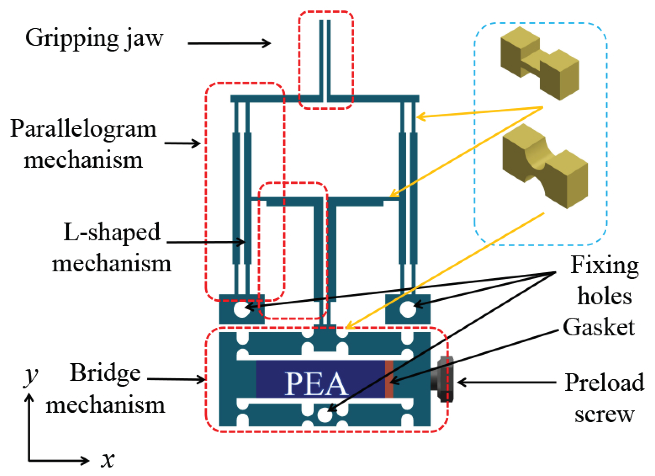
The main contribution of this paper is the design of a new piezoelectric-actuated microgripper dedicated to micromanipulation application. As compared with previous work, it is characterized by a large gripping stroke and high natural frequency for achieving high-speed manipulation of micro-objects. The microgripper consists of a piezoelectric actuator, a three-stage compliant amplification and guiding mechanism, and two jaws. The computational simulations based on response surface analysis and finite element analysis have been carried out to determine the vital structural parameters and to verify the working performance. The gripping stroke, gripping force, natural frequency, tracking ability, and motion resolution of the microgripper were tested by open-loop and closed-loop experiments. The gripping experiments on metal micro-wire and micro-shim further demonstrated its gripping ability.
The following sections of the paper are organized as follows. The mechanism design and analytical modeling of the microgripper are presented in Section 2. Response surface analysis and simulation study with FEA are conducted in Section 3. Prototype fabrication and open-loop experimental results are given in Section 4. An experimental study with closed-loop position/force control is performed in Section 5 along with performance discussion. Section 6 concludes this paper.

2. Mechanism Design and Modeling

This section introduces the compliant mechanism design and modeling of the proposed piezoelectric-actuated microgripper.

2.1. Mechanism Design

A computer-aided-design (CAD) model of the designed piezoelectric-actuated microgripper based on the compliant mechanism is shown in Figure 1. The symmetrical structure design can balance the internal stress of the gripper while increasing the displacement magnification ratio. A PEA is embedded in the bridge mechanism to provide the actuation force and displacement on both sides in the horizontal direction. The designed compliant microgripper mechanism includes bridge mechanisms, L-shaped mechanisms, and levered parallelogram mechanisms. The bridge mechanism is placed at the bottom of the gripper due to its compact mechanism, high rigidity, and sufficient output force. It can convert the double-ended horizontal displacement output into a vertical downward motion. One end of the L-shaped mechanism is connected to the bridge mechanism’s output end, and the other end pulls the parallelogram mechanism for generating a horizontal movement. A parallelogram mechanism pulled by an L-shaped mechanism functions as a lever providing parallel movement.
The gripping jaws perform gripping and releasing operations with the pushing or pulling movement of the parallelogram mechanism. The bridge mechanism uses the double-notch right circular shape of a compliant hinge owing to its merits of high precision and compact structure. The L-shaped mechanism and the parallelogram structure adopt rectangular compliant hinges with the characteristics of having a simple structure, having convenient processing, and being suitable for unidirectional bending. The three fixing holes on the microgripper are reserved for connecting with another device of the micromanipulation system. Gaskets and pre-tightening screws are employed in one end of the bridge mechanism to facilitate PEA installation. The pre-tightening screws can adjust the initial gap of the gripping jaws to clamp small targets of different sizes.

2.2. Modeling of the Mechanism

The microgripper’s displacement amplification performance is governed by the critical parameters of the compliant amplification and the guiding mechanism that undergoes deformations. Considering the symmetrical structure, Figure 2 only indicates a half-side PRBM of the compliant microgripper. Using PRBM, it is assumed that the system’s elastic deformation only occurs at the compliant hinge. Thus, the compliant hinges are replaced by rigid linkages with rotation joints. Some critical geometric parameters that will be used later are also marked in Figure 2. In addition, Figure 3 displays the motion vector diagram and mechanism deformation diagram of the half PRBM of the clamp. According to the velocity instantaneous center method, the following relationship can be obtained based on basic knowledge of mechanics of materials by referring to Figure 3a:
v C = ω 1 × l 1
v D = ω 1 × l 2
v E = v D = ω 2 × l 3
v F = ω 2 × l 4 = ω 3 × l 5
v I = ω 3 × l 6
where ω 1 , ω 2 , and ω 3 are the instantaneous angular velocities of linkages CD, O 2 E, and GI, respectively. R m is defined as the displacement amplification ratio of the proposed microgripper. It is expressed as the ratio between the gripping jaw’s output displacement and the gripper’s input displacement. Obviously, the magnification R m could be derived from the ratio of v I and v C at the same time. Considering that the compliant bridge amplifier mechanism has a double-ended input, one has
R m = v I v C = l 2 l 1 l 4 l 3 l 6 l 5 .
It can be seen that the displacement magnification of the gripper is only linearly related to some specific structural parameters.
When the bridge mechanism is actuated and displaced, the entire clamp will be slightly deformed. The calculation results of the rotation angles at different hinges are as follows:
φ A = φ B = φ C = φ D = θ 1 = l 2 x i n 2 l 1 l 1 2 + l 2 2
φ E = φ F = θ 2 = l 2 x i n l 1 l 3
φ G = φ H = φ I = φ J = θ 3 = l 2 l 4 x i n l 1 l 3 l 5
where θ 1 , θ 2 , and θ 3 are the deflection angle increment of linkages CD, EO1, and GI, respectively. For the microgripper, the work done by the external force can be expressed as
W = 1 2 F i n x i n
where F i n and x i n represent the input force and input displacement of the clamp.
Ignoring the influence of gravity, the potential energy of the microgripper is
E p = 1 2 i = A J K r i φ i 2 .
Furthermore, E p can be derived as
E p = K r A l 2 2 x i n 2 2 ( l 1 2 + l 2 2 ) l 1 2 + K r E l 2 2 x i n 2 ( 1 + η F ) 2 l 1 2 l 3 2 + 2 K r E η G x i n 2 ( l 2 l 4 l 1 l 3 l 5 ) 2
where K r A is the rotational stiffness of hinge A, K r E is the rotational stiffness of hinge E, and η F and η G are the stiffness ratios between hinge F and G to hinge G, respectively. The rotational stiffness of the right circular flexure hinge and short rectangular hinge can be estimated and expressed as
K r i = 2 E b t t i 5 2 9 π r i 1 2 , ( i = A , B , C , D )
K r i = E b t t i 3 12 l i , ( i = E , F , , J )
where E represents the elastic modulus, and t i , b t , l i , and r i are the width, thickness, length, and radius of the hinge, respectively.
According to Equations (10)–(14), the stiffness K i n of the gripper can be obtained as follows:
K i n = K r A l 2 2 ( l 1 2 + l 2 2 ) l 1 2 + K r E l 2 2 ( 1 + η F ) l 1 2 l 3 2 + 4 K r E η G ( R m l 6 ) 2 .
The kinetic energy of the gripper is the sum of the rotating and translational components in the system, which is described as
E K = I A B ω 1 2 + 1 2 ( I E O + I F O ) ω 2 2 + I G I ω 3 2 + 1 2 ( m i n + R m 2 ) x i n ˙ 2 ,
where m i n is the quality of the input end, and I A B , I E O , I F O , and I G I represent rotational inertia of component AB, EO, FO, and GI, respectively.
Through the Lagrange equation, the following equation is obtained
M x i n ¨ + K x i n ˙ = F i n R m F o u t ,
where M and F are the equivalent mass and equivalent stiffness of the gripper, F i n is the input force, and F o u t is the reaction force on the jaw. Further, the expressions of M and K are as follows:
M = I A B l 2 2 2 l 1 2 ( l 1 2 + l 2 2 ) + ( I E O + I F O ) l 2 2 l 1 2 l 3 2 + 2 I G I ( R m l 6 ) 2 + m i n + R m 2 m o u t ,
K = K i n .
Therefore, the natural frequency of the microgripper can be expressed as
f = 1 2 π K M .

3. Computational Simulation Study

The displacement magnification and dynamic modal as derived above is not enough to reveal the complete performance of the gripper. In this section, the response surface analysis (RSA) and FEA based on computational techniques are conducted to evaluate the performance of the clamp mechanism. The analysis and simulation are carried out by means of ANSYS Workbench software.

3.1. Response Surface Analysis

The response surface method is adopted to simulate a real limit state surface by fitting a response surface through a series of deterministic tests. In essence, as a comprehensive analysis technique based on statistics, the response surface method is particularly suitable for dealing with the effect of several variables on the same system or structure. More information about the response surface method could refer to [29,30].
The physical meanings of the structural parameter arrays l 1 , l 2 , l 3 , l 4 , l 5 , l 6 and t 1 , t 2 , t 3 , t 4 , t 5 , t 6 are denoted in Figure 2. To optimize the structural parameters of the microgripper, the parameter array [ t 1 , t 2 , t 3 , t 4 , t 5 , t 6 ] is taken into account because other parameters l 1 , l 2 , l 3 , l 4 , l 5 , l 6 can be determined once the selected parameter array is given. The overall size of the microgripper is constrained within 54 mm × 28 mm × 5 mm. The compact structure design facilitates the integration of the gripper into a micromanipulation system for practical use. The radius R of the double-notch right circular hinges used in the bridge mechanism is assigned as 0.8 mm to achieve a large deformation. The thicknesses d 1 and d 2 are set as 0.5 mm in view of the limited manufacturing capacity.
To design a high-performance clamp, the maximization of the output displacement S of the unilateral gripping jaw and the natural frequency F of the system are selected as the optimization goals. The safety factor Q of the microgripper structure is limited to be greater than 1 to ensure that the material of the compliant hinge does not yield during the deformation process. The quantitative analysis for the sensitivity of the design parameters to the objective function is obtained through simulation calculation. The higher the absolute value of sensitivity, the greater the weight of its influence on the objective function. The sensitivity values for the parameter array t 1 , t 2 , t 3 , t 4 , t 5 , t 6 with respect to S are computed as 0.40 , 0.02 , 0.05 , 0.003 , 0.40 , 0.21 , as shown in Figure 4. It is found that t 1 , t 2 , and t 3 are the dominating factors affecting the output displacement S. The response surface between the structural parameters and maximum output displacement is shown in Figure 5. It indicates that S rises sharply with the increasing of t 3 and t 5 and decreases with the increasing of t 1 . Finally, according to the optimal design requirements, the key structural parameters of the microgripper are determined as shown in Table 1.

3.2. FEA Simulation Result

To evaluate the performance of the designed microgripper, FEA simulation study has been carried out. The Al-7075 alloy material is chosen owing to its low density, high elasticity, and suitable strength. The PEA actuator (model: RP150/55/20, from Harbin Soluble Core Technology Co., Ltd. (Harbin, China)) is selected as an actuator. It offers a nominal displacement of 20 μ m and a maximum blocking force of 900 N. In simulation study, the PEA is replaced by a spring of equal stiffness. By applying a force of 900 N at both ends of the bridge structure, the maximum unilateral input displacement is obtained as 8.6 μ m. The simulation result of the total deformation state of the microgripper is shown in Figure 6. It is seen that the maximum displacement of one jaw of the microgripper in the horizontal direction is up to 155.72 μ m. Due to the symmetrical double-jaw gripping, the whole gripping range of the microgripper is calculated as 311.44 μ m, which ensures the capability of grasping micro-objects.
Figure 7 shows the linear relationship between the output displacement and input displacement. It exhibits an amplification ratio of 16.72. Simulation result of equivalent (Von Mises) stress for the gripper mechanism indicates that the maximum stress occurs at the compliant hinge, especially the compliant hinge of the bridge structure’s upper part. The maximum Von Mises stress is 162.11 MPa, which is smaller than the tensile strength of the material. When the maximum actuation force (900 N) is applied, the gripper’s minimum safety factor is 3.53. Hence, the microgripper can provide the maximum gripping displacement without the yield phenomenon of the material.
In addition, the modal analysis results of the first three-order resonances for the microgripper are shown in Figure 8. In the first mode shape, the parallelogram mechanism, L-shaped mechanism, and bridge mechanism all rotate in the same direction relative to the fixed hole at 843 Hz. The second model represents the microgripper’s working state. The movement of the two gripping jaws in the horizontal direction likes the gripping motion of the microgripper. The natural frequency of this mode is 933 Hz. In the third mode, the microgripper’s jaws move out of the XY plane with the natural frequency of 1665 Hz. The modal analysis results verified that the microgripper could translate in the opening/closing direction. The lowest natural frequency of the microgripper indicates that the mechanism has favorable dynamic characteristics.

4. Prototype Fabrication and Experimental Tests

This section presents the prototype fabrication and experimental tests of the microgripper. The gripper performances in terms of output displacement, natural frequency, and gripping force were experimentally tested in experiments.

4.1. Prototype Fabrication and Experimental Setup

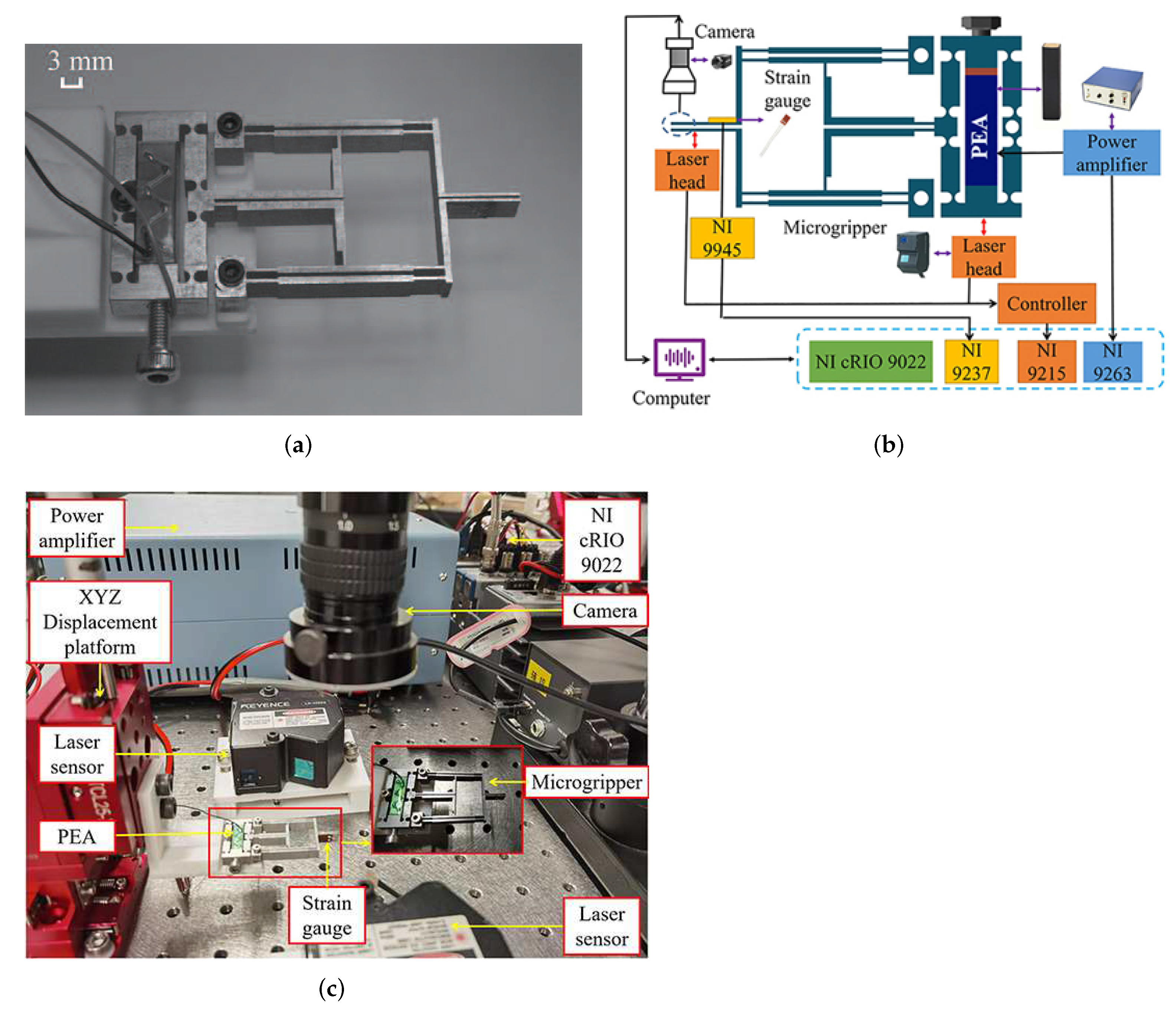
The wire electric-discharge machining (WEDM) technology was adopted to manufacture the designed gripper with the Al-7075 alloy material. The material has good performance with modular elasticity of 71 GPa, Poisson’s ratio of 0.33, density of 2810 kg/m 3 , and yield strength of 524 MPa. The fabricated microgripper is compact, as shown in Figure 9a. To verify the characteristics of the clamp, an experimental setup was constructed as shown in Figure 9b,c.
First, the microgripper was fixed onto an XYZ translational stage (model: HTML25-NS, from Hangzhou SPL Photonics Co., Ltd. (Hangzhou, China) via a connector to realize a three-axis precision movement. Two laser displacement sensors (model: LK-H055, from Keyence Corp. (Osaka, Japan) with a measurement range of ±10 mm were mounted on two sides of the gripper to measure the input end and output displacements, respectively. To measure the gripping force, a strain gauge (model: BFH 350-3AA, from Chengtec Electronics Ltd. (Shanghai, China)) with a sensitivity factor of 2.0 was pasted on the microgripper’s jaw side, and its output signal was conditioned by a quarter Wheatstone bridge circuit. A voltage amplifier (model: EPA-104, from Piezo Systems, Inc. (Cambridge, MA, USA)) was used to drive the PEA with a voltage range of 0–150 V. The industrial camera (model: TD-UV20S, from Sanqtid Co. (Shenzhen, China)) was installed above the microgripper’s jaws to observe and record the gripping process. The signal driving, data acquisition, and signal processing functions of the experimental system were realized by a real-time controller (model: NI cRIO 9022, from National Instruments Corp. (Austin, TX, USA)) with analog input and output modules. The entire experimental setup was mounted on a vibration isolation table (model: RS2000, from Newport Corp. (Irvine, CA, USA)).

4.2. Open-Loop Test of the Microgripper Displacement

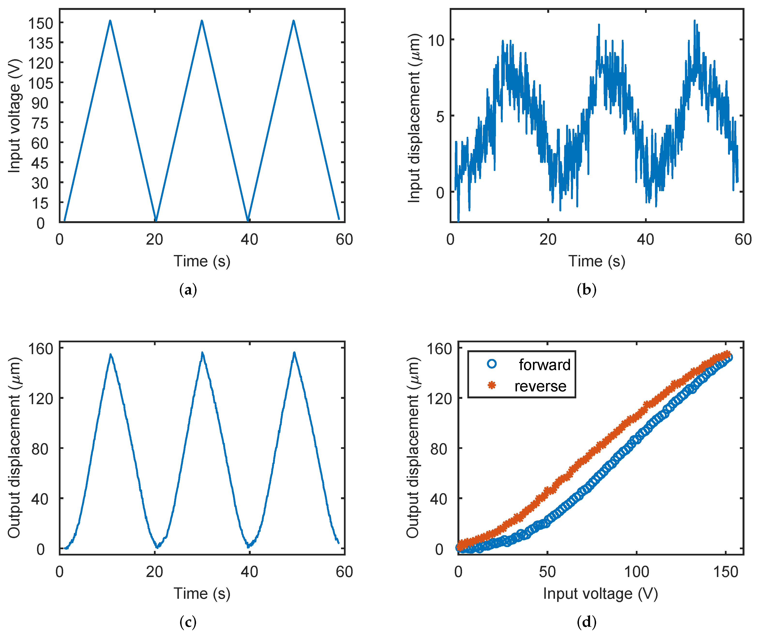
In the open-loop experiment of displacement test, the PEA’s driving voltage linearly increases and decreases in the range of 0–150 V. The experiments were repeated three times to examine the repeatability and hysteresis of the gripper.
The output voltage, input displacement, and output displacement of the gripper during the experiment are shown in Figure 10. It can be observed that when the input voltage is 150 V, the microgripper’s unilateral output displacement is about 156.4 μ m. Figure 10b shows that the input displacement signal contains relatively large noise due to the small ratio of the input displacement to the input voltage. The experimental result of the output displacement of two jaws is nearly 312.8 μ 
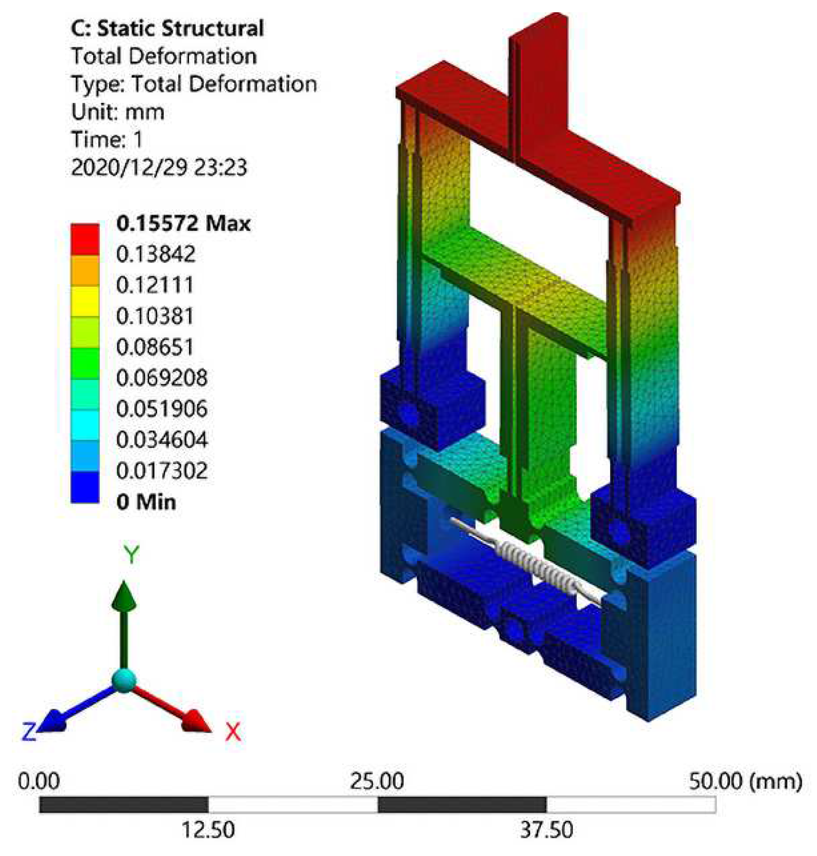
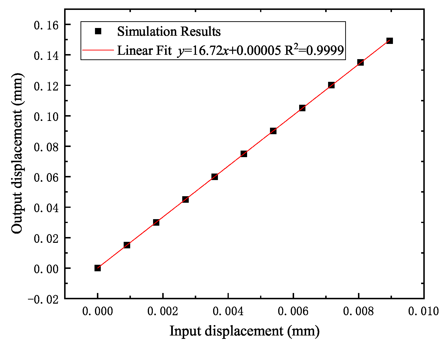
m with displacement amplification ratio of 15.64. Obviously, the experiment result is close to the FEA simulation result (16.72), and it demonstrates the effectiveness of the FEA simulation. The model result (21.02) is larger than the other two results. There are two reasons account for this phenomenon. First, the theoretical model supposes that the deformation only occurs in the compliant hinge, while part of rigid structure also contributes to the deformation and consumes the energy. Second, the thickness of the gripper was not considered in the theoretical model, and this will affect the deformation capacity of the mechanism. As for the discrepancy of experimental and simulation result, it may be caused by the machining error, assembly error, and measurement error. In addition, Figure 10d shows the hysteresis effect of the gripper due to the piezoelectric actuation. It causes a nonlinear relationship between the output displacement and input voltage, which requires a suitable control algorithm to achieve precise motion.

4.3. Open-Loop Test of the Natural Frequency

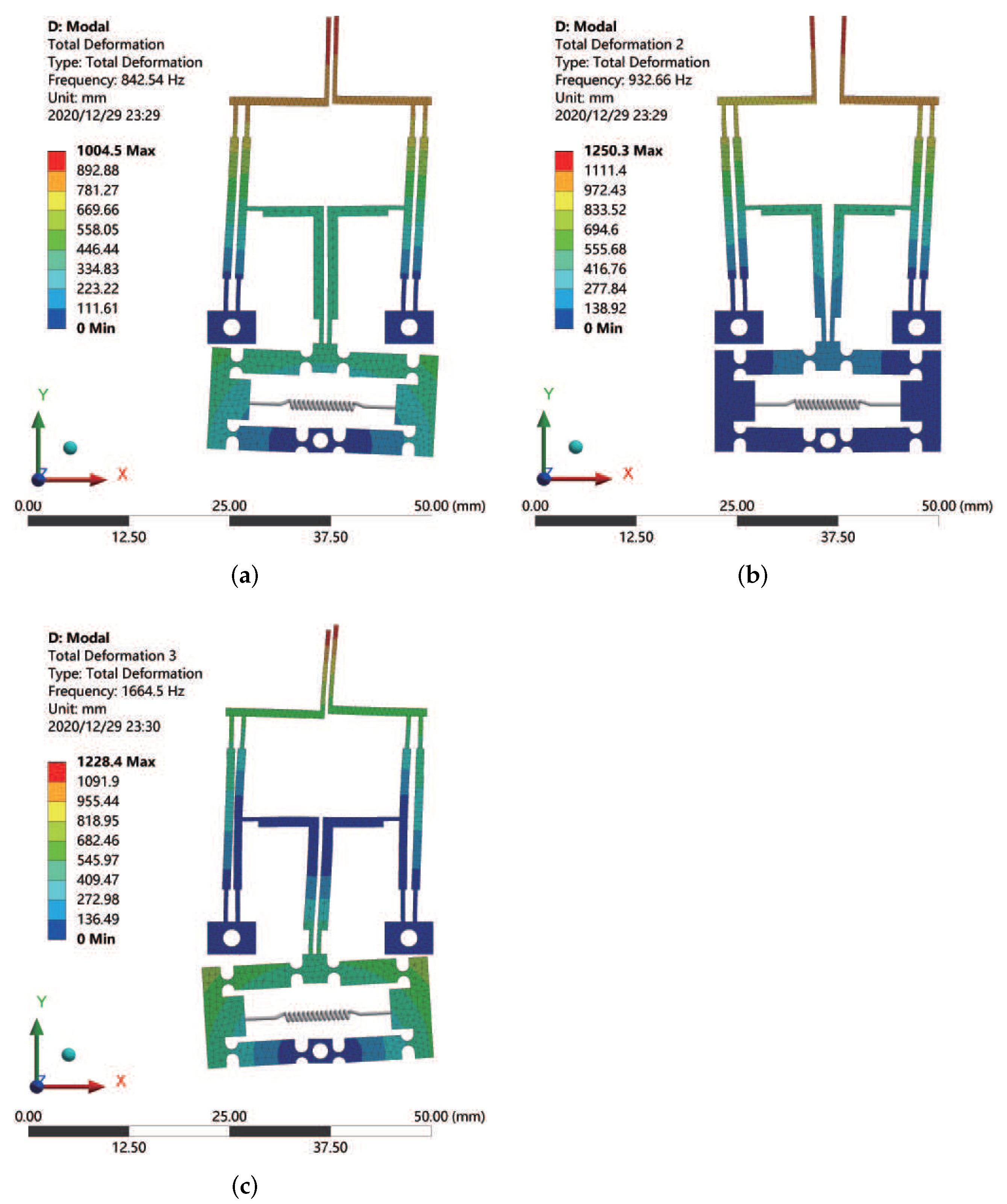
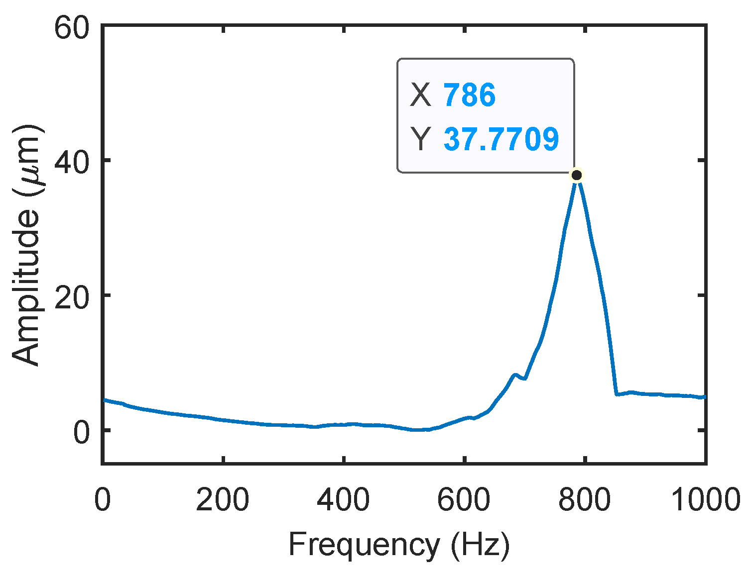
The dynamic analysis experiment of the gripper was carried out to identify the natural frequencies corresponding to the mode shapes of the clamp. A sinusoidal sweep signal was applied to PEA embedded in the microgripper to excite the system. The frequency range of sinusoidal sweep signals is 1 Hz to 1000 Hz, and the amplitude is 1 V. The sweep rate is 1 Hz/s, and the increment is 0.1 Hz. The NI cRIO 9022 operated in FPGA mode, and the sampling frequency was set to 3000 Hz. The laser displacement sensor is adopted to pick up the displacement signal at the jaw tip of the gripper.
The obtained frequency response is shown in Figure 11. It can be observed that the peak of amplitude is located at the frequency of 786 Hz. That is, the first natural frequency of the microgripper is 786 Hz. The experimental result is slightly lower than the simulation result (843 Hz) and theoretical analysis result (922 Hz). The discrepancy is mainly induced by the increased mass of PEA, bolts, and gaskets in practice, which is not considered in the simulation and model. According to the theoretical expression Equation (20), the introduced mass will increase the equivalent mass (M) and lead to the reduction of natural frequency (f).

4.4. Open-Loop Test of the Microgripper Force

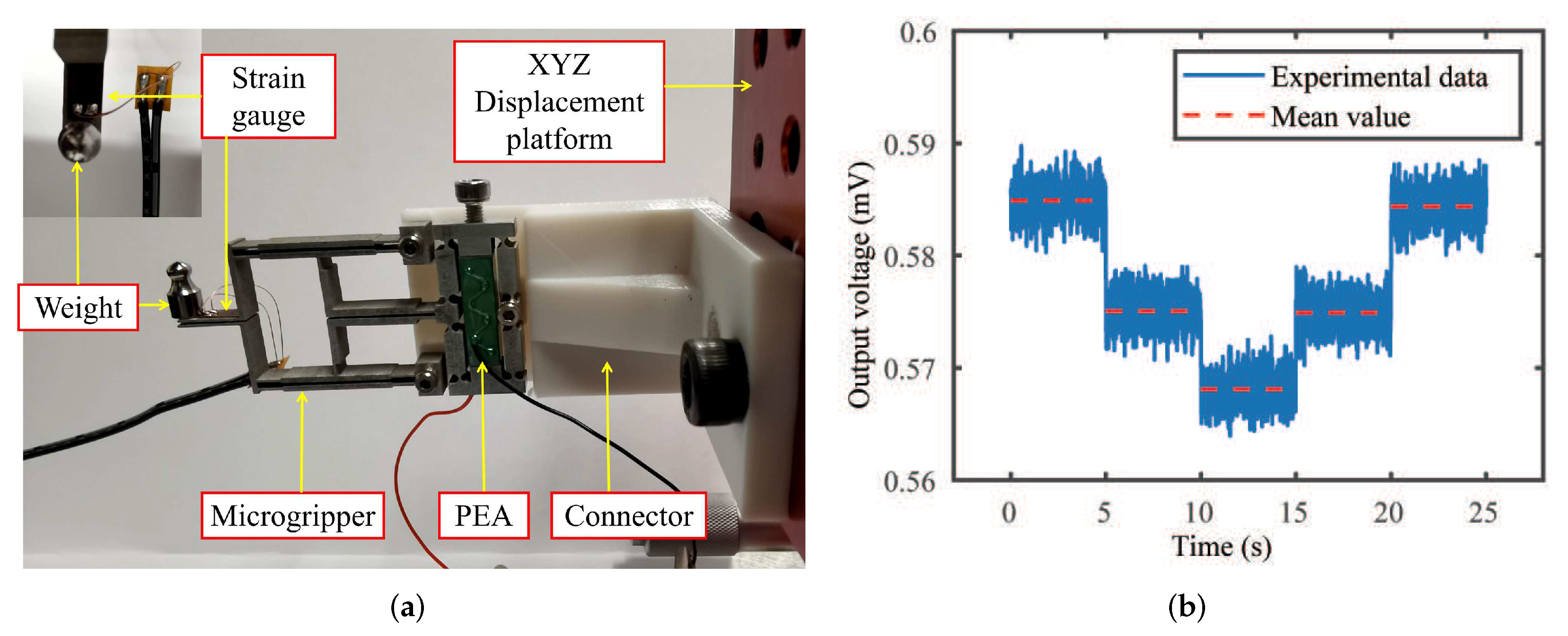
The strain-gauge force sensor was calibrated by gradually loading and unloading the gripper jaw with standard weights (1 g and 2 g), as shown in Figure 12a. Without a weight load, the output voltage of the sensor is 0.585 mV. The sensor output signal obtained by the calibration experiment is shown in Figure 12b. When the weight is loaded to elongate the strain gauge, the output voltage gradually decreases. The unloading process shows the opposite change tendency. The calibration result of the force-to-electricity conversion coefficient of the strain-gauge force sensor is obtained as −1185.2 mN/mV.
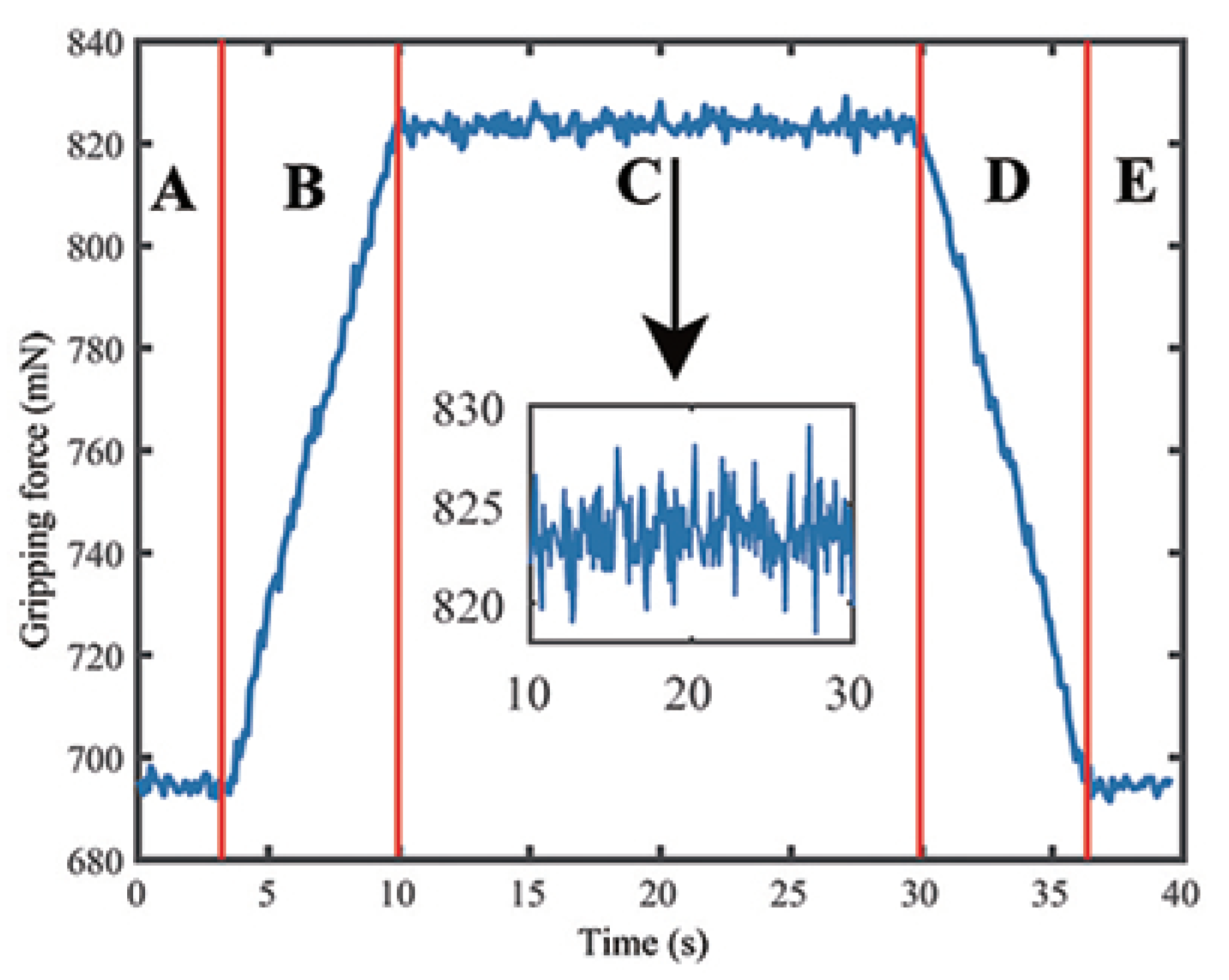
The gripping experiment is carried out using a metal micro-wire with the diameter of 350 μ m. The strain-gauge output voltage obtained in the gripping experiment is converted into force value, as shown in Figure 13. The gripping process is divided into five stages: A–B–C–D–E. In phases A and E, the microgripper does not contact the wire. Thus, the gripping force is close to 692.91 mN (zero offset). After entering phase B, the microgripper begins to contact the wire, and the gripping force increases with the input voltage. The situation in stage D is just the opposite process of releasing. Phase C corresponds to the stable gripping phase when the input voltage is held on. It is observed that the gripping force at this time is about 823.71 mN, which means that the maximum relative gripping force during the whole process is 130.80 mN. The measured tendency of gripping force is consistent with the FEA simulation and conforms to the predicted laws of physics. The force sensor noise is shown in the inset of Figure 13, which indicates a two-standard deviation (2 σ ) of 1.69 mN. That is, 95% of force sensor signals lie within the range of 130.80 ± 1.69 mN. Hence, the resolution of the force sensor is about ±1.69 mN.

5. Experimental Results of the Microgripper with Closed-Loop Control

Due to the presence of nonlinearity such as the hysteresis effect, it is necessary to implement a closed-loop control for achieving precision motion tracking of the gripper jaws. In this work, the proportional-integral (PI) control strategy was applied for the demonstration of closed-loop control to realize precise motion control of the microgripper.
When there is only proportional control, the system output exhibits a steady-state error. To eliminate the steady-state error, an integral control term is introduced in the controller. Thus, the PI controller can eliminate the system’s steady-state error after its response enters the steady state. The control action of the PI controller is described as follows.
u ( t ) = K P e ( t ) + 1 T I 0 t e ( t ) d t
where K P is the proportionality coefficient, T I is the integration time constant, e ( t ) is the error input, and u ( t ) is the output signal of the controller. The parameters of the PI controller ( K P = 35 and K I = 0.00005) were tuned by trial-and-error for generating satisfactory tracking results. The data acquisition frequency of the closed-loop control system was set as 1 kHz.

5.1. Experimental Results of Motion Tracking

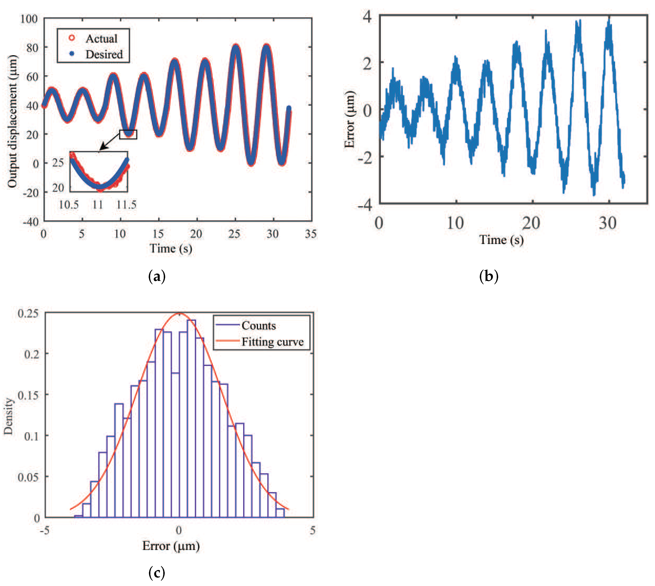
First, the sinusoidal motion trajectories of different amplitudes at a frequency of 0.25 Hz were used to test the microgripper performance. The signal of each amplitude was continuously driven for two cycles. The experimental results of position tracking and tracking errors are shown in Figure 14. The maximum errors are obtained as 1.38 μ m, 2.16 μ m, 2.88 μ m, and 3.81 μ m, corresponding to the overall amplitudes of 20 μ m, 40 μ m, 60 μ m, and 80 μ m, respectively. The errors are 6.9%, 5.4%, 4.6%, and 4.7% of the maximum amplitudes of the corresponding output displacements, respectively. The error data obtained from the experiment meet the normal distribution condition with 2 σ of 2.54 μ m, i.e., 95% confidence interval for the error locating in ±2.54 μ m.
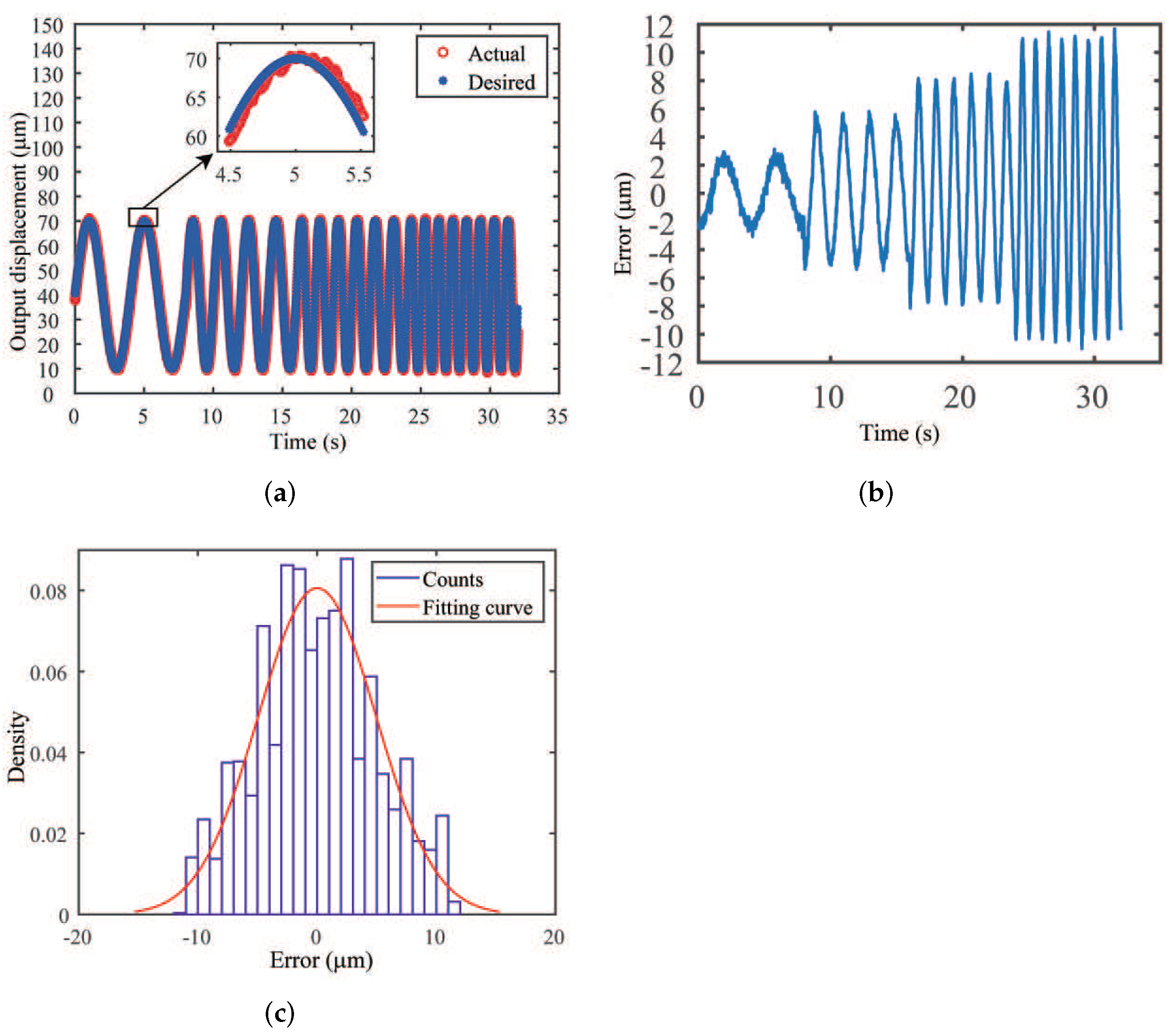
Second, experimental studies were conducted by varying the frequency of the sinusoidal trajectory with the amplitude of 60 μ m. The results are shown in Figure 15. It is seen that the maximum tracking errors are 2.81 μ m, 5.61 μ m, 8.07 μ m, and 11.06 μ m for the corresponding frequencies of 0.25 Hz, 0.5 Hz, 0.75 Hz, and 1 Hz, respectively. The percentage maximum tracking errors with respect to the amplitude of the reference input are 4.6%, 9.3%, 13.4%, and 19.3%, respectively. Similarly, the error signal in the whole process follows a normal distribution with 95% confidence interval of ±9.88 μ m.
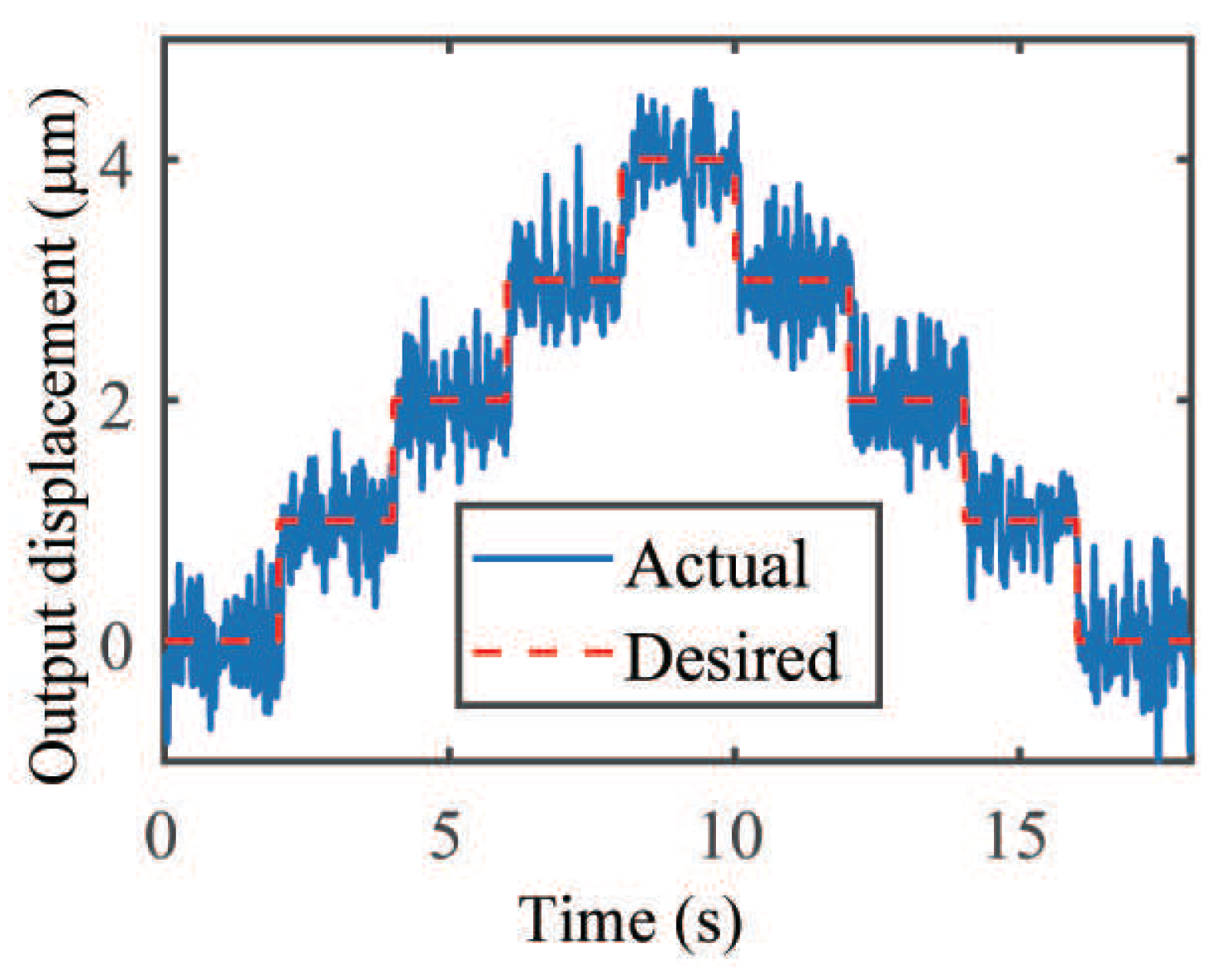
Third, to verify the motion resolution of the microgripper, step response experiments were performed. A stair signal with a constant time of 2 s and amplitude of 1 μ m for each step was used. The reference input signal and tracking results are presented in Figure 16. The fluctuation of the experimental data is caused by the noise of the adopted laser displacement sensor with 2 σ = 0.5978 μ m. That is, 95% of sensor readings lie within the range of about ±0.6 μ m. Thus, the experimental results reveal that the closed-loop motion resolution of the microgripper is about ±0.6 μ m. The experimental results confirm the satisfactory performance of the developed microgripper with PI control algorithm.

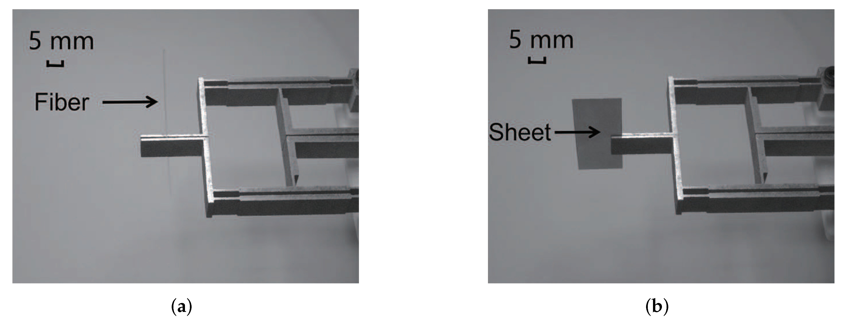
5.2. Experimental Results of Gripping Test

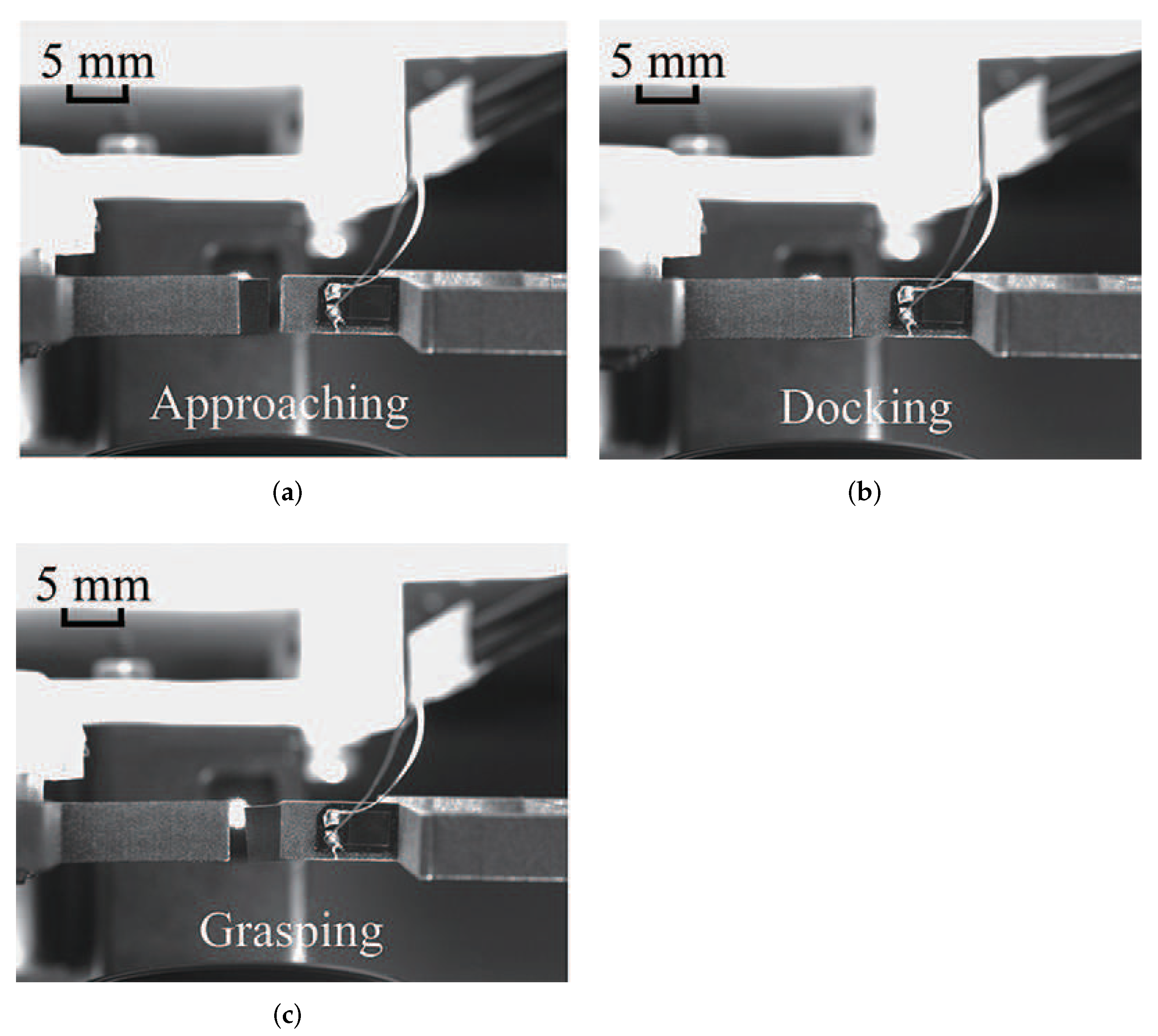
To demonstrate the gripping capability of the designed gripper, the gripping experiment was carried out using an optical fiber with a diameter of 200 μ m and a metal sheet with a thickness of 100 μ m. The snapshots of clamping states are shown in Figure 17.
Moreover, the gripping performance is also demonstrated by the docking gripping for a square shim with the thickness of 200 μ m. The docking process is shown in Figure 18. Two microgrippers were used in the docking experiment. First, the left gripper clamped the shim and approached to the right. Then, alignment was achieved by manually adjusting the gap between the two grippers. Next, the right gripper was driven to clamp the shim. At this moment, the left gripper released the clamp jaw and drew back to the left. Finally, the shim was successfully held in the air by the right gripper, i.e., the designed gripper in this work. The proposed microgripper exhibits a reliable working ability to adapt to physical micromanipulation tasks.
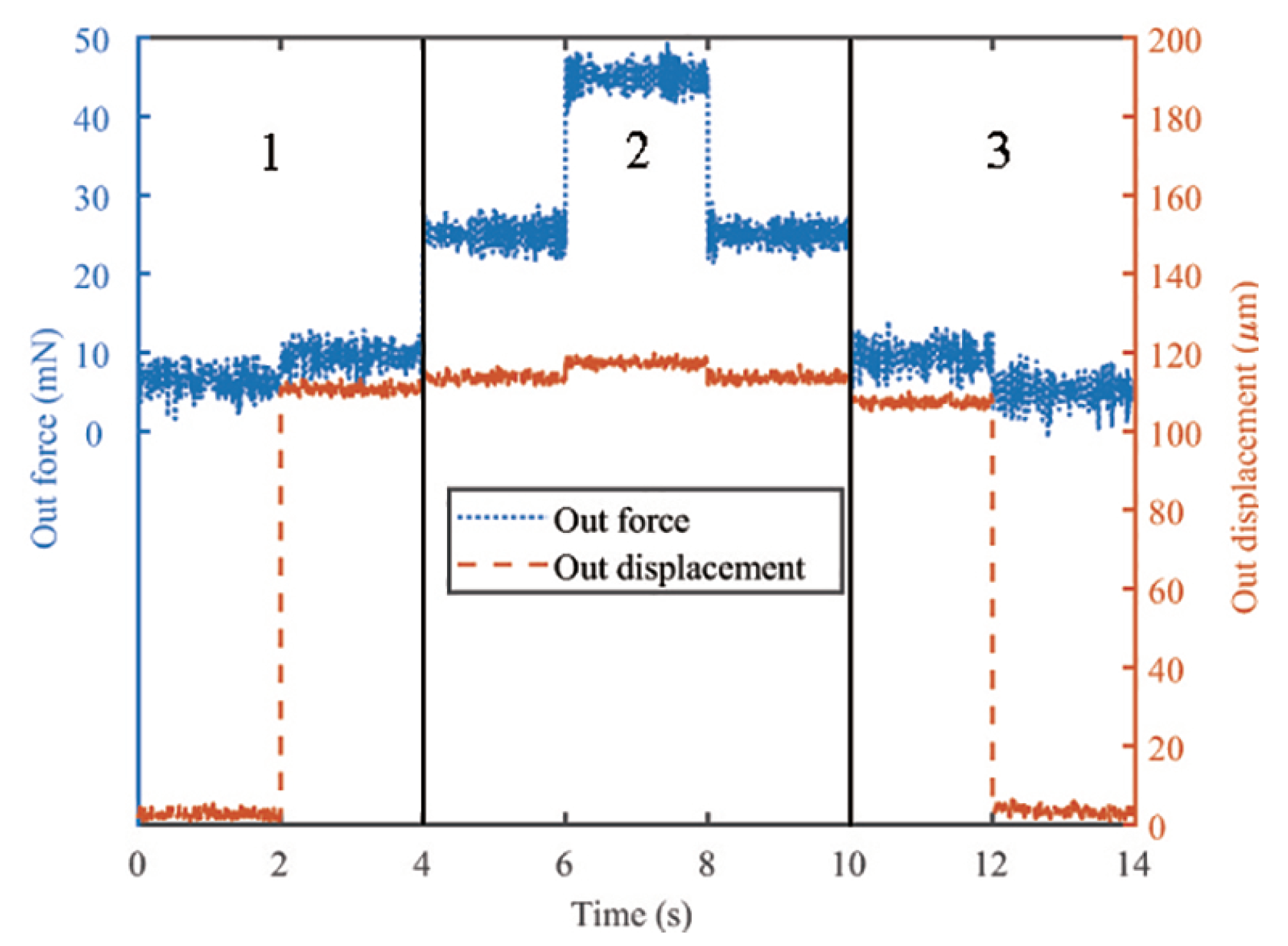
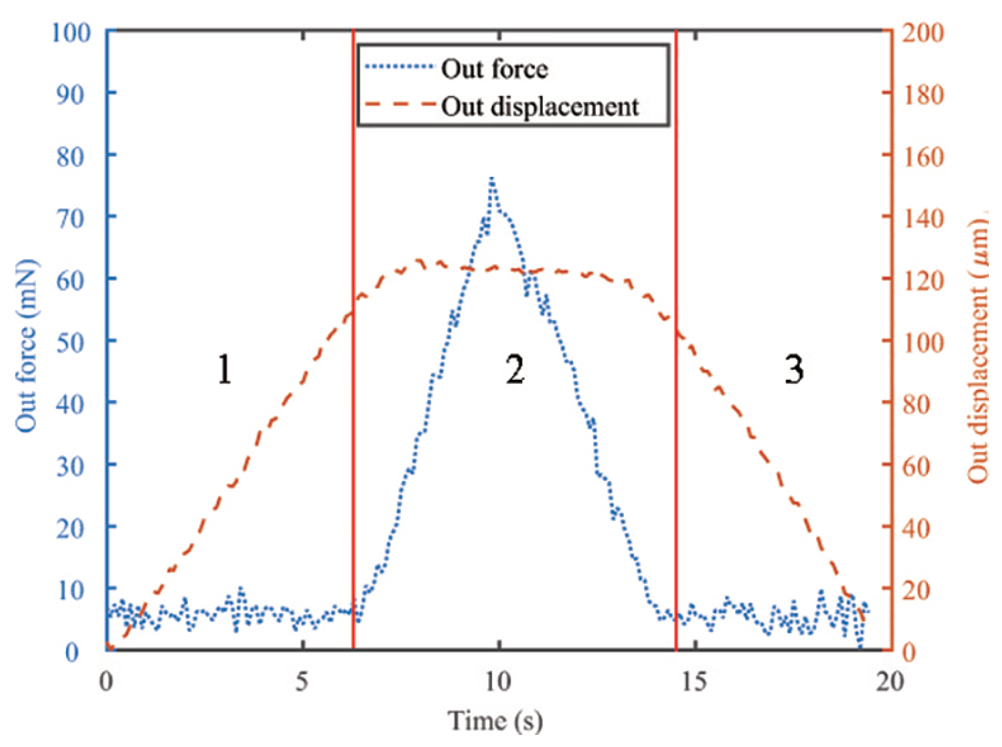
As the micro-object is easily damaged, it is necessary to control the gripping force during the operational process. In this work, a case study of micro-wire gripping is demonstrated to realize the non-destructive precision gripping by utilizing the position/force switch control strategy. First, position control is implemented when the gripping jaws approach the wire. After contact, the force control comes up while the position control is closed. Before using the hybrid control strategy, an open-loop control experiment of a full-scale driving voltage is helpful to find valuable information about the gripping displacement and force. Figure 19 shows the displacement and force signals during the open-loop test for gripping a micro-wire with the diameter of 350 μ m. The dotted curve represents the gripping force signal, and the dashed curve denotes the jaw displacement signal. According to different gripping processes, Figure 19 is divided into three segments. The displacement changes sharply while the gripping force is nearly unchanged during segment 1 and segment 3. However, the curve of segment 2 presents the opposite phenomenon. The dividing points between different segments can be easily observed, which are used in the control experiments. The testing result of the closed-loop gripping experiment with position/force switch control is shown in Figure 20. Similarly, Figure 20 is also divided into three segments according to the difference in the control variable. Segment 1 and segment 3 correspond to the position control stage, which realizes the grasp and release of the metal wire via the step position signal. It is observed that the gripping position and force were effectively controlled based on the PI control strategy.

5.3. Performance Comparison

To further evaluate the performance of the fabricated microgripper, it is necessary to compare the proposed microgripper with previous designs of piezoelectric-actuated gripper in the literature. The main performances, including the displacement magnification ratio, gripping stroke, and natural frequency of typical grippers, are shown in Table 2. They indicate that the proposed microgripper has the advantages of large gripping stroke and high natural frequency among these designs. To highlight the overall advantages of the gripper, a new parameter is defined. The new parameter is the product of working stroke and resonant frequency. It takes into account the working stroke and resonant frequency of the gripper. The higher its value is, the stronger the comprehensive ability of the gripper is. In the last column of Table 2, the proposed gripper exhibits the largest parameter value. Therefore, the designed microgripper has superior comprehensive performance.
By examining the relationship between the first two sets of data (amplification ratio and gripping stroke), it can be concluded that the magnification ratio is not directly proportional to the gripping stroke. This is the reason why the gripping stroke rather than magnification is adopted as the design objective for the gripper.

6. Conclusions

The paper proposed a new compliant microgripper driven by a piezoelectric actuator dedicated to micromanipulation and microassembly tasks. The gripper is composed of a PEA and a three-stage flexible amplification mechanism to realize the large-stroke parallel gripping of the two jaws. A mathematical model was established to analyze the displacement amplification capability of the gripper. The sensitive structure parameters of the clamp were determined via response surface analysis. The finite element analysis results based on computer simulation demonstrated the gripper’s satisfactory characteristics of gripping stroke and natural frequency. The proposed microgripper was fabricated and tested by extensive experimental studies. The open-loop test experiments showed that the gripper’s gripping stroke is 311.44 μ m, and the first natural frequency was measured at 786 Hz. The closed-loop experiments based on the PI control strategy exhibited the microgripper’s tracking ability on the sinusoidal reference signal and the resolution ability of ±0.6 μ m from the step response test. The gripping experiments on an optical fiber with a diameter of 200 μ m and a metal sheet with a thickness of 100 μ m have demonstrated the clamp’s gripping capability. Future work will focus on advanced position/force control of the microgripper to achieve delicate micromanipulation of more micro-objects, such as metal wire and optical fiber.

Author Contributions

Conceptualization, Z.L., Q.X.; methodology, Z.L., Q.X.; software, Z.L.; validation, Z.L.; formal analysis, Z.L.; investigation, Z.L.; data curation, Z.L.; writing—original draft preparation, Z.L.; resources, Q.X.; writing—review and editing, Q.X.; supervision, Q.X.; project administration, Q.X.; funding acquisition, Q.X. All authors have read and agreed to the published version of the manuscript.

Funding

This research was funded in part by National Natural Science Foundation of China under Grant 52175556, the Science and Technology Development Fund, Macau SAR (File No. 0153/2019/A3 and 0022/2019/AKP), and University of Macau (File No. MYRG2019-00133-FST).

Institutional Review Board Statement

Not applicable.

Informed Consent Statement

Not applicable.

Data Availability Statement

Not applicable.

Conflicts of Interest

The authors declare no conflict of interest. The founding sponsors had no role in the design of the study; in the collection, analyses, or interpretation of data; in the writing of the manuscript; or in the decision to publish the results.

References

  1. Zimmermann, S.; Tiemerding, T.; Fatikow, S. Automated robotic manipulation of individual colloidal particles using vision-based control. IEEE/ASME Trans. Mechatron. 2014, 20, 2031–2038. [Google Scholar] [CrossRef]
  2. Lyu, Z.; Xu, Q. Recent design and development of piezoelectric-actuated compliant microgrippers: A review. Sens. Actuators A Phys. 2021, 331, 113002. [Google Scholar] [CrossRef]
  3. Cauchi, M.; Grech, I.; Mallia, B.; Mollicone, P.; Sammut, N. Analytical, numerical and experimental study of a horizontal electrothermal MEMS microgripper for the deformability characterisation of human red blood cells. Micromachines 2018, 9, 108. [Google Scholar] [CrossRef] [PubMed] [Green Version]
  4. Ruiz, D.; Díaz-Molina, A.; Sigmund, O.; Donoso, A.; Bellido, J.C.; Sánchez-Rojas, J.L. Optimal design of robust piezoelectric unimorph microgrippers. Appl. Math. Model. 2018, 55, 1–12. [Google Scholar] [CrossRef] [Green Version]
  5. Howell, L.L.; Magleby, S.P.; Olsen, B.M.; Wiley, J. Handbook of Compliant Mechanisms; Wiley Online Library: Hoboken, NJ, USA, 2013. [Google Scholar]
  6. Lyu, Z.; Wu, Z.; Xu, Q. Design and development of a novel piezoelectrically actuated asymmetrical flexible microgripper. Mech. Mach. Theory 2022, 171, 104736. [Google Scholar] [CrossRef]
  7. Wang, F.; Liang, C.; Tian, Y.; Zhao, X.; Zhang, D. Design of a piezoelectric-actuated microgripper with a three-stage flexure-based amplification. IEEE/ASME Trans. Mechatron. 2014, 20, 2205–2213. [Google Scholar] [CrossRef]
  8. Chen, Z.; Li, Z.; Jiang, X.; Zhang, X. Strain-based multimode integrating sensing for a bridge-type compliant amplifier. Meas. Sci. Technol. 2019, 30, 105106. [Google Scholar] [CrossRef]
  9. Das, T.K.; Shirinzadeh, B.; Ghafarian, M.; Al-Jodah, A. Design, analysis, and experimental investigation of a single-stage and low parasitic motion piezoelectric actuated microgripper. Smart Mater. Struct. 2020, 29, 045028. [Google Scholar] [CrossRef]
  10. Yang, S.; Xu, Q. Design of a microelectromechanical systems microgripper with integrated electrothermal actuator and force sensor. Int. J. Adv. Robot. Syst. 2016, 13, 1729881416663375. [Google Scholar] [CrossRef]
  11. Avci, E.; Hattori, T.; Kamiyama, K.; Kojima, M.; Horade, M.; Mae, Y.; Arai, T. Piezo-actuated parallel mechanism for biological cell release at high speed. Biomed. Microdevices 2015, 17, 1–10. [Google Scholar] [CrossRef]
  12. Wang, D.; Yang, Q.; Dong, H. A monolithic compliant piezoelectric-driven microgripper: Design, modeling, and testing. IEEE/ASME Trans. Mechatron. 2011, 18, 138–147. [Google Scholar] [CrossRef]
  13. Zubir, M.N.M.; Shirinzadeh, B. Development of a high precision flexure-based microgripper. Precis. Eng. 2009, 33, 362–370. [Google Scholar] [CrossRef]
  14. Zubir, M.N.M.; Shirinzadeh, B.; Tian, Y. A new design of piezoelectric driven compliant-based microgripper for micromanipulation. Mech. Mach. Theory 2009, 44, 2248–2264. [Google Scholar] [CrossRef]
  15. Ai, W.; Xu, Q. New structural design of a compliant gripper based on the Scott-Russell mechanism. Int. J. Adv. Robot. Syst. 2014, 11, 192. [Google Scholar] [CrossRef] [Green Version]
  16. Liu, Y.; Xu, Q. Mechanical design, analysis and testing of a large-range compliant microgripper. Mech. Sci. 2016, 7, 119–126. [Google Scholar] [CrossRef] [Green Version]
  17. Das, T.K.; Shirinzadeh, B.; Ghafarian, M.; Al-Jodah, A.; Zhong, Y.; Smith, J. Design, analysis and experimental investigations of a high precision flexure-based microgripper for micro/nano manipulation. Mechatronics 2020, 69, 102396. [Google Scholar] [CrossRef]
  18. Das, T.K.; Shirinzadeh, B.; Al-Jodah, A.; Ghafarian, M.; Pinskier, J. A novel compliant piezoelectric actuated symmetric microgripper for the parasitic motion compensation. Mech. Mach. Theory 2021, 155, 104069. [Google Scholar]
  19. Liang, C.; Wang, F.; Shi, B.; Huo, Z.; Zhou, K.; Tian, Y.; Zhang, D. Design and control of a novel asymmetrical piezoelectric actuated microgripper for micromanipulation. Sens. Actuators A Phys. 2018, 269, 227–237. [Google Scholar] [CrossRef]
  20. Das, T.K.; Shirinzadeh, B.; Ghafarian, M.; Al-Jodah, A.; Pinskier, J. Characterization of a compact piezoelectric actuated microgripper based on double-stair bridge-type mechanism. J. Micro-Bio Robot. 2020, 16, 79–92. [Google Scholar] [CrossRef]
  21. Feng, F.Y.; Cui, Y.G.; Xue, F.; Wu, L.E. Design of a new piezo-electric micro-gripper based on flexible magnifying mechanism. Appl. Mech. Mater. 2012, 201, 907–911. [Google Scholar] [CrossRef]
  22. Chen, X.; Deng, Z.; Hu, S.; Gao, J.; Gao, X. Design of a flexible piezoelectric microgripper based on combined amplification principles. Nanotechnol. Precis. Eng. 2019, 2, 138–143. [Google Scholar] [CrossRef]
  23. Wang, F.; Liang, C.; Tian, Y.; Zhao, X.; Zhang, D. Design and control of a compliant microgripper with a large amplification ratio for high-speed micro manipulation. IEEE/ASME Trans. Mechatron. 2016, 21, 1262–1271. [Google Scholar] [CrossRef]
  24. Yang, Y.; Wei, Y.; Lou, J.; Xie, F.; Fu, L. Development and precision position/force control of a new flexure-based microgripper. J. Micromech. Microeng. 2015, 26, 015005. [Google Scholar] [CrossRef]
  25. Sun, X.; Chen, W.; Fatikow, S.; Tian, Y.; Zhou, R.; Zhang, J.; Mikczinski, M. A novel piezo-driven microgripper with a large jaw displacement. Microsyst. Technol. 2015, 21, 931–942. [Google Scholar] [CrossRef]
  26. Xu, Q. A new compliant microgripper with integrated position and force sensing. In Proceedings of the 2013 IEEE/ASME International Conference on Advanced Intelligent Mechatronics, Wollongong, Australia, 9–12 July 2013; pp. 591–596. [Google Scholar]
  27. Das, T.K.; Shirinzadeh, B.; Ghafarian, M.; Pinskier, J. A flexure-based 2-DOF microgripper for handling micro-objects. In Proceedings of the 2018 International Conference on Manipulation, Automation and Robotics at Small Scales (MARSS), Nagoya, Japan, 4–8 July 2018; pp. 1–6. [Google Scholar]
  28. Das, T.K.; Shirinzadeh, B.; Al-Jodah, A.; Ghafarian, M.; Pinskier, J. Computational parametric analysis and experimental investigations of a compact flexure-based microgripper. Precis. Eng. 2020, 66, 363–373. [Google Scholar] [CrossRef]
  29. Allaix, D.L.; Carbone, V.I. An improvement of the response surface method. Struct. Saf. 2011, 33, 165–172. [Google Scholar] [CrossRef]
  30. Shi, C.; Dong, X.; Yang, Z. A microgripper with a large magnification ratio and high structural stiffness based on a flexure-enabled mechanism. IEEE/ASME Trans. Mechatron. 2021, 26, 3076–3086. [Google Scholar] [CrossRef]
Figure 1. Computer-aided-design (CAD) model of the designed microgripper.
Actuators 11 00077 g001
Figure 2. PRBM of the microgripper with some critical geometric parameters.
Actuators 11 00077 g002
Figure 3. (a) The vector diagram and (b) displacement diagram of the gripper.
Actuators 11 00077 g003
Figure 4. Thecontribution of design variables on the maximum output displacement based on sensitivity analysis.
Actuators 11 00077 g004
Figure 5. The response surfaces of the maximum output displacement versus structural parameters. (a) The response surface of t 1 and t 2 , (b) the response surface of t 3 and t 4 , and (c) the response surface of t 5 and t 6 .
Actuators 11 00077 g005
Figure 6. Simulation result of total deformation for the microgripper.
Actuators 11 00077 g006
Figure 7. Simulation result of the relationship between output and input displacements.
Actuators 11 00077 g007
Figure 8. Simulation results of the first-three mode shapes of the microgripper. (a) The first modal, (b) the second modal, and (c) the third modal.
Actuators 11 00077 g008
Figure 9. Experimental setup for the microgripper. (a) Fabricated prototype, (b) schematic diagram of the experimental setup, and (c) photo of the experimental apparatus.
Actuators 11 00077 g009
Figure 10. Experimental results of gripping displacement test. (a) Input voltage, (b) input displacement, (c) output displacement, and (d) output displacement versus input voltage.
Actuators 11 00077 g010
Figure 11. Frequency response test result of the gripping displacement.
Actuators 11 00077 g011
Figure 12. Experimental result of the strain-gauge force sensor test. (a) Calibration experiment setup and (b) calibration result of the force sensor.
Actuators 11 00077 g012
Figure 13. Experimental result of the gripping force when grasping a metal micro-wire with the diameter of 350 μ m.
Actuators 11 00077 g013
Figure 14. Experimental result of position tracking with PI controller for sine wave of varying displacement amplitudes. (a) Reference and actual displacements, (b) position tracking error, and (c) histogram of position tracking error.
Actuators 11 00077 g014
Figure 15. Experimental results of position tracking with PI controller for since wave of varying frequencies. (a) Reference and actual displacements, (b) position tracking error, and (c) histogram of position tracking error.
Actuators 11 00077 g015
Figure 16. Experimental result of motion resolution test of the microgripper jaw.
Actuators 11 00077 g016
Figure 17. Snapshots of gripping experiments. (a) An optical fiber with a diameter of 200 μ m; (b) a sheet with a thickness of 100 μ m.
Actuators 11 00077 g017
Figure 18. Snapshots of docking experiment using a left gripper and a right gripper. (a) Approaching, (b) docking, and (c) grasped by the designed microgripper.
Actuators 11 00077 g018
Figure 19. Experimental results of open-loop gripping process test.
Actuators 11 00077 g019
Figure 20. Experimental results of closed-loop gripping process test with position/force switch control.
Actuators 11 00077 g020
Table 1. The designed structure parameters.
Parameter t 1 t 2 t 3 t 4 t 5 t 6
Value (mm)7.03.03.02.04.08.5
Table 2. Performance comparison of typical microgrippers.
ReferenceAmplificationStrokeFrequencyStroke × Frequency
Ratio( μ m)(Hz)( μ m × Hz)
[13]2.85100--
[21]20.210113013,130
[15]22.2200070140,000
[16]16.1372070.750,904
[17]12.7693.52104497,634.88
[18]12.05184.04854157,170.16
This work15.64312.8786245,860.8
Publisher’s Note: MDPI stays neutral with regard to jurisdictional claims in published maps and institutional affiliations.

