1. Introduction
In the field of robots, various studies have been recently researched, such as collaborative mobile robots that can interact with humans to improve their quality of life [
1,
2,
3]. Soft pneumatic artificial muscles (PAMs) in particular, are widely being researched for mobile robots because of their relatively safe and high force-to-weight ratio characteristics [
4,
5,
6,
7,
8]. Owing to the back drivable actuation characteristics, soft PAMs afford inherent safety [
9]. In addition, their high force-to-weight ratio makes them a strong candidate for safe human–robot interactive tasks due to the minimization of the mass and inertia of the end–effector of robots [
10]. Owing to these unique characteristics, soft PAMs have potential in the field soft robots [
11,
12,
13].
Despite their advantages, soft PAMs cannot be easily adopted to an auxiliary system requiring large actuation stroke and force [
14,
15,
16]. This is because the actuation force of PAMs decreases significantly with respect to the actuation stroke, thus making them inapplicable to large range of motion (RoM) systems [
17]. Moreover, pneumatic actuators generally necessitate excessive overheads for input energy sources (compressed air), such as large air compressors, regulators, etc. These characteristics of PAMs further complicate their applicability for mobile soft robots [
18,
19].
Therefore, to implement soft PAMs in mobile soft robots, their actuation characteristics must be further improved.
(1) Actuation force: Actuation force of conventional PAMs decreases with increasing actuation stroke (PAM contraction). Although using conventional PAMs with large volume or length can be a possible solution, this will significantly increase the overall volume of the wearable robot. Thus, the actuation force within the desired actuation stroke range of the PAMs must be increased while maintaining their size. Han et al. proposed high-contraction ratio PAM (HCRPAM) with a bellow structure for achieving 29.7% higher shrinkage ratio and 37% larger force than the similar size of conventional McKibben PAM. However, they did not thoroughly analyze the actuation efficiency of the HCRPAM [
20]. Moreover, Moser developed toroidal soft actuator with additional vacuum-style bellow which increased the contraction force 45% higher than the same volume of conventional PAM, but the sphere inner structure limited the overall contraction length [
21].
(2) Actuation speed: Soft PAMs can exert large actuation forces, but they exhibit relatively slower responses compared to electric actuators. However, to support users in their daily lives, their response time must be enhanced for high control performance. In order to address this issue, Xie et al. developed a high-speed PAM with a response speed that reached 100 Hz by reducing the amount of air consumption required for actuation [
22]. Although the actuation speed of the proposed PAM was enhanced, their PAM afforded limited actuation force compared to its volume.
(3) Actuation efficiency: Actuation efficiency is a crucial factor determining the performance of mobile wearable robots. With insufficient actuation efficiency, a robotic system would require large actuators to exert a high force; thus, it is desirable for soft PAMs to exhibit high efficiency. Meller et al. developed a bundle-type actuator to improve the actuation efficiency up to 46% by selectively operating the number of internal muscles with respect to the required force [
23]. However, they did not enhance the actuator performance. Additionally, Ogawa et al. proposed pneumatic gel muscle (PGM) which actuate by very low air pressure without external energy source [
24]. Although PGM can assist human motion with very low energy, the assistance of high-speed motion is limited by actuator performance.
To address these issues, we propose a novel spring-frame collateral compression (SFCC) mechanism. SFCC mechanism comprises an external actuator and internal actuator, working simultaneously with a single compressed air source. Considering the interaction between the external and internal actuators, we adjusted the design parameters to minimize the interference between each other. Additionally, a spring was added to the internal actuator to remove the buckling. The SFCC mechanism designed herein has the following advantages: (1) it generates a higher actuation force than conventional actuators via collateral actuation between the external and internal actuators. It affords better (2) actuation speed and (3) actuation efficiency than conventional PAMs by reducing the amount of air required by minimizing the wasted space within the external actuator. Thus, the proposed SFCC PAM is expected to broaden the applicability of soft wearable robots for daily use.
2. Design and Fabrication
2.1. Design
The proposed mechanism primarily aims to enhance the actuator performance by collaterally actuating both the internal and external actuators via a single energy source (compressed air).
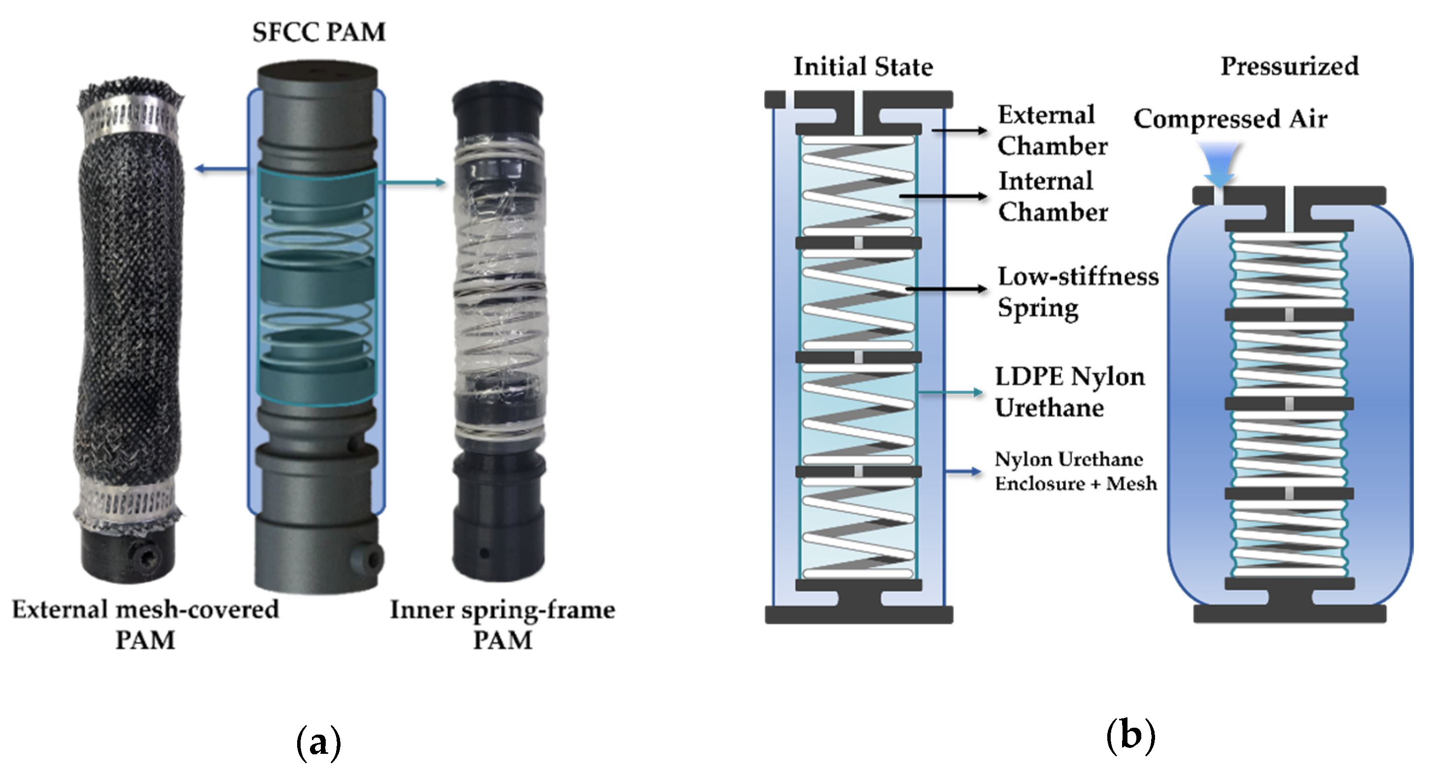
Figure 1 presents the detailed schematic of the internal and external actuators.
2.1.1. External Mesh-Covered Actuator
First, the external mesh-covered actuator (i.e., external actuator) must exert a high actuation force with sufficient actuation speed for wearable robot applications. Like the conventional McKibben muscle, the external actuator consists of an elastomer tube to exert a contraction force in the longitudinal direction and the braided mesh to limit the volume expansion. Numerous studies have attempted to enhance the force density of PAMs, but McKibben muscles are thought to be the most practical solution for various types of robotic systems [
25]. To obtain the desired actuation performance, McKibben muscles are desirable due to high force density, safety, simplicity, lightweight, etc. However, once compressed air is inserted into a McKibben muscle, the latex tube expands and further increases the wasted space. Thus, we designed an internal spring-frame actuator (i.e., internal actuator) to utilize the wasted space and subsequently enhance the actuation performance of the PAMs.
Next, in order to actuate the external actuator with the internal actuator, both actuators must be simultaneously contracted once pressurized. This is made possible by allowing the internal actuator to contract by the air pressure of the external chamber. If the contraction length of the external actuator is designed to be longer than the internal actuator, the internal actuator will contract to a maximum contraction length prior to the contraction length of the external actuator. Once this happens, the external actuator will cause SFCC PAM to be slacked (loosened state with uncontrollable manner) and interfere with the actuation performance of each other. Thus, the contraction length of the external actuator must be designed to be shorter than the internal actuator.
2.1.2. Inner Spring-Frame Actuator
Unlike conventional vacuum actuators, the internal actuator is designed to operate by increasing the external pressure and subsequently reducing the relative internal pressure of the actuator. When the pressure of the outer chamber increases, force is applied to the inner chamber and consequently contracts the inner chamber. Here, the pressurized air within the inner chamber is exhausted, and the internal pressure is maintained at the atmospheric level. Since the internal actuator contracts due to the pressure difference between the external and internal chambers, the internal actuator can exert a higher force than the conventional vacuum actuators.
Although the working principle of the internal actuator is similar to that of conventional vacuum actuators, the internal actuator was more susceptible to buckling because pressure was applied via the external chamber. Previous studies used a toroidal sphere to suppress the buckling, but the contraction length is limited due to the sphere volume [
21]. Thus, to address the buckling issue, an elastic element needs to be added to the internal actuator to provide a rigid support while providing sufficient contraction length. Hence, we selected a compressive spring with sufficient stiffness to prevent the spring from interfering with the contraction force of the internal actuator. Since the compressive spring exhibits low stiffness in the axial direction, it can provide rigid support in the radial direction of the internal actuator without degrading the actuation force performance of the internal actuator.
2.2. Fabrication
We fabricated two actuators of the same size to compare the existing and proposed actuators.
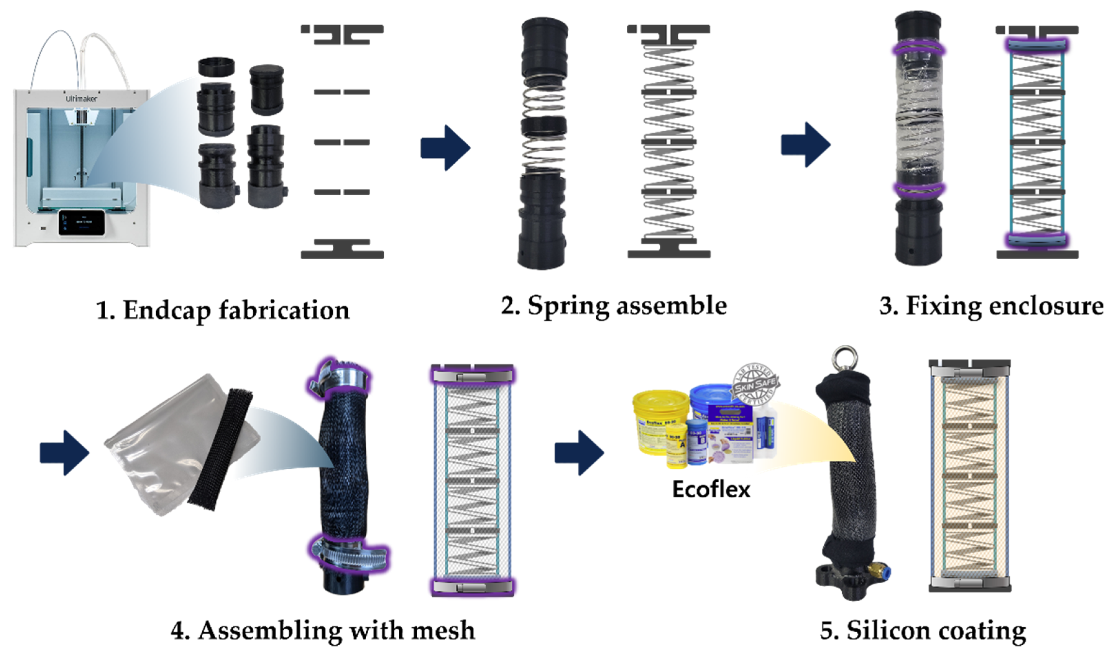
Figure 2 shows the fabrication process of the SFCC PAM. The caps at both ends require rather complicated air hole lines inside to afford high performance by maximizing the actuator size. To ensure stable and independent airflow to each part, we used a 3D printer (Ultimaker S5, Ultimaker BV) (Ultimaker BV, Utrecht, Nederland) to print light and rigid endcaps for maintaining airtightness.
Table 1 shows 3d printer setting parameters. The suggested SFCC PAM and McKibben PAM with only external parts were manufactured to have the same volume and stroke. The weight of SFCC PAM after fabrication is 180 g and McKibben PAM is 160 g.
The internal part of the SFCC PAM requires an additional chamber isolated from the air source of the external chamber for differential pressure driving. To minimize the internal actuator from buckling, during contraction, spring frames were fixed to the endcaps. Low deformation LDPE–nylon–urethane–vinyl film was used for the internal enclosure to withstand high pressure. The enclosure was fixed to a spring frame by wrapping the endcap with a high-strength string. The stroke length of inner part is 95 mm and the diameter is 30 mm.
The external part of the SFCC PAM consists of an elastic nylon–urethan–vinyl enclosure and urethane fiber mesh to maximize contraction length. Because the external part of both McKibben muscle and the proposed PAM are identical, the McKibben PAM endcap is manufactured with the same shape, but only with a single input airhole. Furthermore, to prevent damage to the external enclosure by large elastic strain (or elongation), highly compliant silicone (Ecoflex 50, Smooth-On Inc.) (Macungie, PA, USA) was applied to the outside of the fabricated actuator. The stroke length of external part is 130 mm and the diameter is 35 mm.
3. Modeling
The force of the proposed actuator is equal to the pressure between the external and internal actuators at the current actuator length. The total actuation force, which stems from the force of the external and internal actuators, is expressed in Equation (1). The force of each actuator can be derived by using virtual work approach with some assumptions. For the simplification process, we have neglected the material’s elasticity based on the assumption that the enclosure maintains cylindrical shape as the actuator contracts. The resulting actuation force derived from the virtual work approach is shown in Equation (2), where F is force, L is axial displacement, V is volume, and P is pressure [
26].
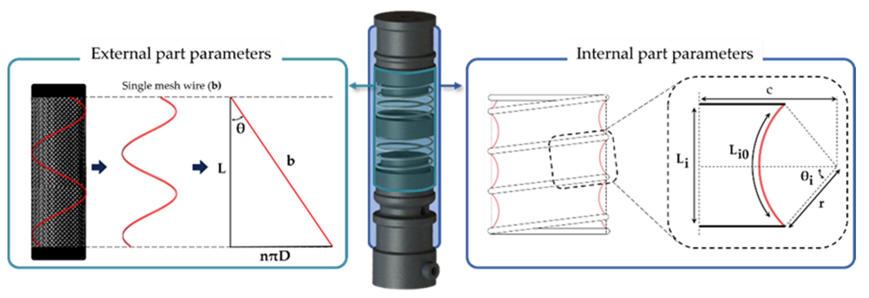
The external actuator and McKibben muscle contraction force can also be represented with a virtual work approach by using positive pressure and the force of the fiber mesh, while limiting the volume change of the enclosure [
27]. In the equation below, b is the length of the mesh wire,
is the angle between the mesh wires, and D is the diameter of the internal actuator, as depicted
Figure 3. At this time, the volume
during contraction can be expressed in the form of Equation (3). By applying the virtual work approach to Equation (3) external force,
can be determined by using Equation (4).
Next, to derive the contraction force of the internal actuator, we must first find the internal volume. By assuming that the segment between the spring pitches of the internal actuator is a cylindrical bellow shape, we can first define the required design parameters as shown in
Figure 3, bottom. The enclosed area highlighted in black dotted lines has a circular arc shape with a radius of r, an angle of
, the arc length before contraction of
, and distance between the springs during contraction of
. With the parameters shown in the figure, the following relation can be found:
Considering Equations (5) and (6), the internal volume
can be redefined as follows:
The differential pressure between the positive and atmospheric pressures generates the contraction force of the internal actuator. The contraction force of the internal actuator can also be described according to the virtual work principle [
28]. Because the internal actuator is designed to maintain pressure at an atmospheric level, the differential pressure acts as a negative pressure, and it works like a vacuum actuator. Furthermore, the internal spring acts as a guide that maintains the shape of the internal actuator during contraction, but the elastic modulus k should be considered to prevent interference during the contraction. Consequently, the contraction force of the internal actuator is rearranged as Equation (7).
The contraction force derived from the differential pressure can be arranged for , and it can be calculated using Equation (7). The calculated values were derived using the symbolic tool in MATLAB (MathWorks Inc.) (Boston, MA, USA). However, the derivation process was omitted for simplification. The mathematically derived force tendency model will be further compared to the experimental results section for validation.
4. Experimental Validation
In this section, we have validated the performance of the proposed actuation mechanism via the following experiments: (1) actuation force experiment by comparing the actuation stroke with respect to the applied pressure, (2) actuation speed experiment by evaluating the position tracking performance of a single degree of freedom antagonistic joint, and (3) actuation efficiency experiment by comparing the amount of air consumed while using two actuators with the equal maximum static force during the same task. All experiments were conducted in comparison to a conventional McKibben pneumatic muscle.
4.1. Static Contraction Force
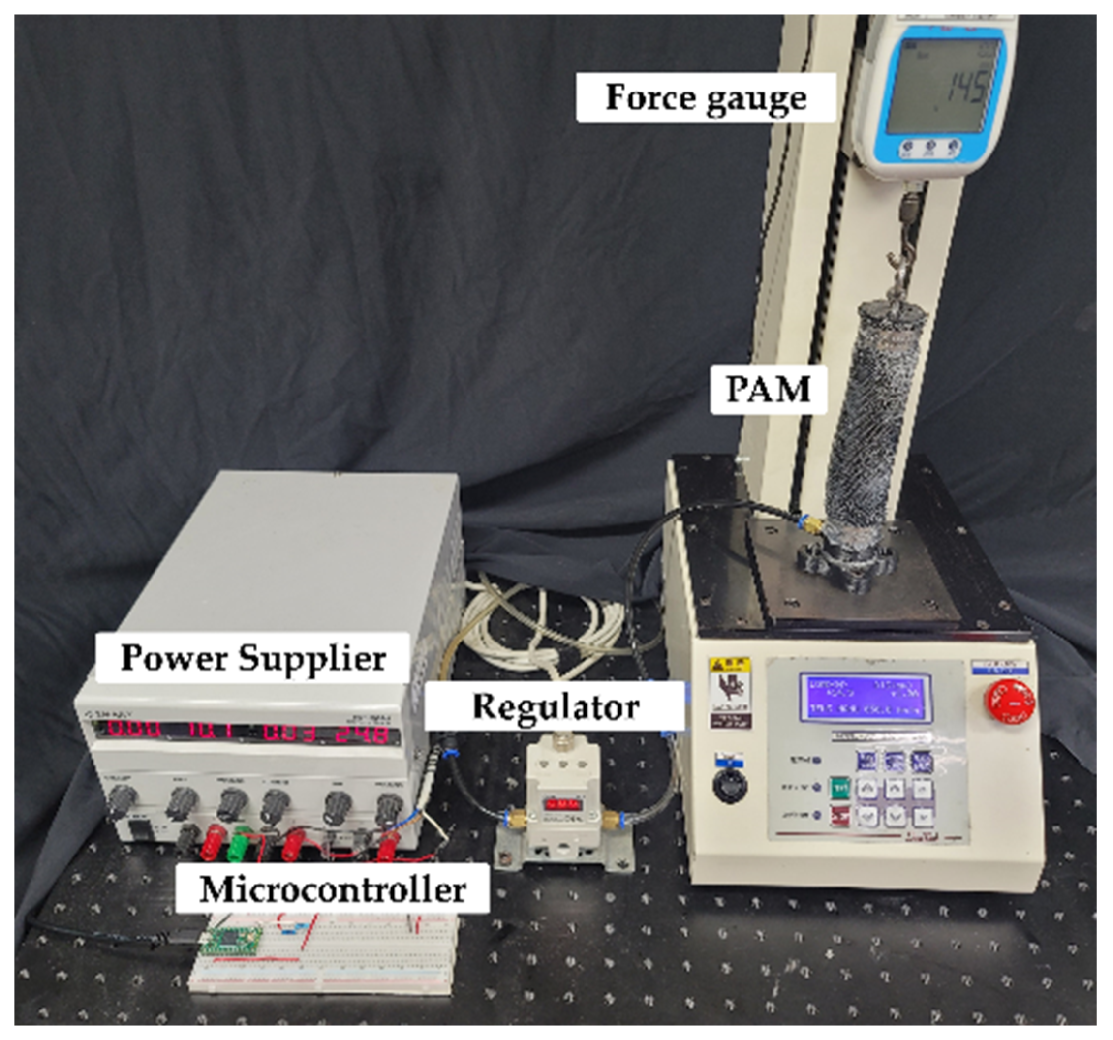
For fair comparison, the proposed PAM and McKibben PAM which are manufactured in the same size, were evaluated under quasistatic condition with equal pressure air input. For the experimental setup, a force gauge (DigiTech, DTG-100) (DigiTech, Osaka, Japan) was used to measure the output force and a regulator (SMC, ITV-1050) (SMC, Tokyo, Japan) was used to control the input pressure according to the control input from a microcontroller (PJRC, Teensy 4.0) (PJRC, Portland, OR, USA).
Figure 4 displays the detailed overview of the experimental setup. The contraction length of the actuators was evaluated after applying pressure to the actuators that were subjected to zero external load. Note that the actuation force data were recorded for every 5 mm contraction length. The detailed experimental method is as follows: (1) Set the PAM to initial length. (2) Inject compressed air into the PAM. (3) Measure the force of the PAM. (4) Reduce the length of the PAM by 5 mm. (5) Repeat steps 2 to 4 until the force of the PAM is not measured.
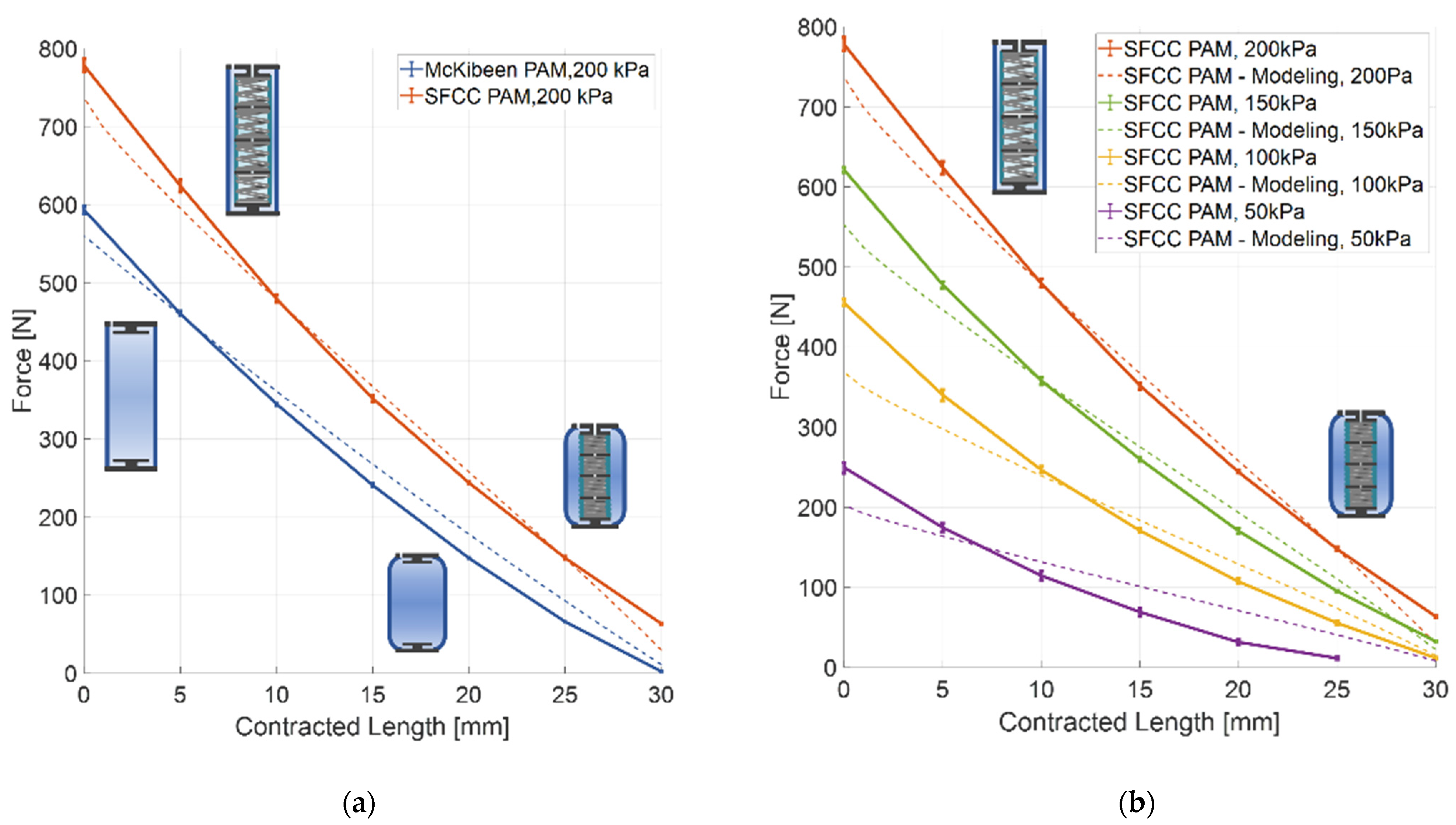
The experimental result,
Figure 5a shows that under an applied pressure of 200 kPa, the proposed PAM could exert up to 778.2 N actuation force, whereas the McKibben muscle can exert up to 593.3 N actuation force. The actuation force of the proposed PAM increased by nearly 50% during the recorded datasets and by 31.2% at the maximum actuation force. Since the SFCC PAM has 12.5% more weight, the force to weight increases by 16.6% for the same weight. Notably, the maximum actuation force of the McKibben muscle can be reached by the SFCC PAM with an applied pressure of 160 kPa only, which is 40 kPa below the maximum applied pressure (nearly 20% lower pressure).
Figure 5b shows the comparison between the simulation and experimental data, the results show good agreement with the mathematical model. Since the proposed PAM affords greater actuation force performance than the McKibben muscle under same conditions of applied pressure and volume, the proposed PAM is highly applicable for soft wearable robots.
4.2. Dynamic Condition Performance
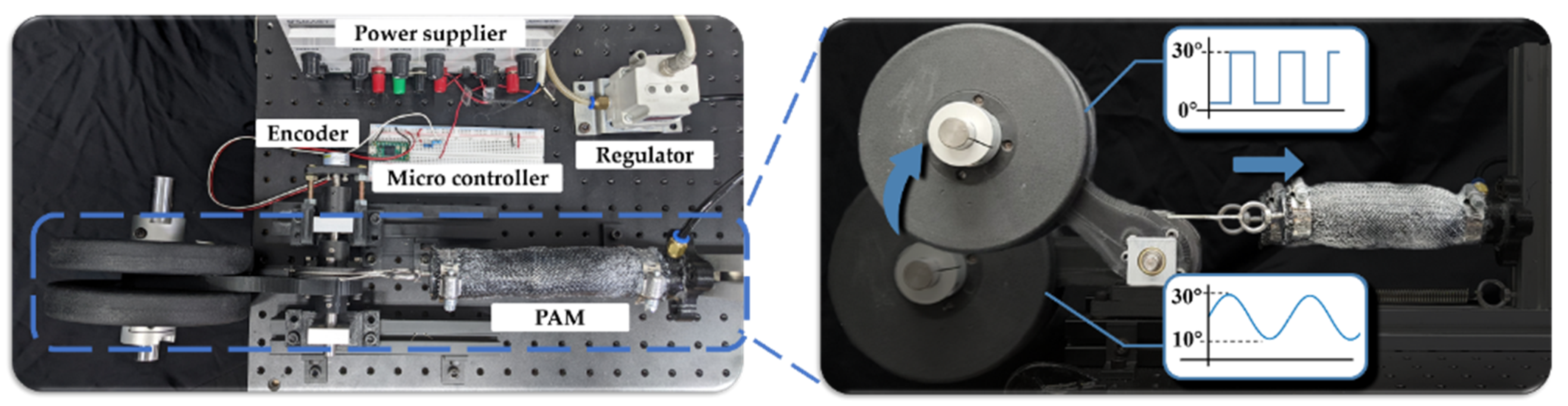
To evaluate the actuation speed, a single degree of freedom robot joint was developed by antagonistically installing an actuator and a spring, as shown in
Figure 6. Two different types of control inputs were used for the experiment: (a) step input with a desired angle of 30° and (b) 0.5 Hz sinusoidal input with a sinusoidal input of 10–30° to compare the position tracking performance. For the external loading, a 4 kg mass was attached to a 150 mm moment arm for (a). The limit weight the PAM can lift with a 7.5 kg and 10 kg mass were attached to a 150 mm moment arm for each PAM in (b).
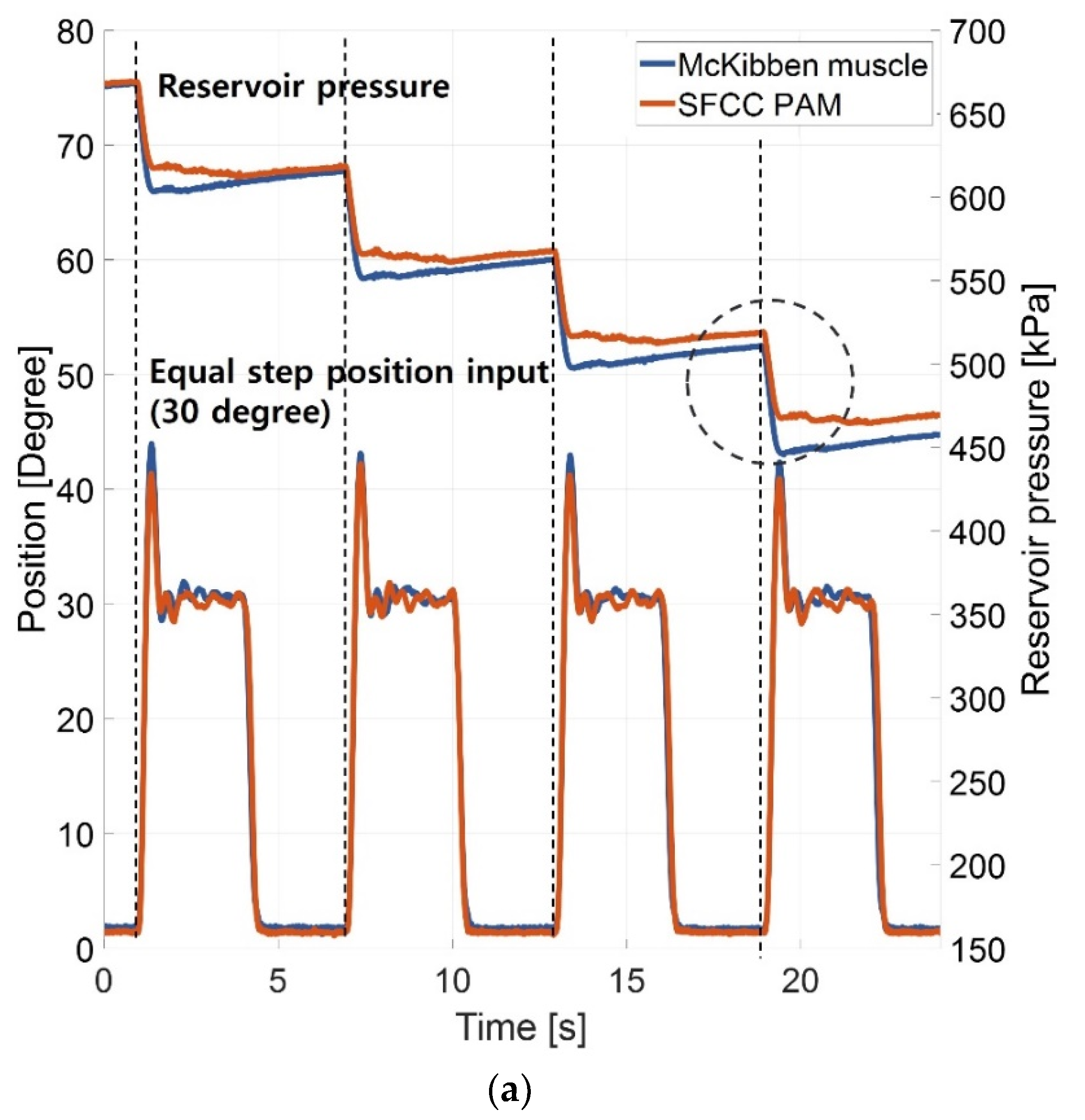
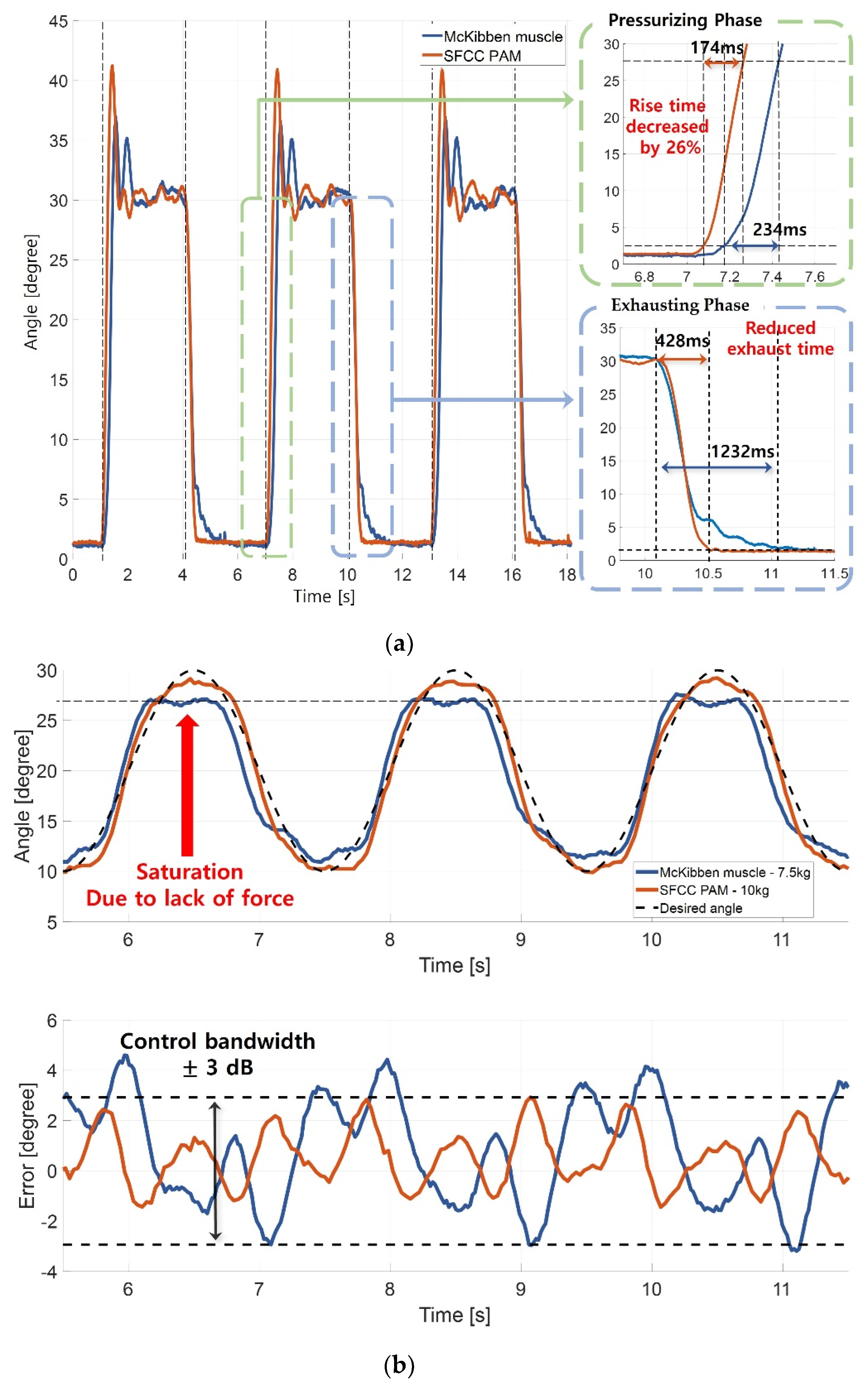
Figure 7a displays the actuation speed of the McKibben muscle and the proposed SFCC PAM. Under the step input of 30°, the rise time of the proposed SFCC PAM decreased by 25.6% compared to the McKibben muscle. During the sinusoidal input, the McKibben muscle was unable to track the desired position with 7.5 kg weight only, whereas the proposed PAM exhibited exceptional position tracking performance even with 10 kg weight, as shown in
Figure 7b.
The experimental result validates that both the external and internal actuators of the proposed SFCC PAM operated simultaneously during the compression phase. Thus, the proposed SFCC PAM affords better control tracking performance with the same system volume; enhanced control tracking performance of the proposed SFCC PAM further verifies the applicability of the proposed PAM for the wearable robots.
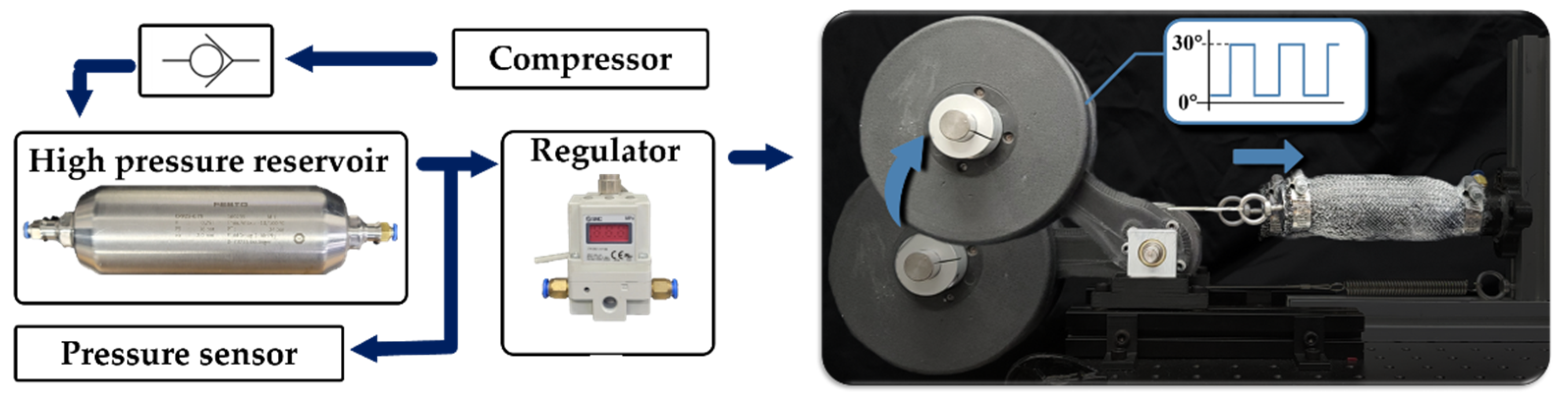
4.3. Air Consumption
For the last experiment, the actuation efficiency was evaluated by comparing the amount of air consumed by the two different actuators while executing the same task. Although the experimental setup was similar to that in
Section 4.2, a 750 mL reservoir (Festo Inc., CRVZS 0.75) (Esslingen am Neckar, Germany) and a check valve were installed between the regulator and the compressor to measure the amount of air consumed as shown in
Figure 8. Assuming that all the parameters are equal for both setups, we can employ the ideal gas law (
) to evaluate the air consumption by measuring the change in pressure only.
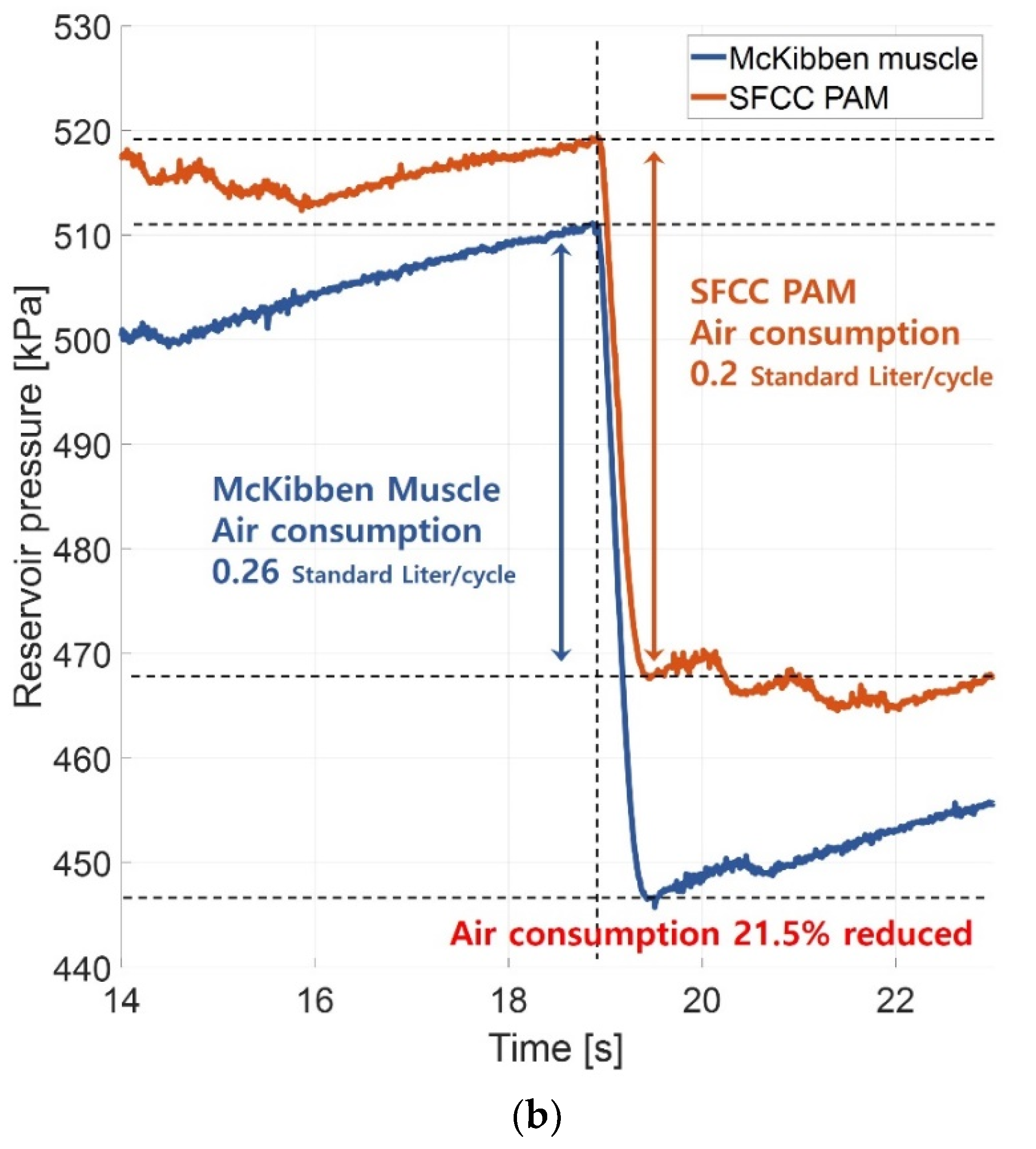
Figure 9a shows the experimental results and
Figure 9b shows an enlarged comparison of air consumption results. Faster operation is possible under the same regulator and pressure conditions, enabling faster response to the surrounding environment.
5. Discussion and Conclusions
Although the feasibility of PAMs on soft robots has been validated, overcoming the actuation efficiency, large overhead, etc., which limit their applications in soft mobile robots has been an ongoing challenge.
To overcome this challenge, we proposed a novel PAM based on SFFC mechanism. The proposed SFCC mechanism stands out in improving all of the contraction force, actuation speed, and efficiency compared to the contractile soft actuators of previous studies [
20,
22,
24]. In addition, compared to the previous studies of the improved McKibben-type actuators [
21,
29], we increased the contraction length and minimized the reduction of contraction force due to buckling of the inner part with the spring frame internal actuator. The proposed SFFC PAM simultaneously contracts both the external and internal actuators and exerts 31% higher actuation force than the conventional McKibben PAM. The proposed SFFC mechanism increased the actuation speed (rise time reduced by 25.6%) by successfully reducing the internal volume of the actuator. The proposed mechanism exhibits not only enhanced actuation force and speed but also 21.5% better actuation efficiency than that of the conventional actuator by reducing the amount of air consumption.
Owing to the improved actuation performance, the proposed PAM is expected to broaden the applicability of PAMs in mobile soft robots, such as wearable robot, with its compact design. By improving the actuation force, the proposed SFCC PAM can be implemented to augment the human joints with a large RoM (e.g., shoulder and hip) with its relatively compact design. The improved actuation efficiency reduces the air consumption required for actuation, which subsequently reduces the overheads (i.e., compressor and reservoir) required for the actuation system. Despite these advantages, the inner part of SFCC PAMs are composed of rigid spring frames, which makes them relatively stiffer than the McKibben PAM. Because the human body consists of a compliant body with varying curvature, the relative stiffness marginally limits the application of the SFCC PAM to a wearable robot with large change in human body curvature. Thus, we aim to conduct further research to design a wearable robot based on the SFCC PAM that can adapt to the different curvatures of the human body. In the future, we aim to develop a new soft wearable suit by implementing the proposed PAM onto human joints with large RoM and validating its performance.
Author Contributions
Conceptualization, methodology, experimental setup, drafted the paper andrevised the paper, S.K.; Data analysis and reviewed the paper for submission, S.R.L.; experimental setup, reviewed the paper for submission, S.L.; reviewed the paper for submission, D.L.; supervised overall work the paper, D.S.; S.K. and S.R.L. contributed equally to this paper. All authors have read and agreed to the published version of the manuscript.
Funding
This work was supported by the National Research Foundation of Korea (NRF) Grant funded by the Korean government (MIST) (NRF-2016R1A5A1938472), in part by the Industrial Technology Innovation Program (No. 20007058, Development of safe and comfortable human augmentation hybrid robot suit) funded by the Ministry of Trade, Industry & Energy (MOTIE, Korea), and in part by the Chung-Ang University Research Scholarship Grants in 2020.
Institutional Review Board Statement
Not applicable.
Informed Consent Statement
Not applicable.
Data Availability Statement
Not applicable.
Acknowledgments
The authors thank the people in the Human-Centered Robotics Laboratory at Chung-Ang university for their valuable comments and feedback.
Conflicts of Interest
The authors declare no conflict of interest.
References
- Barjuei, E.S.; Toxiri, S.; Medrano-Cerda, G.A.; Caldwell, D.G.; Ortiz, J. Bond graph modeling of an exoskeleton actuator. In Proceedings of the 10th IEEE Computer Science and Electronic Engineering, Colchester, UK, 19–21 September 2018; pp. 101–106. [Google Scholar]
- Wang, S.; Van Dijk, W.; Van Der Kooij, H. Spring uses in exoskeleton actuation design. In Proceedings of the 12th IEEE International Conference on Rehabilitation Robotics, Zurich, Switzerland, 29 June–1 July 2011; pp. 1–6. [Google Scholar]
- Shao, Y.; Zhang, W.; Su, Y.; Ding, X. Design and optimisation of load-adaptive actuator with variable stiffness for compact ankle exoskeleton. Mech. Mach. Theory 2021, 161, 104323. [Google Scholar] [CrossRef]
- O’Neill, C.T.; Phipps, N.S.; Cappello, L.; Paganoni, S.; Walsh, C.J. A soft wearable robot for the shoulder: Design, characterization, and preliminary testing. In Proceedings of the 15th International Conference on Rehabilitation Robotics, London, UK, 17–20 July 2017; pp. 1672–1678. [Google Scholar]
- Wehner, M.; Tolley, M.; Mengüç, Y.; Park, Y.-L.; Mozeika, A.; Ding, Y.; Onal, C.; Shepherd, R.F.; Whitesides, G.M.; Wood, R.J. Pneumatic energy sources for autonomous and wearable soft robotics. Soft Robot. 2014, 1, 263–274. [Google Scholar] [CrossRef] [Green Version]
- Yun, S.; Kang, B.B.; Cho, K. Exo-glove PM: An easily customizable modularized pneumatic assistive glove. IEEE Robot. Autom. Lett. 2017, 2, 1725–1732. [Google Scholar] [CrossRef]
- Yap, H.K.; Lim, J.H.; Nasrallah, F.; Goh, J.C.; Yeow, R.C. A soft exoskeleton for hand assistive and rehabilitation application using pneumatic actuators with variable stiffness. In Proceedings of the IEEE international conference on robotics and automation, Seattle, WA, USA, 25–30 May 2015; pp. 4967–4972. [Google Scholar]
- Park, Y.L.; Santos, J.; Galloway, K.G.; Goldfield, E.C.; Wood, R.J. A soft wearable robotic device for active knee motions using flat pneumatic artificial muscles. In Proceedings of the 2014 IEEE International Conference on Robotics and Automation, Hong Kong, China, 31 May–5 June 2014; pp. 4805–4810. [Google Scholar]
- Shin, D.; Yeh, X.; Khatib, O. A new hybrid actuation scheme with artificial pneumatic muscles and a magnetic particle brake for safe human–robot collaboration. Int. J. Robot. Res. 2014, 33, 507–518. [Google Scholar] [CrossRef]
- Shin, D.; Yeh, X.; Narita, T.; Khatib, O. Motor vs. In brake: Comparative studies on performance and safety in hybrid actuations. In Proceedings of the 13th Symposium on Experimental Robotics, Québec City, QC, Canada, 18–21 June 2012; pp. 101–111. [Google Scholar]
- Zhang, J.; Sheng, J.; O’Neill, C.T.; Walsh, C.J.; Wood, R.J.; Ryu, J.H.; Desai, J.P.; Yip, M.C. Robotic artificial muscles: Current progress and future perspectives. IEEE Trans. Robot. 2019, 35, 761–781. [Google Scholar] [CrossRef]
- Rich, S.I.; Wood, R.J.; Majidi, C. Untethered soft robotics. Nat. Electron. 2018, 1, 102–112. [Google Scholar] [CrossRef]
- Wirekoh, J.; Parody, N.; Riviere, C.N.; Park, Y.L. Design of fiber-reinforced soft bending pneumatic artificial muscles for wearable tremor suppression devices. Smart Mater. Struct. 2020, 30, 015013. [Google Scholar] [CrossRef]
- Majidi Fard Vatan, H.; Nefti-Meziani, S.; Davis, S.; Saffari, Z.; El-Hussieny, H. A review: A comprehensive review of soft and rigid wearable rehabilitation and assistive devices with a focus on the shoulder joint. J. Intell. Robot. Syst. 2021, 102, 9. [Google Scholar] [CrossRef]
- Schiele, A.; Van Der Helm, F.C.T. Kinematic design to improve ergonomics in human machine interaction. IEEE Trans. Neural Syst. Rehabil. Eng. 2006, 14, 456–469. [Google Scholar] [CrossRef] [PubMed]
- Gaponov, I.; Popov, D.; Lee, S.J.; Ryu, J.H. Auxilio: A portable cable-driven exosuit for upper extremity assistance. Int. J. Control Autom. Syst. 2017, 15, 73–84. [Google Scholar] [CrossRef]
- Daerden, F.; Lefeber, D. Pneumatic artificial muscles: A ctuators for robotics and automation. Eur. J. Mech. Environ. Eng. 2002, 47, 11–21. [Google Scholar]
- Lee, S.; Lee, D.; Shin, D. An air recirculation system based on bioinspired soft re-air valve for highly efficient pneumatic actuation. Soft Robot. 2021, 8, 564–576. [Google Scholar] [CrossRef] [PubMed]
- Galiana, I.; Hammond, F.L.; Howe, R.D.; Popovic, M.B. Wearable soft robotic device for post-stroke shoulder rehabilitation: Identifying misalignments. In Proceedings of the 2012 IEEE/RSJ International Conference on Intelligent Robots and Systems, Vila Moura-Algarve, Portugal, 7–12 October 2012; pp. 317–322. [Google Scholar]
- Han, K.; Kim, N.-H.; Shin, D. A novel soft pneumatic artificial muscle with high-contraction ratio. Soft Robot. 2018, 5, 554–566. [Google Scholar] [CrossRef] [PubMed]
- Bishop-Moser, J. High Force Generation Using Inflatable Toroidal Soft Robot Actuators. In Proceedings of the 2019 2nd IEEE International Conference on Soft Robotics, Seoul, Korea, 14–18 April 2019; pp. 222–226. [Google Scholar]
- Xie, D.; Zuo, S.; Liu, J. A novel flat modular pneumatic artificial muscle. Smart Mater. Struct. 2020, 29, 065013. [Google Scholar] [CrossRef]
- Meller, M.; Chipka, J.; Volkov, A.; Bryant, M.; Garcia, E. Improving actuation efficiency through variable recruitment hydraulic McKibben muscles: Modeling, orderly recruitment control, and experiments. Bioinspir. Biomim. 2016, 11, 065004. [Google Scholar] [CrossRef] [PubMed] [Green Version]
- Ogawa, K.; Thakur, C.; Ikeda, T.; Tsuji, T.; Kurita, Y. Development of a pneumatic artificial muscle driven by low pressure and its application to the unplugged powered suit. Adv. Robot. 2017, 31, 1135–1143. [Google Scholar] [CrossRef]
- Tsagarakis, N.G.; Caldwell, D.G. Development and control of a ‘soft-actuated’exoskeleton for use in physiotherapy and training. Auton. Robot. 2003, 15, 21–33. [Google Scholar] [CrossRef]
- Chou, C.P.; Hannaford, B. Measurement and modeling of McKibben pneumatic artificial muscles. IEEE Trans. Robot. Autom. 1996, 12, 90–102. [Google Scholar] [CrossRef] [Green Version]
- Tondu, B. Modelling of the McKibben artificial muscle: A review. J. Intell. Mater. Syst. Struct. 2012, 23, 225–253. [Google Scholar] [CrossRef]
- Usevitch, N.S.; Okamura, A.M.; Hawkes, E.W. APAM: Antagonistic pneumatic artificial muscle. In Proceedings of the 2018 IEEE International Conference on Robotics and Automation, Brisbane, Australia, 21–25 May, 2018; pp. 1539–1546. [Google Scholar]
- Al-Fahaam, H.; Nefti-Meziani, S.; Theodoridis, T.; Davis, S. The design and mathematical model of a novel variable stiffness extensor-contractor pneumatic artificial muscle. Soft Robot. 2018, 5, 576–591. [Google Scholar] [CrossRef] [PubMed]
| Publisher’s Note: MDPI stays neutral with regard to jurisdictional claims in published maps and institutional affiliations. |
© 2022 by the authors. Licensee MDPI, Basel, Switzerland. This article is an open access article distributed under the terms and conditions of the Creative Commons Attribution (CC BY) license (https://creativecommons.org/licenses/by/4.0/).


