1. Introduction
The exoskeleton is a mechanical device that can enhance a human’s strength and endurance. It detects the position of the exoskeleton and the movement intention of the human body in real-time through several kinds of sensing technology [
1]. The brain is responsible for sending out movement intention and maintaining it [
2]. The human body is responsible for issuing movement intentions and maintaining movement stability. Simultaneously, the exoskeleton coordinates movements with the human body and bears loads according to the human movement intentions [
3]. In this way, the human body and the exoskeleton robot are combined. The assisted exoskeleton can guide the wearer’s movement in a predetermined trajectory by applying the necessary torque around the joints. Therefore, generating motion trajectories is a prerequisite to controlling exoskeleton robots [
4,
5]. Suppose motion trajectories can be predicted and incorporated into the control algorithm. In that case, this may help with delays in control response time due to the inclusion of feedforward terms to compensate for the system’s data operations. Both model-based and machine learning-based approaches have been extensively investigated in motion trajectory prediction [
6].
Model-based optimization methods are popular for predicting motion trajectories from biomechanical models, such as hill-type muscle models, musculoskeletal models, and models that calculate energy loss under specific constraints. BLEEX in the USA was the first to use sensitivity amplification control (SAC) [
7], which does not require any sensors in the human body or between the human body and the machine. Instead, it follows a predetermined ideal motion trajectory based on plantar sensor signals. This method requires identifying the physical parameters of the exoskeleton and the human body accurately, such as mass and inertia, to achieve the control effect. Otherwise, the higher sensitivity will enlarge the system’s response due to the inconsistency of the motion between the human and machine. In some research, the control strategies are altered to position control to minimize the interacting forces between the human body and the exoskeleton during movement. In this case, an electromyographic (EMG) signal is used to detect the wearer’s moving intention. Potentiometers and gyroscopes are also employed to detect the operating state of the exoskeleton system. Some researchers also use mapping relations to obtain the ideal torque required for the knee joint.
According to the actual angle of joint measured by the encoder of the serial elastic actuator (SEA), the inference result of SEA can be attained. With this method, the proportional-differential control of the DC motor can be realized. The reliability and applicability of these methods rely on accurate biomechanical models. As such, deviations in the model will affect the prediction of the gait trajectory. In short, to achieve precise control of the exoskeleton, we must first accurately predict the gait trajectory [
8].
There are many gait detection methods. Such as [
9], the plantar force was predicted using only data measured by inertial measurement unit sensors. In [
10], surface electromyography (sEMG) was used to reflect the motion intention of the human body ahead of muscle action. In [
11], the foot trajectory estimated by an IMU was used to derive the inclination grade of the terrain that they traverse to identify the locomotion mode. In [
12], human motion was analyzed, and the accuracy of predicting lower extremity joint angular position based on cane motion was investigated. Data processing methods include threshold methods, machine learning methods, etc., and the simplest calculation method in gait detection is the threshold value. There are different thresholding algorithms as the value rules to determine specific characteristics of gait phases or events. Machine learning (ML) methods are used to classify gait phase offline data and real-time data. Different machine learning methods, such as HMMs, NN models, DLNNs, and CNNs, have been used for gait stage recognition [
13]. ML methods are among the most popular techniques used to classify gait phases in offline data and real-time data. These methods are based on a large amount of data, and can get rid of complex biomechanical models and energy loss equations, so many studies regard the gait trajectory as a time series [
14]. In this way, the prediction of the gait trajectory is essentially a time series prediction. The gait trajectory can be predicted based on the previous state parameters [
15]. Zaroug et al. [
16] used automatic coding to predict the kinematics trajectory of the lower limbs. Using primarily linear acceleration and angular velocity, the correlation coefficient between the predicted gait trajectory and the measured trajectory was 0.98. Many methods have been developed based on an artificial neural network to estimate parameters of the gait phase [
17,
18,
19]. Liu et al. [
20] presented a neural network model that could detect eight phases offline with an accuracy of only 87.2–94.5%. Moreira et al. [
21] applied an LSTM model to generate reference ankle torques for a healthy human walking on level ground. Using this model, they achieved a normalized RMSE of 4.31% and demonstrated the potential of LSTM to be integrated into a robot assistive device control. However, it is worth noting that gait trajectory prediction without accurate lower limb exoskeleton motion information is verified only at the simulation stage.
This paper proposed and verified a LSTM model for gait prediction by the CMU human gait database. Then, a wearable joint angle measurement device was designed. The experimental results show that the LSTM prediction model can effectively predict human walking data.
2. LSTM Gait Prediction Model
The gait trajectory can be predicted by collecting the human trajectory. These prediction methods only predict the human trajectory but not the lower limb exoskeleton system’s trajectory. This paper presents a machine learning algorithm for motion trajectory prediction based on the Long Short Term Memory network (LSTM). This machine-learning algorithm has been widely used for temporal signal prediction and classification.
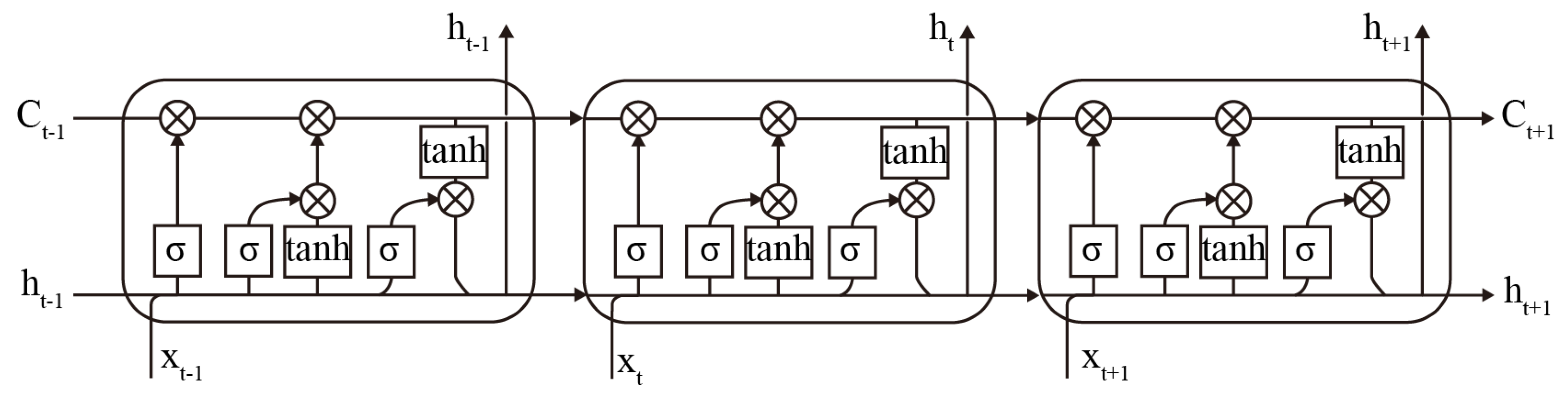
The LSTM is a particular type of RNN. The underlying structure of an LSTM, like an RNN, is a chained form of repeating neural network modules. However, in an RNN, the repeating module is a straightforward
layer. The LSTM has four unique layers for interaction between the input and output, as
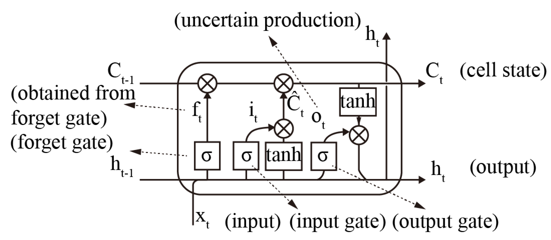
Figure 1. A key concept in the LSTM network is the cell state, which is like a constantly updated cell. It can remove or add information to the cell state through an elaborate structure called a gate. There are three gates to update the cell state: the forget gate, the input gate, and the output gate. The forget gate and the input gate are the main parts of the LSTM, as
Figure 2, that keep the network active and determine the information which to be discarded and retained when the network is iteratively updated.
The first step in the LSTM is to decide what information it will discard from the cell state. This decision is made through a sigmoid layer called the forget gate by reading the output information
ht−1 from the previous moment and the input information
xt from the current moment. It outputs a value
ft between 0 and 1 to each number in the cell state. One means full retention, and zero means full discard; the expression is as follows:
The next step is to determine what new information is stored in the cell state. Firstly, a sigmoid layer called an input gate determines the values
it to be updated. Secondly, a vector
of new cell state candidates is created using a tanh layer.
The old cell state
Ct−1 is then multiplied by
ft obtained from the “forgetting gate”, and the updated value
it obtained from the “input gate” is then added to the product of the new cell candidate vector
. to obtain the latest cell state
; the expression is as follows:
Ultimately, the output, or predicted outcome, needs to be determined. The result will be based on the current state of the cell
. The input information
xt at the present moment is passed through a sigmoid layer to determine the outcome of the pending output
Ot. The uncertain production
Ot is multiplied by the cell state
and is processed by the layer to obtain the result
ht determined at the current moment.
For the motion trajectory prediction model, the input to the LSTM network is the sampled joint angle trajectories from the lower limb exoskeleton, defined as
Xt = {
xtRH,
xtRK,
xtRA,
xtLH,
xtLK,
xtLA,}, and the output
Yt + 1 = {
yt + 1RH,
yt + 1RK,
yt + 1RA,
yt + 1LH,
yt + 1LK,
yt + 1LA,}, which is the predicted value of each joint angle trajectory for the next moment. To evaluate the performance of the LSTM network for motion trajectory prediction, we used the root mean square error (RMSE) to quantify the variability between the predicted and actual observed values of the motion trajectory.
3. Prediction and Analysis of Gait Trajectory
CMU Graphics Lab Motion Capture Database gives an overview of the mocap process at CMU. The mocap lab in the basement of Wean contains 12 Vicon infrared MX-40 cameras, each of which can record 120 Hz with images of 4-megapixels of resolution. The cameras are placed around a rectangular area of approximately 3 × 8 m in the centre of the room and small grey markers are placed on it. Humans wear a black jumpsuit, which has 41 markers taped on it. The Vicon cameras see the markers in infra-red. The images that the cameras pick up are triangulated to obtain 3D data. We used walking gait data in the CMU database as a data source for analysis and use MATLAB 2020b to build an LSTM prediction model.
For an LSTM model, it was defined as follows. The number of input features and the number of output responses were six, and the number of hidden units in the network was set to 200. The training solver was set to 250 rounds of training. To prevent gradient explosion, we set the gradient threshold to 1. The initial learning rate was 0.005, which was reduced by multiplying by a reduction factor of 0.5 after every 50 rounds of training.
The dataset is a sampling of joint angle trajectories from the lower limb exoskeleton in the co-movement experiment, including the right hip (RH), right knee (RK), right ankle (RA), left hip (LH), left knee (LK), and left ankle (LA). First, the training data must be normalized to a dataset with a zero mean and unit variance to prevent training scatter. The dataset was divided into a training dataset and a test dataset in a ratio of 6:4. Our goal was to use past historical joint trajectories to predict joint trajectories for the next time step, where we defined the prediction time step as 1 sample point. The exoskeleton’s historical joint angle trajectory vector was used as the input vector to the LSTM network. The predicted joint motion trajectory was the output vector of the LSTM.
3.1. Conventional LSTM
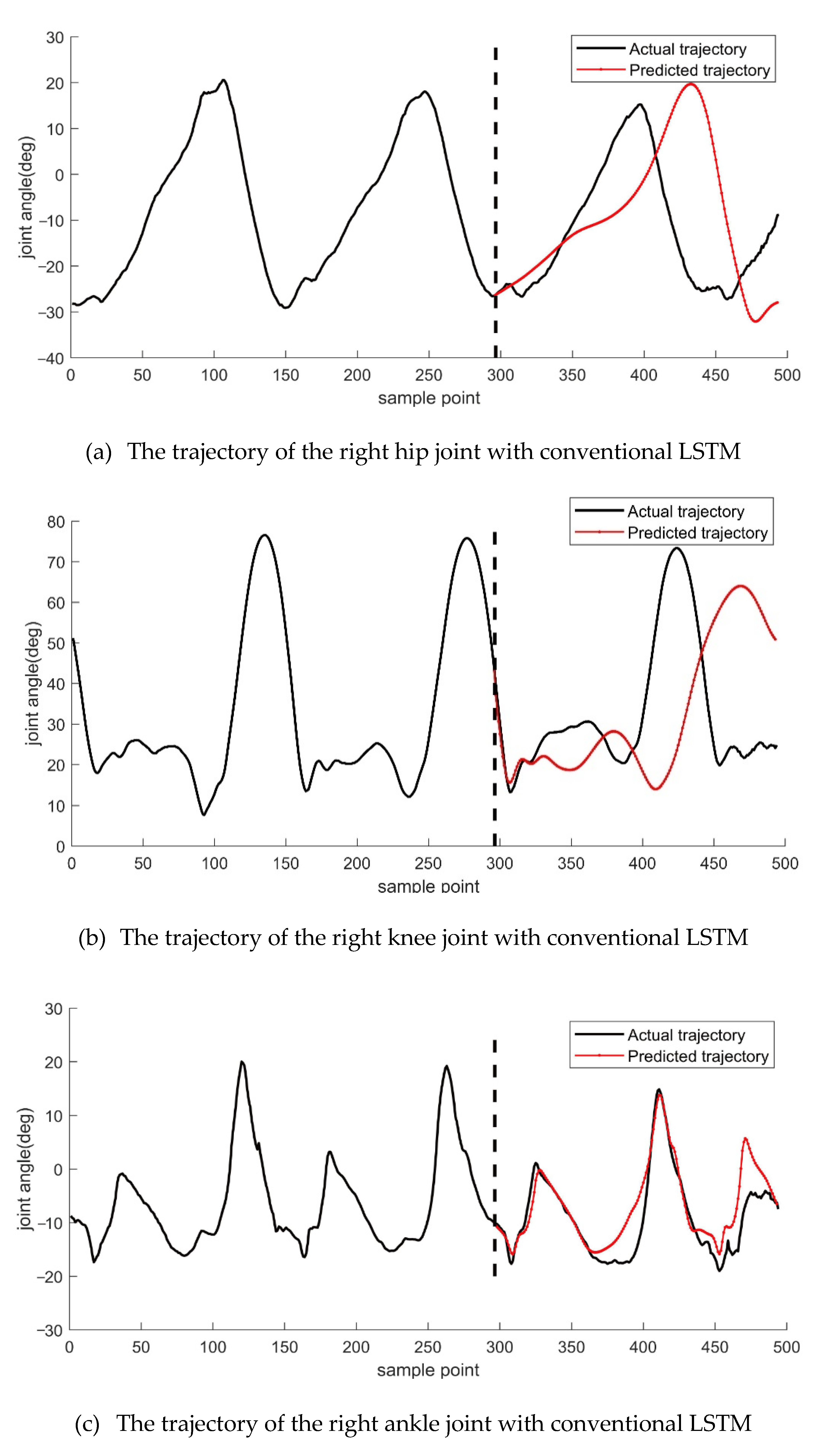
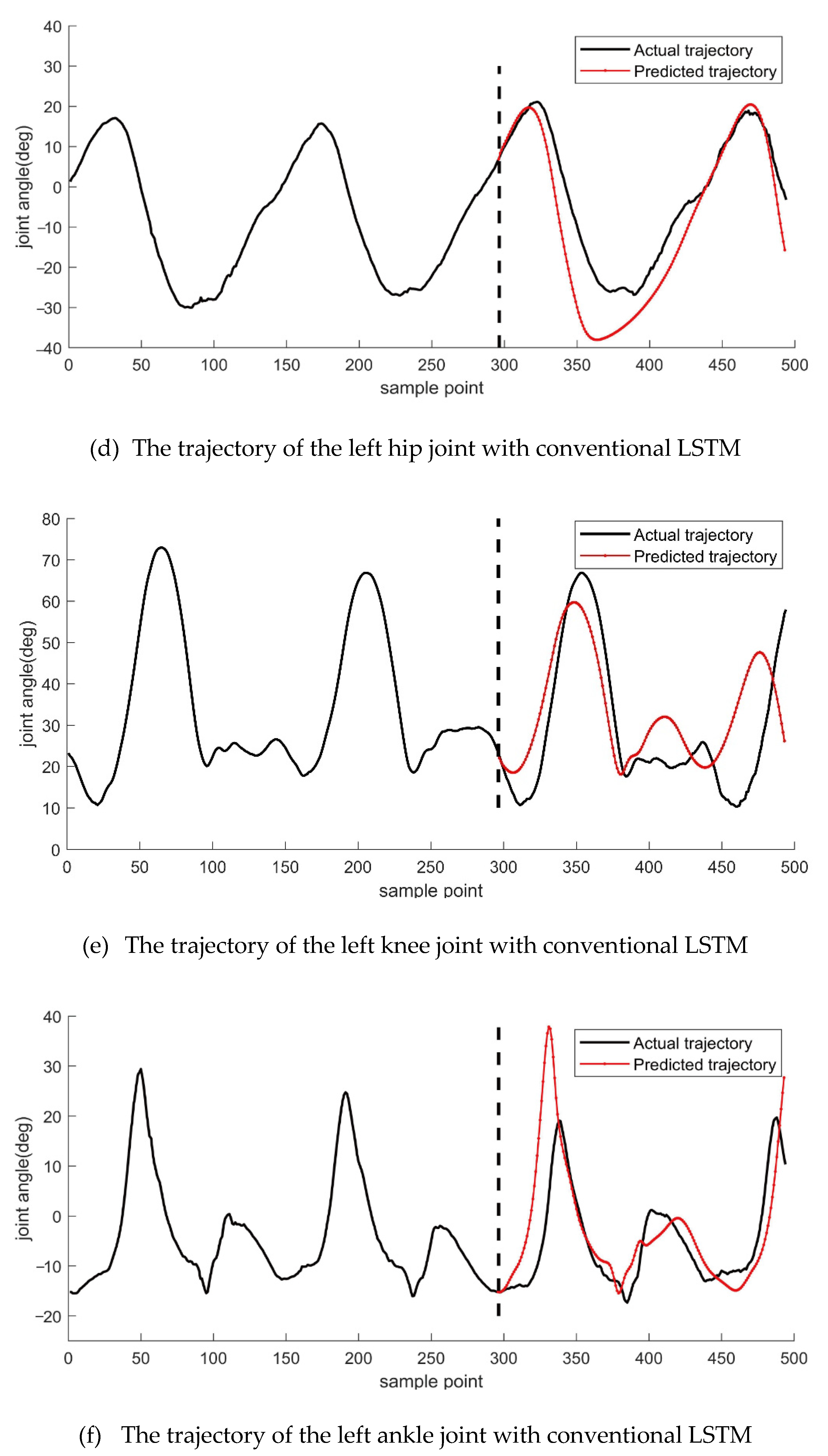
In a conventional LSTM prediction model, continuously predicting the motion trajectory at the next moment requires continuous input to the LSTM network based on data from the previous moment, followed by a prediction result. We first used a conventional LSTM model to predict the motion trajectory. The following
Figure 3 displays the results.
From the data in
Figure 3, we can observe that the predicted motion trajectories of the left and right legs at the hip, knee, and ankle joints on both sides of the lower limb are significantly different. The predicted motion trajectories of the left and right legs at the hip joint are significantly similar to the actual motion trajectories. Still, the predicted trajectories do not overlap with the actual trajectories, indicating that the predicted trajectories at the hip joint were too far ahead. The predicted trajectories at the knee joints of the left and right legs showed the good accuracy in the beginning, then the accuracy gradually decreased as time goes on. They could not accurately predict the motion trajectories for an extended period, and the predicted trajectories at the ankle joints of the left and right legs showed a certain amount of over-advancement. However, they showed an inevitable trend of similarity with the actual trajectories, but the overall prediction results also deviated significantly.
3.2. LSTM Prediction Model with Observation Update
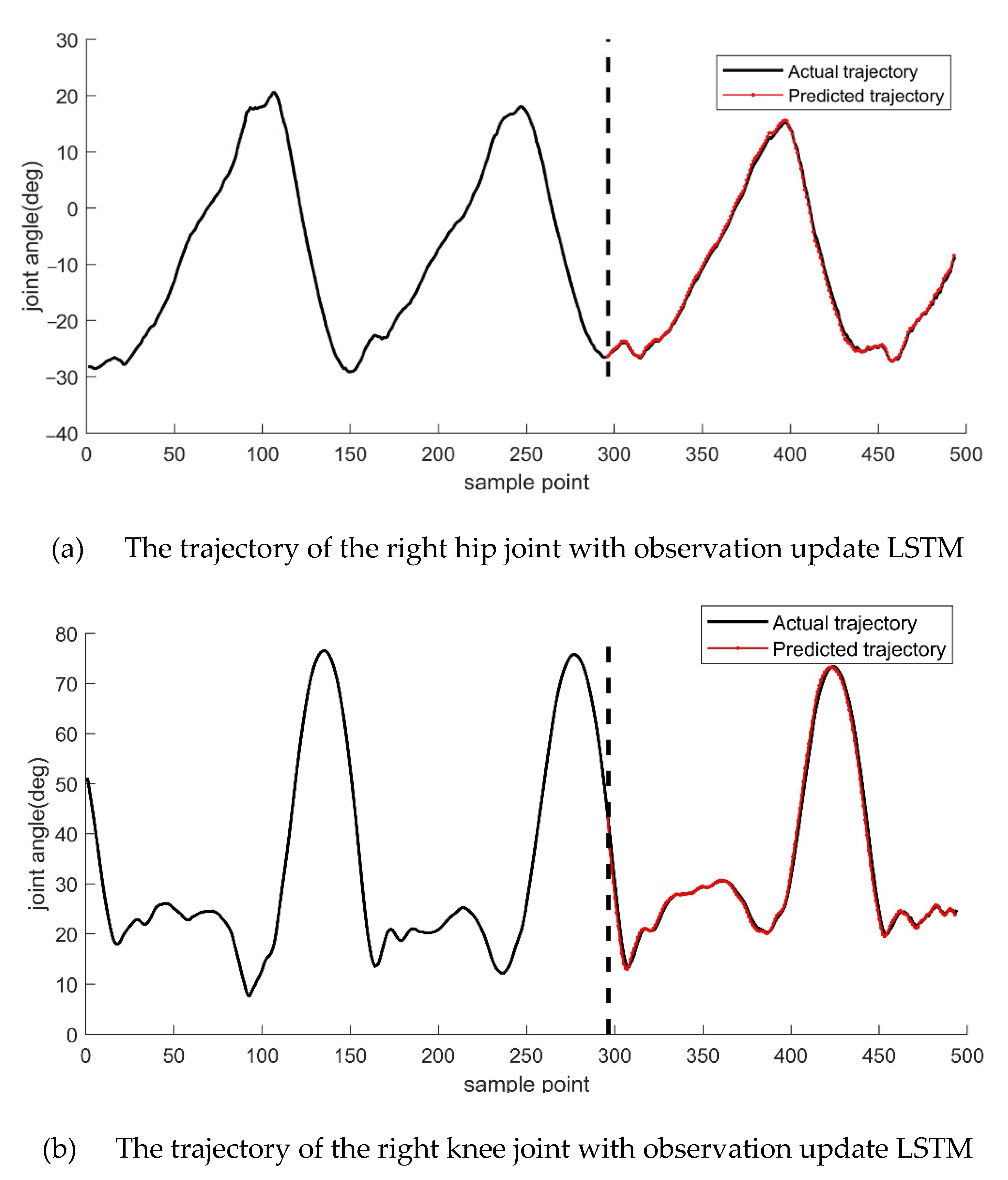
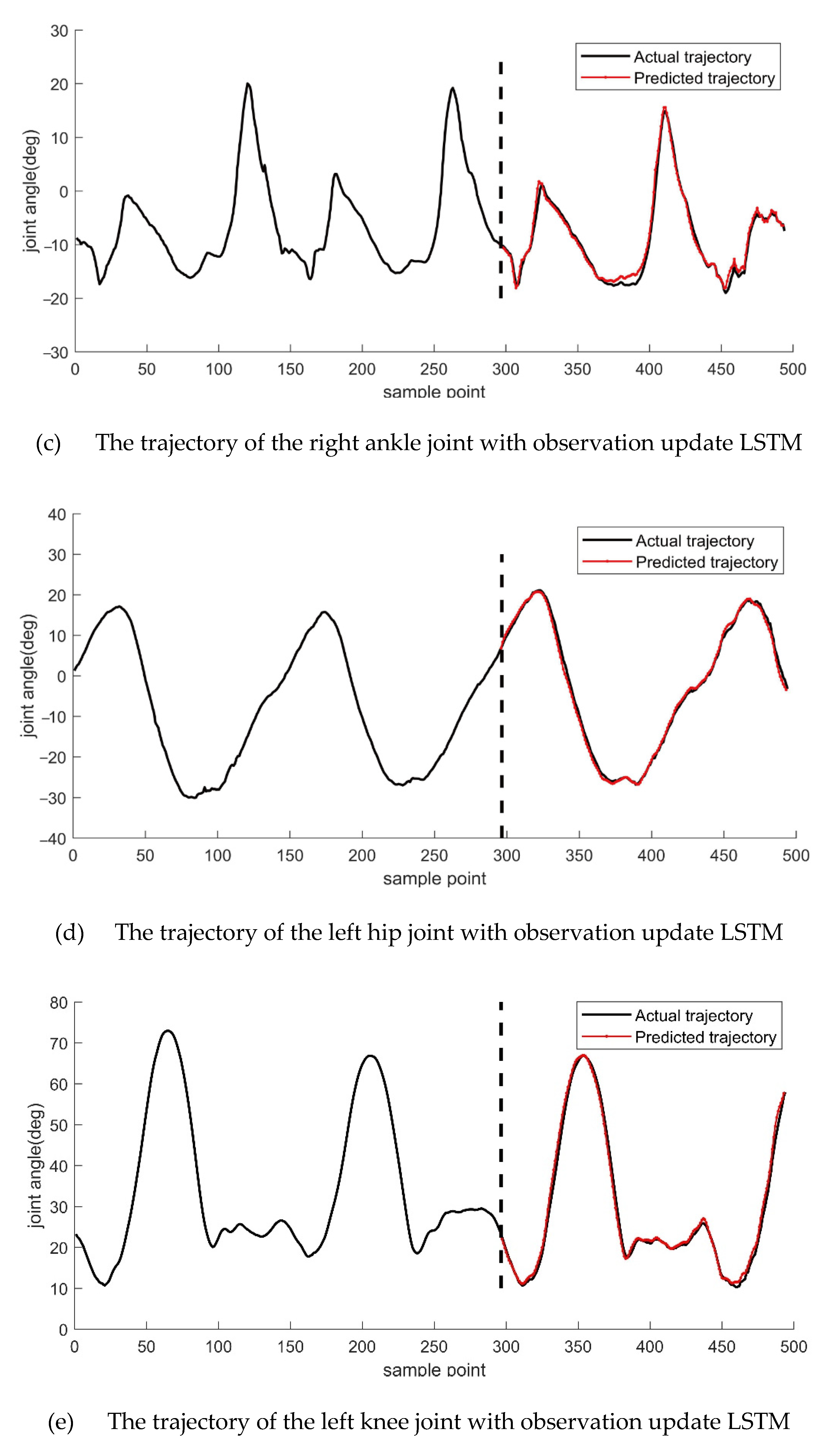
For the lower limb exoskeleton measurement device, which can obtain the motion trajectory data in real-time, we used the real-time signal (observation) from the sensor to update the LSTM so that the LSTM network could meet the demand of the real-time motion trajectory prediction better. The predicted results show in
Figure 4. From the top to the bottom, the trajectories of the right hip, right knee, right ankle, left hip, left knee, and left ankle are shown, respectively.
Two hundred fifty training iterations are performed in each round of computation. Although there will be slight changes in the results of each operation, it does not affect our evaluation of the two methods. From
Figure 4, we can observe that the motion trajectories of the left and right legs on both sides of the lower limb are better predicted at the hip, knee, and ankle joints. Compared to the conventional LSTM model, the LSTM model with real-time observations was more accurate in predicting the motion trajectory, and this can be seen in the results for the hip, knee, and ankle joints. To compare the prediction results with those of the conventional LSTM model, we calculated the root mean square error of the predicted trajectory against the actual trajectory for both sets of experiments, and the maximum and minimum values of the difference between the two were also calculated, as shown in
Table 1.
The analysis of the RMSE data of the table is available. The LSTM using an observation update prediction model was better than the Conventional LSTM prediction model.
The maximum error values in the conventional LSTM network were significantly larger than below. The RMSE also varies significantly. Regardless of the maximum error or the RMSE values, the conventional LSTM’s prediction accuracy for the gait trajectory was low. The prediction error of the knee joint was too large, making it undesirable to use the predicted trajectory to plan a dynamic exoskeleton.
In the observation-based update LSTM network, compared with conventional LSTM, there was a significant reduction in error maximum, error minimum, and evaluation factors such as root mean square error.
4. Experimental Verification
The gait trajectory prediction method of LSTM has been introduced above, and we used experiments to verify it.
(a) The wearable joint angle measurement device collects gait data and conducts collaborative control experiments with the lower limb exoskeleton measurement device.
(b) The wearable joint angle measurement device was used for gait data collection, and the LSTM prediction model was used for prediction and error analysis.
4.1. The Wearable Joint Angle Measurement Device
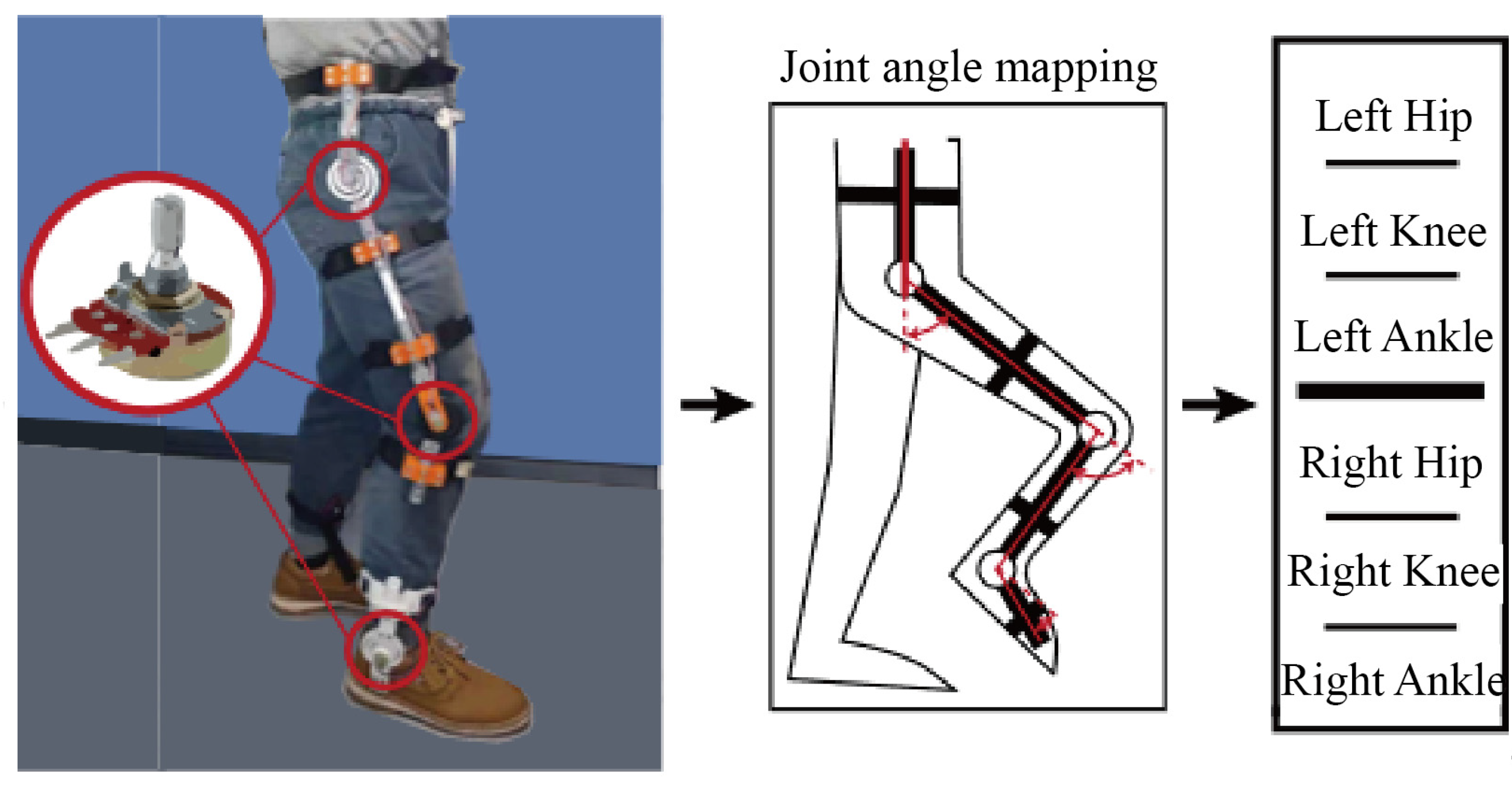
During the development and testing phase of the prototype, it was dangerous to strap the human body directly to the lower limb exoskeleton, even though it was possible to limit the position of the drive joint angle mechanically. Thus, we designed a wearable joint angle measurement device that has the same DOF configuration as the lower limb exoskeleton. The main components of the wearable joint angle measurement device include the hip measurement unit, the knee measurement unit, the ankle measurement unit, adjustable length thigh linkage, calf linkage, and shoes. The auxiliary components included the connections between the angle measuring units and the rods and shoes, the nylon bayonet straps, the signal wires, and the necessary connection terminals. The main movements of the human body during walking occurred in the flexion and extension of the hip, knee, and ankle joints. There was also a tiny amount of motion in each joint’s remaining degrees of freedom. We have developed a flexible spiral component to be mounted on the rotational output of the sensor, which can withstand a certain amount of bending moment while ensuring that the sensor can rotate to transmit the rotation angle of the physiological joint.
The sensor used in the measurement device is a rotating potentiometer (rotational range 0–210°) shown in the diagram, whose internal resistance changes in response to different rotational angles (0–10 k ohms). The measurement device only needs an external 5 V power to detect the sensor’s voltage signal.
In this equation, digit represents the converted numerical signal; R represents the resistance of the resistor, which is positively related to the angle θ of the potentiometer; R0 represents the resistance of the potentiometer at full range; VREF is the sensor reference voltage; and bit represents the number of bits of resolution of the analogue-to-digital converter, here in the sensing system as VREF = 5, bit = 10, R0 = 10 k.
The lower limb dimensions vary from person to person, and different wearers need to adjust the length of the linkage accordingly to ensure joint alignment. Therefore, to obtain a mapping relation between the sensor signals of the wearable joint angle measurement device and the actual physiological joint angles, the calibration process needs to be repeated at each time. After the Analogue to Digital Converter (ADC) has obtained the digital signal, the physiological joint angle is calculated by solving each joint angle’s reference in a specific posture.
The angle information of a total of 6 joints on both sides of the lower limbs on the sagittal plane was collected through the joint angle measuring device, including the right hip joint (RH), right knee joint (RK), right ankle joint (RA), left hip joint (LH), left knee joint (LK), and left ankle joint (LA). The collected data were recorded in the SD memory card by the microprocessor for offline data analysis.
4.2. Gait Data Collection and Analysis
The motion cooperation experiment was carried out as follows. First, the wearable joint angle measurement device was adjusted to the appropriate length for the subject’s thighs and lower legs to ensure that the rotational spindle of the rotary potentiometer was aligned with the central axis of rotation of the physiological joint. Because of the ingenious design of the wearable joint angle measurement device and the absence of a drive motor, the wearer can efficiently experiment by their usual activity habits.
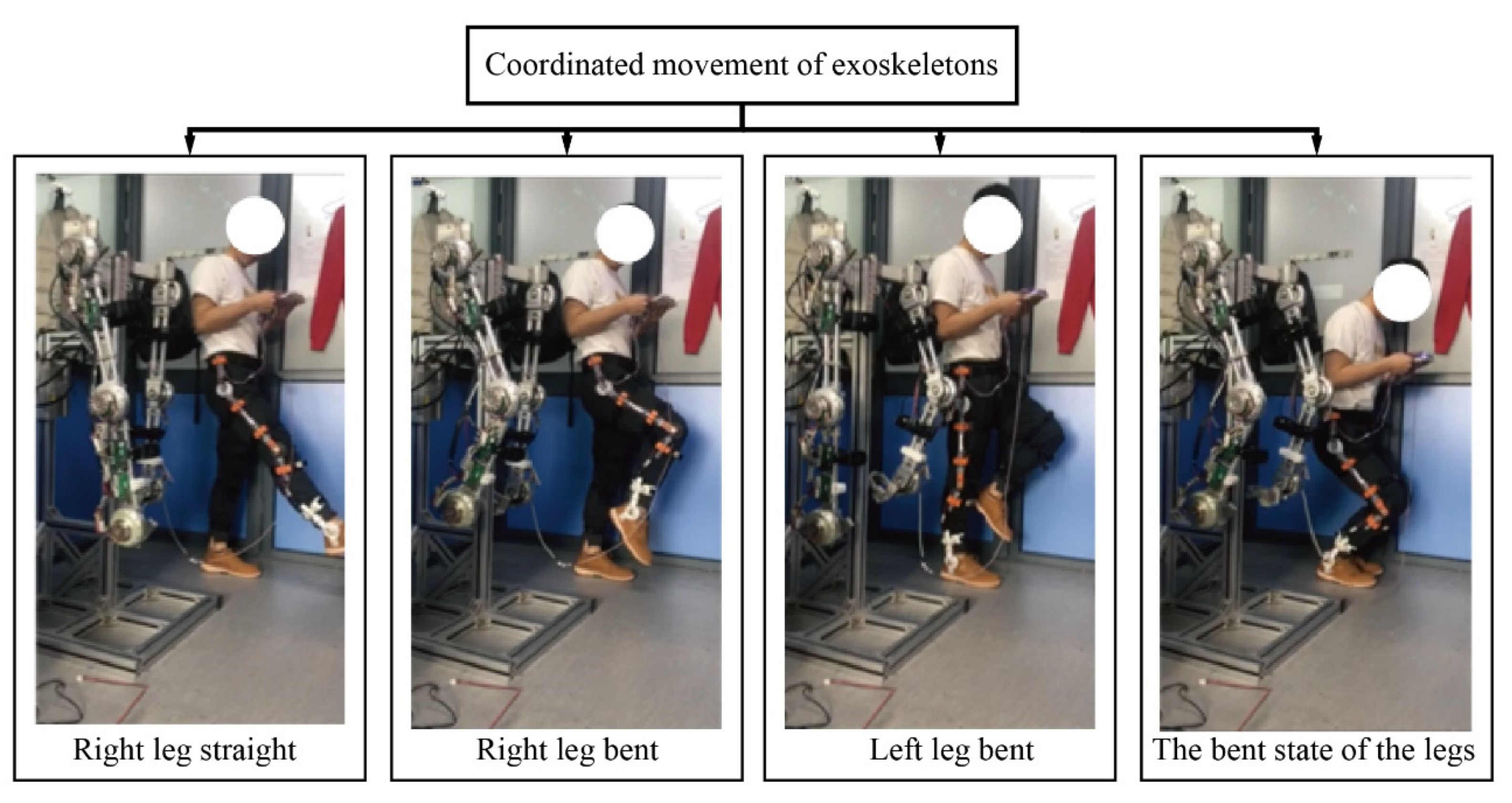
First, we carried out experiments in a laboratory environment and used an in situ stepping motion to represent the dynamic experiment of a walking motion.
Figure 5 shows the images of the dynamic exoskeleton and the subject’s coordinated movement under several different actions. From
Figure 5, it can be observed that the lower limb exoskeleton completely reproduced the human body’s lower limb movements, including one-leg forward extension, left and right knee joints, squatting movements, etc. These movements can entirely affect the six joints of the lower limbs.
In
Figure 6, the test subject did walk test in the same place. At first, the test subject was put on the joint angle measuring device and walked 80 m at a speed of 1 m/s. Then, The SD card in the wearable joint angle measurement device was equipped with a memory reader, and the angle change data during walking was recorded and stored. After collecting a set of data, data analysis was carried out. The Kalman filter algorithm processes the joint angle data to reduce the interference items in the data acquisition process [
22]. The LSTM prediction algorithm model trained and predicted the processed data. Finally, the processing results are as follows in
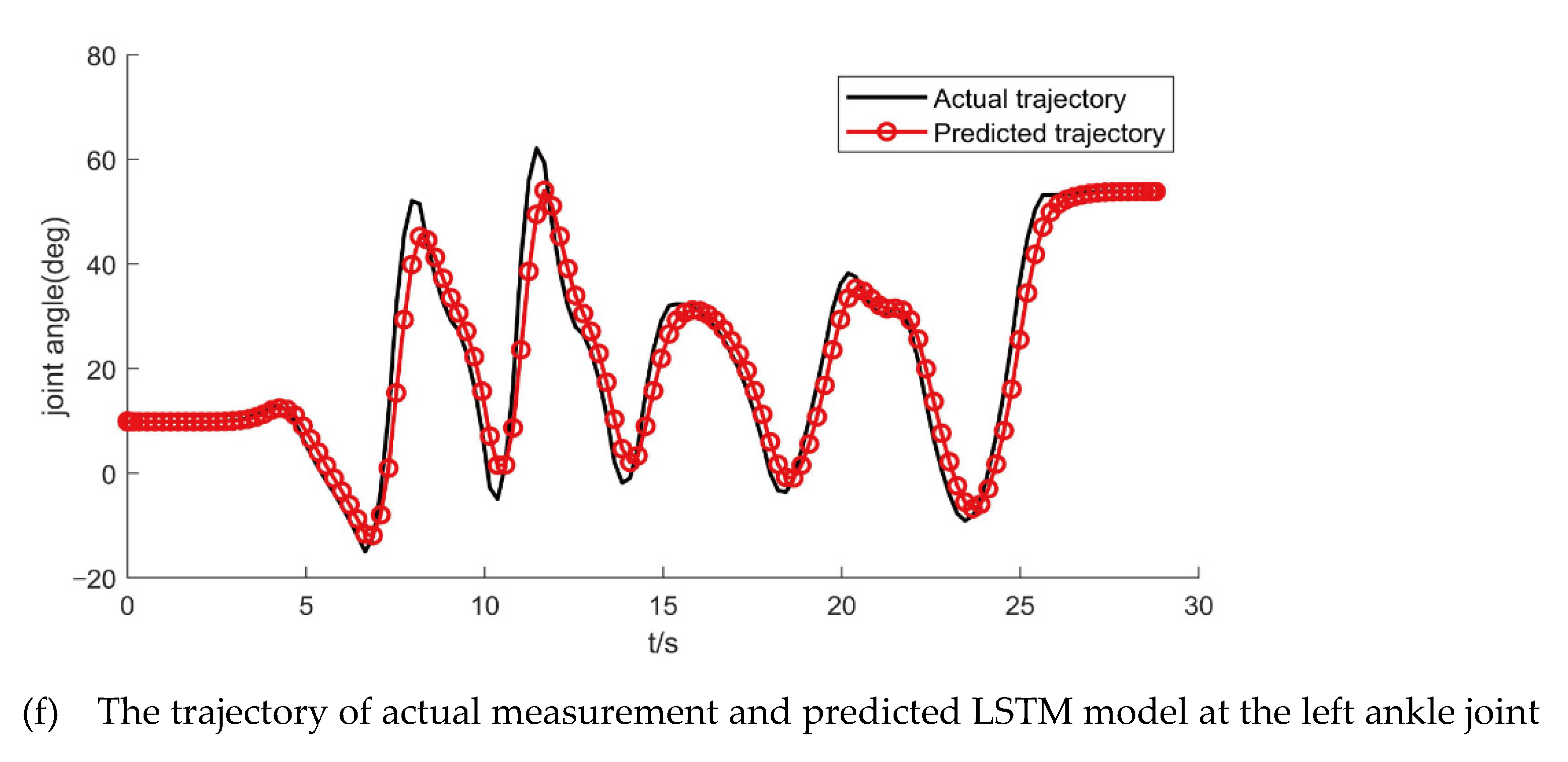
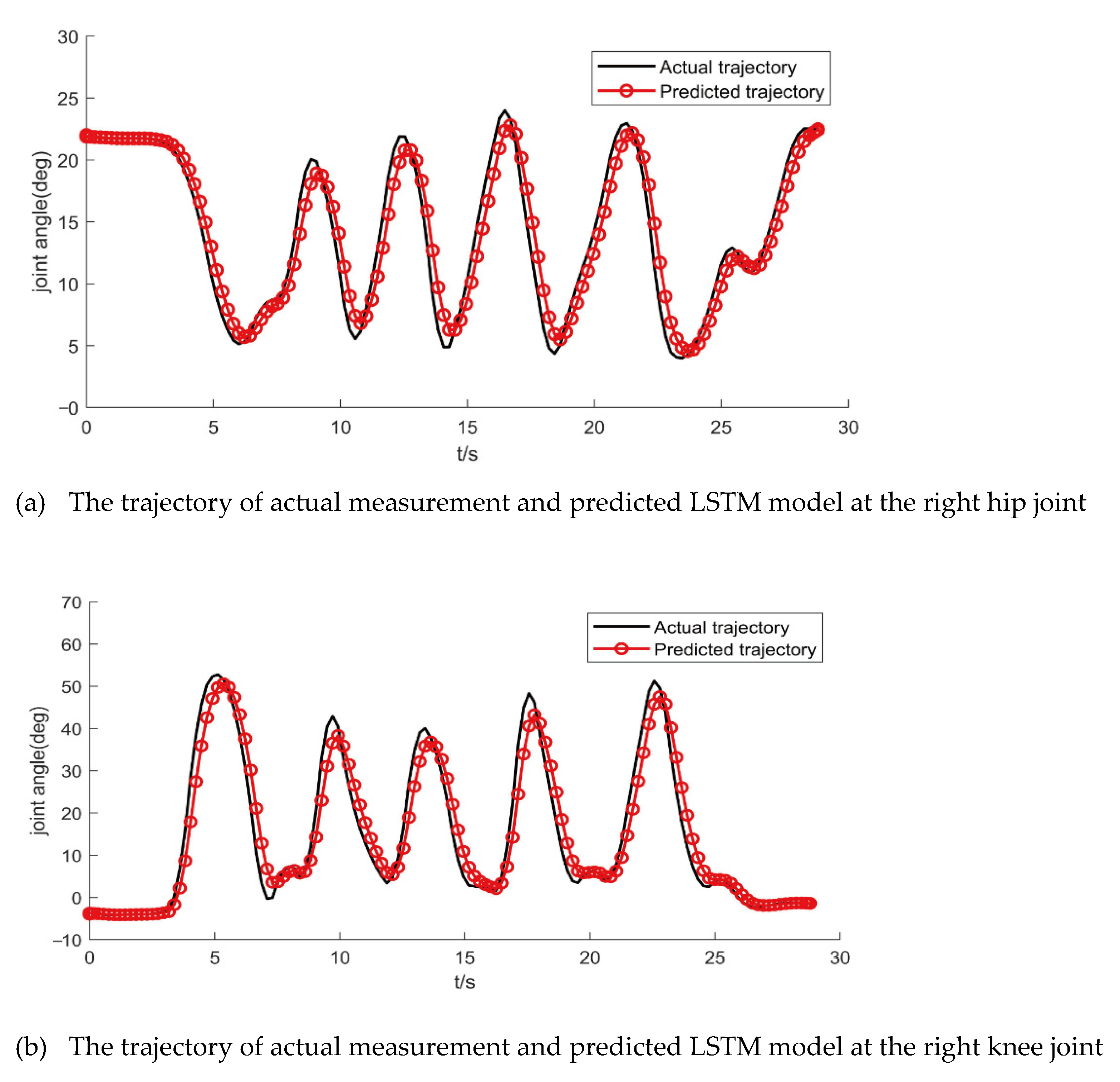
Figure 7.
The LSTM model used to predict the actual gait trajectory when the test subject put on wearable joint angle measurement device. In detail, we can obtain the prediction values of maximum error, minimum error, and RMSE of the actual trajectory with update observation LSTM model in
Table 2.
5. Conclusions
This paper used the LSTM prediction algorithm to predict the human gait and also used a wearable joint angle measurement device to verify the algorithm. Experimental results show:
(1) In the lower limb exoskeleton man–machine coupling system, the coordinated movement between the human body and the mechanical exoskeleton can be reliably sensed and recorded by the wearable joint angle measurement device. On the other hand, the recorded data can drive and control the power exoskeleton movement.
(2) On the one hand, using the LSTM prediction model can eliminate the complex process of establishing dynamic exoskeleton human–machine coupling kinematics and dynamics models. On the other hand, it can keep the gait prediction method active to deal with the subsequent actions that may change.
(3) The article uses the conventional LSTM prediction model and the LSTM using an observation update prediction model to predict and generate gait trajectories, which can provide predictions for the trajectory data of the power exoskeleton mechanical joints. In particular, the LSTM model that uses real-time updates of observations can more accurately predict the power movement trajectory of exoskeleton mechanical joints.
(4) In the LSTM prediction model, the RMSEs were: left hip joint 0.4662, right hip joint 0.4665, left knee joint 0.3246, right knee joint 0.5037, left ankle joint 0.7416, and right ankle joint 0.5548. The data show that the LSTM prediction algorithm has certain practical significance for predicting human gait data.
(5) The research results in this paper can be used for the gait trajectory planning of the human–machine cooperative movement of the lower extremity exoskeleton robot. Moreover, it can provide a reliable predictive gait reference trajectory for the lower limb exoskeleton so that the lower limb exoskeleton can perceive and plan the human–machine coupling system. Exercise provides a new idea for dynamic exoskeleton movement control.
In future, the experimental gait data collection should be performed in different complex environments, such as climbing stairs, going up and down in slope. Then, a variety of sensors data should be comprehensively considered for prediction. Finally, we could use physical information of the whole body to predict body posture for the development of exoskeleton suit.
Author Contributions
Conceptualization, B.R.; methodology, B.R. and Z.Z.; software, B.R. and Z.Z.; validation, B.R.; formal analysis, Z.Z.; investigation, B.R.; resources, B.R.; data curation, B.R. and Z.Z.; writing—original draft preparation, B.R. and Z.Z.; writing—review and editing, B.R.; visualization, S.C.; supervision, C.Z. and S.C.; project administration, C.Z. and S.C. All authors have read and agreed to the published version of the manuscript.
Funding
This research was funded by the Joint Funds of the National Natural Science Foundation of China (Grant No. U21A20121); National Natural Science Foundation of China (Grant No. 51775325); the National Key Research and Development Program of China (Grant No. 2018YFB1309200); and the Young Eastern Scholars Program of Shanghai (Grant No. QD2016033).
Institutional Review Board Statement
The study was conducted in accordance with the Declaration of Helsinki, and approved by the Ethics Committee of Shanghai University (protocol code ECSHU 2021-101 and 3 March 2021 of approval).
Informed Consent Statement
Informed consent was obtained from all subjects involved in the study.
Data Availability Statement
Not applicable.
Acknowledgments
The authors thank the laboratory students Jianwei Liu and Wanli Guan for their previous work on experiments data collection of lower limb exoskeleton and human body. They gave us the constructive suggestions for different control schemes.
Conflicts of Interest
The authors declare no conflict of interest.
References
- Dollar, A.M.; Herr, H. Lower extremity exoskeletons and active orthoses: Challenges and state-of-the-art. IEEE Trans. Robot. 2008, 24, 144–158. [Google Scholar] [CrossRef]
- Bogue, R. Robotic exoskeletons: A review of recent progress. Ind. Robot. Int. J. 2015, 42, 5–10. [Google Scholar] [CrossRef]
- Young, A.J.; Ferris, D. State of the Art and Future Directions for Lower Limb Robotic Exoskeletons. IEEE Trans. Neural Syst. Rehabil. Eng. 2017, 25, 171–182. [Google Scholar] [CrossRef] [PubMed]
- Bin Miskon, M.F.; Yusof, M.B.A.J. Review of Trajectory Generation of Exoskeleton Robots. In Proceedings of the IEEE International Symposium on Robotics and Manufacturing Automation (IEEE-ROMA), Kuala Lumpur, Malaysia, 15–16 December 2014; pp. 12–17. [Google Scholar]
- Glackin, C.; Salge, C.; Greaves, M.; Polani, D.; Slavnic, S.; Ristic-Durrant, D.; Leu, A.; Matjacic, Z. Gait Trajectory Prediction using Gaussian Process Ensembles. In Proceedings of the 14th IEEE-RAS International Conference on Humanoid Robots (Humanoids), Madrid, Spain, 18–20 November 2014; pp. 628–633. [Google Scholar]
- Su, B.; Gutierrez-Farewik, E.M. Gait Trajectory and Gait Phase Prediction Based on an LSTM Network. Sensors 2020, 20, 7127. [Google Scholar] [CrossRef] [PubMed]
- Kazerooni, H.; Racine, J.-L.; Huang, L.; Steger, R. On the control of the Berkeley Lower Extremity Exoskeleton (BLEEX). In Proceedings of the IEEE International Conference on Robotics and Automation (ICRA), Barcelona, Spain, 18–22 April 2005; pp. 4353–4360. [Google Scholar]
- Wu, G.; Wang, C.; Wu, X.; Wang, Z.; Ma, Y.; Zhang, T. Gait Phase Prediction for Lower Limb Exoskeleton Robots. In Proceedings of the IEEE International Conference on Information and Automation (ICIA), Ningbo, China, 1–3 August 2016; pp. 19–24. [Google Scholar]
- Ding, M.; Nagashima, M.; Cho, S.-G.; Takamatsu, J.; Ogasawara, T. Control of Walking Assist Exoskeleton With Time-delay Based on the Prediction of Plantar Force. IEEE Access 2020, 8, 138642–138651. [Google Scholar] [CrossRef]
- Wang, F.; Yin, T.; Lei, C.; Zhang, Y.; Wang, Y.; Liu, J. Prediction of Lower Limb Joint Angle using sEMG based on GA-GRNN. In Proceedings of the IEEE International Conference on Cyber Technology in Automation, Control, and Intelligent Systems (CYBER), Shenyang, China, 8–12 June 2015; pp. 1894–1899. [Google Scholar]
- Gao, F.; Liu, G.; Liang, F.; Liao, W.-H. IMU-Based Locomotion Mode Identification for Transtibial Prostheses, Orthoses, and Exoskeletons. IEEE Trans. Neural Syst. Rehabil. Eng. 2020, 28, 1334–1343. [Google Scholar] [CrossRef] [PubMed]
- Boudali, A.M.; Sinclair, P.J.; Manchester, I.R. Predicting Transitioning Walking Gaits: Hip and Knee Joint Trajectories From the Motion of Walking Canes. IEEE Trans. Neural Syst. Rehabil. Eng. 2019, 27, 1791–1800. [Google Scholar] [CrossRef] [PubMed]
- Vu, H.T.T.; Dong, D.; Cao, H.-L.; Verstraten, T.; Lefeber, D.; VanderBorght, B.; Geeroms, J. A Review of Gait Phase Detection Algorithms for Lower Limb Prostheses. Sensors 2020, 20, 3972. [Google Scholar] [CrossRef] [PubMed]
- Hong, J.; Chun, C.; Kim, S.-J.; Park, F.C. Gaussian Process Trajectory Learning and Synthesis of Individualized Gait Motions. IEEE Trans. Neural Syst. Rehabil. Eng. 2019, 27, 1236–1245. [Google Scholar] [CrossRef] [PubMed]
- Liu, D.-X.; Wu, X.; Du, W.; Wang, C.; Chen, C.; Xu, T. Deep Spatial-Temporal Model for rehabilitation gait: Optimal trajectory generation for knee joint of lower-limb exoskeleton. Assem. Autom. 2017, 37, 369–378. [Google Scholar] [CrossRef]
- Zaroug, A.; Lai, D.T.H.; Mudie, K.; Begg, R. Lower Limb Kinematics Trajectory Prediction Using Long Short-Term Memory Neural Networks. Front. Bioeng. Biotechnol. 2020, 8, 8. [Google Scholar] [CrossRef] [PubMed]
- Kidziński, Ł.; Delp, S.; Schwartz, M. Automatic real-time gait event detection in children using deep neural networks. PLoS ONE 2019, 14, e0211466. [Google Scholar]
- Jung, J.-Y.; Heo, W.; Yang, H.; Park, H. A Neural Network-Based Gait Phase Classification Method Using Sensors Equipped on Lower Limb Exoskeleton Robots. Sensors 2015, 15, 27738–27759. [Google Scholar] [CrossRef] [PubMed]
- Evans, R.; Arvind, D. Detection of Gait Phases Using Orient Specks for Mobile Clinical Gait Analysis. In Proceedings of the 11th International Conference on Wearable and Implantable Body Sensor Networks, Zurich, Switzerland, 16–19 June 2014; pp. 149–154. [Google Scholar]
- Liu, D.-X.; Wu, X.; Du, W.; Wang, C.; Xu, T. Gait Phase Recognition for Lower-Limb Exoskeleton with Only Joint Angular Sensors. Sensors 2016, 16, 1579. [Google Scholar] [CrossRef] [PubMed] [Green Version]
- Moreira, L.; Cerqueira, S.M.; Figueiredo, J.; Vilas-Boas, J.; Santos, C.P. AI-based Reference Ankle Joint Torque Trajectory Generation for Robotic Gait Assistance: First Steps. In Proceedings of the IEEE International Conference on Autonomous Robot Systems and Competitions (ICARSC), Univ Azores Campus, ELECTR NETWORK, Ponta Delgada, Portugal, 15–17 April 2020; pp. 22–27. [Google Scholar]
- Long, Y.; Du, Z.; Wang, W. Control and Experiment for Exoskeleton Robot Based on Kalman Prediction of Human Motion Intent. Robot 2015, 37, 304–309. [Google Scholar]
| Publisher’s Note: MDPI stays neutral with regard to jurisdictional claims in published maps and institutional affiliations. |
© 2022 by the authors. Licensee MDPI, Basel, Switzerland. This article is an open access article distributed under the terms and conditions of the Creative Commons Attribution (CC BY) license (https://creativecommons.org/licenses/by/4.0/).


