
A Soft Electro-Hydraulic Pneumatic Actuator with Self-Sensing Capability toward Multi-Modal Haptic Feedback

 ,
,  ,
,  , , ,
, , , 
Abstract
:1. Introduction
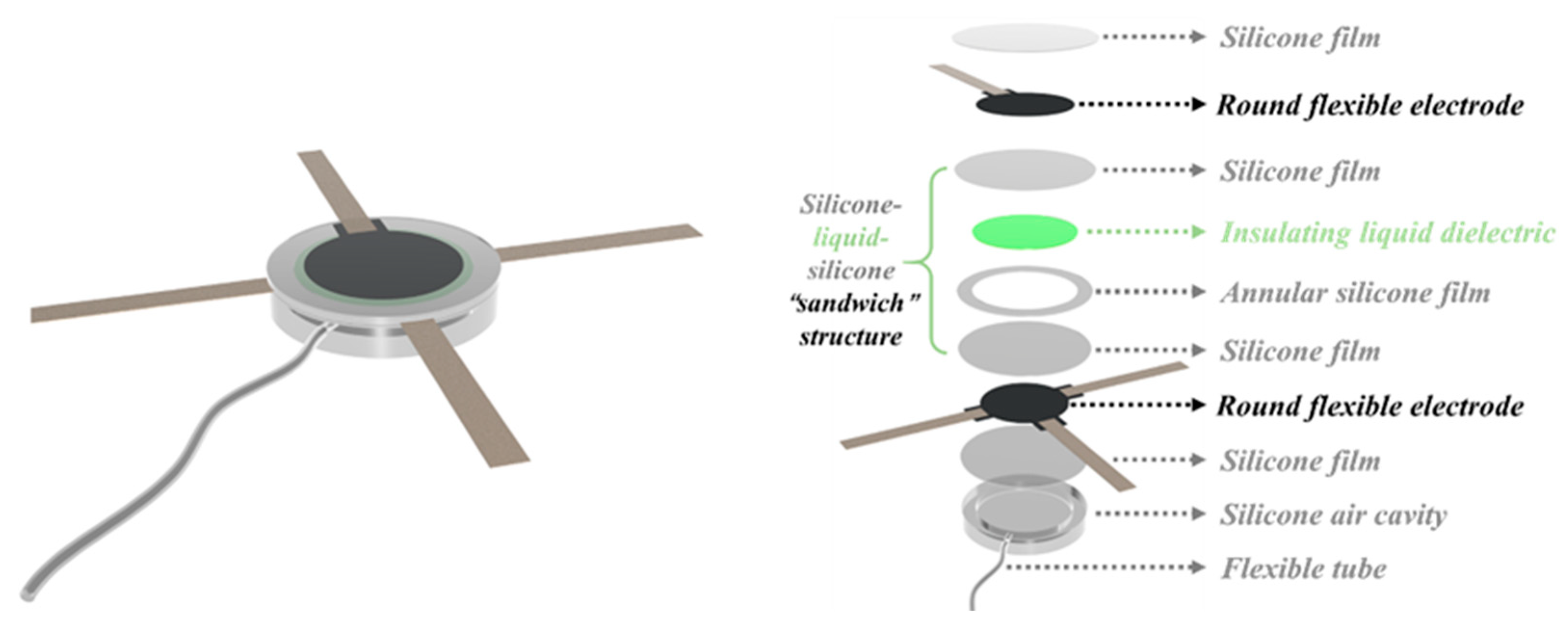
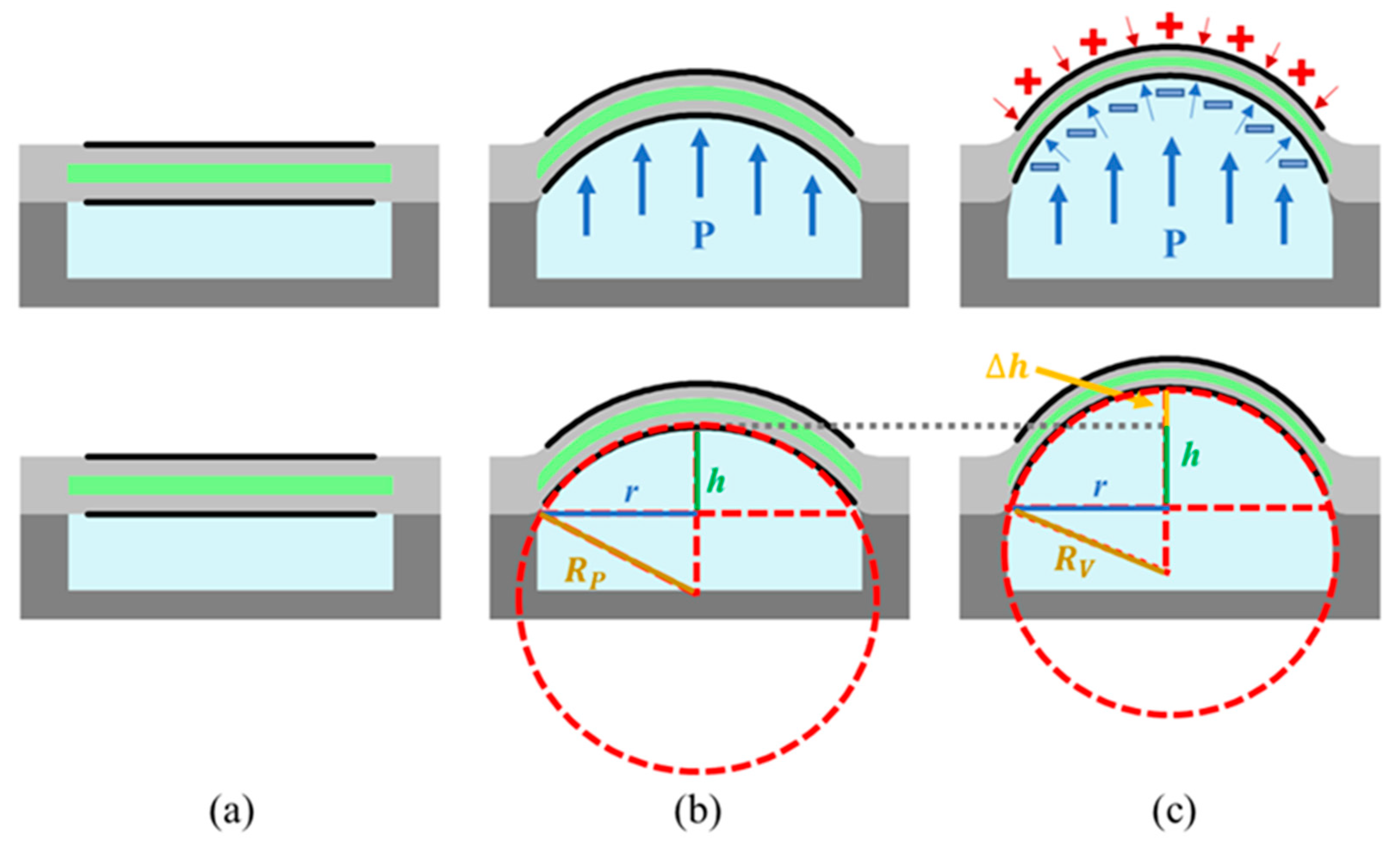
2. Design
3. Materials and Methods
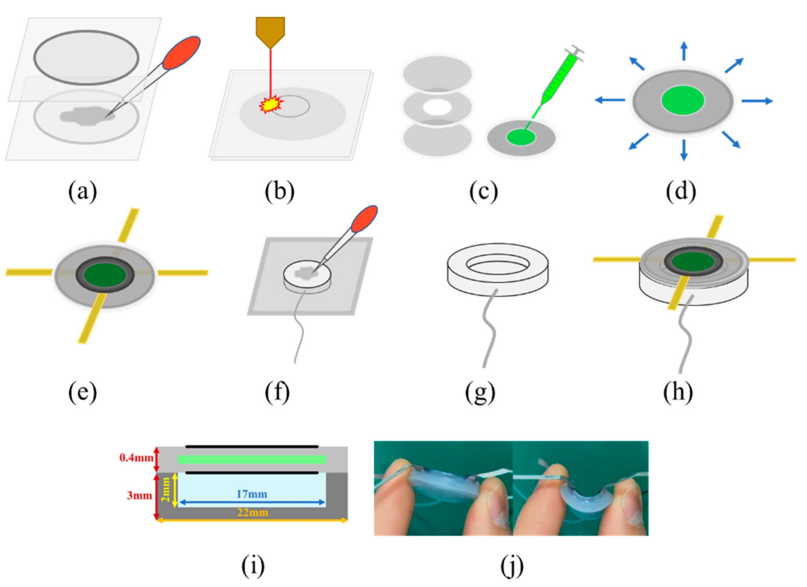
3.1. Fabrication
3.2. Test Methods
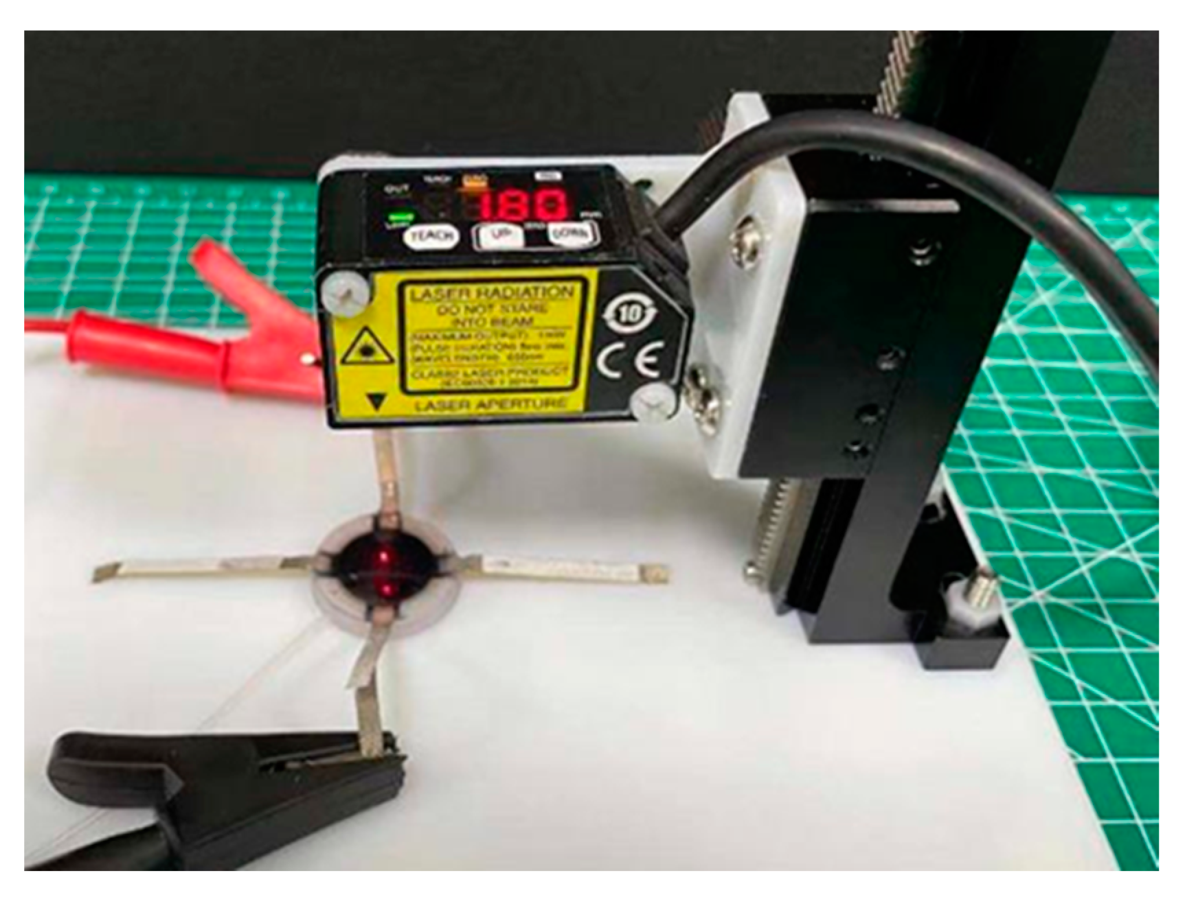
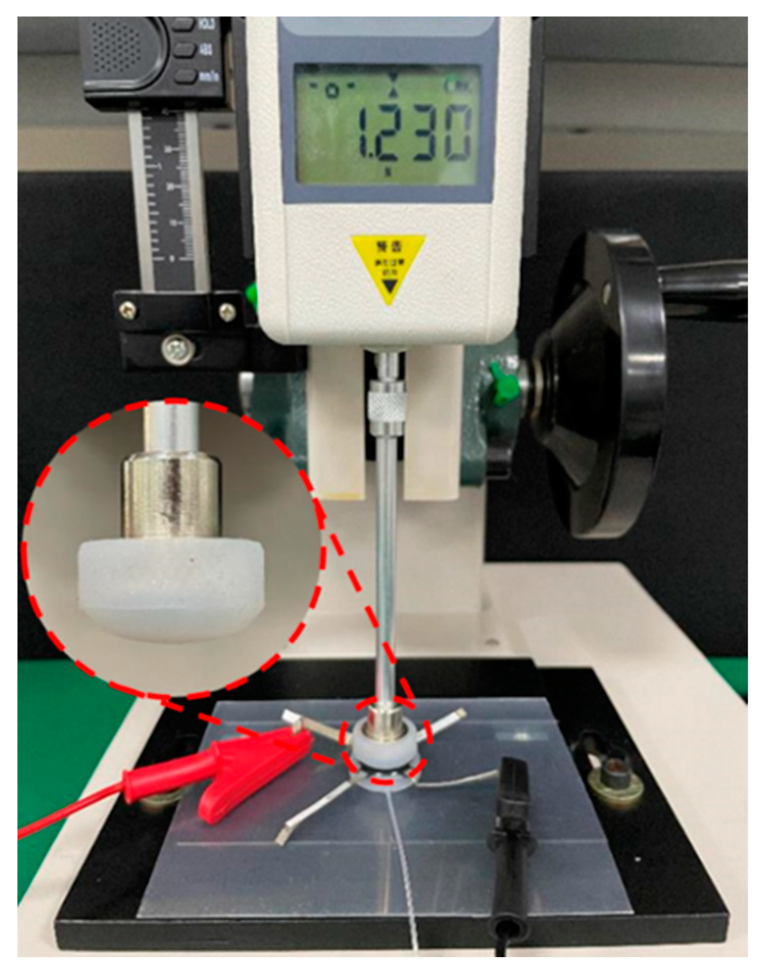
3.2.1. Output Displacement Measurement
3.2.2. Output Force Measurement
3.2.3. Resistance Measurement
4. Results
4.1. Output Performance of SEHPA
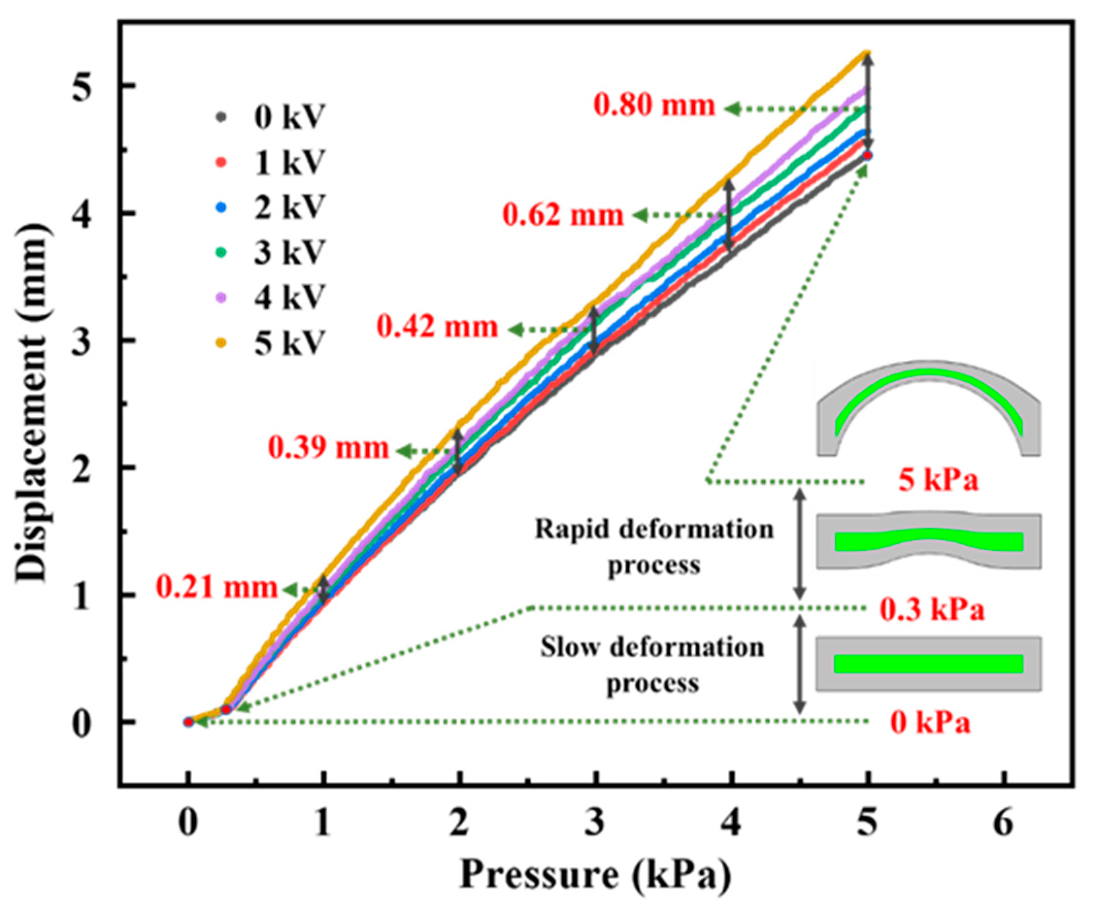
4.1.1. Output Displacement of SEHPA
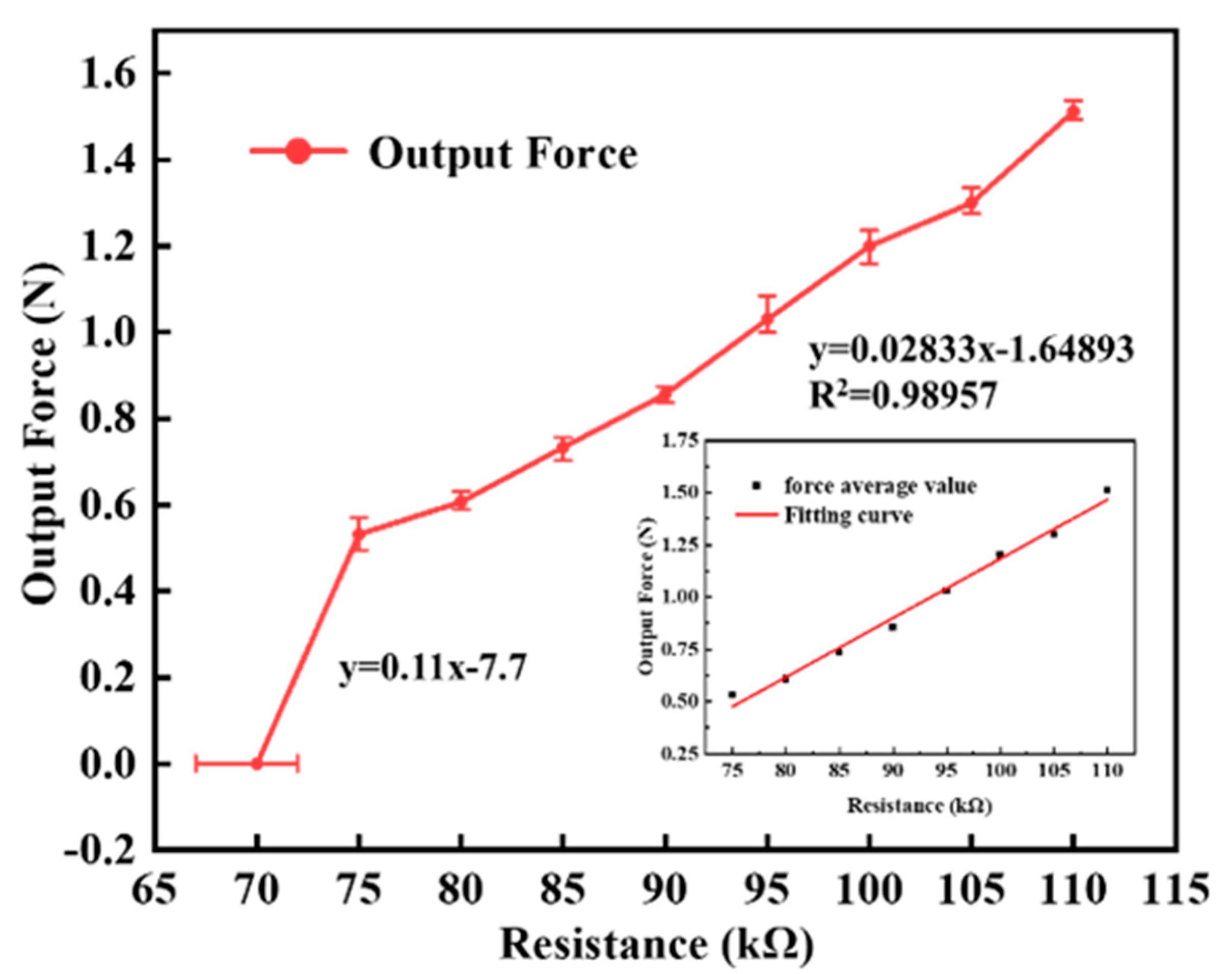
4.1.2. Output Force of SEHPA
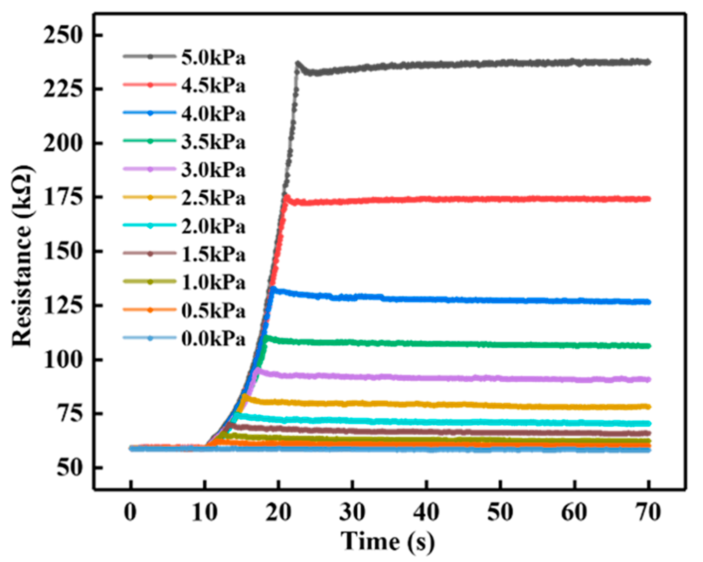
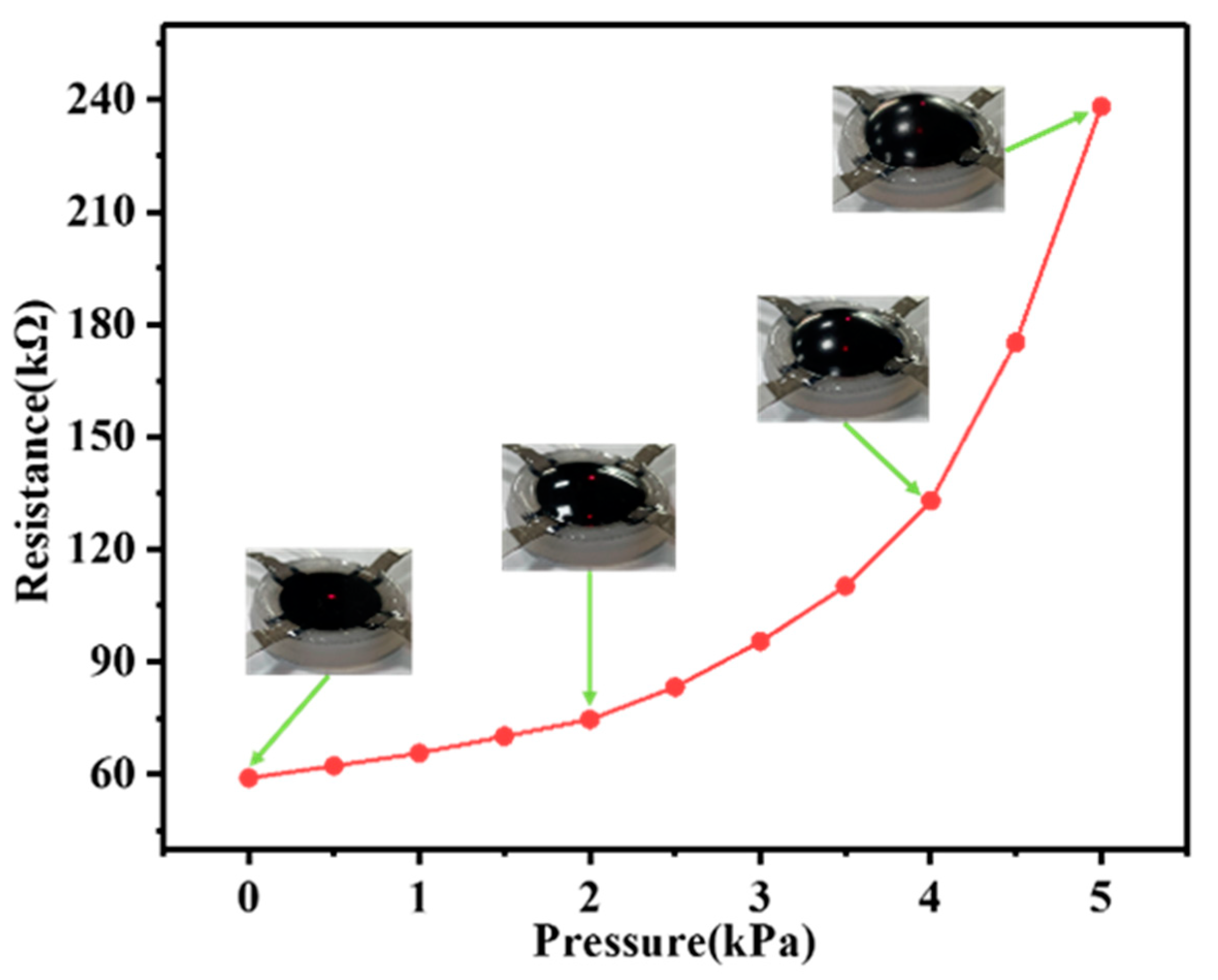
4.1.3. Self-Sensing Capability of SEHPA
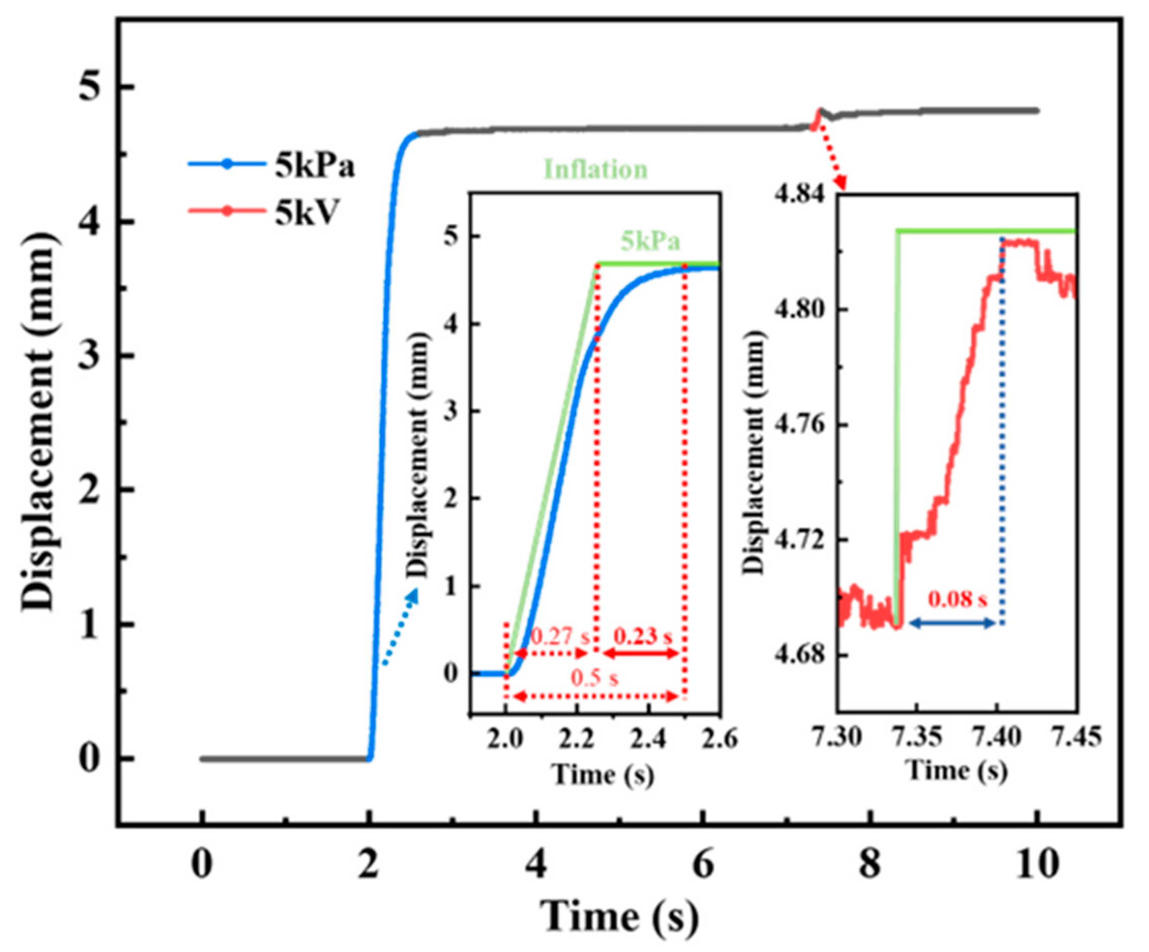
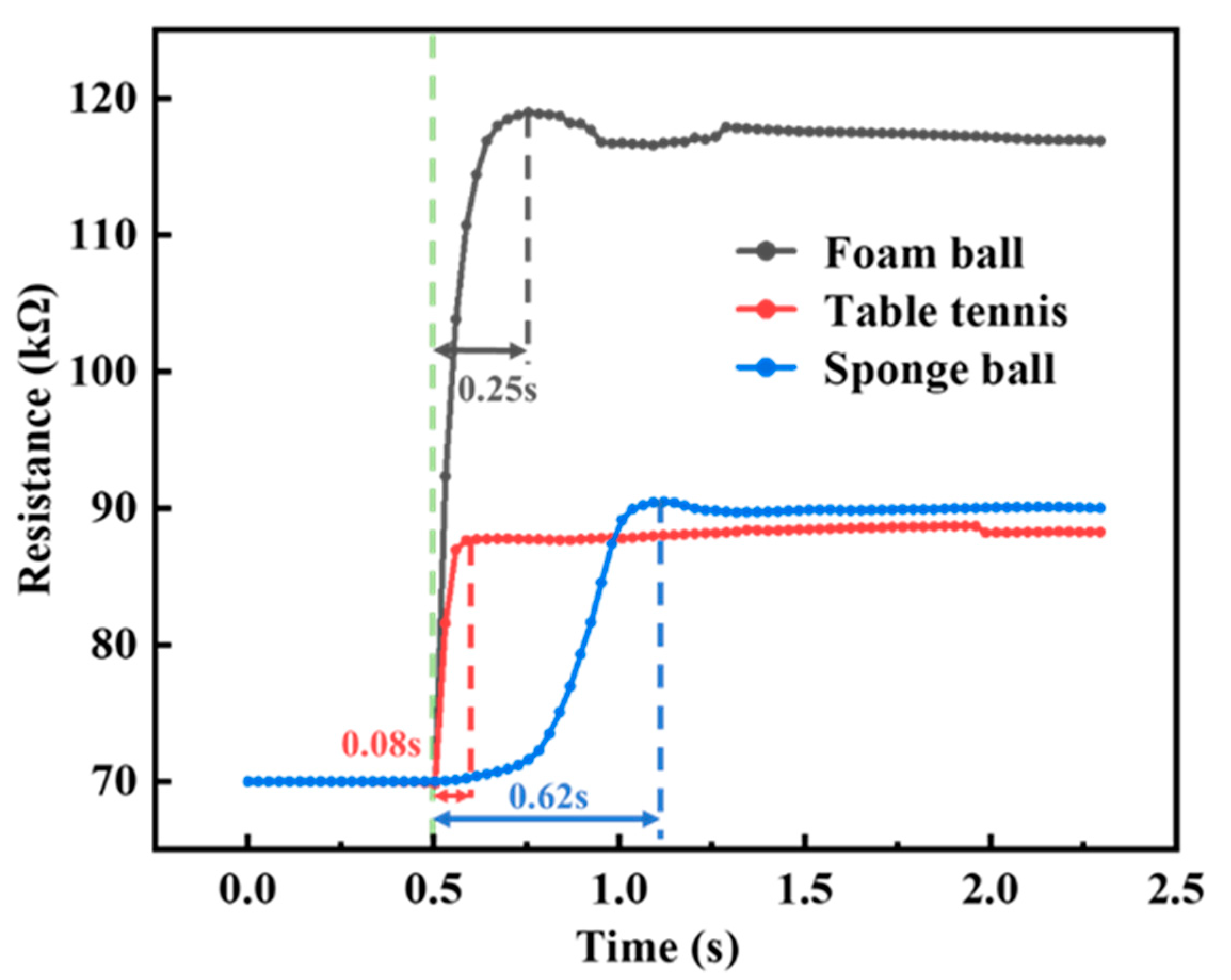
4.1.4. The Response Time of SEHPA
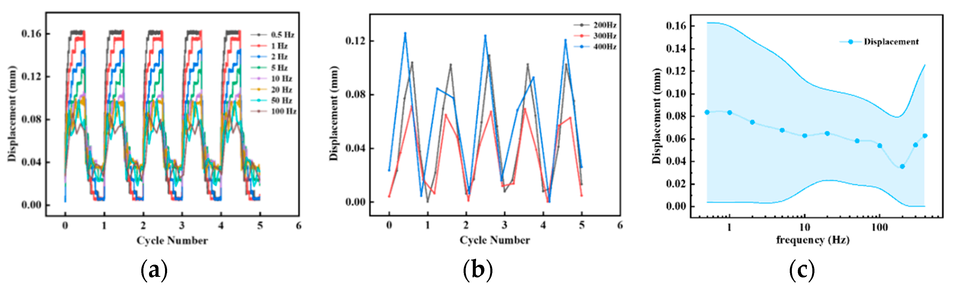
4.1.5. The Vibration of SEHPA
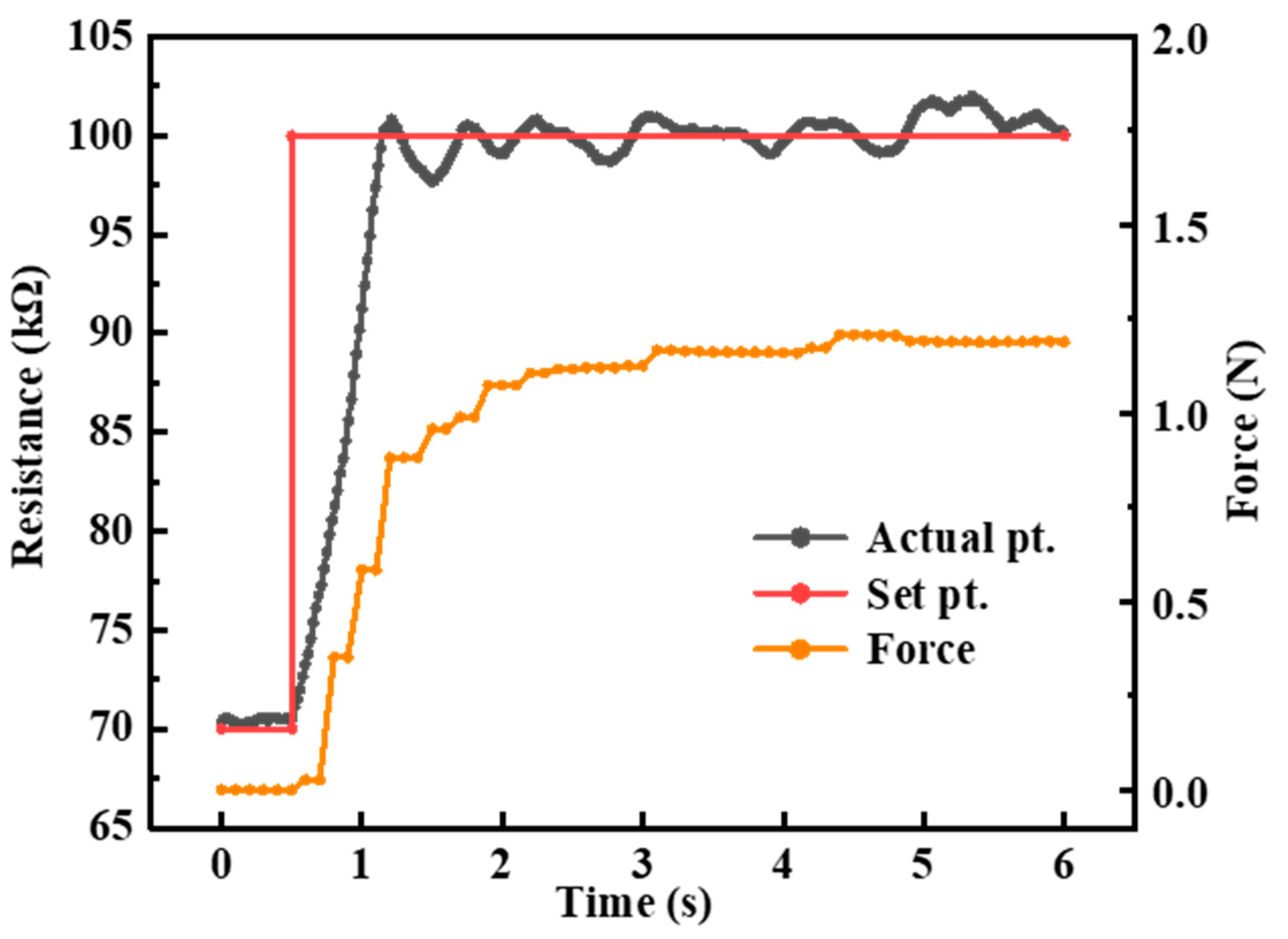
4.2. Self-Sensing Closed-Loop Control of SEHPA
4.3. Application of SEHPA
4.3.1. Synchronous Haptic Feedback
4.3.2. Application of Haptic Notifications
5. Conclusions
Supplementary Materials
Author Contributions
Funding
Institutional Review Board Statement
Informed Consent Statement
Data Availability Statement
Conflicts of Interest
References
- Yu, X.; Xie, Z.; Yu, Y.; Lee, J.; Vazquez-Guardado, A.; Luan, H.; Ruban, J.; Ning, X.; Akhtar, A.; Li, D.; et al. Skin-integrated wireless haptic interfaces for virtual and augmented reality. Nature 2019, 575, 473–479. [Google Scholar] [CrossRef] [PubMed]
- Gallo, S.; Son, C.; Lee, H.J.; Bleuler, H.; Cho, I.-J. A flexible multimodal tactile display for delivering shape and material information. Sens. Actuators A-Phys. 2015, 236, 180–189. [Google Scholar] [CrossRef]
- Kappassov, Z.; Corrales, J.-A.; Perdereau, V. Tactile sensing in dexterous robot hands-Review. Robot. Auton. Syst. 2015, 74, 195–220. [Google Scholar] [CrossRef] [Green Version]
- Kim, Y.; Cha, J.; Ryu, J.; Oakley, I. A Tactile Glove Design and Authoring System for Immersive Multimedia. IEEE Multimed. 2009, 17, 34–44. [Google Scholar] [CrossRef]
- Sarakoglou, I.; Garcia-Hernandez, N.; Tsagarakis, N.G.; Caldwell, D.G. A high performance tactile feedback display and its integration in teleoperation. IEEE Trans. Haptics 2012, 5, 252–263. [Google Scholar] [CrossRef]
- Bianchi, M.; Battaglia, E.; Poggiani, M.; Ciotti, S.; Bicchi, A. A wearable fabric-based display for haptic multi-cue delivery. In Proceedings of the 24th IEEE Haptics Symposium, Philadelphia, PA, USA, 8–11 April 2016; pp. 277–283. [Google Scholar]
- Gu, W.; Zhu, X.; Futai, N.; Cho, B.S.; Takayama, S. Computerized microfluidic cell culture using elastomeric channels and Braille displays. Proc. Natl. Acad. Sci. USA 2004, 101, 15861–15866. [Google Scholar] [CrossRef] [Green Version]
- Lv, J.-A.; Liu, Y.; Wei, J.; Chen, E.; Qin, L.; Yu, Y. Photocontrol of fluid slugs in liquid crystal polymer microactuators. Nature 2016, 537, 179–184. [Google Scholar] [CrossRef] [PubMed]
- Gorissen, B.; Reynaerts, D.; Konishi, S.; Yoshida, K.; Kim, J.-W.; Volder, M.D. Elastic inflatable actuators for soft robotic applications. Adv. Mater. 2017, 29, 1604977. [Google Scholar] [CrossRef] [PubMed]
- Tang, S.-Y.; Zhang, X.; Sun, S.; Yuan, D.; Zhao, Q.; Yan, S.; Deng, L.; Yun, G.; Zhang, J.; Zhang, S.; et al. Versatile microfluidic platforms enabled by novel magnetorheological elastomer microactuators. Adv. Funct. Mater. 2018, 28, 1705484. [Google Scholar] [CrossRef] [Green Version]
- Liu, Q.; Zhan, Y.; Wei, J.; Ji, W.; Hu, W.; Yu, Y. Dual-responsive deformation of a crosslinked liquid crystal polymer film with complex molecular alignment. Soft Matter 2017, 13, 6145–6151. [Google Scholar] [CrossRef]
- Takagi, K.; Kitazaki, Y.; Kondo, K. A Simple Dynamic Characterization Method for Thin Stacked Dielectric Elastomer Actuators by Suspending a Weight in Air and Electrical Excitation. Actuators 2021, 10, 40. [Google Scholar] [CrossRef]
- Rothemund, P.; Kellaris, N.; Mitchell, S.K.; Acome, E.; Keplinger, C. HASEL Artificial Muscles for a New Generation of Lifelike Robots-Recent Progress and Future Opportunities. Adv. Mater. 2021, 33, 2003375. [Google Scholar] [CrossRef] [PubMed]
- Tang, W.; Lin, Y.; Zhang, C.; Liang, Y.; Wang, J.; Wang, W.; Ji, C.; Zhou, M.; Yang, H.; Zou, J. Self-contained soft electrofluidic actuators. Sci. Adv. 2021, 7, eabf8080. [Google Scholar] [CrossRef] [PubMed]
- Lee, E.-H.; Kim, S.-H.; Yun, K.-S. Three-Axis Pneumatic Haptic Display for the Mechanical and Thermal Stimulation of a Human Finger Pad. Actuators 2021, 10, 60. [Google Scholar] [CrossRef]
- Li, M.; Luo, S.; Nanayakkara, T.; Seneviratne, L.D.; Dasgupta, P.; Althoefer, K. Multi-fingered haptic palpation using pneumatic feedback actuators. Sens. Actuators A Phys. 2014, 218, 132–141. [Google Scholar] [CrossRef]
- Song, K.; Kim, S.H.; Jin, S.; Kim, S.; Lee, S.; Kim, J.-S.; Park, J.-M.; Cha, Y. Pneumatic actuator and flexible piezoelectric sensor for soft virtual reality glove system. Sci. Rep. 2019, 9, 8988. [Google Scholar] [CrossRef] [Green Version]
- Uramune, R.; Ishizuka, H.; Hiraki, T.; Kawahara, Y.; Ikeda, S.; Oshiro, O. HaPouch: Soft and Wearable Haptic Display Devices using Liquid-to-gas Phase Change Actuator. In Proceedings of the 33rd Annual ACM Symposium on User Interface Software and Technology, New York, NY, USA, 20–23 October 2020; pp. 53–55. [Google Scholar] [CrossRef]
- Frediani, G.; Boys, H.; Ghilardi, M.; Poslad, S.; Busfield, J.J.C.; Carpi, F. A Soft Touch: Wearable Tactile Display of Softness Made of Electroactive Elastomers. Adv. Mater. Technol. 2021, 6, 16. [Google Scholar] [CrossRef]
- Leroy, E.; Hinchet, R.; Shea, H. Multimode Hydraulically Amplified Electrostatic Actuators for Wearable Haptics. Adv. Mater. 2020, 32, 2002564. [Google Scholar] [CrossRef]
- Koo, I.M.; Jung, K.; Koo, J.C.; Nam, J.-D.; Lee, Y.K.; Choi, H.R. Development of soft-actuator-based wearable tactile display. IEEE Trans. Robot. 2008, 24, 549–558. [Google Scholar] [CrossRef]
- Chakraborti, P.; Karahan Toprakci, H.A.; Yang, P.; Di Spigna, N.; Franzon, P.; Ghosh, T. A compact dielectric elastomer tubular actuator for refreshable Braille displays. Sens. Actuators A Phys. 2012, 179, 151–157. [Google Scholar] [CrossRef]
- Sonar, H.A.; Gerratt, A.P.; Lacour, S.P.; Paik, J. Closed-loop haptic feedback control using a self-sensing soft pneumatic actuator skin. Soft Robot. 2020, 7, 22–29. [Google Scholar] [CrossRef] [PubMed]
- Joshi, S.; Sonar, H.; Paik, J. Flow path optimization for soft pneumatic actuators: Towards optimal performance and portability. IEEE Robot. Autom. Lett. 2021, 6, 7949–7956. [Google Scholar] [CrossRef]
- Sparks, J.L.; Vavalle, N.A.; Kasting, K.E.; Long, B.; Tanaka, M.L.; Sanger, P.A.; Schnell, K.; Conner-Kerr, T.A. Use of Silicone Materials to Simulate Tissue Biomechanics as Related to Deep Tissue Injury. Adv. Ski. Wound Care 2015, 28, 59–68. [Google Scholar] [CrossRef] [PubMed]
- Grushko, S.; Vysock, A.; Oscadal, P.; Vocetka, M.; Novak, P.; Bobovsky, Z. Improved Mutual Understanding for Human-Robot Collaboration: Combining Human-Aware Motion Planning with Haptic Feedback Devices for Communicating Planned Trajectory. Sensors 2021, 21, 3673. [Google Scholar] [CrossRef] [PubMed]
- Acome, E.; Mitchell, S.K.; Morrissey, T.G.; Emmett, M.B.; Benjamin, C.; King, M.; Radakovitz, M.; Keplinger, C. Hydraulically amplified self-healing electrostatic actuators with muscle-like performance. Science 2018, 359, 61–65. [Google Scholar] [CrossRef] [Green Version]
- Kellaris, N.; Venkata, V.G.; Rothemund, P.; Keplinger, C. An analytical model for the design of Peano-HASEL actuators with drastically improved performance. Extrem. Mech. Lett. 2019, 29, 100449. [Google Scholar] [CrossRef]
- Guo, W.; Wang, X.; Lu, X.; Li, X.; Li, Y.; Sun, J. Plant oil and amino acid-derived elastomers with rapid room temperature self-healing ability. J. Mater. Chem. A 2019, 7, 21927–21933. [Google Scholar] [CrossRef]
- Chang, W.; Kanda, H.; Ikeda, R.; Ling, J.; DeBerry, J.J.; Gu, J.G. Merkel disc is a serotonergic synapse in the epidermis for transmitting tactile signals in mammals. Proc. Natl. Acad. Sci. USA 2016, 113, E5491–E5500. [Google Scholar] [CrossRef] [Green Version]
- Huang, P.; Cao, Y.; Wei, Y.; Cheng, X.; Liu, J.; Zhang, S.; Wang, P.; Chen, S.; Xia, Z. Anisotropic Printed Resistor with Linear Sensitivity Based on Nano–Microfiller-Filled Polymer Composite. Adv. Electron. Mater. 2021, 7, 2100581. [Google Scholar] [CrossRef]
- Huang, P.; Xia, Z.; Cui, S. 3D printing of carbon fiber-filled conductive silicon rubber. Mater. Des. 2018, 142, 11–21. [Google Scholar] [CrossRef]


Publisher’s Note: MDPI stays neutral with regard to jurisdictional claims in published maps and institutional affiliations. |
© 2022 by the authors. Licensee MDPI, Basel, Switzerland. This article is an open access article distributed under the terms and conditions of the Creative Commons Attribution (CC BY) license (https://creativecommons.org/licenses/by/4.0/).
Share and Cite
Wang, H.; Cheng, X.; Huang, P.; Yu, M.; Ma, J.; Peng, S.; Cheng, Y.; Yu, Y.; Yang, W.; Wang, P.; et al. A Soft Electro-Hydraulic Pneumatic Actuator with Self-Sensing Capability toward Multi-Modal Haptic Feedback. Actuators 2022, 11, 74. https://doi.org/10.3390/act11030074
Wang H, Cheng X, Huang P, Yu M, Ma J, Peng S, Cheng Y, Yu Y, Yang W, Wang P, et al. A Soft Electro-Hydraulic Pneumatic Actuator with Self-Sensing Capability toward Multi-Modal Haptic Feedback. Actuators. 2022; 11(3):74. https://doi.org/10.3390/act11030074
Chicago/Turabian StyleWang, Haoyu, Xiang Cheng, Pei Huang, Meng Yu, Jiaqi Ma, Shigang Peng, Yue Cheng, Yuan Yu, Weimin Yang, Pengfei Wang, and et al. 2022. "A Soft Electro-Hydraulic Pneumatic Actuator with Self-Sensing Capability toward Multi-Modal Haptic Feedback" Actuators 11, no. 3: 74. https://doi.org/10.3390/act11030074
APA StyleWang, H., Cheng, X., Huang, P., Yu, M., Ma, J., Peng, S., Cheng, Y., Yu, Y., Yang, W., Wang, P., & Jiao, Z. (2022). A Soft Electro-Hydraulic Pneumatic Actuator with Self-Sensing Capability toward Multi-Modal Haptic Feedback. Actuators, 11(3), 74. https://doi.org/10.3390/act11030074