Abstract
The agricultural sector is constantly evolving. The rise in the world’s population generates an increasingly growing demand for food, resulting in the need for the agroindustry to meet this demand. Tractors are the vehicles that have made a real difference in agriculture’s development throughout history, lowering costs in soil tillage and facilitating activities and operations for workers. This study aims to successfully design and build an autonomous, electric agricultural tractor that can autonomously perform recurring tasks in open-field and greenhouse applications. This project is fully part of the new industrial and agronomic revolution, known as Factory 4.0 and Agriculture 4.0. The predetermined functional requirements for the vehicle are its lightweight, accessible price, the easy availability of its spare parts, and its simple, ordinary maintenance. In this first study, the preliminary phases of sizing and conceptual design of the rover are reported before subsequently proceeding to the dynamical analysis. To optimize the design of the various versions of the automated vehicle, it is decided that a standard chassis would be built based on a robot operating inside a greenhouse on soft and flat terrains. The SimScape multi-body environment is used to model the kinematics of the non-back-drivable screw jack mechanism for the hitch-lifting arms. The control unit for the force exerted is designed and analyzed by means of an inverse dynamics simulation to evaluate the force and electric power consumed by the actuators. The results obtained from the analysis are essential for the final design of the autonomous electric tractor.
1. Introduction
In the course of human history, there has been an evolution in agricultural production concerning yield, endurance, and requirements [1,2]. Throughout the centuries, humankind always has looked for various types of alternative energy sources for farming activities; suffice it to say that the sector only started relying on human and animal power a century ago [3]. The first tractors and farming machines were introduced only in vast areas due to the high costs of the new technology. Nevertheless, the mass production of tractors and machines allowed for such tools to be accessible to small land owners [4]. Moreover, advancements in electronics and automatism resulted in a milestone that fostered the development and production of automated self-driving vehicles [5]. This study aims to design and develop an autonomous electric tractor capable of performing activities both in the open field and in greenhouses [6,7,8]. Agriculture 4.0 is the systematic use of innovative technologies, and the utilization of electric vehicles is an integral part of it [9,10,11]. Currently, many companies are developing technologies and actual models that fit the perspectives of Agriculture 4.0. For this reason, a preliminary market investigation has been conducted to understand the state-of-the-art technology in propulsion and automation [12,13]. Such analysis showed that the propulsion used in such applications is either electric or hybrid for easier vehicle management. For these valid reasons, this type of propulsion has been adopted for our model [14].
2. Materials and Methods
The authors have been involved for some time in the dissemination and application of Agriculture 4.0 methods and in the research and development activities of medium-small companies, which are typical in the agricultural sector of southern Italy [15,16,17,18,19,20]. This work reports a study concerning the design of a new electric tractor for precision agriculture applications, one that is capable of working in both open fields and greenhouses. For this purpose, it was decided that a modular machine would be designed based on the same frame, but with the possibility of being equipped with ad hoc devices according to the needs encountered. Given the high versatility of the robot, three configurations have been identified [21]. The first substantial difference between an electric tractor and a traditional machine lies in the lifting and in the towed machine’s driving systems. In a traditional machine, the operating machine is lifted by a hydraulic lift, while a Cardan joint is operated by the power take-off. In our vehicle, both lifting and driving are guaranteed by electro-mechanical drives [19]. The electric tractor must be equipped with a lift mechanism that is capable of operating all the operating machines that are already on the market. With such consideration, an operational width of 130 cm was identified, which would allow many activities to be carried out both in the open field and in greenhouses [22]. In this way, based on the catalogues of agricultural machinery manufacturers, it was possible to identify the power and width of the tractor as a function of the working width [23]. In Figure 1a,b, it can be seen that for an operating machine of 130 cm, a tractor with a power of 15 kW is required, and this must be as wide as the connected tool [24]. For the missing parameters, an analysis of the most widespread agricultural machine on the market was performed. With the typical characteristics and through appropriate scaling, the final model was then defined [25].
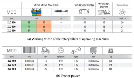
Figure 1.
Data from zanon.it.
As for the locomotion, it was decided that a pair of steering axle shafts without a braking system would be installed for the front transmission, with a square section of 40 mm and a four-hole Balilla junction [26], and that the rover would be rear-wheel drive. By placing the entire propulsion system on the rear axle, as is often the case in traditional tractors, the batteries could then be used to balance the vehicle by positioning them on the front chassis. For the rear actuators, Benevelli TX2 series motors were used (see Figure 2).
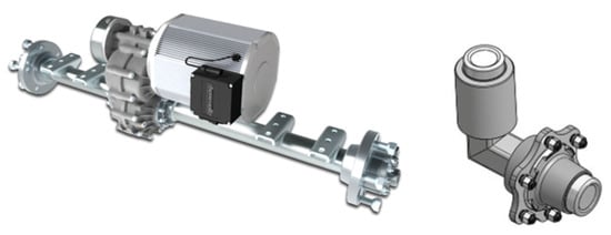
Figure 2.
Rear axle and front axle shaft.
In this phase, the sizing relative to the estimation of the position of the vehicle’s centre of gravity concerns the known masses and their position with respect to a reference system [27]. The position of the centre of gravity will help to calculate the weight distribution on the front and rear axles. As for the isodiametric vehicle, the weight must be distributed evenly, with 50% on the front axle and 50% on the rear axle [28]. In our calculations, the allocation of the centre of gravity resulted in the vehicle’s longitudinal axis of symmetry being 89.2 mm higher than the vertical axis and 725.4 mm further away from the longitudinal axis. Once the position of the centre of gravity was determined, the focus shifted to the weight dispersion on the axes [29]. By placing the battery pack on the front axle without any tool connected to the vehicle, the front axle would then bear 89.6 % of the weight. However, it should be borne in mind that the three-point hitch and the second engine for the power take-off (PTO) in the rear part of the vehicle still need to be evaluated [30].
Another aspect to consider is the choice of rims and tires to use for the vehicle. The European Tire and Rim Organization, a Belgian-based entity established in order to address the needs of tire manufacturers, provides specifications and harmonises sizes and nominal dimensions to avoid any ambiguity (see Table 1). However, to evaluate all the forces that are discharged on the tires, it is impossible to neglect the dynamic effects of the lifter’s handling of the operating machines [31]. For this reason, in the following section, all the activities carried out to evaluate the actions on the frame caused by the presence of the operating machine are reported.

Table 1.
Tyre measure and matching rim.
3. Numerical Activity
For the sizing of the chassis, it is necessary not to neglect the effect of the dynamic actions of the operating machine manoeuvred during the various processes [17]. For this reason, the SimScape environment of Mathworks was used to model a generic operating machine and the lifting mechanism. These geometries, shown in Figure 3, were modelled in Solidworks and imported into the multibody modelling environment.
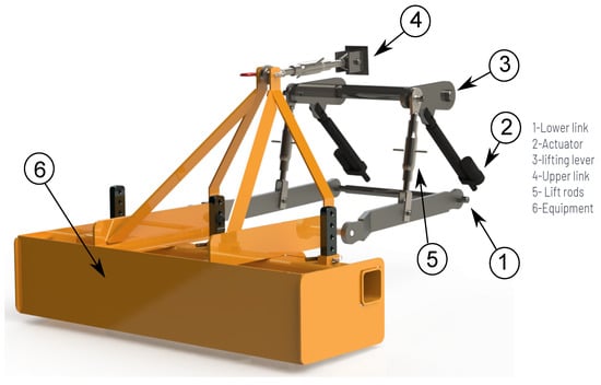
Figure 3.
A 3D Model of the equipment attached to the three-point hitch, designed in the Solidworks environment.
An MBD (model base design) approach was adopted for the development of the multibody model. In this way, starting from a simplified model of the system and the drives, it was possible to build a particularly efficient and effective model in stages in order to determine the requirements that the drive system must possess. For the numerical activity reported, an electromechanical model of the drive was developed, the parameters of which are given in Table 2. The kinematic model of the lead screw mechanism and a friction model were also added to the model, to evaluate the irreversible behaviour. The lifting system had been designed by taking into account the ISO730 directives and category 1, which include vehicles with a PTO power of up to 48 kW.

Table 2.
Electric motor data.
Furthermore, this choice was justified by the desire not to use a hydraulic system on the vehicle, a system that is generally used on traditional machines to operate the hydraulic pistons for lifting operating machines.
Furthermore, the choice of using a worm screw drive allowed for the exploitation of the irreversibility of the mechanism itself, in order to keep the lifting mechanism in position without having to supply torque and, in this way, to save energy [32].
The mechanism’s representation and its equivalent mechanical model are reported in Figure 4. The load is pushed up or down, depending on the direction of the screw’s rotation. Due to the presence of the load, frictional stresses are expected to arise between the thread and the slider, which the actuator will have to overcome [33,34]. The screw is essentially characterized by the pitch and the nominal radius that define the slope of the thread according to the following relation:
From the equilibrium at the translation of the system schematized in Figure 4, it is possible to write the final expression as follows:
where W is the load, P is the peripheral active force , and is the friction cone .
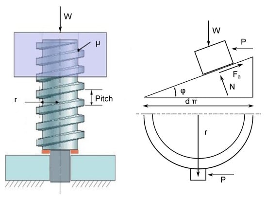
Figure 4.
Representation of self-locking screw and equivalent mechanical model during down motion.
With (2), it is possible to identify the condition in which the mechanism becomes irreversible. In the case of , the active force P must be applied to move the load.
In order to analyse the behaviour of a more detailed model, a multibody model was developed by importing a three-dimensional CAD into the SimScape multidomain simulation environment [18,35].
The study of multibody systems consists of the analysis of the dynamic behaviour of rigid or flexible bodies interconnected by constraints, each of which can undergo large translational and rotational displacements, depending on the force fields to which they are subjected.
Figure 5 shows the 3D rendering of the electromechanical drive and its sub-model in the SimScape environment.
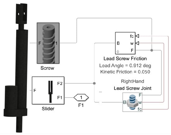
Figure 5.
Multibody model of the lead screw mechanism.
The performance of this mechanism can be assessed by the following relations:
As shown in Figure 5, the helix angle is equal to deg, while the friction cone angle is equal to deg. For these values, the mechanical efficiency in the retrograde mechanism is equal to . Inside the lead screw friction block, visible in Figure 5, a continuous stick-slip friction model is implemented, which is used to determine the friction force and torque coefficients according to the rotation speed of the screw–nut system connected to the joint [36,37]. An irreversible drive will allow the electric motors to be used only while manoeuvring the operating machine [38].
Smaller values for the velocity threshold and the low-pass filter constant make the model more realistic but result in a numerically stiffer system. The hypothesized agricultural machine must be able to work mainly autonomously and, only in particular cases, be managed remotely [39].
Several numerical simulations were carried out to evaluate the dynamic behaviour of the electromechanical system and the effects attributable to the inertial actions on the frame [40,41].
In this paper, three different case studies are presented to evaluate the correlation between the robustness of the control system, the mechanism’s coefficient of friction, and the related constraint reactions that are transferred to the frame.
The first scenario led back to an autonomous mission. The operating machine from the rest position initially had to be brought into contact with the ground to be worked, and only then could it be sunk by the amount indicated in Figure 1a.
In the second case, the activation of the stress control system was emulated during a machining operation due to an excessive resistance to advancement by the operating machine. In such cases, the lifter management system needs to raise the machine in order to free the vehicle.
Finally, the third case study aimed to test the realization of the non-back-drivable condition, which depends on the friction coefficient value in the case of a sudden change in the vehicle altitude (for example, a difference in the height of the ground). Figure 6a,b show the reference positions and the real positions occupied by the operating machine with two different PID controllers, for two of the scenarios mentioned above [42]. However, Figure 6c reports the difference in height of the ground used for testing the non-back-drivable behaviour of the mechanism. The goal for the first two simulations was to analyse the dynamic effects that would be transmitted onto the frame for two particular operating conditions, considering both the effects due to the robustness of the control system and the friction coefficient of the mechanism. The last analysis, however, had the goal of testing the effectiveness of the irreversible mechanism in the presence of variable inertial loads [43,44]. Having chosen the size of the electric motor by means of a preliminary inverse dynamic analysis, the aim of the authors was to investigate the correlation between the robustness of the PID controller and the constraint reactions that would be discharged on the frame. A control system with lower performance was indicated for the controllers with PID I, while a much more robust PID controller was considered for those with PID II.
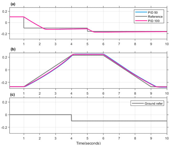
Figure 6.
Reference and actual motion of the multibody model of the operating machine for: (a) sinking of the operating machine; (b) handling for effort control; (c) Abrupt change in the terrain profile.
4. Results
As can be seen in the first two graphs of Figure 6, the two different controllers qualitatively return the same positioning for the operating machine, both during the lowering and the beginning of the tillage (case a) and as regards the activation of the effort management system to overcome a possible obstacle present in the ground (case b).
On the other hand, this argument cannot be made when commenting on Figure 7. This image shows the constraint reactions on the longitudinal plane for the first four points indicated in Figure 3. In particular, it is possible to appreciate how the use of a more robust PID controller results in a doubling of the reaction values. This behaviour is also recorded in a decidedly significant way in the second case study; the results are shown in Figure 8. In both cases, the particularly stressed joints are the drive attachment point (see point 2 of Figure 3) and the lifting lever (see point 3 of Figure 3). Such results suggest a possible future improvement of the kinematic chain used for the lifter.
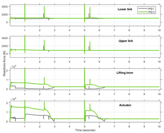
Figure 7.
Correlation of reaction forces calculated with various PID.
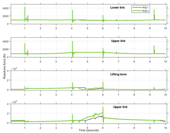
Figure 8.
Correlation of the reaction forces determined with increasing dynamic friction coefficients.
Figure 9 shows the correlation between friction and the behaviour of the mechanism in the event of a sudden change in vehicle altitude. In particular, this analysis aimed to capture the reversibility and irreversibility conditions for the chosen mechanism, depending on the friction value. In Figure 9a, a red line indicates the irreversible behaviour of the lift chosen for the electric vehicle. For a friction value of 0.017, a self-braking condition by the mechanism was identified, while for a value of 0.024, a self-locking condition was found. Furthermore, in Figure 9b, for a value of 0.015, it is possible to see the reversible behaviour of the mechanism with the lowering of the load, even before the irregularity (t > 4 s). The subsequent behaviour by the load is due to the geometric limit switches of the drive.
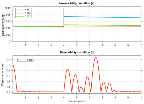
Figure 9.
Correlation of the reaction forces determined with increasing dynamic friction coefficients: (a) Irreversibility condition; (b) Reversibility condition.
The self-locking condition is obtained when the angle of the friction cone is greater than the helix angle. The following self-locking factor r can be defined in the following way:
If the self-locking factor is greater than unity, there will be no movement in static conditions. In our case, by applying (4) and considering the helix angle of the mechanism, it was possible to estimate the friction coefficient necessary for self-locking with a factor of 1.1.
On the other hand, the automatic braking condition is verified when the friction energy that is transmitted from the nut is greater than the energy adduce from the screw. In this case, the braking factor, indicated with b, is evaluated in the following way:
In this case study, b must be equal to for a low feed rate [45].
It is important to always keep in mind that the self-locking action (static condition) does not necessarily include the self-braking action (dynamic condition). In Figure 9, the cases of irreversible condition and reversible condition are illustrated.
To summarize what has been highlighted, the areas of reversibility and irreversibility as a function of the thread angle and the friction coefficient of the mechanism were graphically represented. Figure 10 illustrates the so-defined stability map of the mechanism, which shows both the helix angle values and the friction value used (metal contact on lubricated metal) for this application as well as the conditions shown in the previous graph. On the stability map, it is possible to see how the mechanical performance changes as a function of the two parameters mentioned above. Furthermore, this map is useful in the eventual redesign of the actuation device, which will modify the dynamic behaviour of the lifter [46].
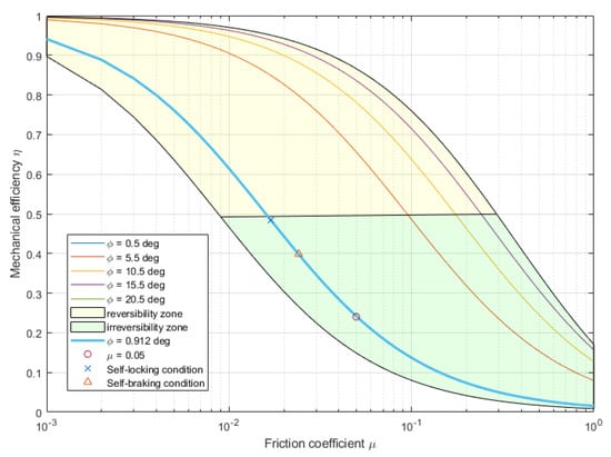
Figure 10.
Correlation of the reaction forces determined with increasing dynamic friction coefficients.
The preliminary concept of the electric tractor is shown in Figure 11. However, the results exhibited in this work and a subsequent phase of geometry optimization will significantly influence the final shape of the vehicle.
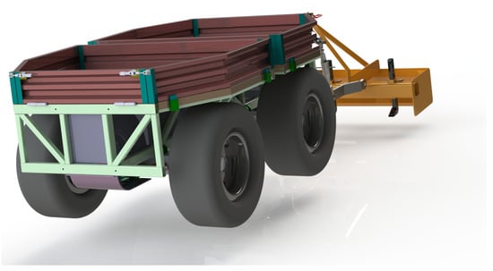
Figure 11.
A 3D rendering of the concept.
5. Conclusions
This paper reports the preliminary phase of a much larger project, which is focused on the development of a new autonomous electric tractor for greenhouse and open-field applications.
The use of virtual modelling and prototyping techniques together with the low cost of electronic components makes it possible to significantly lower both the cost and the development time of a new machine. It also completely breaks down the technology gaps that have precluded less industrialized countries from competing with industrialized countries on equal footing.
After identifying the basic components for the construction of the vehicle, such as the chassis, tires, transmission, engine, battery, and lift, the authors focused on the reference standard for the sizing and design of the vehicle in order to estimate the centre of gravity of the whole system. The rover’s centre of gravity remained the most sensitive variable needed to proceed with the dynamic analyses. To estimate the centre of gravity, it was necessary to evaluate the constraint reactions transmitted onto the frame by the lifter and the power take-off because the centre of gravity was positioned too far forward, and therefore the weight distribution between the two axes was unbalanced (front and rear). For this reason, the study focused on the rear part of the tractor, and in particular, on the lifting mechanism, which had been designed and sized. To evaluate the reactions transmitted to the frame by the lifter, the system was modelled and simulated in Mathworks’ SimScape multidomain simulation environment. Inverse dynamic analyses made it possible to identify the characteristics required of the electric motors. The direct dynamic analysis, on the other hand, made it possible to test the reversible and irreversible behaviour of the lifter for an optimal component design. The results were essential for the subsequent chassis design phase and for the final vehicle construction phase. The irreversible electromechanical drive proposed by the authors was designed for a newly developed all-electric or hybrid tractor. However, nothing detracts from the fact that such a solution could also be thought of for the retrofitting of machines that are already on the market. Such a scenario, although unlikely given that hydraulic circuits are also used to operate the steering and power external users in conventional tractors, would require a retrofit of the machine itself. In such a case, it would be necessary to equip the vehicle with the appropriate energy accumulators to ensure lifter manoeuvrability. It would also be necessary to install a microcontroller that is capable of handling the drive. Such a solution could be part of a retrofitting process for obsolete machines, which would extend the useful life of machines destined for decommissioning. On the other hand, using an irreversible mechanism on tractors that use hydraulic systems would make the machine fail-safe for the circuit itself.
Author Contributions
Conceptualization, M.C.D.S. and S.V.; validation, M.C.D.S. and D.G. All authors have read and agreed to the published version of the manuscript.
Funding
This research received no external funding.
Institutional Review Board Statement
Not applicable.
Informed Consent Statement
Not applicable.
Conflicts of Interest
The authors declare no conflict of interest.
References
- Mehla, A.; Deora, S. Use of Machine Learning and IoT in Agriculture. In EAI/Springer Innovations in Communication and Computing; Springer: Berlin/Heidelberg, Germany, 2022; pp. 277–293. [Google Scholar] [CrossRef]
- De Simone, M.; Celenta, G.; Rivera, Z.; Guida, D. Mechanism Design for a Low-Cost Automatic Breathing Applications for Developing Countries. Lect. Notes Netw. Syst. 2022, 472, 345–352. [Google Scholar] [CrossRef]
- Vitlox, O. Technological Developments in Agricultural Machinery. Eur. J. Mech. Environ. Eng. 1983, 30, 19–25. [Google Scholar]
- Proceedings of the 11th International Symposium on Farm Machinery and Processes Management in Sustainable Agriculture, FMPMSA 2022, Bari, Italy, 13–15 June 2022; Volume 289. Lecture Notes in Civil Engineering.
- De Simone, M.; Rivera, Z.; Guida, D. Obstacle avoidance system for unmanned ground vehicles by using ultrasonic sensors. Machines 2018, 6, 18. [Google Scholar] [CrossRef]
- Olalla, E.; Cadena-Lema, H.; Domínguez Limaico, H.; Nogales-Romero, J.; Zambrano, M.; Vásquez Ayala, C. Irrigation Control System Using Machine Learning Techniques Applied to Precision Agriculture (Internet of Farm Things IoFT). Lect. Notes Netw. Syst. 2022, 512, 329–342. [Google Scholar] [CrossRef]
- Celenta, G.; De Simone, M. Retrofitting Techniques for Agricultural Machines. Lect. Notes Netw. Syst. 2020, 128, 388–396. [Google Scholar] [CrossRef]
- Casillo, M.; Colace, F.; Lorusso, A.; Marongiu, F.; Santaniello, D. An IoT-Based System for Expert User Supporting to Monitor, Manage and Protect Cultural Heritage Buildings. Stud. Comput. Intell. 2022, 1030, 143–154. [Google Scholar] [CrossRef]
- Di Filippo, A.; Lombardi, M.; Marongiu, F.; Lorusso, A.; Santaniello, D. Generative design for project optimization. In DMSVIVA; KSI Research: Pittsburgh, PA, USA, 2021; pp. 110–115. [Google Scholar]
- Casillo, M.; Gupta, B.; Lombardi, M.; Lorusso, A.; Santaniello, D.; Valentino, C. Context Aware Recommender Systems: A Novel Approach Based on Matrix Factorization and Contextual Bias. Electronics 2022, 11, 1003. [Google Scholar] [CrossRef]
- La Regina, R.; Pappalardo, C.; Guida, D. Dynamic Analysis and Attitude Control of a Minisatellite. Lect. Notes Netw. Syst. 2022, 472, 244–251. [Google Scholar] [CrossRef]
- Sato, S.; Jiang, Y.; Russell, R.; Miller, J.; Karavalakis, G.; Durbin, T.; Johnson, K. Experimental driving performance evaluation of battery-powered medium and heavy duty all-electric vehicles. Int. J. Electr. Power Energy Syst. 2022, 141, 108100. [Google Scholar] [CrossRef]
- Ghobadpour, A.; Monsalve, G.; Cardenas, A.; Mousazadeh, H. Off-Road Electric Vehicles and Autonomous Robots in Agricultural Sector: Trends, Challenges, and Opportunities. Vehicles 2022, 4, 843–864. [Google Scholar] [CrossRef]
- Manrique-Escobar, C.; Pappalardo, C.; Guida, D. A multibody system approach for the systematic development of a closed-chain kinematic model for two-wheeled vehicles. Machines 2021, 9, 245. [Google Scholar] [CrossRef]
- De Simone, M.; Laiola, V.; Rivera, Z.; Guida, D. Dynamic Analysis of a Hybrid Heavy-Vehicle. Lect. Notes Netw. Syst. 2022, 472, 236–243. [Google Scholar] [CrossRef]
- Pappalardo, C.; Vece, A.; Galdi, D.; Guida, D. Developing a Reciprocating Mechanism for the Emergency Implementation of a Mechanical Pulmonary Ventilator using an Integrated CAD-MBD Procedure. FME Trans. 2022, 50, 238–247. [Google Scholar] [CrossRef]
- De Simone, M.; Ventura, G.; Lorusso, A.; Guida, D. Attitude Controller Design for Micro-satellites. Lect. Notes Netw. Syst. 2021, 233, 21–31. [Google Scholar] [CrossRef]
- Curcio, M.; Pappalardo, C.; Guida, D. Multibody Modeling and Dynamical Analysis of a Fixed-Wing Aircraft. Lect. Notes Netw. Syst. 2022, 472, 77–84. [Google Scholar] [CrossRef]
- Sicilia, M.; De Simone, M. Development of an Energy Recovery Device Based on the Dynamics of a Semi-trailer. In Lecture Notes in Mechanical Engineering; Springer: Cham, Switzerland, 2020; pp. 74–84. [Google Scholar] [CrossRef]
- Pappalardo, C.; Lettieri, A.; Guida, D. Identification of a Dynamical Model of the Latching Mechanism of an Aircraft Hatch Door using the Numerical Algorithms for Subspace State-Space System Identification. IAENG Int. J. Appl. Math. 2021, 51, 1–14. [Google Scholar]
- Shanmugasundar, G.; Sivaramakrishnan, R.; Venugopal, S. Modeling, design and static analysis of seven degree of freedom articulated inspection robot. Adv. Mater. Res. 2013, 655–657, 1053–1056. [Google Scholar] [CrossRef]
- Menon, A.; Prabhakar, M. Intelligent IoT-Based Monitoring Rover for Smart Agriculture Farming in Rural Areas. Lect. Notes Netw. Syst. 2022, 401, 619–630. [Google Scholar] [CrossRef]
- Botta, A.; Moreno, E.; Baglieri, L.; Colucci, G.; Tagliavini, L.; Quaglia, G. Autonomous Driving System for Reversing an Articulated Rover for Precision Agriculture. Mech. Mach. Sci. 2022, 120, 412–419. [Google Scholar] [CrossRef]
- Henry, D.; Aubert, H.; Galaup, P.; Veronese, T. Dynamic Estimation of the Yield in Precision Viticulture from Mobile Millimeter-Wave Radar Systems. IEEE Trans. Geosci. Remote Sens. 2022, 60, 4704915. [Google Scholar] [CrossRef]
- Ribeiro, J.; Gaspar, P.; Soares, V.; Caldeira, J. Computational Simulation of an Agricultural Robotic Rover for Weed Control and Fallen Fruit Collection-Algorithms for Image Detection and Recognition and Systems Control, Regulation, and Command. Electronics 2022, 11, 790. [Google Scholar] [CrossRef]
- Kuska, M.; Heim, R.; Geedicke, I.; Gold, K.; Brugger, A.; Paulus, S. Digital plant pathology: A foundation and guide to modern agriculture. J. Plant Dis. Prot. 2022, 129, 457–468. [Google Scholar] [CrossRef] [PubMed]
- Netthonglang, C.; Jongrukchob, T.; Thongtan, T.; Bairaksa, J. Real-time and online post-processing kinematic positioning services. In Proceedings of the 2022 19th International Conference on Electrical Engineering/Electronics, Computer, Telecommunications and Information Technology, Prachuap Khiri Khan, Thailand, 24–27 May 2022. [Google Scholar] [CrossRef]
- Dobretsov, R.; Dobretsova, S.; Voinash, S.; Shcherbakov, A.; Dolmatov, S.; Sokolova, V.; Taraban, V.; Alekseeva, S.; Taraban, M. Elements of the mathematical support for the design of an autonomous tractor. IOP Conf. Ser. Earth Environ. Sci. 2021, 723, 032039. [Google Scholar] [CrossRef]
- Nunez-Quispe, J.; Lleren-Sernaque, J.; Lara-Chavez, E. Mechanical Design of a ROVER prototype for Exploration tasks on Mars: Structural and Transient Dynamics simulation analysis. In Proceedings of the 2021 IEEE MIT Undergraduate Research Technology Conference (URTC), Cambridge, MA, USA, 8–10 October 2021. [Google Scholar] [CrossRef]
- Manrique-Escobar, C.; Pappalardo, C.; Guida, D. On the Analytical and Computational Methodologies for Modelling Two-wheeled Vehicles within the Multibody Dynamics Framework: A Systematic Literature Review. J. Appl. Comput. Mech. 2022, 8, 153–181. [Google Scholar] [CrossRef]
- Renius, K.T. Fundamentals of Tractor Design; Springer: Cham, Switzerland, 2020. [Google Scholar]
- Cho, M.S.; Hwang, H.S.; Lee, M.H.; Kim, B.; Zinn, M.R. A screwjack mechanism based separation device driven by a piezo actuator. Int. J. Precis. Eng. Manuf. 2012, 13, 2079–2082. [Google Scholar] [CrossRef]
- Gallina, P. Vibration in screw jack mechanisms: Experimental results. J. Sound Vib. 2005, 282, 1025–1041. [Google Scholar] [CrossRef]
- Liguori, A.; Armentani, E.; Bertocco, A.; Formato, A.; Pellegrino, A.; Villecco, F. Noise reduction in spur gear systems. Entropy 2020, 22, 1306. [Google Scholar] [CrossRef]
- Cammarata, A.; Maddío, P.D. A system-based reduction method for spatial deformable multibody systems using global flexible modes. J. Sound Vib. 2021, 504, 116118. [Google Scholar] [CrossRef]
- De Simone, M.; Guida, D. Modal coupling in presence of dry friction. Machines 2018, 6, 8. [Google Scholar] [CrossRef]
- Formato, A.; Ianniello, D.; Pellegrino, A.; Villecco, F. Vibration-based experimental identification of the elastic moduli using plate specimens of the olive tree. Machines 2019, 7, 46. [Google Scholar] [CrossRef]
- Noormohamed, A.; Mercan, O.; Ashasi-Sorkhabi, A. Optimal active control of structures using a screw jack device and open-loop linear quadratic gaussian controller. Front. Built Environ. 2019, 5, 43. [Google Scholar] [CrossRef]
- Formato, A.; Romano, R.; Villecco, F. A Novel Device for the Soil Sterilizing in Sustainable Agriculture. Lect. Notes Netw. Syst. 2021, 233, 858–865. [Google Scholar] [CrossRef]
- Shanmugasundar, G.; Sivaramakrishnan, R. Design and analysis of a newly developed seven degree of freedom robot for inspection. Int. J. Control Theory Appl. 2016, 9, 393–402. [Google Scholar]
- Cammarata, A.; Sinatra, R.; Maddìo, P.D. Static condensation method for the reduced dynamic modeling of mechanisms and structures. Arch. Appl. Mech. 2019, 89, 2033–2051. [Google Scholar] [CrossRef]
- Araki, Y.; Asai, T.; Kimura, K.; Maezawa, K.; Masui, T. Nonlinear vibration isolator with adjustable restoring force. J. Sound Vib. 2013, 332, 6063–6077. [Google Scholar] [CrossRef]
- Thesiya, D.; Srinivas, A.; Shukla, P. A novel axial foldable mechanism for a segmented primary mirror of space telescope. J. Astron. Space Sci. 2015, 32, 269–279. [Google Scholar] [CrossRef][Green Version]
- Li, T.; Kou, Z.; Wu, J.; Yahya, W.; Villecco, F. Multipoint Optimal Minimum Entropy Deconvolution Adjusted for Automatic Fault Diagnosis of Hoist Bearing. Shock Vib. 2021, 2021, 6614633. [Google Scholar] [CrossRef]
- Manuale Degli Organi Delle Macchine; Tecnologie Industriali: Padova, Italy, 2006.
- Sun, X.; Liu, H.; Song, W.; Villecco, F. Modeling of eddy current welding of rail: Three-dimensional simulation. Entropy 2020, 22, 947. [Google Scholar] [CrossRef]
Publisher’s Note: MDPI stays neutral with regard to jurisdictional claims in published maps and institutional affiliations. |
© 2022 by the authors. Licensee MDPI, Basel, Switzerland. This article is an open access article distributed under the terms and conditions of the Creative Commons Attribution (CC BY) license (https://creativecommons.org/licenses/by/4.0/).