Abstract
Quantification and minimisation of energy consumption in resonant MEMS micromirrors is a key aspect for a proper structural design. In this setting, the quality factor Q of the drive mode of the device needs to be estimated and, eventually, improved. In this work, we propose a simulation strategy for the numerical computation of MEMS micromirrors quality factors. Full order Arbitrary Lagrangian Eulerian Navier-Stokes simulations have been performed using a SUPG stabilised Chorin-Themam scheme. Finally, the numerical results are compared with experimental data, highlighting the accuracy and efficiency of the proposed method.
1. Introduction
Micro-Electro-Mechanical Systems (MEMS) provide an interface to connect the digital world to the real world [1]. Within this broad class of devices, MEMS micromirrors are essential for high-end applications as augmented reality headsets and LiDaR systems [2,3]. Indeed, their small size combined with a high aperture angle allows realising compact systems for optical signal manipulation [4]. In the context of MEMS micromirrors design, quantitative methods to perform a-priori estimation of system parameters are crucial since the high fabrication costs, along with an extensive production time, hinder trial-and-error approaches. Furthermore, since industrial-level MEMS devices typically feature complex geometries, numerical methods are of uttermost importance in the design flow of such components.
Among the different parameters that need to be estimated during the design phase of MEMS micromirrors, energy dissipation retains a special role. Indeed, the miniaturisation of the full device strongly depends on the energy requirements of the embedded mechanical components. For systems that operate at resonance like most MEMS micromirrors, the parameter that quantifies energy dissipation is the quality factor Q of the drive mode [5,6]. This parameter needs to be properly optimised in order to minimise energy consumption while avoiding robustness problems during drops and impacts [7,8]. In the context of MEMS devices this represents a major challenge since damping sources are numerous and include, e.g., gas damping [9], thermoelastic damping [10,11], anchor losses [12], materials hysteretic behaviour [13], and electrical losses [14]. For piezoelectrically actuated MEMS micromirrors, the two major energy losses are the hysteretic behaviour of the piezoelectric material used for actuation, and the energy dissipation caused by the fluid flow [15].
In the present investigation, we focus on the quantification of energy losses due to fluid-damping in MEMS micromirrors with emphasis on devices that operate in air at ambient pressure [16]. Developing a reliable model for air damping represents a crucial aspect. In this framework, several works can be found in the literature, e.g., for out-of-plane comb drive micromirrors [17,18], and 2D MEMS electromagnetically driven micromirrors [19]. Moreover, early numerical analyses of the air damping for micromirrors have already been presented in the literature applying a finite volume method [20], a PISO pressure-velocity coupling scheme [21] implemented in commercial software (ANSYS), or a one-way Fluid-Structure-Interaction (FSI) [22]. To provide a quantitative estimate of the energy losses, the quality factor Q of the associated dynamic system is computed numerically starting from its definition as the ratio between the maximum energy stored in the system and the energy dissipated during one cycle. This numerical prediction is compared with the value extracted from the experimental Frequency Response Curves (FRCs) using some approximate relations proposed by Davis [23]. However, Davis’ formulas are valid under specific assumptions, which may not always be satisfied, especially for MEMS that feature strong nonlinear modal interaction with coupled non-resonant modes [24]. Among the main assumptions exploited by Davis to derive analytical relations for the quality factor, we mention that the nonlinearity of the dynamical system must be cubic. Even if this is a very typical situation [24], real devices might undergo a more complex pattern [25,26]. Moreover, the damping forces must be at most quadratic and this implies that the fluid motion around the structure must be non-chaotic, i.e., the fluid motion must preserve a periodic nature.
To better predict parameters associated with dissipation in MEMS micromirrors subjected to large amplitude vibrations, we here develop and validate an Arbitrary Lagrangian Eulerian (ALE) finite element solver for the Navier-Stokes equations [27]. The peculiarities of the solver we propose are the use of a Chorin-Temam scheme to speed up the computational times associated with the solver, together with the adoption of a Streamline-Upwind-Petrov-Galerkin (SUPG) finite element scheme for the space discretisation, the latter being necessary to avoid numerical instability as a result of linear momentum convection. Furthermore, the motion law of the grid is obtained by leveraging the displacement law proposed in [28], which provides remarkable robustness against flipping elements and element skewness. The choice of an ALE approach is justified by the necessity to model the large amplitude vibrations achieved by the device during actuation and resonance combined with the high accuracy of the adopted numerical scheme for both velocity and pressure fields. The harmonic movement of the device is first computed as the nonlinear normal mode of the mirror using the recently developed theory of invariant manifolds [29,30,31,32]. The velocity field on the surface of the solid is then applied as a boundary condition to the mirror surface during the ALE analysis and the quality factor is computed. As a consequence, we are not addressing a true FSI problem. We assume that the fluid forces will not meaningfully modify the deformed shape of the mirror, which seems a very reasonable assumption given the very limited value of the dissipation and the large structural stiffness of MEMS micromirrors [33].
Two types of micromirrors are analysed. The former device rotates around a fixed axis given by the torsional springs directly attached to the substrate. The rotation is induced by four trapezoidal beams actuated with piezo patches and connected to the reflective surface by means of flexible folded springs. In the latter device, the central mirror is on the contrary suspended to a gimbal-like structure on which piezo patches are directly deposited. It is worth noticing that the devices are not represented as rotating rigid bodies, which is a limitation if micromirrors with large deformable parts need to be addressed [34].
The organisation of the paper is as follows. After a brief description of the micromirrors and of the experimental setup exploited for quality factor measurement in Section 2, the fluid model describing the surrounding air, as well as the numerical approach, are detailed in Section 3. Finally, in Section 4 we address the validation of the proposed model by comparing the numerical and experimental results for the two micromirrors taken into consideration.
2. Devices and Experimental Data
The tested micromirrors illustrated in Figure 1 have been fabricated by STMicroelectronics™ using monocrystalline silicon with the [110] orientation aligned with the axis. The sol-gel piezoelectric (PZT) patches, the passivation layers and the electrodes have been deposited with the Petra Thin-Film Piezoelectric technology developed by STMicroelectronics™. The resonance frequency of the torsional mode of the structures are 1950 Hz and 25,500 Hz, respectively, and more details about layout, materials and fabrication can be found, e.g., in [35,36].
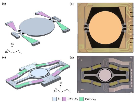
Figure 1.
Geometries of Micromirror 1 (a) and Micromirror 2 (c); optical microscope pictures of the tested devices for Micromirror 1 (b) and Micromirror 2 (d). Grey colour is used for silicon. Pink and light green colours are used to highlight the PZT actuation patches and denote different actuation biases. The reflective surfaces have radii of 1500 m and 900 m, respectively.
The structure of the first micromirror, henceforth Micromirror 1, is illustrated in Figure 1a: a differential bias is applied on piezoelectric material patches (PZT-V and PZT-V), which leads to mechanical deformation due to the converse piezoelectric effect. This deformation causes a bending of the folded springs that link the main body of the device with the piezoelectric components. As a consequence of this deformation process, the reflective surface, with a radius of 1500 m, is forced to oscillate around the rotation axis, identified by the suspension springs on the lateral sides of the device. The structure of the second micromirror, labelled Micromirror 2, is depicted in Figure 1c, where the central mirror, with a radius of 900 m, is suspended to a gimbal-like structure and the piezoelectric material patches, highlighted on both sides of the device, cause its bending around the rotational axis. Moreover, both structures are anchored to the substrate with rigid connections, as can be seen in Figure 1b,d.
The monitoring of the opening angle of the piezoelectric micromirror was obtained with the setup illustrated in Figure 2, which measures the deflection of a laser beam incident on the device. The resonant movement of the micromirror projects a laser segment on a target which is acquired by a camera and then processed. The control software gives the possibility to set the scanning frequency range, step and direction of the sweep (up or down).
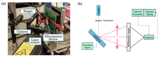
Figure 2.
Experimental setup (a) and schematic representation of the measurement technique adopted (b) for collecting and postprocessing experimental data [37].
The experimental campaign has been performed by direct analysis in time. A forward sweep over the frequencies of interest is performed and, for each frequency, the steady state is reached. After recording the amplitude a new frequency is addressed. This is a very robust technique that, however, permits to simulate only the stable branches of the response. In Figure 3 we report amplitude vs. frequency plots for five different actuation potentials in the case of Micromirror 1 and three different actuation potentials in the case of Micromirror 2. Sudden jumps in the plots correspond to abrupt transitions between stable branches of the curves and occur whenever the onset of an unstable branch is met at bifurcation points.
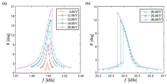
Figure 3.
Experimental FRCs for Micromirror 1 (a) and Micromirror 2 (b). Each marker represents a different experiment where the frequency of the device is fixed and the maximum opening angle is measured.
These plots will be used in Section 4 to obtain an estimate of the quality factor Q based on simplified formulas. From the experimental FRCs, we obtain the maximum amplitude of the micromirrors reflecting surfaces at the resonance frequency of the torsional mode for each actuation voltage amplitude. These data are presented in Table 1a and Table 1b, respectively for Micromirror 1 and Micromirror 2.

Table 1.
Maximum opening angles at the resonance frequency of the torsional mode for different actuation voltage amplitude. They are computed from experimental FRCs in Figure 3 for Micromirror 1 (a) and Micromirror 2 (b).
Moreover, the measurement error for the amplitude angle is estimated to be around °. It is worth noticing that the higher the recorded angle, the more accurate the evaluation of the quality factor since the error propagation has less impact as the maximum amplitude increases.
3. Model for the Fluid Dynamics Surrounding Micromirror
In this section, we present the ALE mathematical formulation adopted to model the fluid dynamics. Starting from the governing physical equations, we address their discretisation and we introduce the numerical scheme, including stabilisation, applied to perform our simulations. ALE [27] is a finite element formulation in which the computational mesh is neither fixed in space (like, e.g., in Eulerian schemes) nor attached to material particles (like, e.g., in Lagrangian approaches). On the contrary, the computational mesh inside the domains can move arbitrarily with a velocity which is a-priori different from the fluid velocity and is chosen so as to optimize the shapes of elements.
In this framework, let us consider a final time and a generic bounded, Lipschitz and time-dependent domain . The fluid problem around the micromirror structure can be modelled with the following Navier-Stokes equations, for :
where is the spatial coordinate, t is the time variable, is the velocity field, is the domain velocity field, , where is the pressure field and is the fluid density, is a generic volume force per unit mass, is the kinetic viscosity and is the dynamic viscosity. Additionally, we assume fluid properties uniform with no spatial dependence. Equations (1) and (2) are endowed with the following mixed boundary conditions, for every :
where is the unit normal vector with respect to boundary , and are Dirichlet boundary and Neumann boundary portions such that:
and are known data. It is worth stressing that no-slip boundary conditions are applied as the Knudsen number remains everywhere well below since gaps between moving parts are relatively large [38]. Moreover, since a time derivative is involved, for the well-posedness of the model we have to add an initial condition, namely:
where is the initial configuration of the domain and is a given function.
To describe the motion of fluids around moving structures we have chosen an ALE approach where the grid follows a motion rule that is neither fixed nor that of the solid. We define as the motion of the frame:
where are the coordinates in the reference configuration. Moreover, we assume that is invertible and we define its inverse as . Thanks to this theoretical setting, we can properly define , as well as all the boundary portions, namely , for every time .
3.1. Numerical Solution
In order to numerically solve Equations (1) and (2), we need to operate both a spatial and time discretisation. For our purpose, we can assume from now on . Regarding the space discretisation, we choose to rely on a finite element method [39], namely the numerical fluid velocity field is quadratic and the numerical pressure field is linear on the mesh triangulation for every time.
The choice of these spaces is not arbitrary but they need to satisfy the so called Ladyzhenskaya–Babuška–Brezzi (LBB) condition [40]. We decided to discretise the solution spaces with because we can obtain a pressure field smoother than other LBB stable couples, e.g., elements [41], mini-element method [42] or Crouzeix-Raviart elements [43].
On the other hand, temporal discretisation is performed using a fractional step scheme based on the Chorin-Temam work [44,45]. Given the following time subdivision:
the strong formulation of Chorin-Temam incremental fractional step method [46,47] can be split into four different steps, for every . Step 1 consists in solving an ALE advection diffusion problem for intermediate fluid velocity , endowed with the same Dirichlet boundary condition in Equation (3) and with homogeneous Neumann boundary condition, as follows:
where , , Equation (9) is valid for every and, respectively, Equations (10) and (11) are applied to Dirichlet and Neumann boundary portions. Step 2 requires that a Poisson problem for pressure variation is solved, where the solution of the previous step appears on the right-hand side. Equations are displayed below:
Step 3, called the projection step, imposes the incompressibility condition to the fluid velocity field , namely it projects the intermediate fluid velocity field on the divergence-free subspace as follows:
Finally, in Step 4, we recover the pressure field from the variation of the pressure field computed in Step 2, namely:
The projection methods introduce a splitting error which is usually reflected in the appearance of artificial boundary layers on the pressure field in the closeness of the Neumann boundary portion of order , where:
In this context, the linear operator associated with the continuum differential problem in Equations (9)–(11) reads as:
and the weak stabilised SUPG problem requires finding such that:
where is the mesh discretisation, is the number of elements of , are stabilisation parameters, is the skew symmetric part of operator in Equation (18), obtained following [39], namely:
and (V,) are suitable test and solution Sobolev spaces. The skew symmetric operator for the proposed scheme is different with respect to the one associated with the standard incompressible Navier-Stokes equations since it lacks the divergence fluid velocity term. In our numerical algorithm, this additional term is crucial because the incompressibility constraint is imposed in Step 3. The choice of stabilisation parameter is not unique and it is usually element-dependent. From [48], the optimal value for is, for every :
where is the order of time discretisation, is the maximum of infinite norm among nodal fluid velocity solution, is the characteristic dimension of q-th element at k-th time step, and is a constant that depends on space discretisation. More precisely:
with m such that the pressure finite element space is . In our case, the pressure is linear, hence and . Moreover, for the Chorin-Temam method, we use a first order time discretisation, hence .
In conclusion, for the Chorin-Temam advection diffusion problem with elements, the optimal stabilisation parameter reads, for every k, as:
3.2. Mesh Displacement
In this subsection, we briefly discuss the law that governs the mesh displacement and the associated equations. It consists in the solution of a linear elliptic (Poisson-like) problem with anisotropic behaviour of the discretised mesh velocity field. In particular, anisotropy is prescribed as a function of the domain triangulation, hence avoiding excessive element distortion. Anisotropy is introduced at the element level using a spring-like analogy.
It is inspired by Bottasso’s work [28] which introduces fictitious springs connecting nodes and faces, see Figure 4. For every node i of the mesh triangulation, two sets of equations are imposed stating that forces from edge-node springs must balance as well as forces from vertex-ball springs.
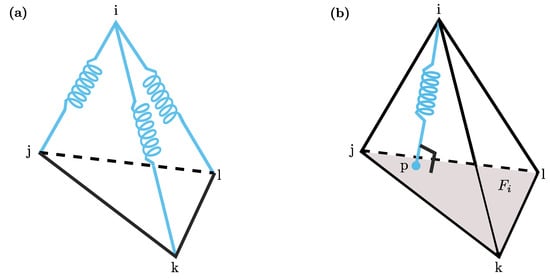
Figure 4.
Visual representation of fictitious springs used to compute the mesh velocity. In particular, the edge-node springs and vertex-ball spring associated with i-th node are depicted in (a) and (b), respectively.
The first one states that:
where N is the total number of nodes and is the force that node i exerts on the adjacent node j, which is proportional to the inverse of the distance between the two nodes (see Figure 4a). Regarding the second set of equations, for every node the following relation is imposed:
where is the force that node i exerts on the virtual node p that is the projection of i on the opposite face , denotes the number of faces in the range of the polyhedral = ball(i) that encloses the i-th node, and is the set of faces that encircle the node i and are one edge away from it (see Figure 4b).
3.3. Quality Factor
In this subsection, we introduce the notion of quality factor Q and discuss the procedure for computing Q during the ALE simulations.
The quality factor Q of an oscillatory dynamic system is a dimensionless parameter that describes the significance of damping. In a more general way, it can be defined as:
where E is the maximum energy stored in the device and is the energy dissipated in each oscillation cycle. To obtain an estimate of these quantities, we first compute the time evolution of the kinetic energy K of the micromirror and the dissipated power over the micromirror surfaces, respectively, as follows:
where is the density of the structure and represents the mirror surfaces. It is worth noticing that in the computation of power we take into account only the pressure forces and we neglect the viscous ones: this is a suitable approximation since in these applications the dissipation phenomena due to friction are almost negligible.
According to the definition proposed in [20], the Reynolds number ranges from 5000 to 25,000 for Micromirror 1 and from 72,000 to 103,000 for Micromirror 2.
In particular, we set E as the maximum kinetic energy over a period , while is obtained through a time integration of the dissipated power, namely:
4. Numerical Results
Numerical simulations on Micromirror 1 and Micromirror 2 are carried out using a workstation with AMD Ryzen 5950X processor and 128 Gb RAM. In both geometries, the computational domain is a box that contains the mirror. The micromirror is oriented such that the reflective surface is parallel to the plane and it is positioned at a height from the bottom of the cavity that allows reproducing the depth of the real micromirror’s cavity. The fluid under consideration is air with MPa s and ng/m, while the solid material of the micromirror is single crystal silicon, with a density ng/m. The computational time is set as four times the oscillation period, namely , to let the solution reach a stationary regime. In order to perform our simulations, we need to assign proper boundary conditions to the fluid velocity and pressure field. The external box is divided into two regions: as far as the fluid velocity is concerned, in the upper part homogeneous Neumann boundary conditions are imposed, while in the lower part Dirichlet homogeneous boundary conditions are applied. The separation line between portions is positioned just above the micromirror in its rest configuration and represents the upper edges of the rigid walls of the package in which the mirror is placed. Moreover, we recall that, in the case of the Chorin-Temam method, homogeneous Neumann boundary conditions for the fluid velocity field imply homogeneous Dirichlet boundary conditions for the pressure field. Furthermore, the boundary conditions on the surfaces of the device are of no-slip type. Moving on to the boundary conditions associated with the mesh velocity problem, we set no-slip boundary conditions on the micromirror surfaces, while, on the box, carriage boundary conditions are applied, namely, zero mesh velocity on the edges and zero normal mesh velocity on the faces.
The numerical solver is implemented in Julia [49] and the associated pseudo code is reported in Algorithm 1, where the main steps are underlined. In particular, T is the final time and Step 0 is performed in order to start the numerical simulation with the micromirror in the minimum velocity configuration, that is achieved at the maximum oscillatory angle .
Different values of are taken into consideration, and pressure and fluid velocity fields are computed at each time step with a fixed frequency of Hz and = 25,500 Hz for Micromirror 1 and Micromirror 2, respectively. As the maximum amplitude increases, the mesh deformation becomes more significant. From a geometrical point of view, Micromirror 1 can perform a maximum rotation of before touching the box. However, the ALE approach does not allow us to compute such a large mesh deformation: the result is the formation of inverted elements, i.e., negative jacobian, which makes the solver fail.
| Algorithm 1 Stabilised ALE Chorin-Temam solver |
|
Finally, we used COMSOL Multiphysics ® [50] to generate the mesh, ParaView [51] for the visualization of results and MATLAB ® [52] during the postprocessing phase.
4.1. Micromirror 1
The meshes adopted for the numerical simulation of Micromirror 1 are illustrated in Figure 5. They are made of 401,643 quadratic wedge elements, with a subdivision between solid (), fluid () and full () domains as illustrated in Table 2.
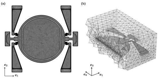
Figure 5.
Computational domains for Micromirror 1: upper view of (a) and internal cut section of generated with an plane passing through the centre of the box (b).

Table 2.
Number of elements and number of nodes associated with solid, fluid, and full domain triangulation for Micromirror 1.
The pressure field at a given instant is depicted in Figure 6 while the time evolution of the magnitude of the fluid velocity is displayed in Figure 7, for . In particular, these plots highlight the complex flow pattern developing around the mirror as vortex shedding becomes evident and strongly impacts on dissipation in the flow. The numerically computed quality factor Q is compared with the experimental estimates obtained by applying the approximate Davis’s [23] formulas to the curves in Figure 3. The hypothesis for Davis’s formulas are almost satisfied as the fluid motion is non-chaotic and it is reasonable to assume either linear or quadratic damping [53]. On the other hand, we can take as a good approximation the third order nonlinearity, even if the real nonlinearity of the system has a different trend (see discussions in [29]).

Figure 6.
Pressure field [Pa] for Micromirror 1 in a section generated by the plane passing through the centre of the box at for (a), and (b).
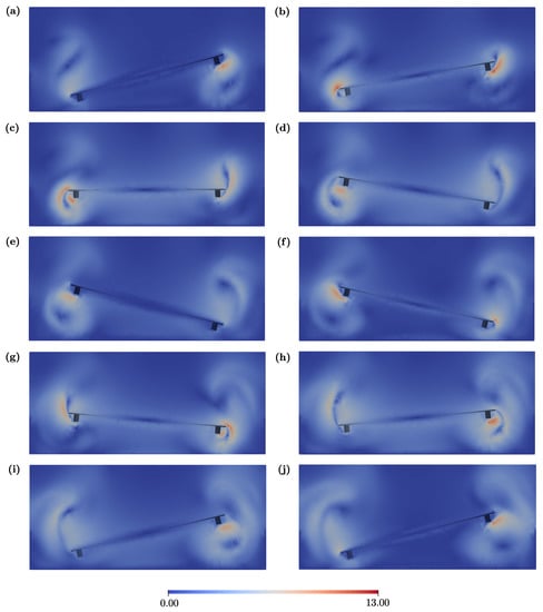
Figure 7.
Magnitude of fluid velocity [m/s] for Micromirror 1 in a section generated by the plane passing through the centre of the box for . The plots refer to various instants along the period: /10 (a), /5 (b), 3/10 (c), 2/5 (d), /2 (e), 3/5 (f), 7/10 (g), 4/5 (h), 9/10 (i), and (j).
The numerical method predicts the correct trend of the experimental quality factor, as reported in Table 3 and in Figure 8. The error percentage between Davis’s formula and numerical results is about 10–17%, with an increasing gap for large oscillations. In particular, as mentioned before, can not be simulated with the ALE approach, thus the Q factor is extrapolated with a cubic spline for the sake of completeness. It is worth stressing that the dependence of Q on the maximum amplitude is strongly nonlinear with fourfold variations between the smallest and the largest angle taken into account in the simulation phase.

Table 3.
Collection of Q factors for Micromirror 1. For each amplitude, the table reports the value of Q obtained from experimental data, the value of Q extracted from the numerical simulation, and the percentage relative error of numeric Q with respect to experimental Q. Data annotated with an asterisk denote quantities that have been extrapolated and not computed through numerical simulation.
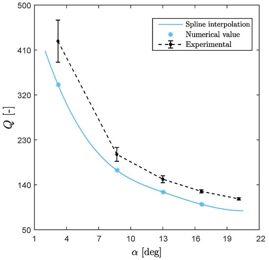
Figure 8.
Comparison between experimental and numerical quality factors for Micromirror 1. The dependence of Q on the maximum aperture is strongly nonlinear.
In order to critically assess the validity of the numerical analyses, firstly a mesh dependence analysis has been carried out for Micromirror 1, with the maximum amplitude . The results are collected in Figure 9 and the estimated quality factor shows a negligible variation with respect to the number of nodes for sufficiently refined meshes.
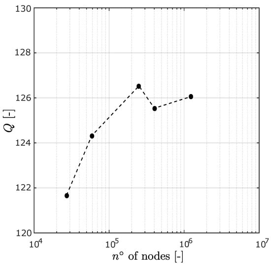
Figure 9.
Mesh convergence analysis in Micromirror 1 for , with a semilogarithmic scale on the abscissa. We highlight that the computed quality factor does not show a remarkable dependence on the mesh refinement, hence suggesting that the analysis has reached convergence.
Finally, with the purpose of better understanding the origin of the strong nonlinear dependence of Q on the maximum amplitude, we compute the component along the rotation axis of the torque exerted by the fluid forces on the reflective surface of the micromirror. Although the micromirror does not undergo a rigid deformation, we evaluate this torque function under the assumption that the deformability of the reflecting surface is negligible. In Figure 10 we present the time history of the torque function computed for each maximum opening amplitude. Moreover, we plot separately the first in phase and anti-phase Fourier components as the latter is responsible for generating dissipation. Some comments are worth stressing. First, the torque evolution reaches the steady state almost instantaneously, thus justifying the choices made in previous analyses. Secondly, the anti-phase component increases more than linearly with respect to the opening angle, thus explaining the strong nonlinear behaviour of Q. From a physical standpoint this can be associated with a complete change in the fluid response pattern with the appearance of important vorticity.
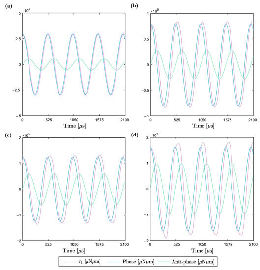
Figure 10.
Component along of the torque computed on the reflective surface of Micromirror 1. This function is periodic with frequency and with magnitude that increases along with the maximum amplitude of micromirror. Moreover, is decomposed into phase and anti-phase components with respect to the mirror rotation by applying a first order Fourier decomposition. The results are presented for (a), (b), (c), and (d). Results show that an increasing phase shift appears at large oscillation amplitudes.
4.2. Micromirror 2
The proposed procedure is further validated on Micromirror 2, which represents a tough benchmark. Indeed, in this case, the rotation axis is not a-priori fixed due to the presence of the gimbal, and correctly accounting for the actual deformation of the mirror is crucial. The meshes adopted for the numerical simulation of Micromirror 2 are illustrated in Figure 11. They are made of 363,328 quadratic wedge elements, with a subdivision between solid, fluid and full domains as illustrated in Table 4.
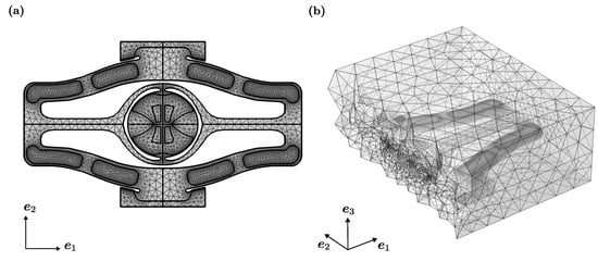
Figure 11.
Computational domains for Micromirror 2: upper view of (a) and internal cut section of generated with an plane passing through the centre of the box (b).

Table 4.
Number of elements and number of nodes associated with solid, fluid, and full domain triangulation for Micromirror 2.
A representative pressure field is depicted in Figure 12. In this case, the match between experimental and numerical values is excellent, with a maximum percentage error of about , as reported in Table 5 and in Figure 13. Moreover, the dependence of the quality factor on the maximum aperture angle is almost linear. It should be noted, however, that the range of the maximum opening angle is considerably smaller than for Micromirror 1.

Figure 12.
Pressure field [Pa] for Micromirror 2 in a section generated by the plane passing through the centre of the box at for (a), and (b).

Table 5.
Collection of Q factors for Micromirror 2. For each amplitude, the table reports the value of Q obtained from experimental data, the value of Q extracted form the numerical simulation, and the percentage relative error of numeric Q with respect to experimental Q.
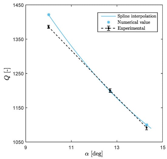
Figure 13.
Comparison between experimental and numerical quality factors for Micromirror 2. The dependence of Q with respect to maximum amplitude is almost linear.
5. Conclusions
In this paper, a finite element Chorin-Temam fractional step method has been employed to solve fluid dynamic problems characterised by the motion of the MEMS with an Arbitrary Eulerian Lagrangian approach. Moreover, a SUPG stabilisation was implemented and coupled with a specific mesh displacement law. For the purpose of this work, a dedicated numerical solver was developed and 3D fluid dynamics problems were successfully simulated whereby the kinetic energy and the dissipated power during its oscillatory motion were extracted in order to obtain a numerical estimate of the quality factor.
Two types of micromirrors have been studied by modelling both the reflective surface (disk plus reinforcement) and the suspension torsional springs and gimbal. We performed analyses for different maximum aperture angles of the devices. The results obtained with Micromirror 1 show that the numerical Q factor underestimates the experimental one, with a relative error of at low amplitude, while at larger angles the difference increases to due to a stronger nonlinear behaviour. For Micromirror 2, the numerical Q factor slightly overestimates the experimental data, with a maximum relative error of 3%. In general, the numerical trends match the experimental results, in the limit of numerical errors.
Although we do not have a conclusive explanation for the difference in the accuracy of the numerical simulation results for the two mirrors, the following assumptions introduced in the proposed numerical technique have to be noted: (i) in this work we have only addressed a one-way FSI problem, assuming that the fluid forces will not meaningfully modify the deformed shape of the mirror. Micromirror 1, which is larger and thinner, might start violating this assumption more than the small and stiff Micromirror 2; (ii) experimental data have been elaborated using Davis’ formula which is approximate and assumes a linear form of the dissipation in the fluid and a cubic type of nonlinearity for the structure, which can be criticised in view of the discussion in [29]; (iii) The fluid is treated as incompressible. Removing this constraint in the Navier-Stokes equations would make simulations more realistic; (iv) Finally, slip boundary conditions on micromirror surfaces might decrease the dissipation and increase the quality factor, even if marginally. All these points are currently being investigated.
Author Contributions
Conceptualization, A.O., R.C. and A.F.; methodology, A.O., M.C. and A.F.; software, D.D.C. and A.O.; validation, D.D.C. and A.O.; formal analysis, D.D.C.; writing—original draft preparation, D.D.C., M.C. and A.F.; writing—review and editing, D.D.C., A.O., M.C., R.C. and A.F.; supervision, M.C. and A.F.; funding acquisition, A.F. All authors have read and agreed to the published version of the manuscript.
Funding
This research received no external funding.
Data Availability Statement
No new data were created or analyzed in this study. Data sharing is not applicable to this article.
Conflicts of Interest
The authors declare no conflict of interest.
References
- Vigna, B.; Ferrarini, P.; Villa, F.F.; Lasalandra, E.; Zerbini, S. Silicon Sensors and Actuators: The Feynman Roadmap, 1st ed.; Springer International Publishing: Cham, Switzerland, 2022. [Google Scholar]
- Frangi, A.; Opreni, A.; Boni, N.; Fedeli, P.; Carminati, R.; Merli, M.; Mendicino, G. Nonlinear response of PZT-actuated resonant micromirrors. J. Microelectromech. Syst. 2020, 29, 1421–1430. [Google Scholar] [CrossRef]
- Opreni, A.; Frangi, A.; Boni, N.; Mendicino, G.; Merli, M.; Carminati, R. Piezoelectric micromirrors with geometric and material nonlinearities: Experimental study and numerical modeling. In Proceedings of the 2020 IEEE SENSORS, Rotterdam, The Netherlands, 25–28 October 2020; pp. 1–4. [Google Scholar]
- Frangi, A.; Guerrieri, A.; Carminati, R.; Mendicino, G. Parametric resonance in electrostatically actuated micromirrors. IEEE Trans. Ind. Electron. 2016, 64, 1544–1551. [Google Scholar] [CrossRef]
- Zega, V.; Frangi, A.; Opreni, A.; Gattere, G. MEMS Resonators: Numerical Modeling. In Proceedings of the Conference of the Italian Association of Theoretical and Applied Mechanics, Palermo, Italy, 15–19 September 2019; pp. 1159–1166. [Google Scholar]
- Zega, V.; Gattere, G.; Koppaka, S.; Alter, A.; Vukasin, G.D.; Frangi, A.; Kenny, T.W. Numerical modelling of nonlinearities in MEMS resonators. J. Microelectromech. Syst. 2020, 29, 1443–1454. [Google Scholar] [CrossRef]
- Frangi, A.; De Masi, B.; Confalonieri, F.; Zerbini, S. Threshold shock sensor based on a bistable mechanism: Design, modeling, and measurements. J. Microelectromech. Syst. 2015, 24, 2019–2026. [Google Scholar] [CrossRef]
- Faraci, D.; Ghisi, A.; Adorno, S.; Corigliano, A. Top-down, multi-scale numerical simulation of MEMS microphones under guided free fall tests. Microelectron. Reliab. 2021, 121, 114129. [Google Scholar] [CrossRef]
- Fedeli, P.; Frangi, A.; Laghi, G.; Langfelder, G.; Gattere, G. Near vacuum gas damping in MEMS: Simplified modeling. J. Microelectromech. Syst. 2017, 26, 632–642. [Google Scholar] [CrossRef]
- Guo, X.; Yi, Y.B.; Pourkamali, S. A finite element analysis of thermoelastic damping in vented MEMS beam resonators. Int. J. Mech. Sci. 2013, 74, 73–82. [Google Scholar] [CrossRef]
- Zega, V.; Opreni, A.; Mussi, G.; Kwon, H.K.; Vukasin, G.; Gattere, G.; Langfelder, G.; Frangi, A.; Kenny, T.W. Thermal stability of DETF MEMS resonators: Numerical modelling and experimental validation. In Proceedings of the 2020 IEEE 33rd International Conference on Micro Electro Mechanical Systems (MEMS), Vancouver, BC, Canada, 18–22 January 2020; pp. 1207–1210. [Google Scholar]
- Frangi, A.; Cremonesi, M.; Jaakkola, A.; Pensala, T. Analysis of anchor and interface losses in piezoelectric MEMS resonators. Sens. Actuators A Phys. 2013, 190, 127–135. [Google Scholar] [CrossRef]
- Manjappa, M.; Pitchappa, P.; Singh, N.; Wang, N.; Zheludev, N.I.; Lee, C.; Singh, R. Reconfigurable MEMS Fano metasurfaces with multiple-input–output states for logic operations at terahertz frequencies. Nat. Commun. 2008, 9, 1–10. [Google Scholar] [CrossRef]
- Piazza, G.; Stephanou, P.J.; Pisano, A.P. Piezoelectric aluminum nitride vibrating contour-mode MEMS resonators. J. Microelectromech. Syst. 2006, 15, 1406–1418. [Google Scholar] [CrossRef]
- Heinrich, S.M.; Dufour, I. Fundamental theory of resonant MEMS devices. In Resonant MEMS: Fundamentals, Implementation, and Application; Wiley: Hoboken, NJ, USA, 2015; pp. 3–28. [Google Scholar]
- Ghaffari, S.; Kenny, T.W. Damping in Resonant MEMS. Reson. Mems Fundam. Implement. Appl. 2015, 55–71. [Google Scholar] [CrossRef]
- Klose, T.; Sandner, T.; Schenk, H.; Lakner, H. Extended damping model for out-of-plane comb driven micromirrors. In MOEMS Display, Imaging, and Miniaturized Microsystems IV; SPIE Proceedings Series 6114; SPIE: Bellingham, WA, USA, 2006; pp. 184–195. [Google Scholar]
- Sandner, T.; Klose, T.; Wolter, A.; Schenk, H.; Lakner, H. Damping analysis and measurement for a comb-drive scanning mirror. In MEMS, MOEMS, and Micromachining; SPIE Proceedings Series 5455; SPIE: Bellingham, WA, USA, 2005; pp. 147–158. [Google Scholar]
- Peng, M.; Zhu, X.; Jiang, B.; Zhou, T.; Su, Y. Air damping characteristics of a 2D MEMS electromagnetically driven micro-mirror. Microsyst. Technol. 2019, 25, 2675–2682. [Google Scholar] [CrossRef]
- Farrugia, R.; Portelli, B.; Grech, I.; Camilleri, D.; Casha, O.; Micallef, J.; Gatt, E. Air damping of high performance resonating micro-mirrors with angular vertical comb-drive actuators. Microsyst. Technol. 2022, 28, 1451–1465. [Google Scholar] [CrossRef]
- Farrugia, R.; Grech, I.; Camilleri, D.; Micallef, J.; Casha, O.; Gatt, E. CFD Analysis of Aerodynamic Drag on Resonating MEMS Micro-Scanners. In Proceedings of the 2019 Symposium on Design, Test, Integration & Packaging of MEMS and MOEMS (DTIP), Paris, France, 12–15 May 2019; pp. 1–4. [Google Scholar]
- Farrugia, R.; Portelli, B.; Grech, I.; Micallef, J.; Casha, O.; Gatt, E. Design and Fabrication of High Performance Resonant Micro-Mirrors using the Standard SOIMUMPs Process. In Proceedings of the 2020 Symposium on Design, Test, Integration & Packaging of MEMS and MOEMS (DTIP), Lyon, France, 15–26 June 2020; pp. 1–6. [Google Scholar]
- Davis, W.O. Measuring Quality Factor From a Nonlinear Frequency Response With Jump Discontinuities. J. Microelectromech. Syst. 2011, 20, 968–975. [Google Scholar] [CrossRef]
- Frangi, A.; Gobat, G. Reduced order modelling of the nonlinear stiffness in MEMS resonators. Int. J. Nonlinear Mech. 2019, 116, 211–218. [Google Scholar] [CrossRef]
- Gobat, G.; Zega, V.; Fedeli, P.; Guerinoni, L.; Touzé, C.; Frangi, A. Reduced order modelling and experimental validation of a MEMS gyroscope test-structure exhibiting 1:2 internal resonance. Sci. Rep. 2021, 11, 1–8. [Google Scholar] [CrossRef] [PubMed]
- Opreni, A.; Furlan, M.; Bursc, A.; Boni, N.; Mendicino, G.; Carminati, R.; Frangi, A. One-to-one internal resonance in a symmetric MEMS micromirror. Appl. Phys. Lett. 2022, in press.
- Donea, J.; Huerta, A.; Ponthot, J.-P.; Rodríguez-Ferran, A. Arbitrary Lagrangian-Eulerian methods. Encycl. Comput. Mech. 2004, 1, 413–437. [Google Scholar]
- Bottasso, C.L.; Detomi, D.; Serra, R. The ball-vertex method: A new simple spring analogy method for unstructured dynamic meshes. Comput. Methods Appl. Mech. Eng. 2005, 194, 4244–4264. [Google Scholar] [CrossRef]
- Opreni, A.; Vizzaccaro, A.; Frangi, A.; Touzé, C. Model order reduction based on direct normal form: Application to large finite element MEMS structures featuring internal resonance. Nonlinear Dyn. 2021, 105, 1237–1272. [Google Scholar] [CrossRef]
- Vizzaccaro, A.; Opreni, A.; Salles, L.; Frangi, A.; Touzé, C. High order direct parametrisation of invariant manifolds for model order reduction of finite element structures: Application to large amplitude vibrations and uncovering of a folding point. Nonlinear Dyn. 2022, 110, 525–571. [Google Scholar] [CrossRef]
- Opreni, A.; Vizzaccaro, A.; Touzé, C.; Frangi, A. High order direct parametrisation of invariant manifolds for model order reduction of finite element structures: Application to generic forcing terms and parametrically excited systems. Nonlinear Dyn. 2022. [Google Scholar] [CrossRef]
- Opreni, A.; Vizzaccaro, A.; Boni, N.; Carminati, R.; Mendicino, G.; Touzé, C.; Frangi, A. Fast and accurate predictions of mems micromirrors nonlinear dynamic response using direct computation of invariant manifolds. In Proceedings of the 2022 IEEE 35th International Conference on Micro Electro Mechanical Systems Conference (MEMS), Seoul, Korea, 16–20 May 2022; pp. 491–494. [Google Scholar]
- Frangi, A.; Guerrieri, A.; Boni, N. Accurate simulation of parametrically excited micromirrors via direct computation of the electrostatic stiffness. Sensors 2017, 17, 779. [Google Scholar] [CrossRef] [PubMed]
- Schenk, H.; Dürr, P.; Kunze, D.; Lakner, H.; Kuck, H. A resonantly excited 2D-micro-scanning-mirror with large deflection. Sens. Actuators A Phys. 2001, 89, 104–111. [Google Scholar] [CrossRef]
- Opreni, A.; Boni, N.; Carminati, R.; Frangi, A. Analysis of the nonlinear response of piezo-micromirrors with the harmonic balance method. Actuators 2021, 10, 21. [Google Scholar] [CrossRef]
- Hopcroft, M.A.; Nix, W.D.; Kenny, T.W. What is the Young’s Modulus of Silicon? J. Microelectromech. Syst. 2010, 19, 229–238. [Google Scholar] [CrossRef]
- Frangi, A.; Guerrieri, A.; Boni, N. nonlinear dynamics in torsional micromirrors. In Proceedings of the 13ème Colloque National en Calcul des Structures, Presqu’île de Giens (Var), France, 15–19 May 2017. [Google Scholar]
- Mirzazadeh, R.; Mariani, S.; Ghisi, A.; De Fazio, M. Fluid damping in compliant, comb-actuated torsional micromirrors. In Proceedings of the 2014 15th International Conference on Thermal, Mechanical and Mulit-Physics Simulation and Experiments in Microelectronics and Microsystems (EuroSimE), Ghent, Belgium, 7–9 April 2014; pp. 1–7. [Google Scholar]
- Quarteroni, A.; Valli, A. Numerical Models for Differential Problems, 2nd ed.; Springer: Milan, Italy, 2014. [Google Scholar]
- Guzmán, J.; Salgado, A.J.; Sayas, F.J. A note on the Ladyženskaja-Babuška-Brezzi condition. J. Sci. Comput. 2013, 56, 219–229. [Google Scholar] [CrossRef][Green Version]
- Fujima, S. Iso-p2 p1/p1/p1 domain-decomposition/finite-element method for the navier-stokes equations. Contemp. Math. 1998, 218, 246–253. [Google Scholar]
- Koubaiti, O.; Elkhalfi, A.; El-Mekkaoui, J.; Mastorakis, N. Solving the problem of constraints due to Dirichlet boundary conditions in the context of the mini element method. Int. J. Mech 2020, 14, 12–22. [Google Scholar]
- Carstensen, C.; Sauter, S. Critical functions and inf-sup stability of Crouzeix-Raviart elements. Comput. Math. Appl. 2022, 108, 12–23. [Google Scholar] [CrossRef]
- Chorin, A.J. The numerical solution of the Navier-Stokes equations for an incompressible fluid. Bull. Am. Math. Soc. 1967, 73, 928–931. [Google Scholar] [CrossRef]
- Temam, R. Approximation of the solution of the Navier- Stokes equations by the fractional step method (Approximate solution method for Navier-Stokes equations for incompressible viscous fluids). Arch. Ration. Mech. Anal. 1969, 32, 135–153. [Google Scholar]
- Blasco, J.; Codina, R.; Huerta, A. A fractional-step method for the incompressible Navier–Stokes equations related to a predictor–multicorrector algorithm. Int. J. Numer. Methods Fluids 1998, 28, 1391–1419. [Google Scholar] [CrossRef]
- Codina, R. Pressure stability in fractional step finite element methods for incompressible flows. J. Comput. Phys. 2001, 170, 112–140. [Google Scholar] [CrossRef]
- Tobiska, L.; Lube, G. A modified streamline diffusion method for solving the stationary Navier-Stokes equation. Numer. Math. 1991, 59, 13–29. [Google Scholar] [CrossRef]
- Bezanson, J.; Karpinski, S.; Shah, V.; Edelman, A. Julia Language Documentation. The Julia Manual. 2014; pp. 1–261. Available online: http://docs.julialang.org/en/release-0.2/manual (accessed on 9 September 2022).
- Comsol, A.B. COMSOL Multiphysics User’s Guide. 2005. Available online: https://extras.csc.fi/math/comsol/3.4/doc/multiphysics/wwhelp/wwhimpl/js/html/wwhelp.htm?context=multiphysics&file=html_guideintro.5.1.html (accessed on 9 September 2022).
- Squillacote, A.H.; Ahrens, J.; Law, C.; Geveci, B.; Moreland, K.; King, B. The Paraview Guide; Kitware Clifton Park: New York, NY, USA, 2007. [Google Scholar]
- Higham, D.J.; Higham, N.J. MATLAB Guide; SIAM: Philadelphia, PA, USA, 2016. [Google Scholar]
- Nabholz, U.; Heinzelmann, W.; Mehner, J.E.; Degenfeld-Schonburg, P. Amplitude-and gas pressure-dependent nonlinear damping of high-Q oscillatory MEMS micro mirrors. J. Microelectromech. Syst. 2018, 27, 383–391. [Google Scholar] [CrossRef]
Publisher’s Note: MDPI stays neutral with regard to jurisdictional claims in published maps and institutional affiliations. |
© 2022 by the authors. Licensee MDPI, Basel, Switzerland. This article is an open access article distributed under the terms and conditions of the Creative Commons Attribution (CC BY) license (https://creativecommons.org/licenses/by/4.0/).