1. Introduction
Being an essential part of vehicles, the suspension system plays a vital role in improving handling stability and ride comfort. Intensive studies on vehicle suspensions have driven their evolution from passive systems to semi-active or active ones. Passive suspension systems are simple and cheap [
1,
2,
3], but they cannot be adapted to complex road conditions. Active suspension systems [
4,
5,
6] use actuators instead of conventional springs and damping elements to control output forces online and are able to significantly improve vibration suppression, but high costs and energy consumption limit their widespread use in vehicle suspensions. Semi-active suspensions have become a hot topic in this research field because they can be considered as a compromise between passive and active suspension systems by varying the parameters of adjustable components to improve the suspension’s performance [
7,
8] without consuming significant energy.
With the development of suspension systems, several semi-active control strategies have been proposed to meet the requirement for ride comfort. One classic control algorithm is the skyhook damping control strategy [
9], which has been intensively studied since its appearance. Du et al. [
10] proposed an adaptive skyhook control (ASC) based on an improved Genetic Algorithm (GA), which effectively reduced the vehicle body acceleration under different driving speeds. Ma et al. [
11] designed an optimized fuzzy skyhook controller with a gray wolf optimizer (GWO) algorithm, with results showing that body acceleration was significantly reduced under different road conditions. Although the canopy damping control is effective in improving the ride comfort under varying road conditions and velocities, it does not consider the influence of vehicle load changes on ride comfort, implying that it cannot realize dynamic tire load, thus reducing the handling stability [
12].
Inerter was first introduced by Smith [
13] in 2002 as a two-terminal element, in which the force applied to the two terminals is proportional to the relative acceleration between them. The scale factor is called the inertance coefficient and is measured in kilograms. In subsequent research, some scholars have applied inerter to vehicle suspensions, forming new suspension systems with damper and spring, i.e., the inerter–spring–damper (ISD) [
14,
15,
16,
17] suspension systems. Moreover, it has been found that the inerter can add fixed virtual mass to the sprung mass, thereby reducing the inherent frequency to improve ride comfort [
18,
19,
20]. Nevertheless, a passive inerter is a non-active component whose inertance coefficients cannot be adjusted online, and it has limited ability in improving the vehicle suspension performance. As research progresses, semi-active inerters and control strategies have been gradually proposed, with the increasingly common use of semi-active inertance control in suspensions. Chen et al. [
21,
22] studied the application of adjustable inerters in semiactive suspensions and designed a semi-active inerter to illustrate the necessity and benefits of introducing semi-active inerters in suspensions. Wang [
23] proposed a semi-active inerter control strategy for relative acceleration relative velocity control (RARV) and applied it to vehicle suspensions. Simulation results show that such a control strategy can achieve better performance indicators. Hu [
24] presented a skyhook inertance control strategy which adds a virtual mass to the sprung mass to improve ride comfort. Zhang [
25] combined skyhook inertance and the damping control strategy to propose three double-skyhook control strategies, and their results show that all three control strategies can enhance ride comfort, with the damping-based control strategy having the best performance.
While the double-skyhook control strategy guarantees riding comfort, it ignores the effect of dynamic tire load. The concept of groundhook damping control [
26] is to install a damper between the ground reference and the unsprung mass, and its semi-active simulation results show that groundhook damping control can significantly suppress dynamic tire loads. In this paper, three semi-active control strategies are proposed to improve ride comfort and handling stability by combining the skyhook damping, skyhook inertance and groundhook damping controls. The proposed strategies are conducted with semi-active devices such as a damper or an inerter, or a combination thereof. The former is named as the independent multi-hook control (Ma), the latter is the combined multi-hook control, which can be further divided into the inertance-based (Mb) and damping-based (Mc) multi-hook controls according to whether the semi-active device is dominated by the inertance or damping. The results demonstrate that the combined control strategy can not only make the vehicle adapt to road and load conditions but also ensure appropriate handling stability.
The following content is organized as follows. In
Section 2, the multi-hook configuration is introduced and the benefits of this configuration are qualitatively analyzed. In
Section 3, two semi-active realizations of the multi-hook controls, including the independent multi-hook control and the combined multi-hook control, are investigated separately, and then three multi-hook control strategies are illustrated based on a quarter-car model. In
Section 4, numerical simulations and analyses of the multi-hook control strategies are performed based on the verified model. Conclusions are drawn in
Section 5.
2. Performance Benefits of the Multi-Hook System
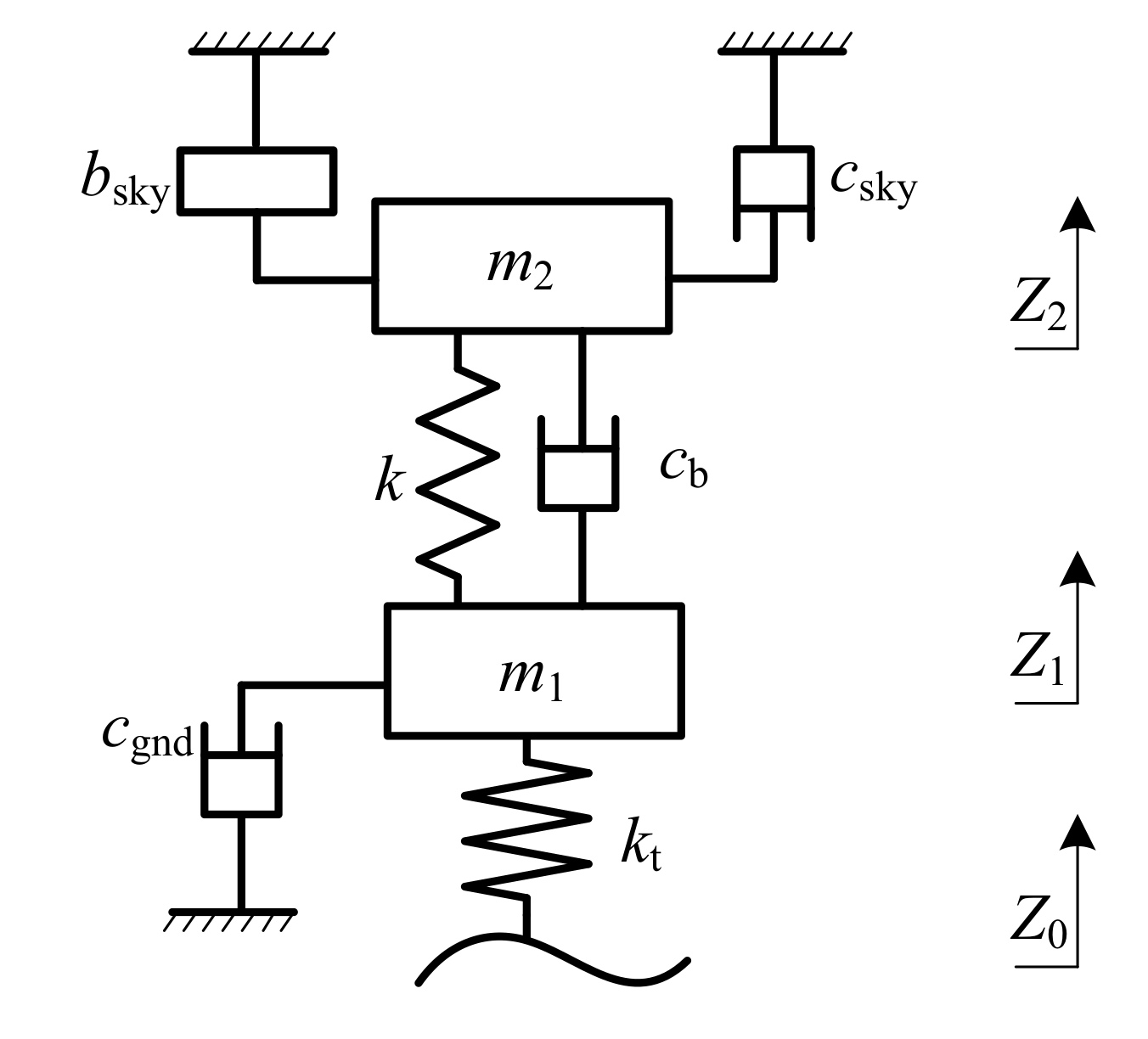
A degree-of-freedom (DOF) model of the multi-hook system is shown in
Figure 1, where
and
represent the sprung mass and unsprung mass, respectively.
represents the inertance of the virtual inerter;
and
are the damping coefficients of the virtual damper, in which
means the damper is inserted between the stationary sky (the imaginary reference frame) and the sprung mass, while
means the damper is inserted between the stationary ground and the unsprung mass. A spring with the stiffness coefficient
k and a damper with the damping coefficient
are settled between the unsprung mass and sprung mass. The tire is modeled by a spring with the stiffness coefficient
. In this model,
(resp.,
) is the vertical displacement of
(resp.,
) and
is the road profile.
In the multi-hook configuration, the skyhook inerter is capable of simulating part of the sprung mass; the skyhook damper is used to suppress the vertical vibration of the body; and the groundhook damper is used to suppress the wheel runout. With the multi-hook system, the ride comfort is improved by reducing the acceleration and velocity of the sprung mass, and the handling stability is ensured by lowering the dynamic tire load. The skyhook damping force
, the skyhook inertance force
and the groundhook damping force
can be expressed as:
The equations of motion for the multi-hook suspension system are as follows:
where
is called the damping force of basic damper and is denoted by
.
2.1. Load Adaptation
Equation (
2) can be rewritten as:
where
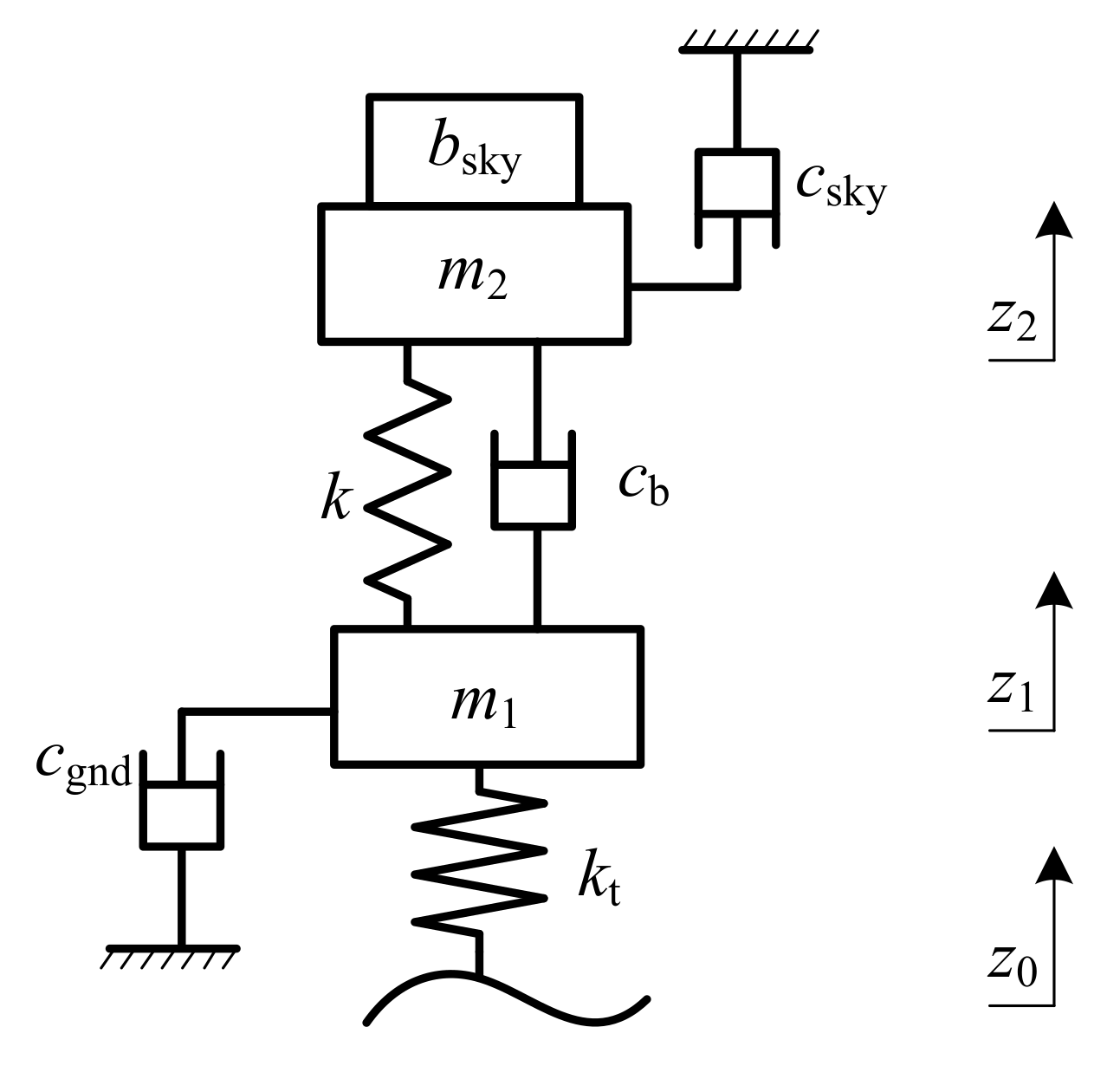
is taken as a combined sprung mass, which is connected to a skyhook damper, as shown in
Figure 2. This means
can simulate part of the sprung mass, so it can be adjusted online according to Equation (
4) to keep the system at a virtually full load at all times. In this way, even if the load condition changes, the system can always obtain the same performance at full-load conditions. These guarantee the multi-hook system to have good load adaptability. Thus, one has:
where
is the full-load mass.
2.2. Road Condition Adaptability
Under different road conditions, the skyhook damping needs to be adjusted online to ensure the suspension operation, so that the car can continuously obtain the ideal performance with excellent road adaptability. According to previous studies, the system damping ratio can be used as the control quantity [
27,
28], which can be calculated as:
Considering the requirements of ride comfort and handling stability, the system damping ratio should be controlled between the comfort damping ratio
and the safety damping ratio
, where the optimal damping ratio is determined [
28].
and
are calculated by the following formula:
respectively, where
is the stiffness ratio and
is the mass ratio, and they are expressed as
and
Based on Equation (1), the calculated
can be used as the base damping
for adjusting the skyhook and groundhook damping, then
can be expressed by the following equation:
As is shown in Equation (
10), as road conditions change, the value of
can be adjusted online according to the optimal damping ratio to adapt to this variation, verifying the adaptability of the system to road conditions.
Optimization of the Multi-Hook Parameters under Different Road Conditions
Under different road conditions, vehicles have different requirements to realize dynamic performance. The damping ratios are selected for different road conditions to regulate the and online, so as to guarantee that the vehicle operates in the best state constantly.
Class A roads have better road conditions, so the driving speed on them is generally higher; therefore, the safety damping ratio is chosen to improve driving safety. On class C roads, the road conditions are poor with lower driving speed, so the damping ratio is chosen for comfort damping to improve driving smoothness. A comprehensive damping ratio was selected for class B roads. The obtained simulation conditions are given in
Table 1.
The objective function shown in Equation (
11) transforms the multi-objective optimization problem into a single-objective optimization.
respectively, where
,
and
are the root mean square (RMS) values of the body acceleration, suspension working space and dynamic tire load of the ideal multi-hook suspension system;
,
and
are the RMS of the corresponding performance indicators of the passive suspension under the same vehicle speed and road conditions. The weight coefficients
,
and
are determined from the variations of road conditions and vehicle speed as shown in
Table 2, based on which, the coefficients
and
were optimized for different road classes using a genetic algorithm, and the results are shown in
Table 3.
2.3. Handling Stability
The skyhook damping control strategy is widely used in conventional semi-active suspension systems, but it inevitably leads to the deterioration of handling stability. Consequently, based on the introduction of skyhook damping and inertance, the structure of groundhook damping is added to reduce the vibration of unsprung mass by providing a reverse force that is proportional to its absolute velocity. In this way, the handling stability is improved. The grounded damping force can be calculated by
One limitation is that the multi-hook system described above is only an ideal configuration. It is not feasible to connect the damper and inerter to the static reference frame. Hence, the realization of control systems should be implemented via a semi-active or active actuator.
3. Semi-Active Realization of the Multi-Hook Control
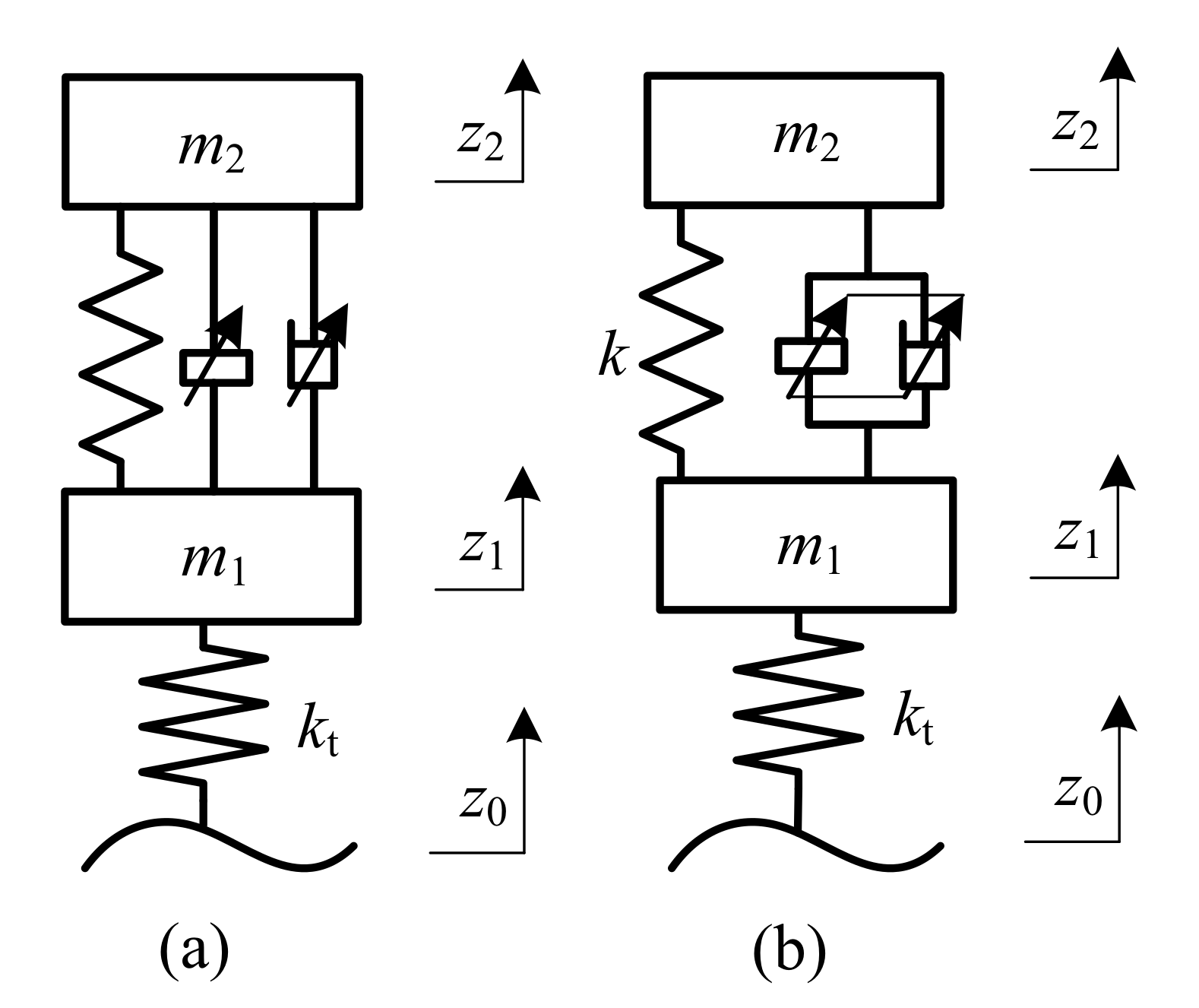
In this section, two semi-active implementation methods of multi-hook control systems are proposed: one adopts an adjustable damper and an adjustable inerter, which are independent of each other, as shown in
Figure 3a, and another adopts a semi-active device combining an adjustable damper and inerter, as shown in
Figure 3b.
The equations of motion of the semi-active suspensions shown in
Figure 3 can be expressed as:
where
and
are the inertance and the damping coefficients, respectively, and
x is control variable.
and
are the forces provided by the inerter and damper, respectively, which are marked as
and
, respectively.
It should be noted that there are differences between the semi-active suspension and ideal multi-hook system, so two coefficients, i.e.,
and
, are introduced to make the multi-hook control strategy better adapted to the changes in road conditions. The adjustable inertance force
and the adjustable damping force
can be calculated as
where
where
is the damping distribution coefficient, which ranges from 0 to 1. It represents the proportion of the skyhook damping in the sum of the skyhook and groundhook damping
. When
= 0, there is only the groundhook damping; when
b = 1, only skyhook damping is controlled. Considering that an appropriate increase in the proportion of the groundhook damping is beneficial to restrain the tire vibration,
is set as 0.3 in this paper.
In
Figure 3a,
and
should be, respectively, equal to
and
to realize the ideal structure. That is
For the configuration in
Figure 3b, the resultant forces of
and
are set equal to those of
and
.
Based on this classification, two control strategies of multi-hook control can be given in
Section 3.2 and
Section 3.3.
3.1. Optimization of the Damping Gain Factor
As the dynamic tire load inevitably deteriorates during the semi-active realization of the skyhook damping,
,
are optimized for different road conditions by using the MATLAB genetic algorithm toolbox with tire grounding as the optimization objective, and the optimization results are shown in
Table 4.
3.2. Independent Multi-Hook Control
Equation (
15) can be rewritten as
Considering the limitations of the actual device, the control laws of the independent semi-active inerter and damper can be obtained as
respectively, where
The underlining idea of the skyhook inertance control law [
24] Equation (
18) is to make the
transfer
when the semi-active force has the same direction as the skyhook inerter force and transmit the minimal force when the directions are reversed.
and
indicate the maximum and minimum inertance coefficients that can be provided by the semi-active inerter. The idea of the skyhook damping control law Equation (
19) is to make the
transfer
when the velocity of the sprung mass is in the same direction as the relative velocity, taking the minimum damping force when the directions are opposite.
and
indicate the maximum and minimum damping coefficients that can be provided by the semi-active damper.
3.3. Combined Multi-Hook Control
The combined control strategy is implemented by a verified semi-active device designed by our group and verified experimentally, which is characterized by its ability to provide both damping and inertial forces, and whose damping and inertance coefficients are both functions about its spool displacement
x. There exists a ratio relationship between the damping and inertance coefficients [
25], that is
where
is the damping–inertance ratio of the device.
When the coefficient of damping is used as the control variable, it is referred to as the damping-based multi-hook control. When the inertance coefficient is used as the control variable, it is referred to as the inertance-based multi-hook control. According to Equations (
16) and (
20), the inertance-based multi-hook control law is:
in which
The damping-based multi-hook control law is:
respectively, where
4. Simulation and Analysis of Multi-Hook Control Strategies
This section verifies the effectiveness of the proposed multi-hook control strategy by simulation. A light truck is chosen in this simulation, and the parameters of its quarter vehicle model are provided in
Table 5.
4.1. Analysis of Load Adaptability
In this subsection, the performances of passive suspensions and these semi-active suspensions are compared under different loads to verify if semi-active suspensions with multi-hook control are able to adapt to load change as an ideal virtual multi-hook system.
For the passive suspension, the sprung mass is given as 500 kg, 800 kg and 1100 kg at the conditions of no load, half load and full load, respectively. For semi-active suspensions, the corresponding skyhook inertances are set to 600 kg, 300 kg and 0 kg to keep the suspensions at a virtual full-load condition. To simplify presentation, the independent, inertance-based and damping-based multi-hook control are referred to as Ma, Mb and Mc, respectively, in the following.
4.1.1. Frequency Responses to Sinusoidal Excitations
To investigate the performance of the three types of suspensions with multi-hook control strategies under different loads, all damping ratios were set to
. A sine wave
was used as the excitation, where
f ranged from 1 Hz to 100 Hz and
A = 0.1 m s
−1.
Figure 4 compares the RMS of BA for the passive suspension and the semi-active suspensions with multi-hook control strategies at each frequency. The resonant frequencies and the corresponding peak values for each suspension are listed in
Table 6.
As seen from
Table 6, load change has a quite limited effect on the resonant frequency of the unsprung mass for all suspensions, but it mainly affects that of the sprung mass. Furthermore, it can be observed that the variation in the resonant frequency of the sprung mass for the multi-hook semi-active suspension is smaller than for the passive suspension as the load varies, and, in particular, the variations in Mb and Mc for the multi-hook semi-active suspension are extremely slight. In addition to this,
Table 6 indicates that the spring mass resonance frequencies of the semi-active suspension under full load are the same as those of the passive suspension. Seeing from this perspective, the multi-hook control can enable the suspension to approach the suspension performance of the vehicle at full load under different load conditions, which explains why it has the same sprung mass resonance frequency.
On the other hand, the peak RMS values for the semi-active suspension are significantly reduced at low frequencies (resonant frequencies of the sprung mass) and high frequencies (resonant frequencies of the unsprung mass) under all load conditions compared with the passive suspension, as show in
Table 6.
Figure 4 shows that the RMS values of acceleration are reduced across the entire frequency range for all load conditions, which implies that the multi-hook control is capable of simulating full-load conditions and significantly improving ride comfort.
4.1.2. Time Responses to a Random Excitation
On real roads, the response to a random excitation simulates the vehicle. The filtered white noise signal is used as the road input model, that is
where
is road displacement in
m;
is road roughness coefficient in
m
3, which is assumed to be a class
B road in this study. The target vehicle speed
v is set at 20 m s
−1;
is zero-mean Gaussian white noise with intensity 1, and
is low cut-off frequency, which is assumed to be a 0.01 cycle m
−1.
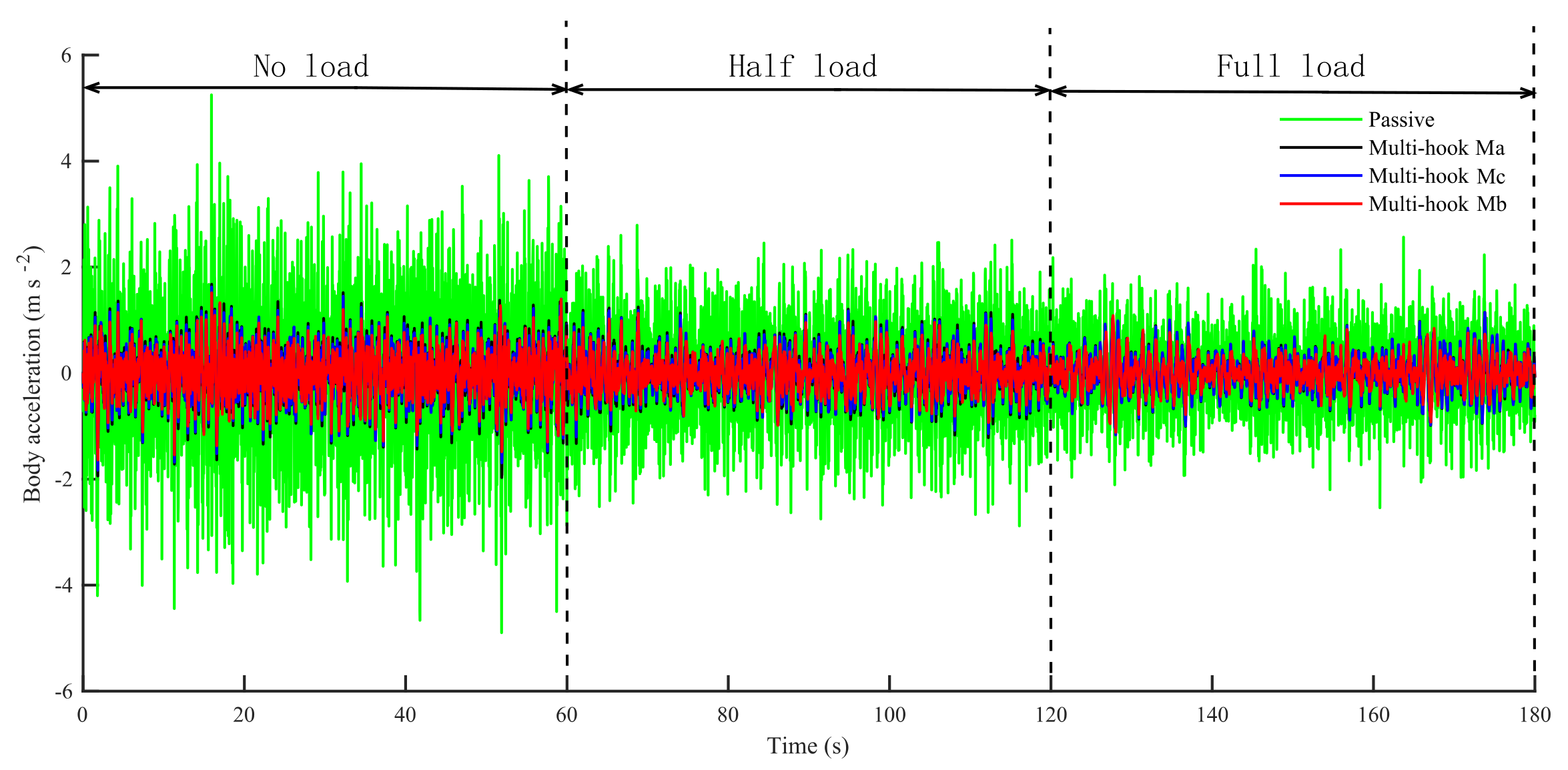
Figure 5 and
Table 7 compare the time domain response of the suspension body acceleration under each load. As can be seen, the ride smoothness of the semi-active suspension using the hybrid shed control is better under all load conditions compared with the passive suspension, especially for the hybrid sheds Mb and Mc.
The RMS values for the BA of the multi-hook semi-active suspension under all loads are less then those for the passive suspension under full load, as seen in
Table 7. When the vehicle is unloaded, the RMS values of BA increase from 0.67 m s
−2 to 1.25 m s
−2 for the passive suspension and from 0.37 m s
−2 to 0.45 m s
−2, from 0.30 m s
−2 to 0.36 m s
−2 and from 0.38 m s
−2 to 0.42 m s
−2 for the multi-hook controls Ma, Mb and Mc, respectively. This means that from full- to no-load, the RMS value of BA for multi-hook control changes less and adapts better to load changes.
4.2. Analysis of Road Condition Adaptability
During simulation, the passive suspension is set to full load. The damping ratio of the passive suspension is set to 0.29 in this paper. The multi-hook semi-active suspension is set to no load, as the semi-active suspension can simulate the full-load condition through canopy inertia control.
The filtered white noise signal shown in Equation (
23) is also used here as the road input model, where the road roughness coefficients
are
m
3 for road class A,
m
3 for road class B and
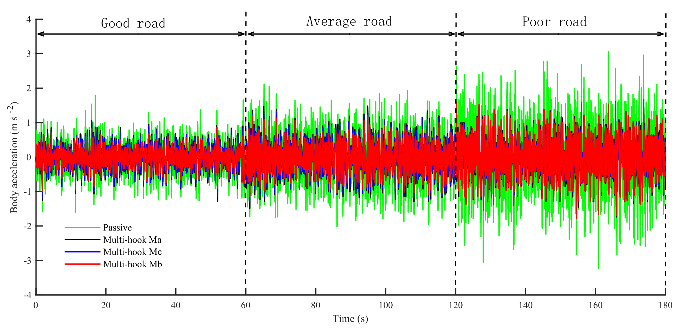
m
3 for road class C, which represent good, average and poor roads, respectively. For comparison purposes, the simulation results for BA under each road condition are placed on the same time domain plot, as shown in
Figure 6. The RMS values for BA are listed in
Table 8.
As observed from
Figure 6, compared with the passive suspension, the semi-active suspensions with the multi-hook control resulted in significant decline in BA under all road conditions, particularly for the multi-hook controls Mb and Mc. These results show that the multi-hook controls are able to offer a high level of ride comfort under different road conditions.
Furthermore, as can be seen from
Table 8, when the vehicle travels from a road with good conditions to a poor one, the RMS values of BA increase from 0.39 m s
−2 to 0.91 m s
−2 for the passive suspension and from 0.28 m s
−2 to 0.53 m s
−2, from 0.21 m s
−2 to 0.54 m s
−2 and from 0.27 m s
−2 to 0.49 m s
−2 for Ma, Mb and Mc, respectively. According to these data, the RMS value variations (max, minus and min) of Ma, Mb and Mc are 51.9%, 36.5% and 57.7% lower than those of the passive suspension, respectively, when road conditions changed from good to bad. This demonstrates that the multi-hook control strategy can adapt to changes in road conditions and provide stable driving comfort, as changes in road conditions have less impact on BA and its RMS value.
4.3. Comparative Analysis of Single-Skyhook and Multi-Hook Control Strategies
Notably, the skyhook damping control, despite being able to enhance road adaptability, can exacerbate vibrations in unsprung masses, which means it can deteriorate an important indicator of road holding, i.e., dynamic tire loads. To investigate the effect of groundhook damping in the multi-hook control strategy in reducing dynamic tire load, this subsection compares the performance between single-skyhook suspensions and multi-hook suspensions. All suspensions were set to no-load conditions to better represent the effect of skyhook inertance on suspension performance.
4.3.1. Time Response Analysis
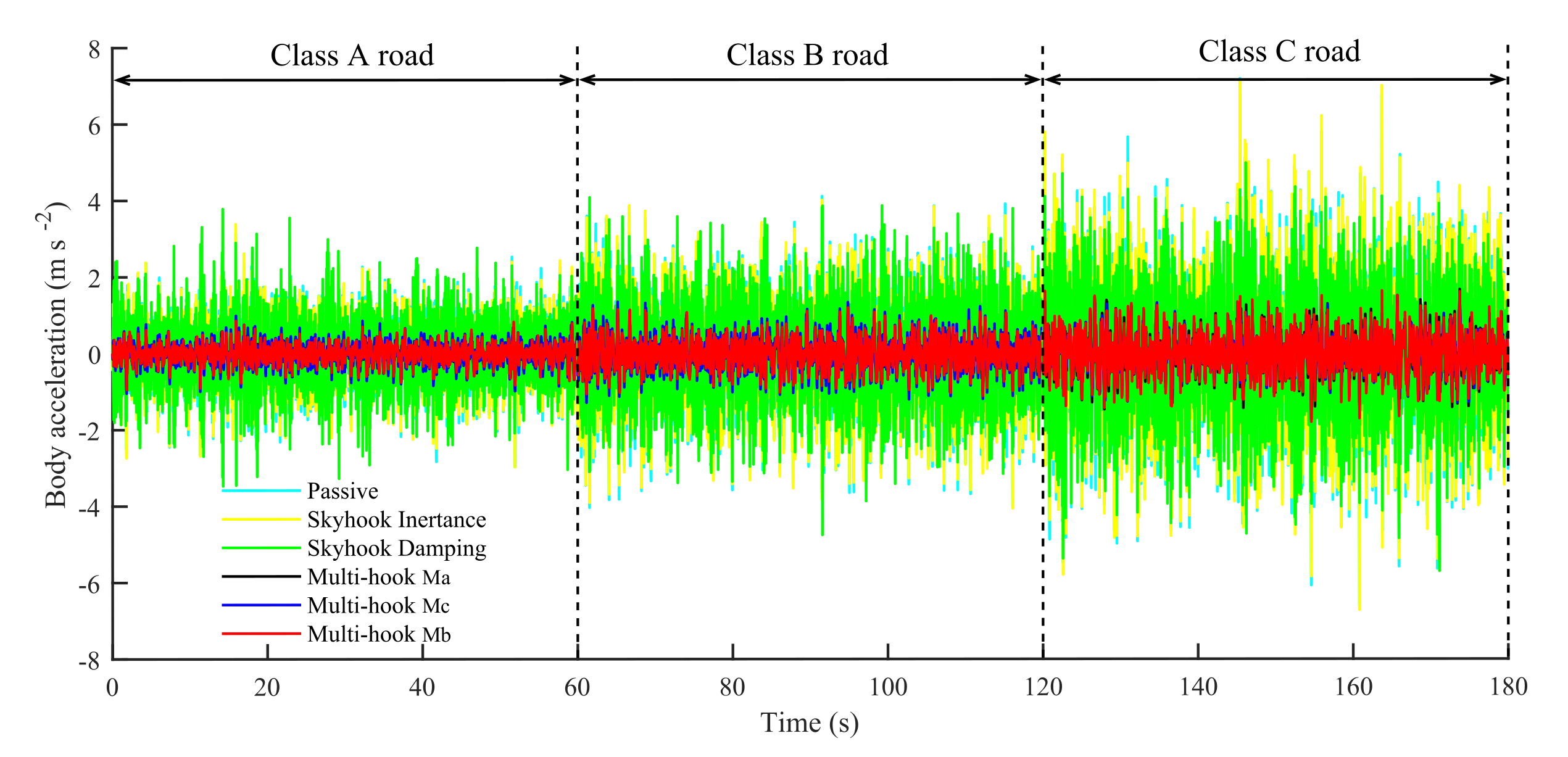
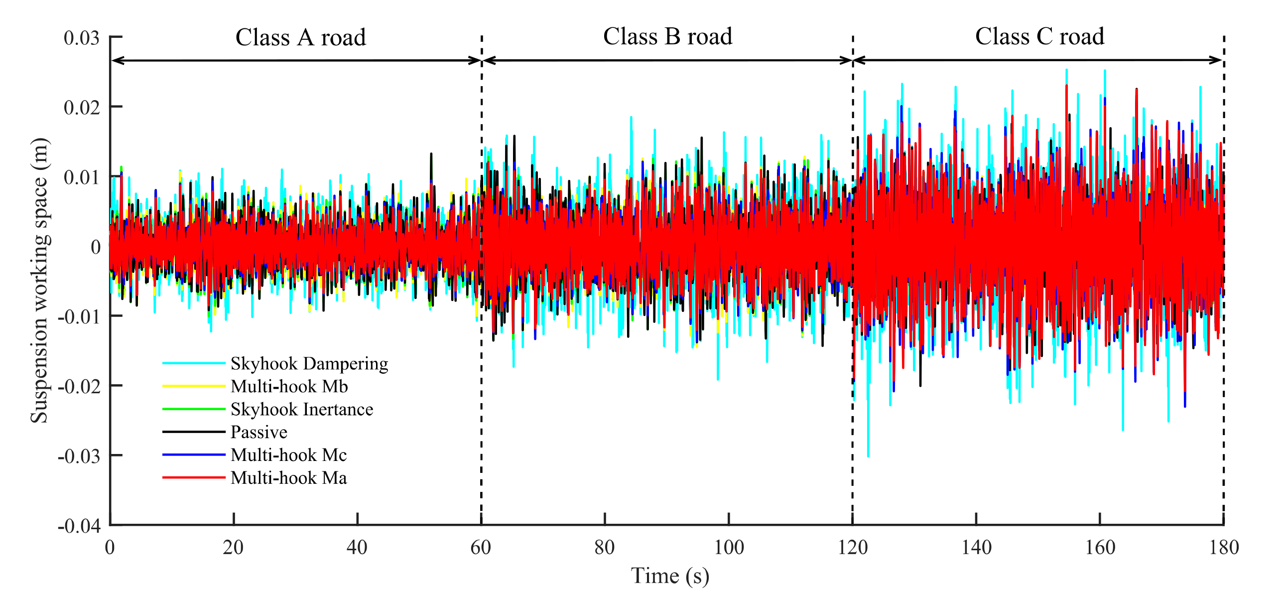
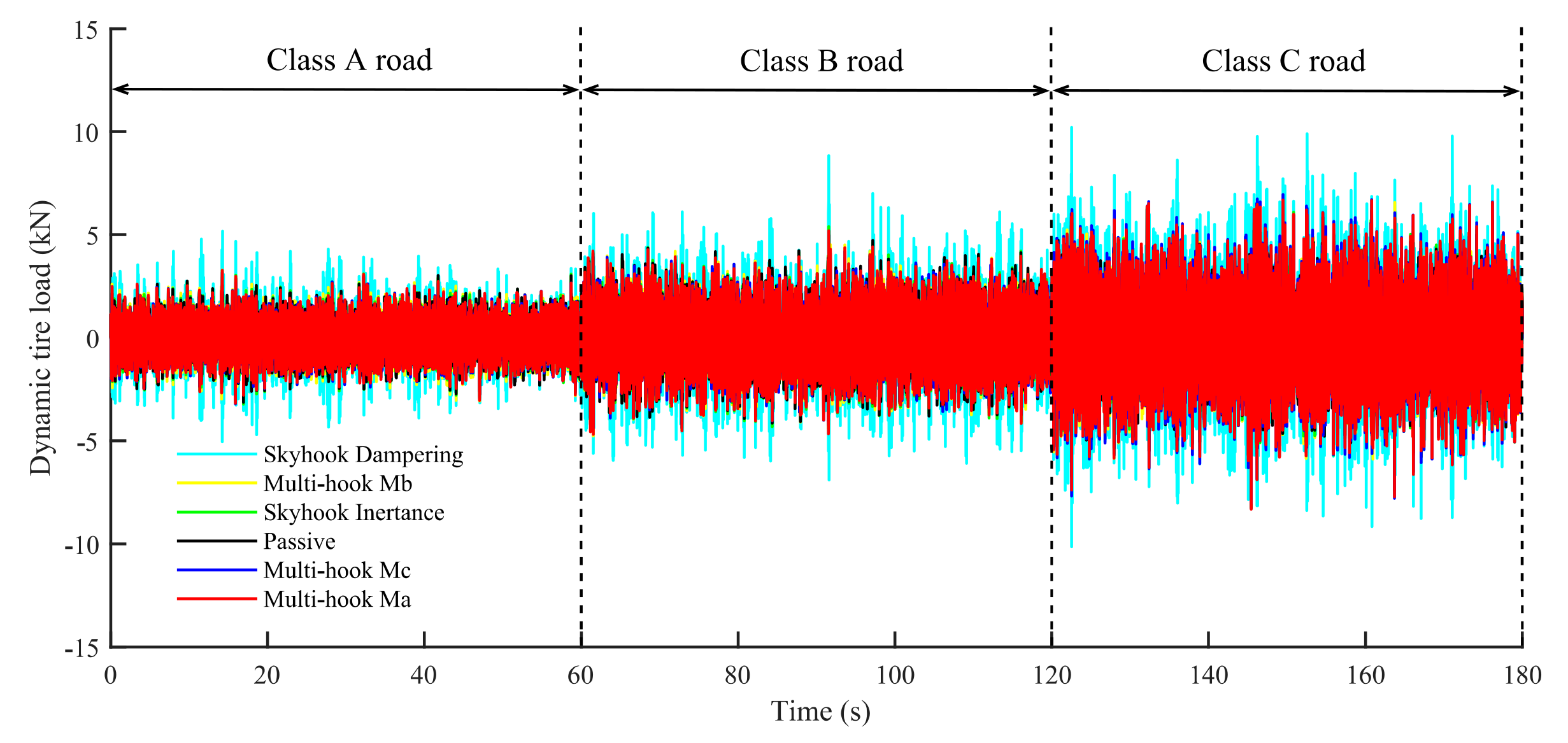
For simulation, the same signals in
Section 4.2 were used as inputs for the road inputs, and all the suspensions were set to no-load. The outputs are the BA and the time domain response of the DTL of each suspension, as shown in
Figure 7,
Figure 8 and
Figure 9. The total RMS values for each suspension indicator are shown in
Table 9. It is clear that the multi-hook-controlled suspension outperforms the single-canopy suspension and the passive suspension. The simulation results show that the multi-hook suspension effectively improves ride smoothness and tire holding. Nevertheless, due to the trade-off between smoothness and safety performance, the operational stability of the inerter-based multi-hook control is slightly worse than that of the skyhook inertance control, but it is still within acceptable limits.
The BA simulation results are transformed by using the FFT technique to obtain the frequency domain response, as shown in
Figure 10. It can be seen that the BA of the multi-hook-controlled suspension outperforms the passive and the single-canopy suspension in the entire frequency domain from 0–15 Hz.
4.3.2. Frequency Response Analysis
Under the same excitation given in
Section 4.1.1, the RMS values of the suspension performance indicators are obtained and shown in
Figure 11. The peak values in the graph are listed in
Table 10.
According to
Figure 11a, the controls with skyhook inerter, i.e., the skyhook inertance control and the multi-hook controls, have smaller natural frequencies of sprung mass than the skyhook damping control. This further verifies that the multi-hook control can simulate full-load conditions. In addition, compared with the skyhook damping control, the low-frequency peak and high-frequency peak of the other four kinds of control are reduced, as shown in
Table 10.
It should be noted that in
Figure 11a, multi-hook controls have smaller BA values than single-skyhook controls in the entire frequency band, meaning that the multi-hook controls are capable of obtaining the desired performance. It can be seen from
Figure 11b and
Table 10 that the SWS values of multi-hook controls are between the skyhook damping and the skyhook inertance controls in the low-frequency band, while in the high-frequency band, these values are the lowest, indicating that the multi-hook controls can make full use of the suspension stroke in the low-frequency band and offer a better ride comfort in the high-frequency band.
Figure 11c and
Table 10 show that the low-frequency peak of Ma is slightly higher than that of the skyhook inertance, but overall, the low- and high-frequency peaks of the multi-hook controls are lower than those of the single-skyhook controls, which is because the introduction of the groundhook damper directly suppresses the vertical vibration of the wheel. In summary, compared with single-skyhook controls, the multi-hook controls can achieve better ride comfort and road holding because they are able to consider both of these factors comprehensively.
