Article

Optimal Design of a Novel Leg-Based Stair-Climbing Wheelchair Based on the Kinematic Analysis of the Stair Climbing States

by
Diego Delgado-Mena
,
Emiliano Pereira
*,
Cristina Alén-Cordero
,
Saturnino Maldonado-Bascón
and
Pedro Gil-Jiménez
Department of Signal Processing and Communications, Universidad de Alcalá, 28001 Madrid, Spain
*
Author to whom correspondence should be addressed.
Actuators 2022, 11(10), 289; https://doi.org/10.3390/act11100289
Submission received: 22 August 2022 / Revised: 26 September 2022 / Accepted: 27 September 2022 / Published: 9 October 2022
(This article belongs to the Special Issue Dynamics and Control of Robot Manipulators)

Abstract

:
This work presents a method to find the optimal configuration of a leg-based stair-climbing wheelchair. This optimization begins with the definition of a high-level control architecture, in which the kinematics restrictions related to the specific obstacles are considered. Then, the reference trajectories for all the actuators are generated as a function of the physical parameters of the mechanism, the dynamic restrictions of the actuators (velocity and acceleration) and the sensor errors. This work illustrates, based on a set of configurations, how the total time to climb up and climb down a defined stair depends on all these parameters, also reporting the best set of parameters that reduces the time and makes the mechanism more stable for a given scenario. The optimization in this work is performed with a brute-force search within a grid of parameters with a resolution of 1 mm. Thus, as the local minima is located, the complexity of the problem is revealed.

1. Introduction

Stair-climbing mechanisms have been researched and developed during the last decades [1]. These mechanisms have been used to assist disabled people [2], to transport other devices such as robots or wheelchairs [3], or to assist devices [4]. All these mechanisms can be classified into (see Table I in [1]): (i) track-based stair-climbing mechanisms, (ii) wheel cluster-based stair-climbing mechanisms, (iii) leg-based stair-climbing mechanisms and (iv) hybrid stair-climbing mechanisms.
Track-based stair-climbing mechanisms have been successfully commercialized. These mechanisms are based on the interlocking effect between the track’s outer teeth and the steps’ sharp corners. TopChair-S [5] proposes a solution based on a caterpillar mechanism, which has a cost of around EUR 15,500. Another commercial solution is the PW-4x4Q Stair-Climbing Wheelchair [2], which is based on large wheels whose relative height can be modified. Its cost is around EUR 12,500. The performance of these solutions depends on the grip of the material on the obstacle, which can deteriorate over time, making the cost of the solution even more expensive due to the maintenance required.
The wheel cluster-based stair-climbing mechanisms are relatively compact and can easily switch to the wheeled mobile mode when running on level ground. Examples of these mechanisms can be found in [6,7], where a cluster of three wheels is proposed. In [6], a mechanism with only one motor and a transmission system per locomotion unit is proposed. The wheelchair passively changes its locomotion, from rolling on wheels (“advancing mode”) to walking on legs (“automatic climbing mode”), according to local friction and dynamic conditions. In [7], a track-based stair-climbing mechanism is combined with the cluster of three wheels in order to improve the wheelchair’s stability. This mechanism has been recently built and used, as reported in [8].
A good example of a hybrid stair-climbing mechanism is the one proposed in [9], which was optimally designed in [10]. This mechanism can be adapted to different steps and obstacles, generating smooth and comfortable trajectories for the user. The control of the mechanism and the improvement in the trajectory generation have been studied in later works [11,12,13].
Leg-based stair-climbing mechanisms can be classified into biped and parallel mechanisms. For example, in [14], a biped stair-climbing mechanism is developed based on a Stewart platform. This mechanism can walk up and down a stair with a riser height of 150 mm, continuously carrying a 60 kg load. A stair-climbing vehicle named “Zero Carrier” with eight legs was proposed in [3]. In [15], the concept of an eight-legged wheelchair, aiming at improving the limitations of the Zero Carrier design, was proposed. The eight legs are grouped into two independent frames of four legs each. Both frames can change the relative horizontal position between them. Thus, the height of the legs can be substantially reduced with respect to the design proposed in [3]. However, the mechanism needed to move the frame horizontally may be inconvenient when heavy loads must be carried.
According to [1], although these leg-based stair-climbing vehicles are complex, have high costs and unconventional appearances, they are able to achieve the core function of stair ascent and descent but also provide some innovations in climbing wheelchair design. This motivates the work in [16], where a novel leg-based stair-climbing mechanism was presented. This mechanism, which is based on a patent [17], introduces some modifications, such as a novel configuration of the linear actuators. Thus, the first prototype developed and built in [16] increases the flexibility of the mechanism, allowing the wheelchair to climb up and down without changing the orientation of the chair and ensuring the horizontal position of the user at any moment. This first prototype presents some advantages with respect to other leg-based stair-climbing mechanisms. Thus, the horizontal position of the user can be guaranteed with a relative low stroke in the linear actuators, which is one of the problems of the solution proposed in [3]. Besides this, a relative displacement among the four frame legs is not necessary, which is the main problem of [15].
One of the main challenges of these climbing mechanisms is the control of the actuators in order to generate safe trajectories. In addition, the control of the actuators and the strategy, which is used to climb the obstacles, are required for the process of mechanism geometry optimization. Some previous works have analyzed variables, such as the area, the velocity, the ergonomic and/or the adaptability to different obstacles. For example, the hybrid stair-climbing mechanism presented in [9] was optimized and controlled in [9,10]. In [11,12], trajectory generation is proposed in order to improve the stair-climbing time and the user’s comfort, taking into account the most important constraints inherent to the system behavior, such as the geometry of the architectural barrier, the re-configurable nature of the discontinuous states, state-transition diagrams, comfort restrictions and physical limitations regarding the actuators, the speed and the acceleration.
Leg-based stair-climbing mechanisms, such as the one defined in [16,17], present the problem of controlling the linear actuators. The amount of linear actuators that must be synchronized, is one of the main limitations when these mechanisms must be controlled. Thus, a control architecture (high-level planning) is needed, which simplifies the practical implementation of the actuators’ control and increases the safety of the mechanism. A control architecture for the design proposed in [16] was recently presented in [18]. However, in this early version, we did not consider any dynamic restrictions, i.e., maximum speed and maximum acceleration and deceleration. In addition, for the vertical actuators, the weight the actuator must push when elevating/inclining the structure was not considered. All these parameters have now been taken into account in this improved version.
Thus, the first contribution is the improvement in the control architecture presented in [18] by programming a low control level designed to generate the velocity profiles. The resulting trajectory generation improves the ergonomics of the mechanism. The second contribution is the proposal of an optimal design methodology, which adjusts the physical parameters of the wheelchair to minimize the total time required to climb up and down a given stair. Interesting and not obvious conclusions are presented in the result section. These conclusions should be considered when building a physical prototype.
The work presented starts with a brief definition of the prototype. In this section, the direct and inverse kinematics equations are defined. Then, the control architecture is presented. The work continues with the optimal design methodology. Then, an application example is presented. The work ends with some conclusions and future works.

2. Leg-Based Stair-Climbing Mechanism

The leg-based stair-climbing mechanism was presented in [16]. This section summarizes the mechanical design and the kinematics equations used in the control architecture. Let us simplify the explanation by considering the problem in 2D, where the obstacle and the wheelchair can be represented, as shown in Figure 1. Whenever the stair to climb is straight, this simplification does not affect the general 3D solution. The linear actuators L 1 , L 2 , L 3 and L 4 can change the height or inclination of the whole wheelchair or the vertical position of its corresponding ending wheel. The linear actuator L 9 changes the shape of the frame from a rectangle to a rhomboid. This mechanism allows us to reduce the lengths of L 1 , L 2 , L 3 and L 4 needed to climb up or down a step, as will be shown later. Figure 1a includes the length of the linear actuators ( L 1 , L 2 , L 3 , L 4 and L 9 ), the wheel radius ( r 1 , r 2 , r 3 and r 4 ) and the structure’s frame dimensions (a, b, c and d). In addition, Figure 1b,c shows the coodinates of the wheels and angles α and β . Note that α + β = 90 , with α being negative and positive in Figure 1b,c, respectively.
In this paper, we propose to control the wheelchair’s horizontal motion with electrical motors in wheels 1 and 2, leaving wheels 3 and 4 without traction. To ensure traction, one traction wheel, wheel 1 or wheel 2, must always be placed on the ground. Moreover, to ensure stability, one of the front wheels, wheel 3 or wheel 4, must also be placed on the ground so that there is always one wheel of each pair on the ground. In addition, all the actuators must be orthogonal to the ground at any moment, which is achieved by controlling the height of the wheels with L 1 , L 2 , L 3 and L 4 , and the angle β with L 9 . The rectangle of the structure (Figure 1a) changes into a rhomboid (Figure 1b,c) with an angle equal to β in order to ensure the orthogonality of all the legs. Thus, the horizontal bar of the 3-bars mechanism, where the chair is placed, is kept horizontal. The angle β can be calculated as follows:
β = cos 1 d 2 + L H 2 L 9 2 2 · L H · d ,
where L H is equal to a + b + c . The horizontal and vertical coordinates of each wheel can be expressed with respect to one of them. For example, if wheel 1 is considered as the reference, these coordinates can be obtained as follows:
x 2 = x 1 + a · sin β , x 3 = x 1 + ( a + b ) · sin β , x 4 = x 1 + L H · sin β ,
y 2 = y 1 + ( L 2 L 1 ) + a · cos β , y 3 = y 1 + ( L 3 L 1 ) + ( a + b ) · cos β , y 4 = y 1 + ( L 4 L 1 ) + L H · cos β .
If the stair geometry and the location of the wheelchair with respect to the stair are known, the lengths of L 1 , L 2 , L 3 , L 4 and L 9 can be obtained from Equations (1)–(3), as follows (i.e., inverse kinematic model):
L 2 = L 1 + y 2 a · cos β L 3 = L 1 + y 3 ( a + b ) · cos β L 4 = L 1 + y 4 L H · cos β L 9 = d 2 + L H 2 2 · L H · d · cos β
The wheelchair parameters must be fixed considering the stairs’ dimensions. Thus, the wheels’ radius, the lengths a, b and the angle β are related to the tread size ( T S ) and riser height ( R H ). The first restriction must guarantee that the pairs formed by wheels 1–2 and 3–4 can be placed on one step. Thus, the four following restrictions must be achieved:
a · sin β + r 1 < T S δ H ( climb down ) , a · sin β + r 2 < T S δ H ( climb up ) , c · sin β + r 3 < T S δ H ( climb down ) , c · sin β + r 4 < T S δ H ( climb up ) ,
where δ H is a security parameter. Parameter δ H is considered to ensure that a wheel can be placed in the following step (climb up and climb down) and to prevent a collision with the next step (climb up). The second restriction must ensure that the distance between wheels is greater than 0. Thus, the three following restrictions must be achieved:
a · sin β > r 1 + r 2 , b · sin β > r 2 + r 3 , c · sin β > r 3 + r 4 , .
In the application example, a minimum distance between wheels is considered. In the case of b · sin β , the minimum distance depends on the weight/force of the user and the gravity center of the system. The objective is to avoid any unbalance while the wheelchair climbs up or climbs down. The unbalanced problem also depends on the slope of the stair ( R H / T S ). This work considers that this slope is less than or equal to the maximum value of β (Equation (1)). Thus, the values of L 1 , L 2 , L 3 and L 4 must be achieved with the following restrictions:
y 2 y 1 = L 2 L 1 + a · cos β > R H + δ V ( climb up ) y 4 y 3 = L 4 L 3 + c · cos β > R H + δ V ( climb up ) ,
where δ V , like δ H , is a security parameter. Parameter δ V is added to the vertical displacement of the wheel when it climbs up a step. Parameters R H and T S are defined taking into account building codes for each country (e.g., in Spain, the minimum values for R H and T S are 175 and 280 mm, respectively [19]). Figure 2 shows two examples of the wheelchair when it climbs up (left side) and climbs down (right side). The restrictions and the variables defined in Equations (5) and (7) can be seen in this figure. Note that with these restrictions, the wheelchair can climb up and climb down a stair with any number of steps.

3. Control Architecture

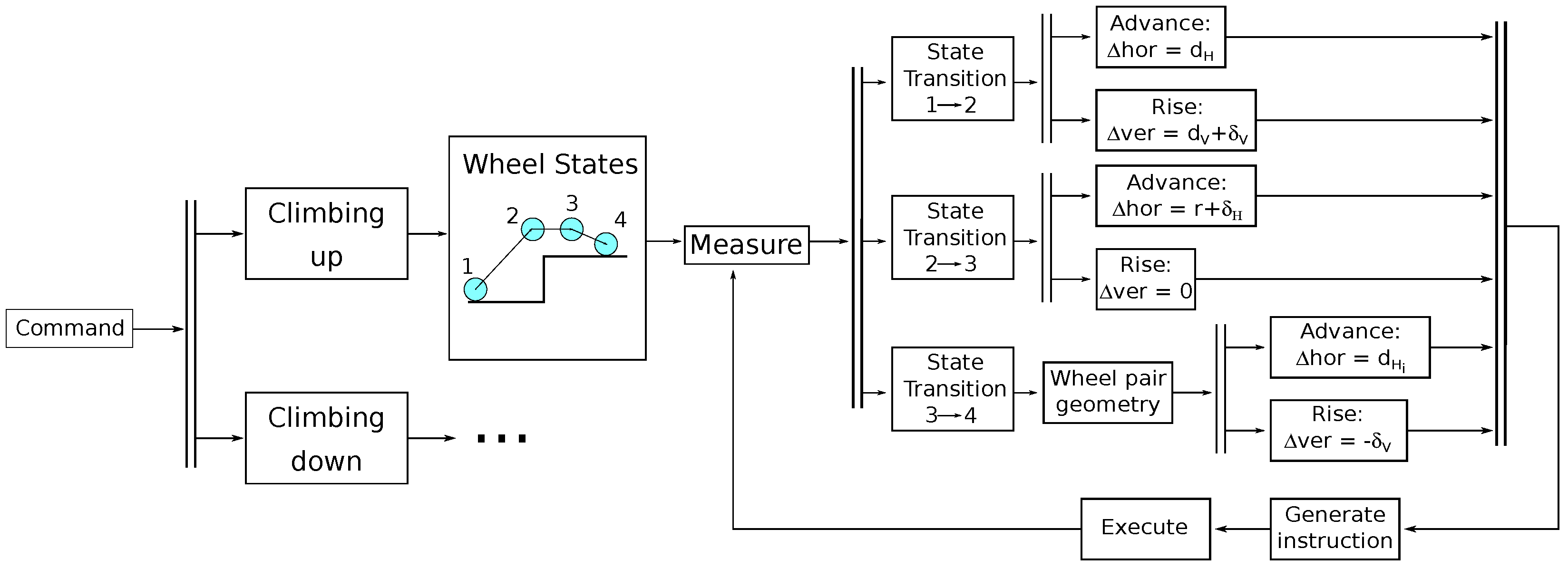
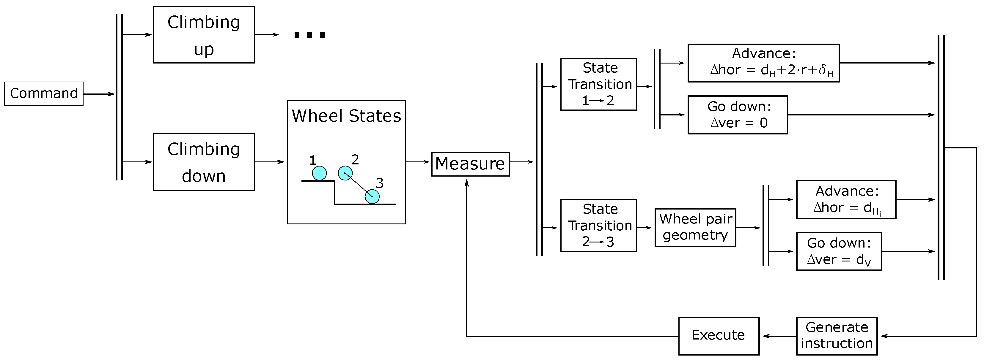
In this section, the strategy to control the actuators is presented. The objective is to explain how the coordinates of the wheels change in order to climb up or climb down a stair. Figure 3 and Figure 4 show the strategies followed when climbing up and down a stair, respectively. The trajectory of each wheel is calculated by defining intermediate points, which are denoted as wheel states. Four and three states are defined for climbing up and climbing down, respectively.
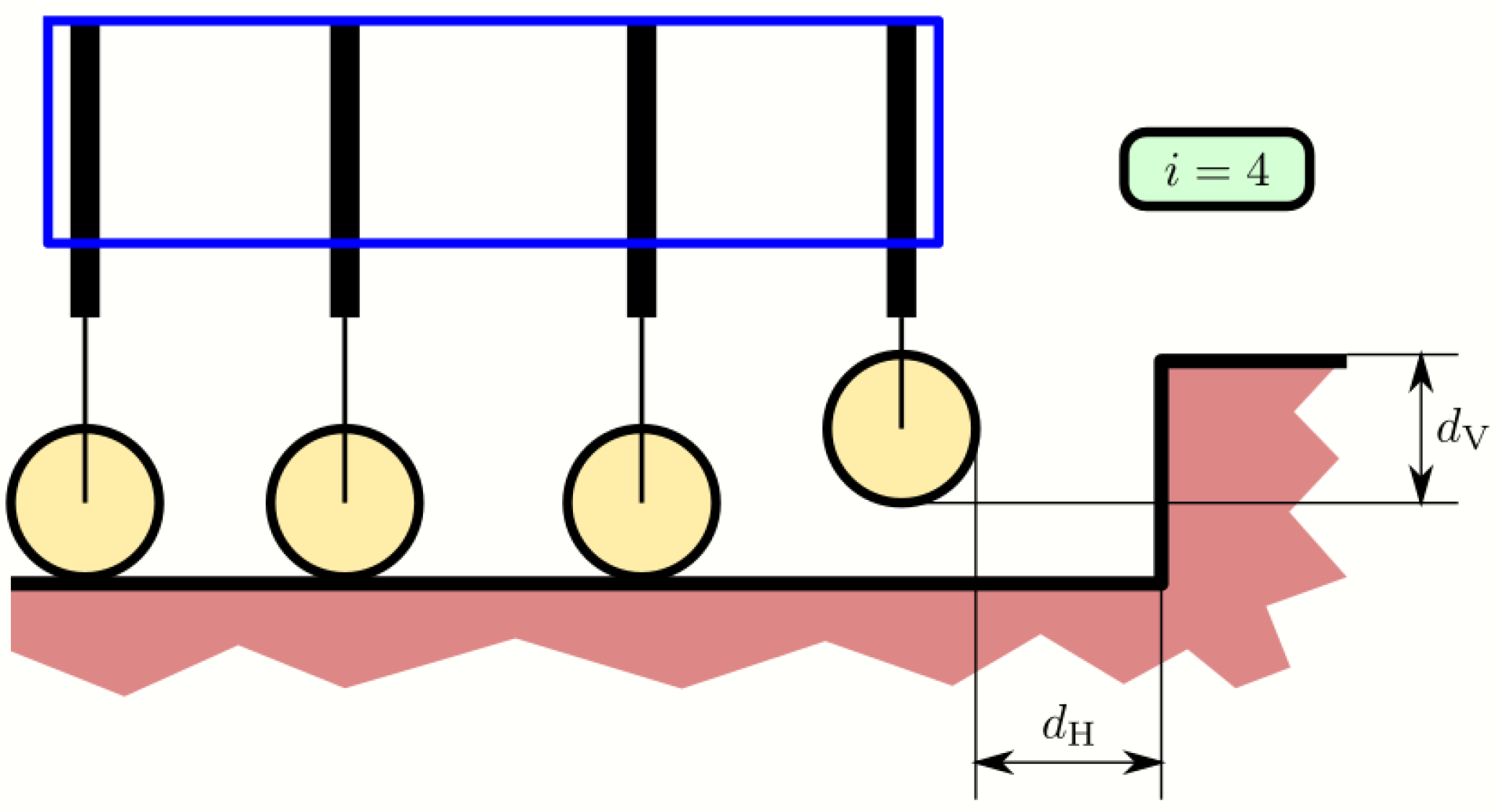
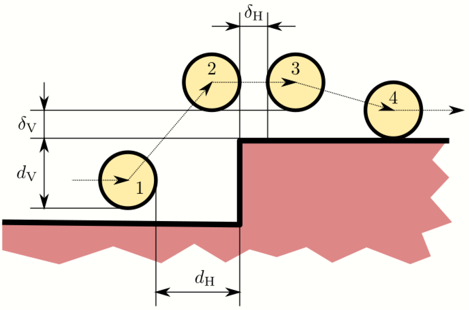
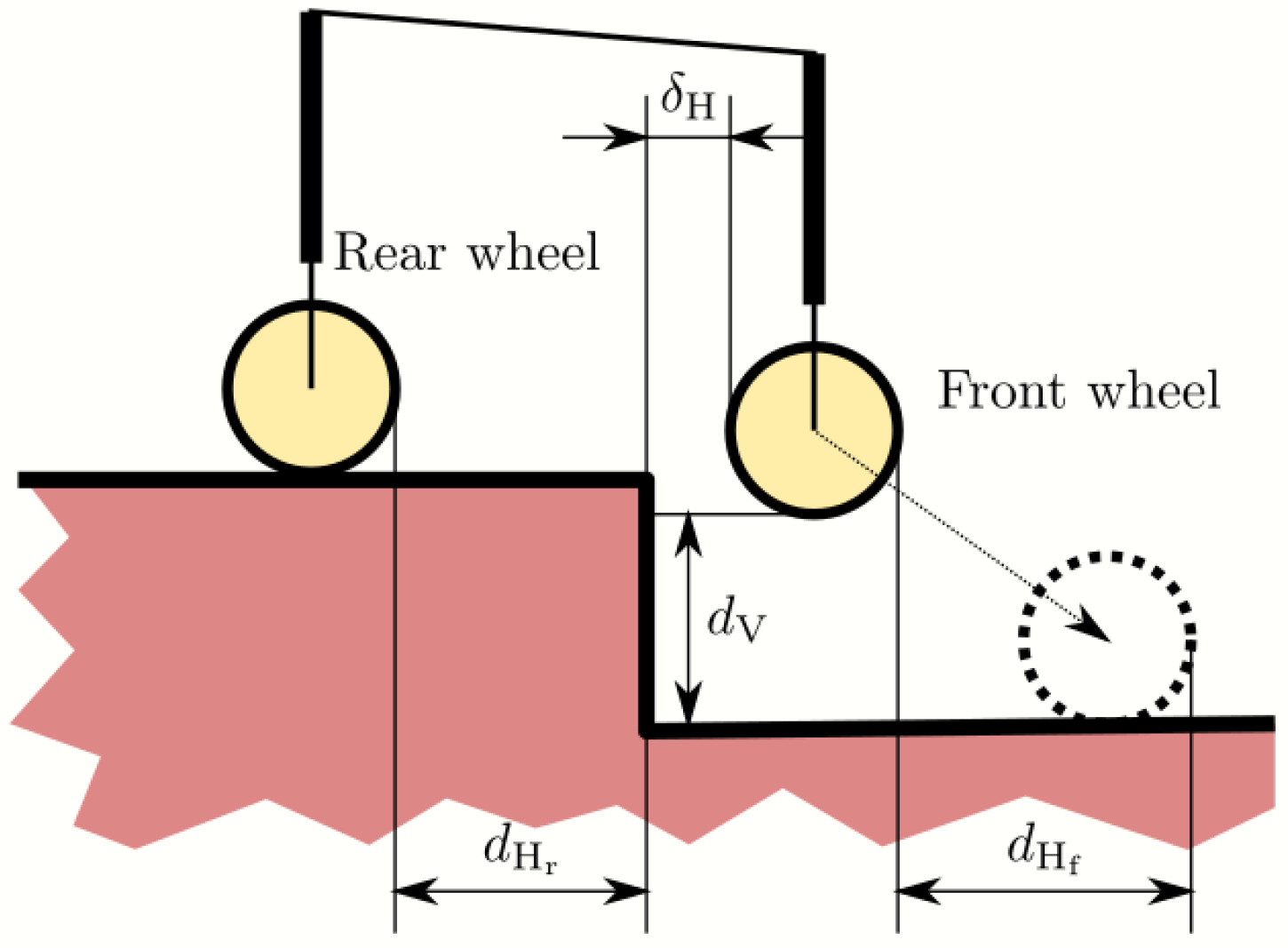
Then, the wheel that changes its height in each iteration is decided by the command M e a s u r e . M e a s u r e gets the index of the wheel that is closest to its nearest step (denoted i), providing the horizontal d H and the vertical d V distances (see Figure 5).
The commands A d v a n c e , R i s e and G o D o w n are used to move the wheels through the state transitions. Note that A d v a n c e / R i s e and A d v a n c e / G o D o w n are executed in parallel to save time. A d v a n c e is achieved with the motors of wheels 1 and 2. R i s e and G o D o w n can be achieved with the linear actuators defined in Equation (4).
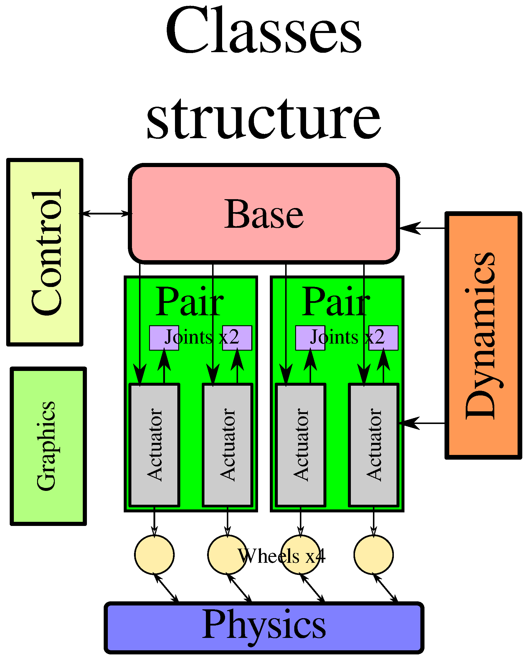
Figure 6 shows the software architecture of the control software. The first level is W h e e l s x 4 , which corresponds to the wheel level. Each wheel is controlled considering the equations described in Section 2. The second level is P a i r , where the front and back pair are separated. The first pair controls the actuators of wheels 4 and 3 ( L 4 and L 3 ), and the second pair the wheels 2 and 1 ( L 2 and L 1 ). The third level is B a s e (i.e., wheelchair level), which coordinates the horizontal movement with the vertical movement. This level considers the kinematics equations and restrictions described in Section 2 and the control strategy. In addition, the procedure to change the vertical position of any wheel is also decided at this level. Note that the height of each wheel depends on the reference wheel (i.e., L 1 ), the length of its actuator and the angle β (i.e., L 9 ). The commands R i s e and G o D o w n consider the three levels mentioned above to change the height of each wheel.
The previous control architecture, which was published in [18], did not consider any acceleration/deceleration restrictions. However, the modification of the control architecture proposed in this work does consider these restrictions in all the actuators. In addition, different values of acceleration and velocity can be set. The low-level control considers the following restrictions:
  • a c t u a t o r u p : Speed for an actuator when it is elevating the wheel.
  • a c t u a t o r d w : Speed for an actuator when it is taking the wheel down.
  • e l e v a t e u p : Speed when the actuators are elevating the structure.
  • e l e v a t e d w : Speed when the actuators are taking the structure down.
  • i n c l i n e u p : Speed when the actuators are inclining the structure up.
  • i n c l i n e d w : Speed when the actuators are inclining the structure down.
  • s p e e d : Maximum horizontal speed.
  • a c c e l e r a t i o n : Maximum horizontal acceleration.
  • d e c e l e r a t i o n : Maximum horizontal deceleration.
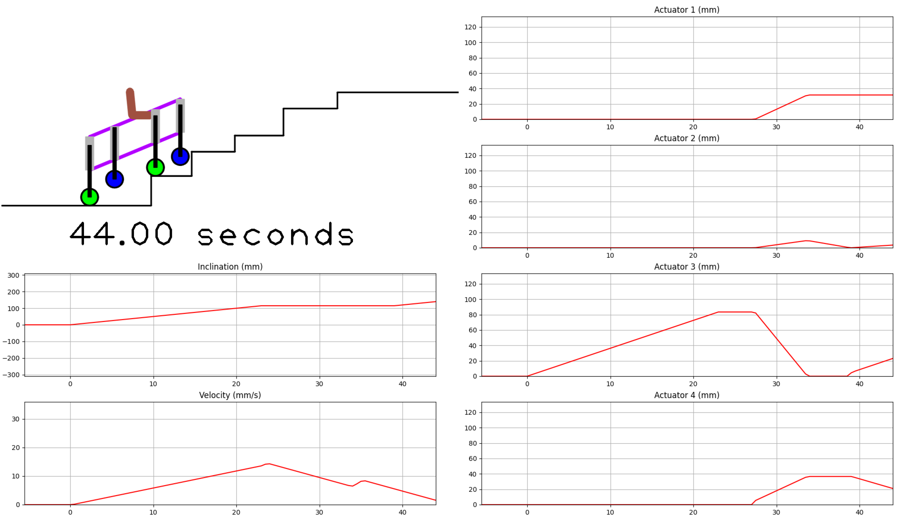
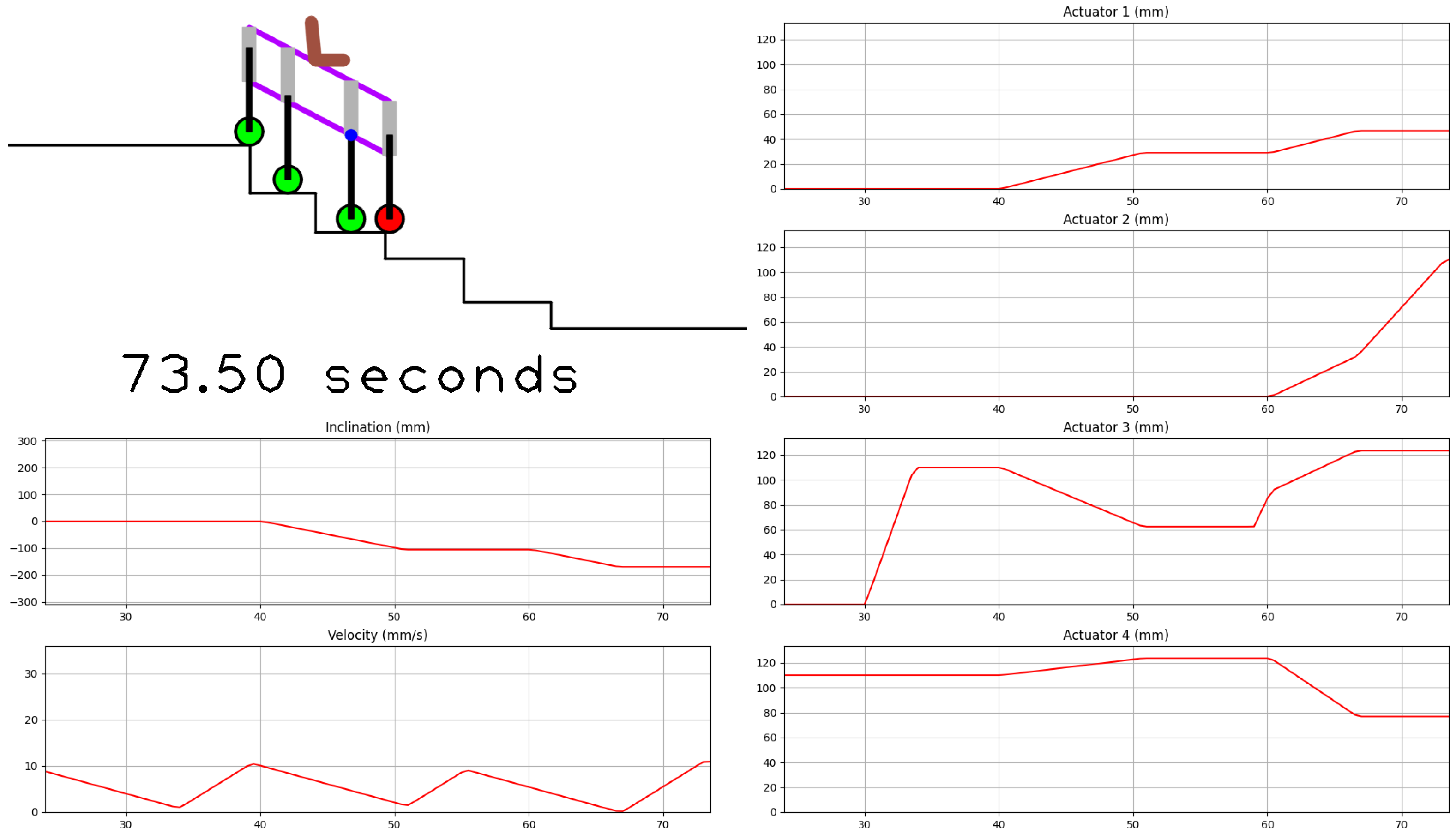
The computation of the horizontal velocity profiles (i.e., the low control level) is described in the following Technical Report ( https://github.com/pedrogil1919/Structure/blob/master/Structure/docs/dynamics/calculus.odt, accessed on 20 September 2022). The link (https://youtube.com/playlist?list=PL-cQTqyWA2d1upFVvzsNcJ0bn3QE4KyfV, accessed on 20 September 2022) includes some videos to show the trajectory generation when the wheelchair climbs a stair with several steps. Figure 7 and Figure 8 show two snapshots of these videos, corresponding to times equal to 44 and 73.5 s, respectively. These figures show: (i) current structure position (top-left), (ii) structure inclination (mm), measured as the difference in height between the front and the rear extremes of the structure, and horizontal velocity of the wheelchair (mm/s) (bottom-left) and (iii) actuator position ( L 1 , L 2 , L 3 and L 4 ) (mm) (right). It can be seen that the trajectories of Figure 7 and Figure 8 are smoother than Figures 13 and 14 of [18]. Therefore, the ergonomics of this new version of the control architecture have been improved.
In the following subsections, the three levels are explained in detail.

3.1. Individual Wheel Level

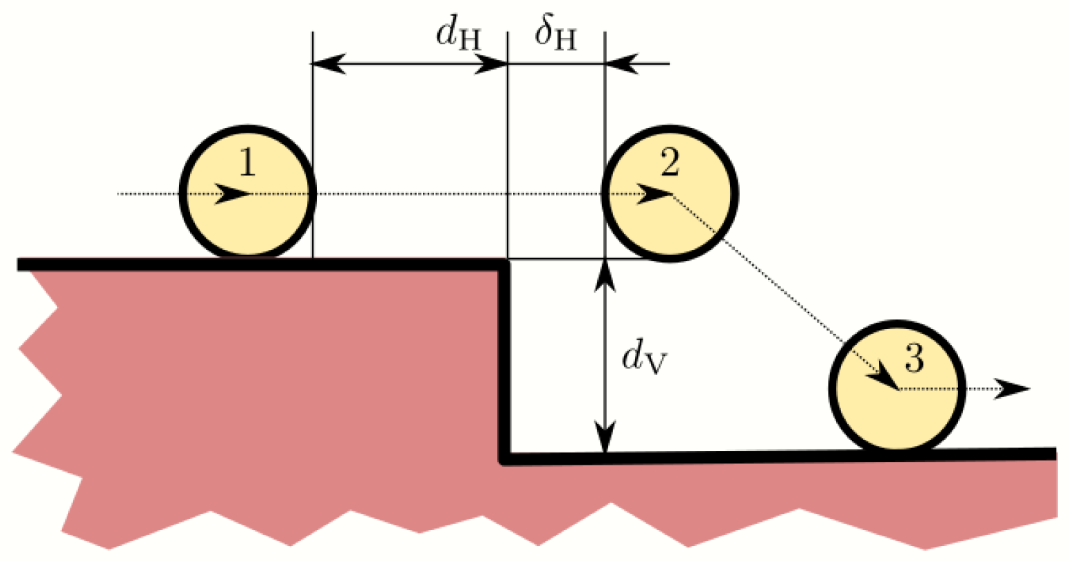
The climb up (see Figure 9) and climb down (see Figure 10) trajectories of an individual wheel are described herein. Both trajectories are divided in the states defined above, which are explained in detail in this subsection. The nomenclature is: (i) Δ x i and Δ y i are the horizontal and vertical displacements of the wheel i in each instruction, (ii) r is the radius of the wheel and (ii) δ H and δ V are additional displacements included to prevent wheel collisions with the stair, mainly due to sensor precision and geometric tolerances.

3.1.1. Climb Up—Figure 9

  • State 1. The command M e a s u r e obtains the distance d H and d V of the closest wheel (i).
  • State 2. Δ x = d H i and Δ y i = d V + δ V .
  • State 3. Δ x = r + δ H and Δ y i = 0 .
  • State 4. Δ y i = δ V . The horizontal position Δ x can be increased if possible since this strategy reduces the trajectory time. The value of Δ x depends on the wheel pair and wheelchair level.

3.1.2. Climb Down—Figure 10

  • State 1. The command M e a s u r e obtains the distance d H and d V of the closest wheel (i).
  • State 2. Δ x = d H i + δ H + 2 r and Δ y i = 0 .
  • State 3. Δ y i = d V . The horizontal position Δ x can be increased if possible since this strategy reduces the trajectory time.
Note that the rest of the wheels move accordingly without the risk of collision with any obstacle, since they are further from any obstacle than wheel i, as described above.

3.2. Wheel Pair Level

This subsection explains the wheel pair geometry considerations shown in Figure 3 (state transition from 3 to 4) and Figure 4 (state transition from 2 to 3). Note that the wheelchair in Figure 1 can be considered as two independent wheel pairs. Thus, the first wheel (4 or 2) climbs up (or climbs down) the step first. This subsection denotes the first and second wheels of the pairs as f (front) and r (rear), respectively. The objective is to decide the maximum value of d H f in the last A d v a n c e instruction, which depends on d H r .
Figure 11 and Figure 12 show the distances d H f and d H r in state 3 (climb up) and state 2 (climb down), respectively. In both cases, it must be guaranteed that d H f < d H r . Therefore, the maximum velocity for the last command A d v a n c e is limited by this restriction.
Wheel pair-level also checks that, at any time, at least one wheel of each pair is on the ground to ensure wheelchair stability. Note that when wheels 1 and 4 are in the air, and the wheelchair is supported only on wheels 2 and 3, the wheelchair is in the state of least stability. This problem will be addressed later.

3.3. Wheelchair Level

This level coordinates both wheel pairs, computing the horizontal velocity of the structure in order to ensure that there is no collision between wheels and obstacles. In addition, this level coordinates the length of the actuators L 1 , L 2 , L 3 , L 4 and L 9 in the R i s e and G o D o w n commands. This coordination depends on the wheel that is currently changing its height. That is, if when trying to shift an actuator, there is not enough space for the actuator to complete the motion, the structure must be elevated/inclined to gain more space. Thus, this movement is implemented as follows:
  • Wheels 4 and 1: The space is gained by changing β , i.e., inclining the structure. Then, if there is still not enough room for the actuator to achieve the height required, the wheelchair is elevated until the actuator can achieve it.
  • Wheels 2 and 3: As opposed to wheels 4 and 1, first elevate the wheelchair. If the total height can not be achieved, the structure is inclined (change β ) until the actuator can achieve it.
Note that on some occasions, the whole height can not be achieved, due to, for instance, to a too high stair step. In this case, the instruction can not be completed, and so, the stair can not be climbed, requiring a redesign of the structure dimensions.

4. Optimization

The optimization is carried out as follows:
  • Stair definition. The number of steps to climb up and climb down and the variables R H and T S are defined.
  • Actuator dynamic restrictions. The following variables are defined: a c t u a t o r u p , a c t u a t o r d w , e l e v a t e u p , e l e v a t e d w , i n c l i n e u p , i n c l i n e d w , s p e e d , a c c e l e r a t i o n and d e c e l e r a t i o n .
  • Wheelchair constant parameters. The following variables are defined: wheel ratios ( r 1 , r 2 , r 3 and r 4 ), sensor errors ( δ H , δ V ), maximum value of inclination ( β ), wheelchair length ( L H ) and minimum values for a, b and c.
  • Calculate the maximum values for parameters a and c from Equation (5) and the variables defined above.
  • Define the resolution for the intervals of a and c.
  • Calculate the total time used to climb up and down the stair defined above for each possible pair values of a and c.
  • Plot the total time as a function of a and c.
  • Decide the best configurations of a and c.
The optimization, control architecture and leg-based stair-climbing mechanism have been programmed in Python. This program, which models a non-linear problem, can calculate the total time used to climb up and down a defined stair in a few seconds. All the code can be downloaded from the following public repository, (https://github.com/pedrogil1919/Structure, accessed on 20 September 2022).

Application Example

The objective of this application example is to show that the configuration of the parameters a, b and c is not obvious. The application example considers the following configuration:
  • Stair definition: Number of steps to climb up and climb down equal to 5 steps, R H = 175 mm and T S = 280 mm.
  • Wheels radius: r 1 = r 2 = r 3 = r 4 = 60 mm
  • Actuator dynamic restrictions:
    a c t u a t o r u p = 20 mm/s
    a c t u a t o r d w = 30 mm/s
    e l e v a t e u p = 5 mm/s
    e l e v a t e d w = 10 mm/s
    i n c l i n e u p = 4 mm/s
    i n c l i n e d w = 8 mm/s
    s p e e d = 30 mm/s
    a c c e l e r a t i o n = 0.8 mm/s 2
    d e c e l e r a t i o n = 1.8 mm/s 2
  • Wheelchair constant parameters (see Table 1):
  • The resolution grid for parameters a and c for the brute-force search chosen is equal to 1 mm.
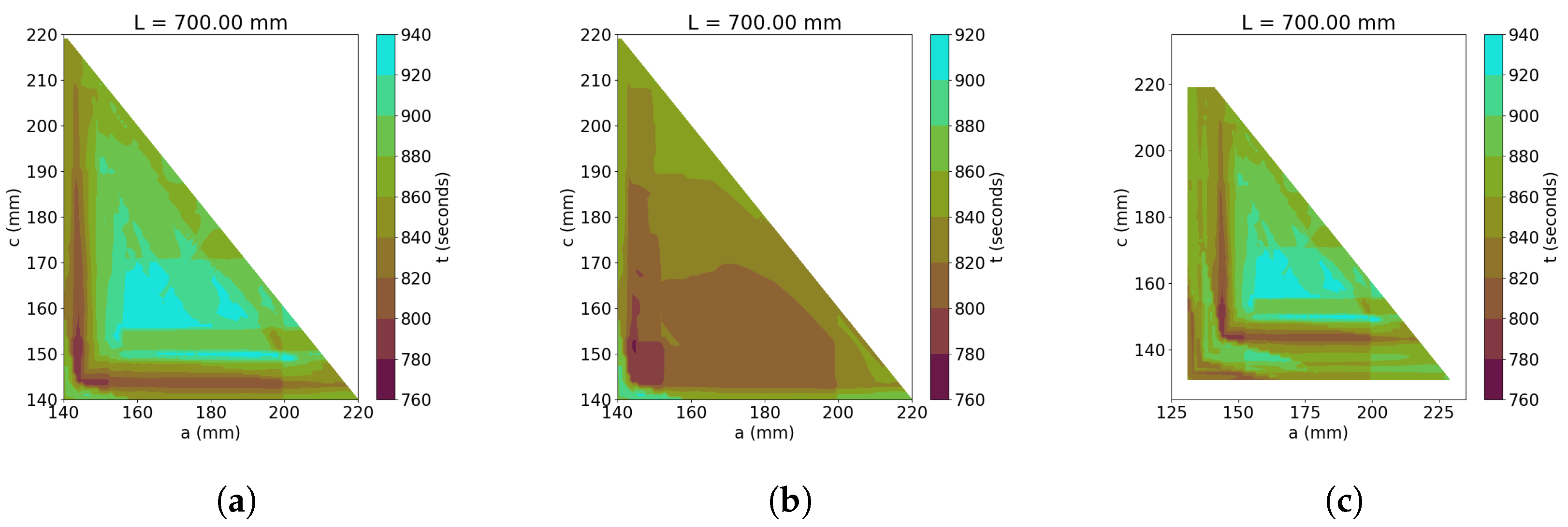
The first set of figures (Figure 13) plots the total time required to climb up and down the stair as a function of parameters a (horizontal axis) and c (vertical axis), considering a wheelchair with L H = 700 mm, minimum value for a = c = 140 mm, minimum value for b = 340 mm, actuators length L 1 L 4 = 250 mm and two intervals of β . Note that the maximum value for a is reached when b and c are minimum and vice versa. In the following figures, the position for ( a , c ) painted in white is a configuration where the system can not give a valid result. This can be a forbidden dimension, according to the restrictions defined above (top-right triangle), or a wheelchair configuration where the control algorithm can not find a valid trajectory to climb up or down the stair (white dots inside the bottom-left triangle).
Figure 13a shows the results when the minimum value of a = c = 140 mm and there is no limitation in the angle β . The minimum time is around 760 s and the best configurations are achieved with a around 143–152 mm and c around 143–160 mm. In addition, note that points close to the main diagonal of the colormap graph correspond with the smallest values for b (distance between wheels 2 and 3), but we know that the larger this value, the more stable the wheelchair is when wheels 1 and 4 are in the air, and the wheelchair is supported on wheels 2 and 3. Therefore, the objective is to find points as close to the bottom-left corner of the graph as possible. Thus, we conclude that it is better to consider a and c around 143 mm.
Figure 13b limits the minimum absolute value of the angle β to π / 4 and keeps the same configuration as in Figure 13a. Figure 13b shows that, for the considered control architecture, it is better to limit this angle. The reason is that there are more values of a and c where a lower total time is achieved than in Figure 13a. Figure 13b shows that the best values of a and c are around 143–152 mm, which is also convenient for increasing the stability of the wheelchair when wheels 2 and 3 support the structure.
Figure 13c shows the influence of the minimum distance between wheels 1 and 2 and between wheels 3 and 4. The minimum value of a and c is now considered equal to 125 mm. The main effect of this reduction is that there are more configurations where the control architecture can climb up and climb down the stairs. However, the optimal configurations are identical to Figure 13a.
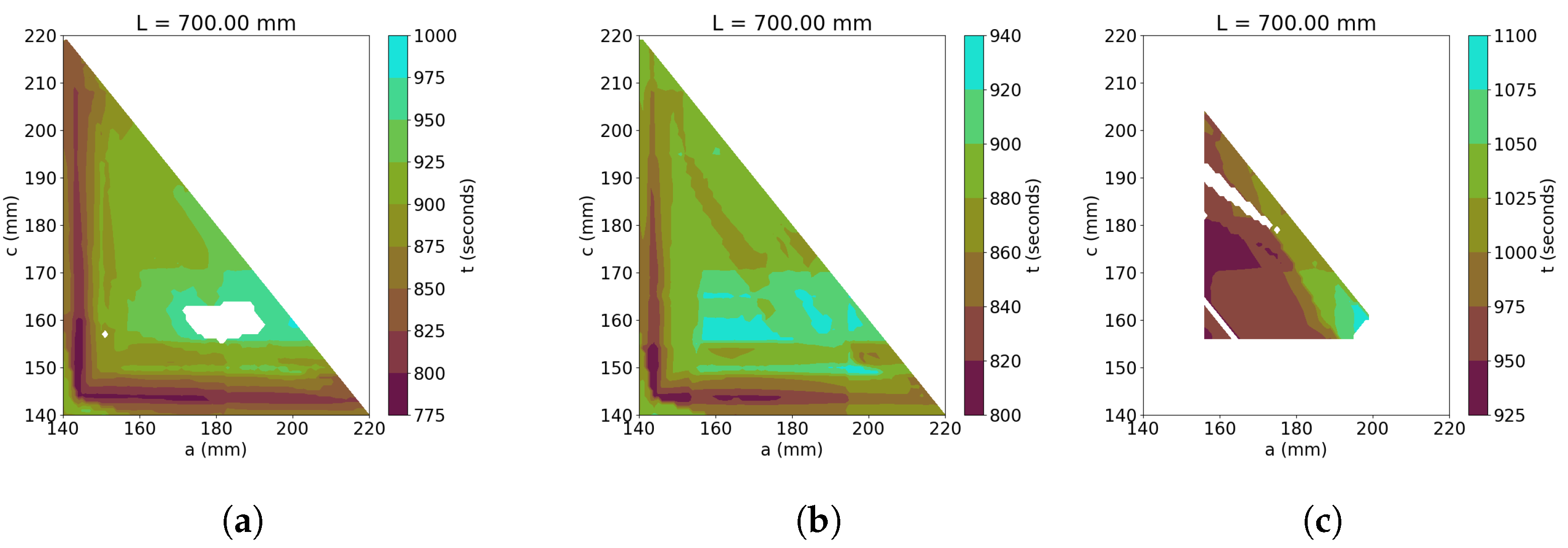
The second set of figures (Figure 14) is plotted by considering three different values of L H when there is no limitation on angle β . The rest of the configuration is L H = 700 mm, minimum values of b = 340 mm and a = c = 140 mm, which are the same as in Figure 13a with different values of L 1 L 4 . Figure 14a considers the actuator lengths equal to R H + δ V . Thus, the wheelchair can climb up or climb down one defined step without changing angle β . Figure 14b considers the actuator lengths equal to 2 R H + 2 δ V . Thus, the wheelchair can climb up or climb down two steps without changing angle β . If Figure 13a and Figure 14a,b are compared, it can be noted that the best configurations are with a and c of around 143 mm. In addition, the total time in Figure 14a,b is larger than in Figure 13a. Then, if the cost of the actuators is not considered, the best configuration when L H = 700 mm is with L 1 L 4 = 250 mm. Finally, we have included one more figure to show the influence of L 1 L 4 in the total time. In Figure 14c, we test the system for an actuator length smaller than R H , more specifically, equal to 136 mm. Although total times are greater than in the previous examples, and the number of valid configurations is less, this example shows that the wheelchair can even climb stairs with a raiser height taller than its actuators.
Thus, the main conclusions of the last six figures are that angle β should be limited, so the length of actuator L 9 , and that the actuator lengths should be between the riser heights of one and two steps. Thus, the control architecture has found the best trade-off between the lengths of L 1 L 4 and the length of L 9 .
Finally, the last comparison is shown in Figure 15. Figure 15a–c shows the influence of L H when it is considered on a wheelchair with L 1 L 4 = 250 mm, minimum values of a = c = 140 mm, maximum values of a = c = 220 mm and no limitation in β . These figures can be compared with Figure 13a. The objective is to show the influence of L H on the total time. The increment of L H , keeping the minimum and maximum values of a and c, can obtain configurations with bigger values of b, which are more stable. The first conclusion is that if L H is increased, the total time is also increased. The second conclusion is that there are more local areas where a minimum total time can be achieved. This can be better observed in Figure 15b when L H = 900 mm. If L H = 750 mm, there are two areas. The first one is with a or c equal to the minimum (140 mm). Thus, the best configuration must be a = c = 140 mm ( b = 470 mm). The other area is with a around 190 mm and with c around 150 mm. However, this configuration is less stable. If the criterium of stability is considered, the best configurations for L H = 900 mm (Figure 15b) are with a around 140 mm and c around 175 mm ( b = 585 mm). The configuration with a around 175 mm and c around 155 mm can also be considered ( b = 570 mm). Finally, Figure 15c has two local areas. The first one is with a around 205 mm and with c around 140 mm ( b = 655 mm). The second area is with a around 180 mm and with c around 150 mm ( b = 670 mm). Therefore, if L H is increased, the stability of the mechanism is better, but the total time is also increased.
The nine optimization examples carried out in this section show that the optimal wheelchair should have: (i) actuator lengths of around 250 mm, which is a value between R H + δ V and 2 R H + δ V , (ii) there are local minima close to the minimum values of a and c, which motivate the optimization of the mechanism, (iii) variable L H does not significantly affect the total time and increases the stability of the wheelchair and (iv) limitation of the angle β simplifies the optimization. Thus, the wheelchair proposed in Figure 13b is the best, with a = c = 145 mm.

5. Conclusions

In this work, we have shown that the optimal configuration of the leg-based stair-climbing wheelchair is not obvious. Although we only considered the sum of the total time to climb up and the total time to climb down the same stair, parameters a and c depend on the minimum distances between wheels, the angle β , the sensor errors ( δ V and δ H ) and the total length of the mechanism ( L H ). The main conclusions are:
  • Angle β and actuator lengths L 1 L 4 should be limited. Thus the control architecture can better find an optimal trajectory, reducing the total time. In addition, the reduction in L 1 L 4 makes the mechanism more competitive from an economical point of view.
  • The sensor errors affect the range of parameters of a and c that can climb up and climb down the stairs, but the total time is not significantly affected. Therefore, the control architecture can include these uncertainties.
  • The length of the mechanism ( L H ) increases its stability and the total time is not significantly increased.
The control architecture and optimization must be considered in the future in a multi-objective optimization with all the parameters defined in this work. Thus, the optimization should consider: the total time, the stability of the mechanism and the energy needed by the actuators. In addition, the experimental validation of the optimized prototype will be considered in future work.

Author Contributions

Conceptualization, E.P. and P.G.-J.; methodology, E.P. and P.G.-J.; software, D.D.-M. and P.G.-J.; validation, D.D.-M., E.P. and P.G.-J.; formal analysis, E.P. and P.G.-J.; investigation, E.P., S.M.-B. and P.G.-J.; resources, E.P., C.A.-C., S.M.-B. and P.G.-J.; data curation, E.P. and P.G.-J.; writing—original draft preparation, D.D.-M., E.P. and P.G.-J.; supervision, P.G.-J.; project administration, P.G.-J.; funding acquisition, P.G.-J. All authors have read and agreed to the published version of the manuscript.

Funding

This work has been supported by the following research projects: CM/JIN/2019-022 of CAM-UAH and PID2019-104323RB-C31 of Spain’s Ministry of Science and Innovation.

Institutional Review Board Statement

Not applicable.

Informed Consent Statement

Not applicable.

Data Availability Statement

Not applicable.

Conflicts of Interest

The authors declare no conflict of interest.

References

  1. Tao, W.; Xu, J.; Liu, T. Electric-powered wheelchair with stair-climbing ability. Int. J. Adv. Robot. Syst. 2008, 14, 1–13. [Google Scholar] [CrossRef]
  2. Wheelchair88 Limited. PW-4x4Q Stair Climbing Wheelchair, All Terrain 4 Wheel Drive Power Chair. 2017. Available online: https://www.wheelchair88.com/product/pw-4x4q/ (accessed on 2 August 2022).
  3. Yuan, J.; Hirose, S. Research on leg-wheel hybrid stair-climbing robot, Zero Carrier. In Proceedings of the IEEE International Conference on Robotics and Biomimetics, Shenyang, China, 22–26 August 2004; pp. 654–659. [Google Scholar]
  4. Ikeda, H.; Toyama, T.; Maki, D.; Sato, K.; Nakano, E. Cooperative step-climbing strategy using an autonomous wheelchair and a robot. Robot. Auton. Syst. 2021, 135, 103670. [Google Scholar] [CrossRef]
  5. Heinrich, A. Topchair-S Wheelchair Has No Problem with Stairs, New Atlas. 2016. Available online: https://newatlas.com/topchairs-stair-climbing-wheelchair/41421/ (accessed on 2 August 2022).
  6. Quaglia, G.; Nisi, M. Design of a self-leveling cam mechanism for a stair climbing wheelchair. Mech. Mach. Theory 2017, 112, 84–104. [Google Scholar] [CrossRef]
  7. Quaglia, G.; Franco, W.; Oderio, R. Wheelchar.q, a motorized wheelchair with stair climbing ability. Mech. Mach. Theory 2011, 46, 1601–1609. [Google Scholar]
  8. Giuseppe, Q.; Walter, F.; Matteo, N. Stair-Climbing Wheelchair.q05: From the Concept to the Prototype. In Advances in Service and Industrial Robotics: Proceedings of the 27th International Conference on Robotics in Alpe-Adria Danube Region (RAAD 2018), Patras, Greece, 6–8 June 2018; Aspragathos, N., Koustoumpardis, P., Moulianitis, V., Eds.; Springer: Cham, Switzerland, 2018; Volume 67. [Google Scholar]
  9. Morales, R.; Feliu, V.; González, A.; Pintado, P. Kinematic model of a new staircase climbing wheelchair and its experimental validation. Int. J. Robot. Res. 2006, 25, 825–841. [Google Scholar] [CrossRef]
  10. Gonzalez, A.; Ottaviano, E.; Ceccarelli, M. On the kinematic functionality of a four-bar based mechanism for guiding wheels in climbing steps and obstacles. Mech. Mach. Theory 2009, 44, 1507–1523. [Google Scholar] [CrossRef]
  11. Morales, R.; Chocoteco, J.; Feliu, V.; Sira-Ramirez, H. Obstacle surpassing and posture control of a stairclimbing robotic mechanism. Control. Eng. Pract. 2013, 21, 604–621. [Google Scholar] [CrossRef]
  12. Chocoteco, J.; Morales, R.; Feliu, V.; Sánchez, L. Trajectory Planning for a Stair-Climbing Mobility System Using Laser Distance Sensors. IEEE Syst. J. 2016, 10, 944–956. [Google Scholar] [CrossRef]
  13. Chocoteco, J.A.; Morales, R.; Feliu-Batlle, V. Enhancing the Trajectory Generation of a Stair-Climbing Mobility System. Sensors 2017, 11, 2608. [Google Scholar] [CrossRef] [Green Version]
  14. Sugahara, Y.; Hashimoto, K.; Kawase, M.; Ohta, A.; Sunazuka, H.; Tanaka, C.; Lim, H.; Takanishi, A. Walking pattern generation of a biped walking vehicle using a dynamic human model. In Proceedings of the IEEE/RSJ International Conference on Intelligent Robots and Systems, Beijing, China, 9–15 October 2006; pp. 2497–2502. [Google Scholar]
  15. Wang, H.; He, L.; Li, Q.; Zhang, W.; Zhang, D.; Xu, P. Research on Kind of Leg-Wheel Stair-Climbing Wheelchair. In Proceedings of the IEEE International Conference on Mechatronics and Automation, Tianjin, China, 3–6 August 2014; pp. 2101–2105. [Google Scholar]
  16. Pereira, E.; Gómez-Moreno, H.; Alén-Cordero, C.; Gil-Jiménez, P.; Maldonado-Bascón, M. A Novel Approach for a Leg-based Stair-climbing Wheelchair based on Electrical Linear Actuators. In Proceedings of the 16th International Conference on Informatics in Control, Automation and Robotics, Prague, Czech Republic, 29–31 July 2019. [Google Scholar]
  17. Kluth, H. Stair Climbing Wheelchair. U.S. Patent US4569409A, 7 July 1982. [Google Scholar]
  18. Delgado-Mena, D.; Pereira, E.; Alén-Cordero, C.; Maldonado-Bascón, S.; Gil-Jiménez, P. Control architecture for a novel Leg-Based Stair-Climbing Wheelchair. In Proceedings of the European Conference on Mobile Robots (ECMR), Bonn, Germany, 31 August–3 September 2021; pp. 1–6. [Google Scholar]
  19. Fomento. Documento Básico SUA, Seguridad de Utilización y Accesibilidad, Ministerio de Fomento Secretaría de Estado de Infraestructuras, Transporte y Vivienda Dirección General de Arquitectura, Vivienda y Suelo, 2010.
Figure 1. Working principle. It can be seen that the user is always kept horizontal when the wheelchair is horizontal, is climbing up or climbing down an obstacle.
Actuators 11 00289 g001
Figure 2. Wheelchair restrictions when the mechanism climbs up and climbs down.
Actuators 11 00289 g002
Figure 3. Strategy followed in order to climb up [18].
Actuators 11 00289 g003
Figure 4. Strategy followed in order to climb down [18].
Actuators 11 00289 g004
Figure 5. Practical example of command M e a s u r e , where the closest wheel is i = 4 [18].
Actuators 11 00289 g005
Figure 6. Software structure of the control architecture [18].
Actuators 11 00289 g006
Figure 7. Data previously generated before 44.00 s of the trajectory generator for a stair with diferent step sizes (positive H R ).
Actuators 11 00289 g007
Figure 8. Data previously generated before 73.5 s of the trajectory generator for a stair with diferent step sizes (negative H R ).
Actuators 11 00289 g008
Figure 9. Individual Wheel level - climb up [18].
Actuators 11 00289 g009
Figure 10. Individual Wheel level—climb down [18].
Actuators 11 00289 g010
Figure 11. Wheel pair level—climb up.
Actuators 11 00289 g011
Figure 12. Wheel pair level—climb down.
Actuators 11 00289 g012
Figure 13. Wheelchair with L H = 700 mm, minimum value of b = 270 mm and L 1 L 4 = 250 mm. Influence of a m i n , c m i n and β in total time. (a) a m i n = c m i n = 140 mm and | β | ( π / 2 , 0 ) , (b) a m i n = c m i n = 140 mm and | β | [ p i / 4 , p i / 2 ) , (c) a m i n = c m i n = 125 mm and | β | ( π / 2 , 0 ) .
Actuators 11 00289 g013
Figure 14. Wheelchair with L H = 700 mm, minimum values of b = 270 mm and a = c = 140 mm. Influence of actuator lengths on total time. (a) Length of actuators L 1 L 4 = 185 mm, (b) Length of actuators L 1 L 4 = 355 mm, (c) Length of actuators L 1 L 4 = 136 mm.
Actuators 11 00289 g014
Figure 15. Wheelchair length of actuators L 1 L 4 = 250 mm, minimum values of a = c = 140 mm and | β | [ 0 , 90 ] . Influence of L H on total time. (a) L H = 750 mm and minimum value of b = 320 mm, (b) L H = 900 mm and minimum value of b = 470 mm, (c) L H = 1000 mm and minimum value of b = 570 mm.
Actuators 11 00289 g015
Table 1. Optimization parameters.
Figure L H a min = c min b min a max = c max β L 1 L 4
Figure 13a700 mm140 mm340 mm220 mm ( π / 2 , 0 ) 250 mm
Figure 13b700 mm140 mm340 mm220 mm [ π / 4 , π / 2 ) 250 mm
Figure 13c700 mm125 mm340 mm235 mm ( π / 2 , 0 ) 250 mm
Figure 14a700 mm140 mm340 mm220 mm ( π / 2 , 0 ) 185 mm
Figure 14b700 mm140 mm340 mm220 mm ( π / 2 , 0 ) 355 mm
Figure 14c700 mm140 mm340 mm220 mm ( π / 2 , 0 ) 136 mm
Figure 15a750 mm140 mm390 mm220 mm ( π / 2 , 0 ) 250 mm
Figure 15b900 mm140 mm540 mm220 mm ( π / 2 , 0 ) 250 mm
Figure 15c1000 mm140 mm640 mm220 mm ( π / 2 , 0 ) 250 mm
Publisher’s Note: MDPI stays neutral with regard to jurisdictional claims in published maps and institutional affiliations.