Article

Estimation of the Dynamic Parameters of the Bearings in a Flexible Rotor System Utilizing Electromagnetic Excitation by a Built-In Motor

1
Key Laboratory of Education Ministry for Modern Design & Rotor-Bearing System, Theory of Lubrication and Bearing Research Institute, Xi’an Jiaotong University, Xi’an 710049, China
2
Institute of Innovative Research, Tokyo Institute of Technology, 4259 Nagatsuta-cho, Midori-ku, Yokohama 226-8503, Japan
*
Author to whom correspondence should be addressed.
Actuators 2022, 11(1), 1; https://doi.org/10.3390/act11010001
Submission received: 10 November 2021 / Revised: 14 December 2021 / Accepted: 21 December 2021 / Published: 23 December 2021
(This article belongs to the Section Control Systems)

Abstract

:
Estimation of the dynamic parameters of bearings is essential in order to be able to interpret the performance of rotating machinery. In this paper, we propose a method to estimate the dynamic parameters of the bearings in a flexible rotor system. By utilizing the electromagnetic excitation generated by a built-in PM motor and finite element (FE) modeling of the rotor, safe, low-cost, and real-time monitoring of the bearing dynamics can be achieved. The radial excitation force is generated by injecting an alternating d-axis current into the motor windings. The FE model of the rotor and the measured frequency responses at the motor and bearing locations are used to estimate the dynamic parameters of the bearings. To evaluate the feasibility of the proposed method, numerical simulation and experiments were carried out on a flexible rotor system combined with a bearingless motor (BELM) having both motor windings and suspension windings. The numerical simulation results show that the proposed algorithm can accurately estimate the dynamic parameters of the bearings. In the experiment, the estimates made when utilizing the excitation force generated by the motor windings are compared with the estimates made when utilizing the excitation force generated by the suspension windings. The results show that most of the stiffness and damping coefficients for the two experiments are in good agreement, within a maximum error of 8.92%. The errors for some coefficients are large because the base values of these coefficients are small in our test rig, so these coefficients are sensitive to deviations. The natural frequencies calculated from the dynamic parameters estimated from the two experiments are also in good agreement, within a maximum relative error of 3.04%. The proposed method is effective and feasible for turbomachines directly connected to motors, which is highly significant for field tests.

1. Introduction

Rotating machinery with built-in motors, such as compressors and canned motor pumps, are widely used in the oil and gas industries. To achieve high stability and reliability for long-time operation, real-time monitoring during rotation is necessary. Oil-film bearings are essential for supporting a large rotor, and the dynamic parameters of the bearings have a significant effect on the dynamic characteristics of the rotor. The main dynamic parameters of oil-film bearings are the stiffness and damping parameters [1]; however, these parameters change over time because of wear, solid deposition, and poor lubrication conditions, making the parameters estimated by theoretical analysis different from the actual parameters in practical rotor systems. Therefore, it is necessary to measure the dynamic parameters of the bearings in real time in order to interpret the dynamic characteristics of the rotor system.
Many methods have been developed to measure the dynamic parameters of bearings in full-scale rotor systems [2,3]. In contrast to applying forces on the bearing pedestal [4] to measure these parameters, forces applied to the rotor shaft are suitable for full-scale rotor systems [5,6,7]. An impact hammer, an unbalanced mass, or some form of excitation can generate the force, and the corresponding acceleration, velocity, and displacement of the rotor can be used to estimate the dynamic parameters of the bearing. Using an impact hammer [8] requires the appropriate experience, and it is dangerous to hammer a rotating rotor. The unbalanced mass [9,10] method is simple and accurate; however, at least two test runs are required to estimate the eight bearing parameters, and the necessary shutdown and disassembly/reassembly of the rotor system takes a lot of time, leading to economic losses.
Dynamic forces generated by excitation in order to measure the dynamic parameters of bearings and for stability testing of the rotor system have been used for many years. Electromagnetic excitation [11,12,13] is more widely used because it can be applied in a noncontact manner. For example, using an active magnet bearing (AMB) [14,15,16] for electromagnetic excitation has been successfully applied in industry and laboratory tests. However, the use of electromagnetic excitation requires additional space and an extended shaft to install the excitation mechanism. The basic design of the rotor system needs to be changed, which increases the development and production costs. Therefore, a space-saving and low-cost method is required to measure the dynamic parameters without significantly changing the system design.
For a rotor system supported by oil-film bearings combined with a built-in PM motor, the eccentricity of the bearing journal and residual unbalance force in the rotor result in static and dynamic eccentricity in the motor. The eccentricity induces an unbalanced magnetic force (UMF) in the radial direction.
In our previous research [17,18], the UMF was utilized as a radial excitation force. Excitation forces at different frequencies were realized by injecting a sweep frequency d-axis current into the motor windings. Generally, injecting a constant d-axis current into the motor windings is performed in order to control the flux-weakening to enable rotation of the motor over a wide speed range, whereas we used an alternating d-axis current to change the bias magnetic flux to generate an alternating radial force. The UMF was used to measure the frequency response of the rotor system. The measured results were verified by comparing them with the frequency responses measured utilizing a radial magnetic bearing. Estimation of the dynamic parameters of bearings using the frequency responses measured utilizing UMF excitation has not been studied.
In this paper, we propose a method to estimate the dynamic parameters of oil-film bearings in a flexible rotor system utilizing electromagnetic excitation generated by a built-in PM motor. The dynamic parameters were estimated from measured frequency responses of the motor and the bearings and finite element (FE) modeling of the rotor.
Numerical simulation is used to explain and validate the proposed estimation algorithm. Experiments were carried out on a rotor supported by two oil-film bearings combined with a bearingless motor (BELM). Because the BELM functions as an independent PM motor and a radial magnetic bearing, radial excitation of the rotor by the PM motor and the radial magnetic bearing can be performed at the same rotor position. The proposed method was verified by comparing the results with the dynamic parameters estimated utilizing the measured frequency responses of the PM motor and the radial magnetic bearing of the BELM.
The remainder of this paper is organized as follows. In Section 2, we introduce the principle of the excitation force generated by the PM motor and describe the algorithm used to calculate the dynamic parameters of the bearings using the FE model of the rotor. In Section 3, the numerical simulation results are presented. The experimental setup and the estimated results are described in Section 4. Section 5 gives the conclusions.

2. Estimation Method

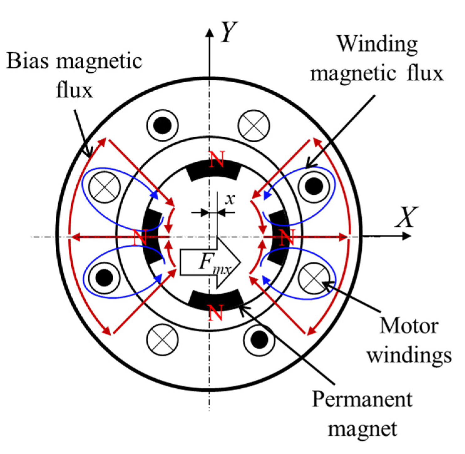
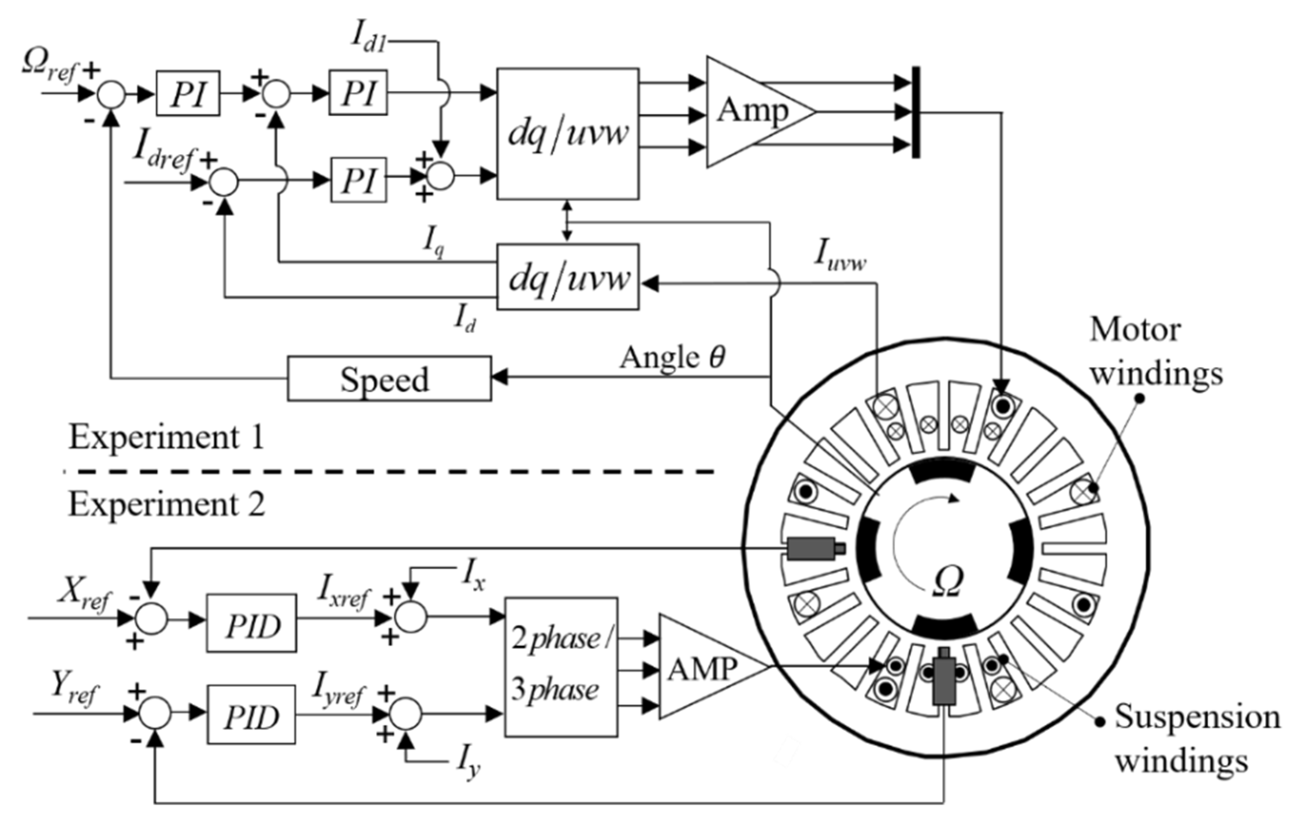
2.1. Excitation Force Generated by a PM Motor

Figure 1 shows a cross-sectional view of a PM motor with eccentricity in the X-direction. The red lines show the bias magnetic flux generated by the permanent magnets, and the blue lines show the magnetic flux generated by the motor windings.
In the motor, the magnetic fluxes in the air gaps in the positive and negative X-direction are strengthened and weakened by the eccentricity, respectively. The force generated in the X-direction can be expressed as [19]
F m x K s x + K d i d x
where Ks is the initial negative stiffness; Kd is the eccentricity–current–force coefficient; id is the d-axis current of the PM motor. Therefore, injecting an alternating d-axis current into the motor windings can generate a radial excitation force in the PM motor.

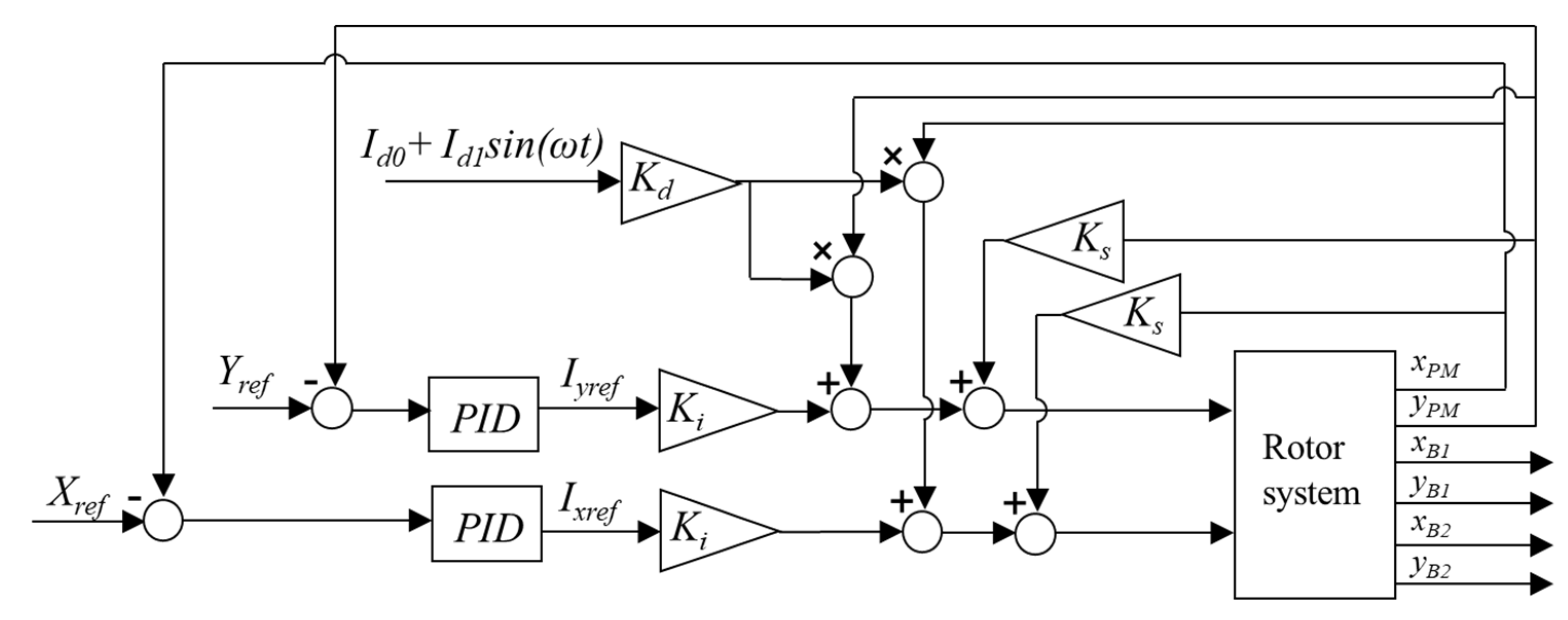
2.2. Algorithm for Estimating the Dynamic Parameters of the Bearing

In our research, the algorithm for estimating the dynamic parameters of the bearing is based on the FE model of the rotor system. For a rotor supported by two oil-film bearings, the equations of motion can be expressed as
M q ¨ + ( Ω G + C B ) q ˙ + ( K + K B ) q = F u + F m
where M, K, and G are the mass, stiffness, and gyroscopic matrices of the rotor; Fu and Fm are the unbalanced force and motor force vector, respectively; q is the generalized displacement vector; Ω is the rotational speed of the rotor; KB and CB are the stiffness and damping matrices of the two bearings, which can be written as
K B = [ K b 1 K b 2 ] ; C B = [ C b 1 C b 2 ]
with
K b i = [ k x x k x y k y x k y y ] , C b i = [ c x x c x y c y x c y y ] , i = 1 , 2
where kxx, kxy, kyx, kyy are the stiffness parameters of the bearing; cxx, cxy, cyx, cyy are the damping parameters of the bearing.
The stiffness and damping of the bearing are considered to be linear at a fixed speed. Therefore, the bearing force can be expressed as
F b = K B q B C B q ˙ B
where qB is the bearing displacement vector. Substituting Equation (5) into Equation (2), Equation (2) can be rewritten as
M q ¨ + Ω G q ˙ + K q = F u + F m + F b
Because of the limitation of the number of measurement points in a practical rotor system, dynamic condensation is used to reduce the DOFs in the FE equation, enabling us to estimate the dynamic parameters of the bearings. The transformation is defined as
q = { q m q s } = T d q m
where
T d = [ I K s s 1 K s m ] ; q m = { q b 1 q b 2 q P M }
where Td is the transformation matrix. The subscripts m and s are the master and slave DOFs, respectively. qb1 and qb2 are the measured displacement vectors of the support points of the bearings; qPM is the measured displacement vector of the PM motor rotor. These displacement vectors are expressed as
q b 1 = [ x B 1 y B 1 ] T ; q b 2 = [ x B 2 y B 2 ] T ; q P M = [ x P M y P M ] T
where xB1,2 and yB1,2 are the measured translational displacements of the two bearings in the horizontal and vertical directions; xPM and yPM are the measured translational displacements of the PM motor rotor in the horizontal and vertical directions.
After substituting Equation (7) into Equation (6), Equation (6) can be rewritten as
M d q ¨ m + Ω G d q ˙ m + K d q m = F d
with
M d = ( T d ) T M R T d , K d = ( T d ) T K R T d G d = ( T d ) T G R T d , F d = ( T d ) T ( F u + F m + F b )
where Fd and qm are the force and displacement vectors, respectively. Md, Kd, and Gd are the condensed mass, stiffness, and gyroscopic matrices, respectively.
In general, F(t) = Fejωt, and the response has the same frequency as the excitation q(t) = qejωt. Therefore, Equation (2) can be expressed as
( ω 2 M d + j ω Ω G d + K d ) q m = F d
According to Equation (12), the transfer function between the excitation force and the rotor displacement is
H = ( ω 2 M d + j ω Ω G d + K d )
Therefore, Equation (12) can be rewritten as
H { q b 1 q b 2 q P M } = { F b 1 F b 2 F P M }
where Fb1 and Fb2 are the bearing force vectors; FPM is the excitation force vector.
Because the H matrix can be partitioned into sub-matrices, Equation (14) can be rewritten as below:
[ H 11 H 12 H 13 H 21 H 22 H 23 H 31 H 32 H 33 ] { q b 1 q b 2 q P M } = { F b 1 F b 2 F P M }
According to Equation (15), the bearing forces can be derived from the measured responses at the bearing and motor positions without knowing the excitation force. The bearing forces can be obtained from the first and second rows of Equation (15):
F b 1 = H 11 q b 1 + H 12 q b 1 + H 13 q P M F b 2 = H 21 q b 1 + H 22 q b 1 + H 23 q P M
Similarly, according to Equation (5), the bearing force can also be expressed as
( K b 1 + j ω C b 1 ) q b 1 = F b 1 = H 11 q b 1 + H 12 q b 1 + H 13 q P M ( K b 2 + j ω C b 2 ) q b 2 = F b 2 = H 21 q b 1 + H 22 q b 1 + H 23 q P M
In order to obtain a sufficient number of equations to derive the total eight stiffness and eight damping parameters of both side bearings, excitation forces with different frequencies are required to produce two linearly independent rotor responses. For example, the frequencies of the two excitations are ω1 and ω2, and the displacements of the bearing journal are [qb1ω1 qb2ω1]T and [qb1ω2 qb2ω2]T with corresponding reaction forces [Fb1ω1 Fb2ω1]T and [Fb1ω2 Fb2ω2]T. With this information, the stiffness and damping parameters of the bearings can be obtained by solving Equation (18):
[ k x x 1 + j ω c 1 x x 1 k x y 1 + j ω c 1 x y 1 k y x 1 + j ω c 1 y x 1 k y y 1 + j ω c 1 y y 1 k x x 1 + j ω c 2 x x 1 k x y 1 + j ω c 2 x y 1 k y x 1 + j ω c 2 y x 1 k y y 1 + j ω c 2 y y 1 ] = [ F b 1 ω 1 F b 1 ω 2 ] [ q b 1 ω 1 q b 1 ω 2 ] 1 [ k x x 2 + j ω c 1 x x 2 k x y 2 + j ω c 1 x y 2 k y x 2 + j ω c 1 y x 2 k y y 2 + j ω c 1 y y 2 k x x 2 + j ω c 2 x x 2 k x y 2 + j ω c 2 x y 2 k y x 2 + j ω c 2 y x 2 k y y 2 + j ω c 2 y y 2 ] = [ F b 2 ω 1 F b 2 ω 2 ] [ q b 2 ω 1 q b 2 ω 2 ] 1
The required response information for estimating the dynamic parameters of the bearings can be obtained from the measured frequency responses at the motor and bearing locations.

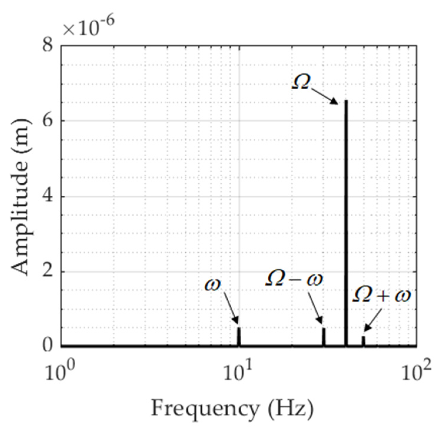
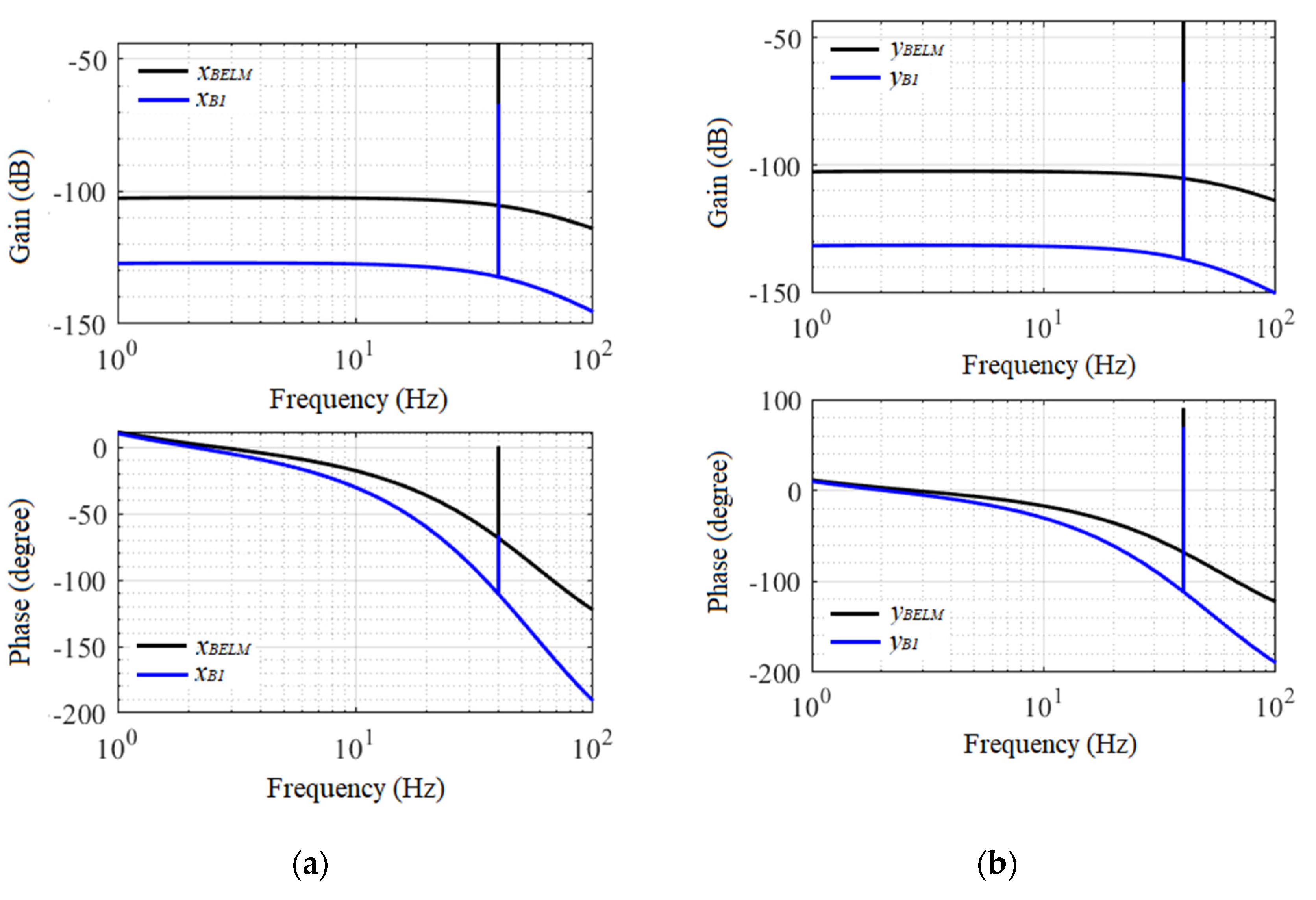
3. Numerical Evaluation

To evaluate the feasibility of the proposed method, numerical simulation and experiments were carried out on a flexible rotor test rig, as shown in Figure 2. The test rig consists of two cylindrical oil-film bearings and a bearingless motor (BELM). The BELM is a consequent-pole bearingless motor, which is placed between the two bearings. There are six pairs of eddy-current displacement sensors (PU-05, Applied Electronics Corp.) in the test rig. The displacement response of the BELM and the bearings were obtained by averaging the displacement signals from pairs of sensors placed on each side of the BELM and the bearings.
Unlike general PM motors, the BELM combines a radial active magnetic bearing (AMB) and a PM motor. The BELM has suspension windings for the radial AMB function and independent motor windings for rotation. The estimates of the parameters of the bearing obtained utilizing the excitation force generated by the suspension windings are regarded as being reference parameters. The estimates utilizing the excitation force generated by the motor windings are compared with the reference results.
The FE model of the rotor and the measured responses at the locations of the motor (BELM) and the oil-film bearings are used to estimate the dynamic parameters. The accuracy of the FE model of the rotor is verified by a modal test. Table 1 shows the measured free-free modal frequencies of the rotor, which show that the maximum relative error is within 2%.
The FE model employed to obtain the rotor displacement responses of the rotor was compiled in SIMULINK® (SIMULINK R2016b, The Mathworks, Inc, Tokyo, Japan). A block diagram of the rotor system is shown in Figure 3. The suspension windings of the BELM are arranged as three-phase windings, and the suspension currents are determined by the transformation from two-phase to three-phase. The radial force variations caused by the rotor rotation are minimized by this arrangement of suspension windings [20]. Therefore, the radial AMB function of the BELM is considered to have linear current–force coefficients (Ki) and linear displacement–force coefficients (Ks) in the horizontal and vertical directions. A proportional–integral–derivative (PID) controller was employed for the rotor suspension. The transfer function of the controller is
C ( s ) = P + I s + D N f s N f + s
where P, I, and D are the proportional, integral, and derivative coefficients; Nf is the filter coefficient.
The physical properties and dimensions of the rotor system are shown in Table 2, and the main parameters used for simulation are shown in Table 3. The residual unbalanced force is added onto the BELM node. The current–force coefficient, displacement–force coefficient, and the PID controller parameters are the same in both the horizontal and vertical directions. The simulated rotational speed was set at 2400 rpm. The Runge–Kutta method was used to solve the equation of the system.
To obtain the frequency response for estimating the dynamic parameters of the bearing, spring and damping elements with assumed dynamic parameters were added to the corresponding nodes of the FE model. In simulating the eccentricity of the rotor, the reference position for the BELM rotor center was set at (−50 μm, −50 μm). Figure 4 shows the FFT results for the displacement at Bearing 1 in the X-direction when the Id1 current frequency is 10 Hz.
From the results, it can be seen that the response has four frequency components: ω, Ω-ω, Ω, and Ω + ω. The maximum amplitude at Ω is due to the synchronous unbalance force. The vibrations at frequencies of ω, Ω-ω, and Ω + ω are generated by injecting a d-axis current and the eccentricity of the motor rotor.
Figure 5 shows the simulated frequency response characteristics of the BELM rotor and Bearing 1 when an excitation current is applied. The unit of gain is meter/ampere (m/A). The range of the excitation frequency is from 1 to 100 Hz. As seen in Figure 5, the displacement and phase information of the rotor at different frequencies can be obtained. According to the algorithm proposed in Section 2.2, two linearly independent rotor responses are required to estimate eight stiffness and eight damping parameters of both side bearings. Here, only the displacement and phase data at the excitation frequencies of 25 Hz and 26 Hz were used to estimate the dynamic parameters of the bearing because the estimations are the same when using the response data at other frequencies.
Based on the algorithm proposed in Section 2.2, the dynamic parameters of the bearing are estimated from the simulated response data. Table 4 shows a comparison of the estimated and assumed values of the dynamic parameters of the bearing.
According to the estimates, it is clear that the dynamic parameters of the bearing estimated by the proposed method are almost the same as the assumed values.

4. Experiment Evaluation

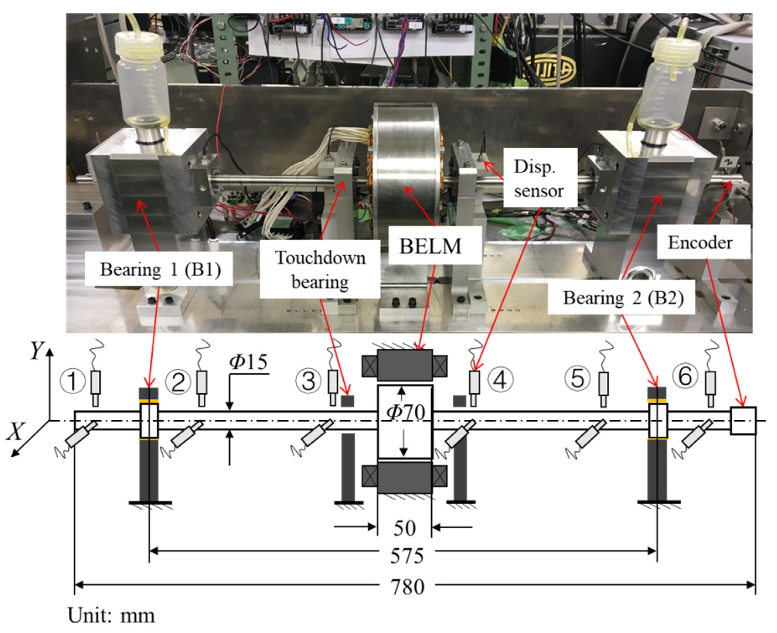
4.1. Experimental Method

Two experiments were carried out on the test rig shown in Figure 2 to verify if the estimated dynamic parameters were reasonable. Figure 6 shows the signal flow. There are two types of windings in the BELM: one is the motor windings, and the other is the suspension windings. The motor windings are three-phase and have eight poles. The suspension windings are three-phase and have two pairs of poles. A DSP system (MicroLabBox, dSPACE, GmbH.) with a sampling frequency of 20 kHz is used to control the BELM. Three PWM amplifiers (Junus JSP-180-20, Copley Controls Corp.) generate current for the suspension. The bandwidth of the current feedback system is about 600 Hz, and the coefficients of the PID controller are the same as used in simulating the FE model of the rotor described in Section 3. For the motor, a current amplifier (7425 AC, Copley Controls Corp.) generates three-phase current, and the bandwidth of the current feedback system is about 1000 Hz.
In Experiment 1, the excitation force was generated by the motor windings of the BELM. In Experiment 2, the excitation force was generated by the suspension windings of the BELM. The estimates obtained from Experiment 2 are regarded as reference values.
In Experiments 1 and 2, the rotational speed of the rotor was set at 2400 rpm. The reference position Xref and Yref of the motor center is defined when the control current of the suspension winding is zero, which is obtained by a zero-power controller. The application of the zero-power controller balances the external forces acting on the rotor, such as the gravitational force, which causes a nonuniform air gap in the motor. Therefore, the reference position defined by the zero-power controller leads to eccentricity. With eccentricity, an excitation force can be generated by injecting a d-axis current into the motor windings.
In both experiments, the reference position was the same, the excitation frequency range was 5 to 100 Hz, and an offset of −4 A was set to the d-axis current (Id0).
In Experiment 1, the d-axis current added to the motor windings is
I d = I d 0 + I d 1 sin ω t
where Id0 is the offset to the d-axis current; Id1 is the amplitude of the sinusoidal excitation current; ω is the excitation frequency. The offset applied to the d-axis current was −4 A, and the amplitude of the sinusoidal d-axis current was 4 A.
In Experiment 2, the excitation currents added to the suspension windings in the two directions are as follows:
{ I x I y } = { I e sin ω t I e cos ω t }
where Ix and Iy are the excitation currents in the horizontal and vertical directions, respectively; Ie is the amplitude of the excitation current. The amplitude of the excitation current Ie in the two directions was 0.5 A.

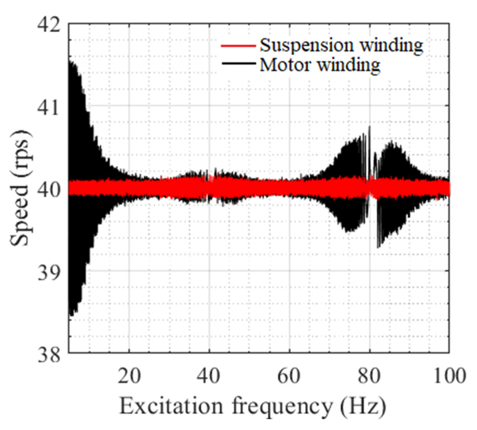
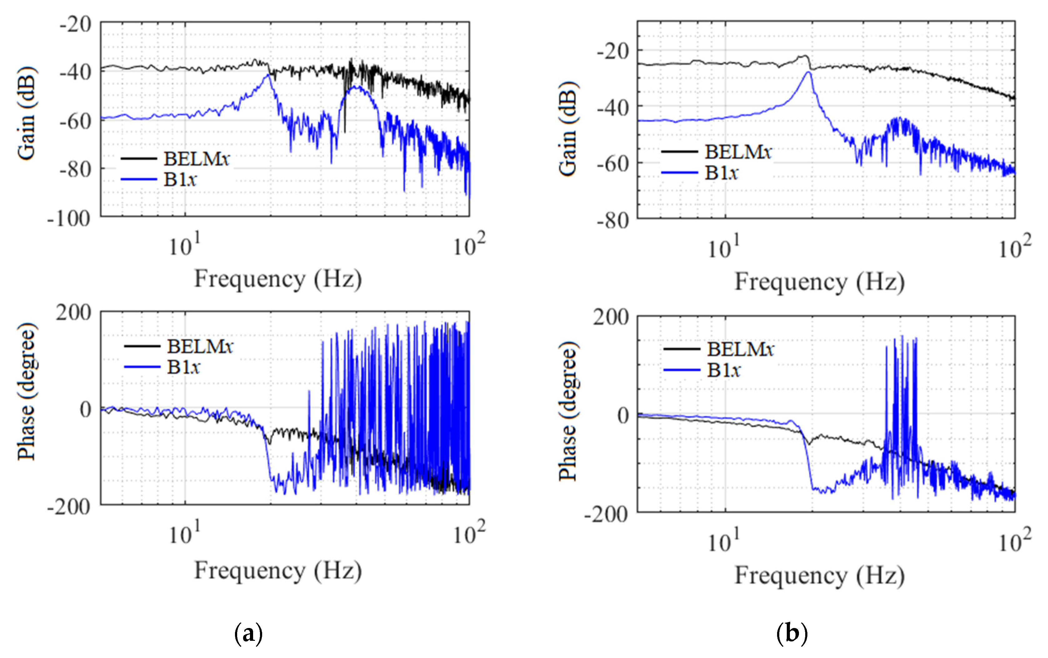
4.2. Results of the Experiments

Figure 7 shows the measured frequency response characteristics of the BELM rotor and Bearing 1 in the X-direction using excitation forces generated by the suspension windings and the motor windings. The unit of gain is millimeter/ampere (mm/A). Comparison of the frequency responses of the two experiments shows that the phases of the response of the BELM and Bearing 1 in the two experiments are similar. The difference in the amplitude offset is caused by the difference in the current–force coefficients for the excitation forces generated by the motor windings and suspension windings.
There are two peaks in the experimental bearing responses. The first one is the resonance frequency at about 19.4 Hz. The other is at about 40 Hz due to the synchronous unbalance force. The responses at the BELM rotor and the bearing positions are different because the radial AMB function of the BELM provides additional stiffness and damping, which changes the response at the BELM rotor position. Thus, the radial AMB function of the BELM has a substantial influence on the characteristics of the oil film.
Figure 8 shows the measured displacement frequency responses of the two bearings in the X-direction in Experiment 1. The responses of the two bearings are similar because the test rig is nearly symmetrical; the force is applied at the center of the rotor and the experimental conditions are the same.
Because the experimental data contains noise, deviations in the amplitude and phase caused by the measurement noise result in estimation errors. Therefore, after obtaining the frequency responses, the least-squares method was used to fit the measured results using a frequency response function G(). A high-order function can improve the fitting accuracy, but it is more sensitive to measurement noise. Because both the characteristics of the bearings and the BELM affect the response of the rotor, a fourth-order function was adopted for fitting in our experiment.
G ( j ω ) = a 1 ( j ω ) + a 2 b 1 ( j ω ) 4 + b 2 ( j ω ) 3 + b 3 ( j ω ) 2 + b 4 ( j ω ) + b 5
From Equation (22), the phase and amplitude of the displacement response at each excitation frequency can be obtained through the parameters a1, a2, b1, b2, b3, b4, and b5.
The amplitude and phase information of the responses at different frequencies can be acquired through G(). In this work, due to the insufficient sensor resolution, the frequency response from 5 Hz to 40 Hz was used for fitting; this reduces the fitting error caused by the large phase deviation. The measured and fitted results of the BELM rotor and Bearing 1 are shown in Figure 9 and Figure 10, respectively.
Figure 11 shows the rotational speeds with and without injection of the alternating d-axis current. The frequency of the d-axis current has a significant influence on the fluctuations in rotational speed. The maximum error is about 1.5 rps at 5 Hz. The error gradually decreases with increasing excitation frequency. However, the error increases when the frequency is close to a multiple of the rotational speed. Therefore, to prevent the effect of these fluctuations on the estimates, response data between 22 Hz and 26 Hz, where the speed is stable, were used to estimate the dynamic parameters of the bearings.
We assumed that the dynamic parameters of the bearings are constant over a small range of excitation frequencies. For example, the amplitude and phase information at 22 Hz and 22.1 Hz were used to estimate the dynamic parameters at 22 Hz. The same procedure was used to estimate the bearing dynamic parameters at other frequencies.
Figure 12 shows the estimates for the two bearings in Experiment 1. The dynamic parameters of the two bearings are close because the test rig is nearly symmetrical, and the experimental conditions for the two bearings are the same.
In our test rig, the estimated stiffness parameters kxx and kyx are much bigger than kxy and kyy, and the damping parameters cxy and cyy are much bigger than cyx and cxx, which is not typical for oil-film bearings. Since the rotor is suspended by the radial AMB function of the BELM in our experiments, the eccentricity and additional stiffness and damping provided by the AMB have a substantial influence on the characteristics of the oil film. The force generated by the oil film is small, and the oil film only provides damping to reduce vibration in the Y-direction due to the suspension function. Therefore, the suspension of the rotor has a significant influence on the characteristics of the oil film.
The dynamic parameters of Bearing 1 estimated in the two experiments are shown in Figure 13. The percentage deviations of the mean value of the estimated dynamic parameters in the two experiments are listed in Table 5.
It can be seen that there is good agreement between the two experiments for most of the stiffness and damping coefficients, with a maximum error of 8.92%. The errors for kxy, kyy, and cxx are relatively large. This is because the base values of these coefficients are small, so that they are more sensitive to deviations.
To evaluate the influence of the deviations in the estimated bearing parameters on the rotor dynamic characteristics in the two experiments, the bearing dynamic parameters estimated in the two experiments were applied to the FE model of the rotor to calculate the natural frequency of the rotor system.
The FE model of the rotor before dynamic condensation was used to simulate the natural frequencies. The main parameters for simulation are those shown in Table 3. Table 6 lists the first three bending modal frequencies.
The results show that the natural frequencies calculated from the dynamic parameters of the bearings estimated in the two experiments are in good agreement, with a maximum relative error of 3.04%. Therefore, we believe that the estimates made using the proposed method are reliable for a general rotor-bearing system driven by a built-in motor.

5. Conclusions and Discussion

In this paper, we proposed a method for estimating the dynamic parameters of the bearings in a flexible rotor system based on the excitation force generated by a built-in PM motor. The excitation force is generated by injecting an alternating d-axis current into the motor windings. An FE model of the rotor and the measured frequency response of the rotor are used to estimate the dynamic parameters of the bearings. A flexible rotor combined with a BELM having a PM motor and radial magnetic bearings is employed for numerical simulation and experiments.
The numerical simulation results show that the proposed method can accurately estimate the dynamic parameters of the bearings. In the experimental work, to evaluate the feasibility of the proposed method, comparisons were made between the results estimated using the frequency responses measured when using the motor windings of the BELM for excitation and those generated using the suspension windings.
Comparison with the stiffness and damping coefficients estimated from the frequency responses measured when current is applied to the suspension windings shows that most of the stiffness and damping coefficients were estimated to within an error of 8.92% or less. The errors of some coefficients are large (kxy 19.03%, kyy −33.11%, and cxx 58.87%) because the base values of these coefficients are small in our test rig, so these coefficients are sensitive to deviations. The natural frequencies calculated from the estimated dynamic parameters of the bearings in the two experiments are in good agreement, within a maximum relative error of 3.04%. Therefore, the proposed method is significant for field tests.
Although safe, low-cost, and real-time tests can be carried out using this method, it still has shortcomings. This paper uses an alternating d-axis current to vary the bias magnetic flux to generate an alternating radial force. However, excessive d-axis current causes demagnetization of the permanent magnet, and a too-small d-axis current would not have a noticeable impact on the response of the rotor. As the displacement cannot be measured directly at the bearings and motor locations, the displacement responses are obtained by averaging the displacement signals from pairs of sensors placed on each side of the bearings and the motor. Therefore, it is necessary to develop a displacement measurement method with a small number of sensors to measure the displacement response at the bearings and motor locations, or to develop a sensorless method. The FE model of the rotor is used to estimate the dynamic parameters of the bearings, and the accuracy of the model is verified by experimental modal analysis. It is necessary to investigate the modeling errors on the accuracy of the estimated parameters. These remaining problems will be addressed in our future research.

Author Contributions

Conceptualization and methodology, Y.C.; software, validation, formal analysis, and investigation, Y.C. and R.Y.; writing—original draft preparation, Y.C., J.Z. and N.S.; writing—review and editing and supervision, T.S. and J.M. All authors have read and agreed to the published version of the manuscript.

Funding

NSK foundation for the advancement of mechatronics.

Institutional Review Board Statement

Not applicable.

Informed Consent Statement

Not applicable.

Data Availability Statement

Not applicable.

Acknowledgments

The authors would like to acknowledge the support from the China Scholarship Council (No.201906280434).

Conflicts of Interest

The authors declare no conflict of interest.

References

  1. Lund, J.W. Review of the concept of dynamic coefficients for fluid film journal bearings. ASME J. Tribol. 1987, 109, 37–41. [Google Scholar] [CrossRef]
  2. Tiwari, R.; Lees, A.W.; Friswell, M.I. Identification of dynamic bearing parameters: A review. Shock. Vib. Dig. 2004, 36, 99–124. [Google Scholar] [CrossRef]
  3. Goodwin, M.J. Experimental Techniques for Bearing Impedance Measurement. J. Manuf. Sci. Eng. 1991, 113, 335–342. [Google Scholar] [CrossRef]
  4. Childs, D.; Joel, H. Static performance characteristics and rotordynamic coefficients for a four-pad ball-in-socket tilting pad journal bearing. J. Eng. Gas Turbines Power 2009, 131, 062502. [Google Scholar] [CrossRef]
  5. Jiang, G.; Hu, H.; Xu, W.; Jin, Z.; Xie, Y. Identification of oil film coefficients of large journal bearings on a full-scale journal bearing test rig. Tribol. Int. 1997, 30, 789–793. [Google Scholar] [CrossRef]
  6. Xu, Y.; Zhou, J.; Lin, Z.; Jin, C. Identification of dynamic parameters of active magnetic bearings in a flexible rotor system considering residual unbalances. Mechatronics 2018, 49, 46–55. [Google Scholar] [CrossRef]
  7. Tiwari, R.; Lees, A.; Friswell, M. Identification of speed-dependent bearing parameters. J. Sound Vib. 2002, 254, 967–986. [Google Scholar] [CrossRef] [Green Version]
  8. De Santiago, O.C.; San Andrés, L. Field methods for identification of bearing support parameters part i: Identification from transient rotor dynamic response due to impacts. J. Eng. Gas Turbines Power 2007, 129, 205–212. [Google Scholar] [CrossRef]
  9. De Santiago, O.C.; San Andrés, L. Field methods for identification of bearing support parameters part ii: Identification from rotor dynamic response due to imbalances. J. Eng. Gas Turbines Power 2007, 129, 213–219. [Google Scholar] [CrossRef]
  10. San Andrés, L.; De Santiago, O.C. Identification of bearing force coefficients from measurements of imbalance response of a flexible rotor. In Proceedings of the ASME Turbo Expo 2004: Power for Land, Sea, and Air, Vienna, Austria, 14–17 June 2004; Volume 41677, pp. 843–850. [Google Scholar]
  11. Matsubara, A.; Tsujimoto, S.; Kono, D. Evaluation of dynamic stiffness of machine tool spindle by non-contact excitation tests. CIRP Ann. 2015, 64, 365–368. [Google Scholar] [CrossRef]
  12. Wang, W.; Li, Q.; Gao, J.; Yao, J.; Allaire, P. An identification method for damping ratio in rotor systems. Mech. Syst. Signal Process. 2016, 68, 536–554. [Google Scholar] [CrossRef]
  13. Li, Q.; Wang, W.; Weaver, B.; Wood, H. Model-Based Interpolation-Iteration Method for Bearing Coefficients Identification of Operating Flexible Rotor-Bearing System. Int. J. Mech. Sci. 2017, 131, 471–497. [Google Scholar] [CrossRef]
  14. Tsunoda, W.; Wagner, C.; Berninger, T.; Thuemmel, T.; Rixen, D. Stability Diagnosis for Rotor–Seal System by Utilizing Active Magnetic Bearing. In Proceedings of the XVII International Symposium on Dynamic Problems of Mechanics DINAME, Sao Sebastiao, Brazil, 5–10 March 2017. Paper No. DINAME2017-0048. [Google Scholar]
  15. Tsunoda, W.; Hijikata, W.; Shinshi, T.; Fujiwara, H.; Matsushita, O. Diagnostic Experiments for Stability of Rotor-Oil Film Bearing Systems Using Radial Magnetic Bearing Excitation. In Proceedings of the Vibrations in Rotating Machinery (VIRM11) conference, Manchester, UK, 13–15 September 2016. [Google Scholar]
  16. Chen, Y.; Yang, R.; Sugita, N.; Mao, J.; Shinshi, T. Identification of Bearing Dynamic Parameters and Unbalanced Forces in a Flexible Rotor System Supported by Oil-Film Bearings and Active Magnetic Devices. Actuators 2021, 10, 216. [Google Scholar] [CrossRef]
  17. Tsunoda, W.; Chiba, A.; Shinshi, T. Frequency Response Function Measurement Utilizing Radial Excitation Force Generated by Permanent Magnet Synchronous Motor. Mechatronics 2019, 61, 49–57. [Google Scholar] [CrossRef]
  18. Yang, R.; Tsunoda, W.; Han, D.; Zhong, J.; Shinshi, T. Frequency response function measurement of a rotor system utilizing electromagnetic excitation by a built-in motor. J. Adv. Mech. Des. Syst. Manuf. 2020, 14, AMDSM0043. [Google Scholar] [CrossRef] [Green Version]
  19. Tsunoda, W.; Chiba, A.; Shinshi, T. Radial Excitation Force Generated by Permanent Magnet Motor Using d-Axis Current Injection. In Proceedings of the IEEE International Conference on Industrial Technology (ICIT), Lyon, France, 20–22 February 2018; pp. 504–509. [Google Scholar]
  20. Takenaga, T.; Kubota, Y.; Chiba, A.; Fukao, T. A principle and a design of a consequent-pole beaingless motor. In Proceedings of the 8th International Symposium on Magnetic Bearing, Mito, Japan, 26–28 August 2002. [Google Scholar]
Figure 1. The magnetic flux flow of a PM motor with eccentricity in the X-direction.
Actuators 11 00001 g001
Figure 2. The experimental test rig.
Actuators 11 00001 g002
Figure 3. Block diagram of the rotor system.
Actuators 11 00001 g003
Figure 4. FFT result of the simulated displacement of Bearing 1 in the X-direction.
Actuators 11 00001 g004
Figure 5. Simulated frequency responses of the BELM rotor and Bearing 1. (a) Simulated frequency responses of the BELM rotor and Bearing 1 in the X-direction; (b) Simulated frequency responses of the BELM rotor and Bearing 1 in the Y-direction.
Actuators 11 00001 g005
Figure 6. The signal flow for the experiments using excitation forces generated by the motor windings (Experiment 1) and the suspension windings (Experiment 2), respectively.
Actuators 11 00001 g006
Figure 7. Measured frequency responses of the BELM rotor and Bearing 1 in the X-direction using excitation forces generated by the motor windings and the suspension windings. (a) Measured frequency responses of the BELM rotor and Bearing 1 in Experiment 1; (b) Measured frequency responses of the BELM rotor and Bearing 1 in Experiment 2.
Actuators 11 00001 g007
Figure 8. Measured frequency responses of the two bearings in the X-direction using the excitation force generated by the motor windings.
Actuators 11 00001 g008
Figure 9. Measured and fitted responses of the BELM rotor. (a) Measured and fitted response of the BELM rotor in the X-direction; (b) Measured and fitted response of the BELM rotor in the Y-direction.
Actuators 11 00001 g009
Figure 10. Measured and fitted responses of Bearing 1. (a) Measured and fitted response of Bearing 1 in the X-direction; (b) Measured and fitted response of Bearing 1 in the Y-direction.
Actuators 11 00001 g010
Figure 11. Rotational speed with and without injection of the alternating d-axis current.
Actuators 11 00001 g011
Figure 12. Estimates for the two bearings in Experiment 1. (a) Estimated stiffness coefficients of two bearings; (b) Estimated damping coefficients of two bearings.
Actuators 11 00001 g012
Figure 13. Comparisons of the dynamic parameters of Bearing 1 estimated in the two experiments. (a) Estimated stiffness coefficients of Bearing 1; (b) Estimated damping coefficients of Bearing 1.
Actuators 11 00001 g013
Table 1. Measured and simulated modal frequencies.
ModalMeasured FrequencyCalculated
Frequency
Error
183.3 Hz82.9 Hz−0.48%
2268.2 Hz269.8 Hz0.59%
3510.8 Hz507.5 Hz−0.64%
4770.5 Hz756.5 Hz−1.82%
Table 2. Specifications of the rotor system.
ComponentsParametersValues
RotorLength780 mm
Diameter15 mm
Young’s modulus2.05 × 1011 N/m2
Mass density7850 kg/m3
Poisson’s ratio0.29
Oil-film bearingLength25 mm
Diameter25 mm
Clearance0.1 mm
MotorRotor length50 mm
Rotor diameter70 mm
Table 3. Main parameters for simulation.
ParametersFirst Set
Proportional (P)52,000
Integral (I)17,500
Derivative (D)60
Filter coefficient (Nf)12,560
Current–force coefficient (Ki)26.4 N/A
Displacement–force coefficient (Ks)1.27 × 10⁶ N/m
Eccentricity–current–force coefficient (Kd)1.17 × 10⁴ N/A·m
Bias current (Id0)−4 A
Excitation current amplitude (Id1)4 A
Unbalance moment (mr)6 × 10⁻⁴ kgm
Table 4. Assumed and estimated stiffness and damping parameters of the two bearings.
ParametersBearing 1Bearing 2
AssumedEstimatedAssumedEstimated
Stiffness
(N/m)
kxx1 × 1061.000 × 1061.2 × 1061.200 × 105
kxy5 × 1054.999 × 1055 × 1054.999 × 105
kyx6 × 1056.000 × 1058 × 1058.000 × 105
kyy1.2 × 1061.199 × 1061.4 × 1061.399 × 105
Damping
(N.s/m)
cxx40004000.0050005000.00
cxy15001499.991000999.99
cyx20002000.0020002000.00
cyy50004999.9940003999.99
Table 5. Percentage deviations of the mean value of the estimates in the two experiments.
Stiffness
(N/m)
Exp. 1Exp. 2ErrorDamping
(N.s/m)
Exp. 1Exp. 2Error
kxx7.92 × 1058.11 × 105−2.37%cxx4.95 × 1023.12 × 10258.87%
kxy8.97 × 1047.54 × 10419.03%cxy5.57 × 1035.79 × 103−3.81%
kyx9.38 × 1059.29 × 1051.02%cyx7.84 × 1027.21 × 1028.92%
kyy2.33 × 1043.12 × 104−33.11%cyy6.19 × 1036.21 × 1030.31%
Table 6. Percentage deviations of the calculated natural frequencies.
ModalCalculated Natural Frequency
(Parameters from Exp. 1)
Calculated Natural Frequency
(Parameters from Exp. 2)
Error
147.82 Hz46.41 Hz3.04%
58.27 Hz58.26 Hz0.02%
2262.09 Hz262.48 Hz−0.15%
271.63 Hz272.16 Hz−0.19%
3461.34 Hz461.33 Hz0.01%
505.91 Hz506.84 Hz−0.18%
Publisher’s Note: MDPI stays neutral with regard to jurisdictional claims in published maps and institutional affiliations.

