Article

Adaptive Fuzzy Active-Disturbance Rejection Control-Based Reconfiguration Controller Design for Aircraft Anti-Skid Braking System

1
College of Automation Engineering, Nanjing University of Aeronautics and Astronautics, Nanjing 211106, China
2
Research Institute of UAV, Nanjing University of Aeronautics and Astronautics, Nanjing 211106, China
3
Electronic Engineering Department, Aviation Key Laboratory of Science and Technology on Aero Electromechanical System Integration, Nanjing 211106, China
*
Author to whom correspondence should be addressed.
Actuators 2021, 10(8), 201; https://doi.org/10.3390/act10080201
Submission received: 22 July 2021 / Revised: 13 August 2021 / Accepted: 19 August 2021 / Published: 22 August 2021
(This article belongs to the Special Issue Robust, Fault-Tolerant Control Design)

Abstract

:
The aircraft anti-skid braking system (AABS) is an essential aero electromechanical system to ensure safe take-off, landing, and taxiing of aircraft. In addition to the strong nonlinearity, strong coupling, and time-varying parameters in aircraft dynamics, the faults of actuators, sensors, and other components can also seriously affect the safety and reliability of AABS. In this paper, a reconfiguration controller-based adaptive fuzzy active-disturbance rejection control (AFADRC) is proposed for AABS to meet increased performance demands in fault-perturbed conditions as well as those concerning reliability and safety requirements. The developed controller takes component faults, external disturbance, and measurement noise as the total perturbations, which are estimated by an adaptive extended state observer (AESO). The nonlinear state error feedback (NLSEF) combined with fuzzy logic can compensate for the adverse effects and ensure that the faulty AABS maintains acceptable performance. Numerical simulations are carried out in different runway environments. The results validate the robustness and reconfiguration control capability of the proposed method, which improves AABS safety as well as braking efficiency.

1. Introduction

An aircraft anti-skid braking system (AABS) with good performance is an important guarantee for the successful completion of flight missions [1]. It directly affects the safety of the aircraft and the crew on board. With the rapid development of the aviation industry, the demand for large-tonnage and high-velocity aircraft is increasing. In order to brake this type of aircraft in less time and over shorter distances, it is necessary to improve the efficiency and performance of AABS. Moreover, the AABS is highly non-linear and subject to many uncertainties including runway surface conditions, which makes the AABS controller design challenging [2].
The conventional PID + PBM control [3] method does not work well on runways with disturbances, and the aircraft suffers from low-speed slippage [4,5]. In response to these problems, many control schemes proposed by researchers have been widely applied in the field of AABS, such as mixed slip deceleration PID control [6], backstepping dynamic surface control [7], optimal fuzzy control [8], self-learning fuzzy sliding mode control [9], direct adaptive fuzzy–neural control [10] and so on. Chen X. et al. proposed an asymmetric barrier Lyapunov-function-based wheel slip controller for AABS, and the braking system operating status was effectively constrained to the healthy region and the light slip region [11]. Considering the need to make the brake control more resistant to disturbances, Li F. B. et al. designed a nonlinear observer for online estimation of disturbances and introduced a fast terminal sliding mode controller to track the optimal slip rate that changes in real time [12]. Despite the above-mentioned works that have made an in-depth study on AABS control, the faults of electro-hydraulic actuators, speed sensors, and other system components are deemphasized, leaving AABS still with many security risks. Aiming to really improve the safety and reliability, the AABS can be designed and configured from the hardware level on the one hand [13,14,15]. However, the demanding hardware experimental conditions limit the development of this method. On the other hand, as a popular branch of fault-tolerant control, reconfiguration control is widely applied to some safety-critical systems at present, especially in the field of aerospace engineering [16,17]. It seems reasonable and valid to introduce the concept of reconfiguration control into AABS. Moreover, this is also the future development direction of AABS and the key technology that needs urgent attention [18]. Therefore, this paper attempts to design a reconfiguration controller for AABS to meet the higher performance requirements in fault conditions as well as those concerning demands related to reliability and safety.
Han J. inherited the essence of the classical PID controller and proposed an active-disturbance rejection control (ADRC) technique that requires low model accuracy and is easy to implement [19,20]. ADRC is capable of estimating internal and external system disturbances in real time and compensating for them. Since ADRC has obvious advantages in solving control problems for nonlinear models with uncertainty and strong disturbances, this allows ADRC to be applied on a wide variety of plants [21,22,23]. Moreover, many excellent schemes combine ADRC with other advanced control methods, such as sliding mode ADRC [24], adaptive ADRC [25,26], fuzzy ADRC [27,28,29], Q-Learning ADRC [30] and so on, which make the controllers much more robust and adept at anti-disturbance. Qi et al. [31] proposed a BPNN-based adaptive ADRC controller wherein the ESO can be tuned online. Roman, R. C. et al. [32] introduced an ADRC controller combined with Takagi–Sugeno Fuzzy control and verified it in a tower crane system, which greatly enhances the controller robustness and ability to handle nonlinearity. A fuzzy logic-based ADRC controller is presented by Gai J. et al. [33] to improve the anti-load disturbance ability of permanent magnet synchronous motor. Currently, many researchers have used ADRC to solve the system component fault issues [34,35]. More importantly, ADRC has been introduced by Liu W. et al. for AABS and its good brake dynamic characteristics were validated [36]. Thus, it seems that it is feasible to design a reconfiguration controller for AABS based on the ADRC technique.
Motivated by the above observations, in this paper, a reconfiguration controller-based adaptive fuzzy active-disturbance rejection control (AFADRC) has been developed for AABS subject to various component faults. The proposed reconfiguration control method is a remarkable control strategy compared to previous methods for four reasons:
(i)
It is a robust control strategy, in which the AABS model is extended with a new state variable. This state variable is the sum of all unknown dynamics and disturbances that are not noticed in the fault-free plant description, and it is estimated online using the designed extended state observer (ESO), which indirectly simplifies the model to a significant extent.
(ii)
An adaptive extended state observer (AESO) is proposed to estimate the new state variable. The method is based on online tuning of ESO parameters using an improved back propagation neural network (BPNN). It should be noted that the proposed AESO is an improvement on the one presented by Qi et al. [31]. The application of AESO not only eliminates the tedious manual tuning of the parameters, but also greatly enhances the adaptiveness and robustness of the proposed method in the face of faults and disturbances.
(iii)
Fuzzy logic is introduced into the nonlinear state error feedback (NLSEF). The performance of the ADRC is heavily related to the selection of NLSEF parameters. ADRC with fixed parameters has limited robustness and anti-disturbance. It may lead to an unacceptable performance or even divergence in different fault perturbation cases. NLSEF combined with fuzzy logic can adjust the control law parameters online autonomously to meet the control performance requirements, which thereby improves controller robustness and parameter adaptiveness. It is worth mentioning that fuzzy logic is data-driven, making it immune to model errors caused by imprecise modeling.
(iv)
Additional fault detection and identification (FDI) modules are not required, and the controller parameters are adaptive. Therefore, the proposed AFADRC belongs to a novel combination of passive reconfiguration control and FDI-free reconfiguration control, which makes it an interesting solution in unknown fault conditions.
The paper is organized as follows. Section 2 describes AABS dynamics. The reconfiguration controller based on AFADRC is presented in Section 3. The simulation results are presented to demonstrate the merits of the proposed method in Section 4, and conclusions are drawn in Section 5.

2. AABS Dynamics

Previous studies have generally not considered the effect of the landing gear but have viewed the fuselage and landing gear as a rigid whole [11,12]. This simplified model of the brake system is not accurate enough to describe the actual system. In this paper, the dynamics modeling of an AABS generally includes aircraft fuselage dynamics, landing gear dynamics, individual main wheel braking dynamics, combination coefficients, and electro-hydraulic actuators. The subsystems are strongly coupled and exhibit strong nonlinearity and complexity.

2.1. Aircraft Fuselage Dynamics

Based on the actual process of anti-skid braking and objective facts, some reasonable assumptions can be made:
(i)
The aircraft fuselage is ideal rigid one with a concentrated mass.
(ii)
The gyroscopic moment generated by the engine rotor is not considered in the aircraft braking process.
(iii)
The system ignores the crosswind effect.
(iv)
The system ignores the tire deformation.
(v)
All wheels are the same and controlled synchronously.
The force diagram of the aircraft fuselage is shown in Figure 1, and the specific parameters described in the diagram are shown in Table 1. The force balance equation of the aircraft is:
T 0 F x F s f 1 f 2 = M x ¨ G F y N 1 N 2 = M y ¨ N 2 b cos θ + F s ( h s + h t ) N 1 a cos θ T 0 h t f 1 H f 2 H = I θ ¨
According to the influence of aerodynamic properties, we have the following equation:
T 0 = T 0 + K v V F x = 1 2 ρ C x S V 2 F y = 1 2 ρ C y S V 2 F s = 1 2 ρ C x s S s V 2
The combination coefficient μ i is defined as:
μ i = f i N i
where i = 1 , 2 .

2.2. Landing Gear Dynamics

The main function of the landing gear is the support and buffer action, thus improving the vertical and longitudinal force situation. In addition to the wheel and braking device, struts, buffer, and torque arm are the main components of the landing gear. In this paper, it is assumed that the stiffness of the torque arm is large enough and the torsional freedom of the wheel with respect to the strut and the buffer is ignored, so the torque arm is not considered.

2.2.1. Buffer Modeling

The buffer can be reasonably simplified to a mass-spring-damper system [37]. The force acting on the fuselage by the buffer can be described as:
N 1 = K 1 X 1 + C 1 X ˙ 1 2 N 2 = K 2 X 2 + C 2 X ˙ 2 2
X 1 = a sin θ + y X 2 = b sin θ + y
whose parameters are shown in Table 2.

2.2.2. Landing Gear Lateral Stiffness Modeling

Due to the nonrigid connection between the landing gear and aircraft, horizontal and angular displacements are generated under the action of braking force. However, the strut is a cantilever beam whose angular displacement is very small and negligible. The landing gear lateral stiffness model can be represented by the equivalent second-order equation as follows:
d a = f 1 K 0 1 W n 2 s 2 + 2 ξ W n s + 1 d V = d d t ( d a )
whose parameters are shown in Table 3.

2.3. Wheel Dynamic

The force analysis diagram of the main wheel brake is shown in Figure 2. During the taxiing, the main wheel is subjected to a combination of braking torque M s and ground friction torque M j . In addition, since the effect of lateral stiffness is considered for the main landing gear, there exists a wheel axle velocity V z x along the longitudinal direction of the airframe, obtained by superimposing the aircraft speed V and the navigation vibration speed d V . The main wheel dynamics equation is:
ω ˙ = M j M s J + V z x R g V w = ω × R g V z x = V + d V R g = R 1 4 N 1 k σ M j = μ N R g n
whose parameters are shown in Table 4.
When the wheel is braked, a longitudinal force is applied to the tire, always making V > V w . This difference can be expressed in terms of the slip rate λ . For the main wheel, using V z x instead of V to calculate λ can avoid the false brake release caused by landing gear deformation, thus effectively reducing the landing gear walk situation [37]. In this paper, λ can be calculated as follows:
λ = V z x V w V z x
The combination coefficient is related to the real-time runway status, aircraft speed, slip rate, and many other factors. In this paper, the magic formula given by Pacejka H. B. [38] is used to describe the model:
μ = D sin ( C arctg ( B λ ) )
where D is the peak factor, C is the stiffness factor, and B is the curve shape factor. By changing these factors, different ground combination coefficients can be modeled. The specific parameter values for several different runways are shown in Table 5.

2.4. Hydraulic Servo System Modeling

AABS working principle is introduced in advance: the controller controls the hydraulic servo system according to the error between the wheel speed and the aircraft speed, thus changing the brake pressure and realizing brake control. Since the structure of the hydraulic servo system is complex, in this paper, some simplifications have been made that only electro-hydraulic servo valve and pipes are considered. The transfer functions of them are expressed as follows:
M ( s ) = K s v s 2 ω s v 2 + 2 ξ s v s ω s v + 1 L ( s ) = K p T p s + 1
whose parameters are shown in Table 6.
It should be noted that the controller should realize both brake control and anti-skid control. To this end, there is an approximately relationship between the brake pressure P and the control current I c , which can be described as follows:
P = I c M ( s ) L ( s ) + 1 × 10 7
The braking device serves to convert the brake pressure into brake torque, and its calculation is as follows:
M s = μ m c N m c P R m c
whose parameters are also shown in Table 6.
The hydraulic servo system, as the actuators of AABS, is inevitably subject to potential faults. Problems such as hydraulic oil mixing with air, internal leakage, and vibration seriously affect the efficiency of the hydraulic servo system [13,14]. Therefore, in this paper, loss of effectiveness (LOE) is introduced to represent typical AABS actuator faults. The LOE fault is characterized by a decrease in the actuator gain from its nominal value [35]. In the case of an actuator LOE fault, the brake pressure generated by the AABS deviates from the commanded output expected by the controller. In other words, one instead has:
P f a u l t = k L O E P
where P f a u l t refers to the actuator actual output, P is the commanded output by the controller, k L O E represents the LOE fault gain, and k L O E ( 0 , 1 ) .
Remark 1.
n % LOE is equivalent to the LOE fault gain k L O E = 1 n 100 . For example, 20 % LOE represents k L O E = 0.8 .
Remark 2.
It should be noted that if the actuator does not have the same characteristics as fault-free, it is necessary to establish the fault model. Not only does this provide an accurate model for the next controller design, but it also ensures that the adverse effects caused by faults can be effectively estimated and compensated for.
Thus, Equation (12) can be rewritten as follows:
M s = μ m c N m c P f a u l t R m c
where M s is the actual brake torque.
Remark 3.
As can be seen from Equations (1)–(12), the fault-free AABS is nonlinear and highly coupled. The occurrence of the faults leads to a jump in the model parameters with greater internal perturbation compared to the no-fault case. Meanwhile, the external disturbance cannot be ignored.

2.5. Overall Components of Aircraft Anti-Skid Braking System

The overall components of AABS and the interaction between each part are summarized in Figure 3. It can be seen that AABS is a complex nonlinear system, whose variables affect and constrain each other. The controller design for AABS will be more challenging if actuator faults are considered.

3. Reconfiguration Controller Design

ADRC inherits the advantage of PID control, which is error-driven rather than model-based. There are some unique qualities in ADRC [35,39]: it offers an observer to estimate the disturbance; it combines the state feedbacks in a nonlinear way, allowing for a wide range of parameter adaptation; it is a digital control technique developed from the experimental platform rooted in computer simulations. The normal ADRC consists of a tracking differentiator (TD), a nonlinear state error feedback (NLSEF), and an extended state observer (ESO). However, the fixed controller parameters may not perform well in the face of faults that cause large jumps in model parameters. The normal ADRC requires many parameters to be tuned, which will increase the difficulty of engineering applications. Motivated by these facts, an AFADRC reconfiguration controller is proposed in this section—that is, using AESO instead of ESO to estimate the perturbations adaptively, and combining NLSEF with fuzzy logic to meet the control performance requirements under different fault and disturbance conditions.
Although the aircraft has three degrees of freedom, only longitudinal taxiing is focused on in AABS. According to Section 2, the AABS model can be written as follows:
x ¨ = f ( x , x ˙ , ϖ ) + b x u
where f ( ) is the uncertainty item, ϖ represents the total perturbations, b x = 1 m . Since AABS in this paper adopts the slip speed control type [1], system (15) can be rewritten as follows:
V ˙ = f ( x , V , ϖ ) + b v u
where b v = b x .
The structure of the AFADRC proposed in this paper is shown in Figure 4. For AABS, v 0 = V , u = I c and y ˜ = V w + V n , where V n denotes measurement noise. The design process is described in detail next.

3.1. Tracking-Differentiator (TD)

The main role of the TD is twofold: the first is to arrange the transition process for the system; the second is to filter the signal and obtain the differentiated signal. This effectively solves the conflict between rapidity and overshoot. A second-order TD can be designed as follows:
e ( k ) = v 1 ( k ) v 0 ( k ) fh = fhan ( e ( k ) , v 2 ( k ) , r , h ) v 1 ( k + 1 ) = v 1 ( k ) + h v 2 ( k ) v 2 ( k + 1 ) = v 2 ( k ) + h fh
where v 0 is the desired output, v 1 is the transition process of v 0 , v 2 is the derivative of v 1 , r and h are adjusted accordingly as filter coefficients. The function fhan ( ) is defined as follows:
fhan ( x 1 , x 2 , r , h ) = r sgn ( a ) , a > d 0 r a d , a d 0
with
d = r h d 0 = d h y ¯ = x 1 + h x 2 a 0 = ( d 2 + 8 r y ¯ ) 1 2 a = x 2 + a 0 d 2 , y ¯ > d 0 x 2 + y h , y ¯ d 0  

3.2. Adaptive-Extended-State-Observer (AESO)

ESO is the core of ADRC, which estimates the system states and the total disturbance in real time based on the control quantity u and the plant output y ˜ . The normal ESO can be designed as follows:
ε = z 1 y ˜ fe = f a l ( ε , 0.5 , δ ) fe 1 = f a l ( ε , 0.25 , δ ) z 1 ( k + 1 ) = z 1 ( k ) + h ( z 2 ( k ) β 01 ε ) z 2 ( k + 1 ) = z 2 ( k ) + h ( z 3 ( k ) β 02 fe + b e u ( k ) ) z 3 ( k + 1 ) = z 3 ( k ) + h ( β 03 fe 1 )
where ε is error of estimation, z 1 is the estimated state, z 2 is the derivative of z 1 , z 3 is the extended state which is an estimate of the total system perturbations, b e is an adjustable parameter with a value close to b v , and ( β 01 , β 02 , β 03 , δ ) are positive scalars; the function f a l ( ) is defined as follows:
f a l ( ε , α , δ ) = ε α sgn ( ε ) , ε > δ ε δ 1 α , ε δ
From Equation (20), it can be seen that the three important parameters ( β 01 , β 02 , β 03 ) directly affect the accuracy of the estimated states ( z 1 , z 2 , z 3 ) . In particular, z 3 directly determines the perturbation compensation accuracy, which further comes to affect the overall control performance. For AABS with potential faults, the normal ESO may have the following issues:
(i)
Manual tuning of parameters is tedious and not conducive to engineering applications.
(ii)
An ESO with fixed ( β 01 , β 02 , β 03 ) may not accurately estimate the perturbations or even converge when faults occur.
(iii)
If the ESO estimations are not optimal, this may result in less-than-satisfactory control.
Motivated by the above analysis, in this paper, a three-layer BPNN-based AESO is designed that can be adaptively tuned to parameters with plant changes and disturbances. It is equivalent to system identification, which can improve the robustness, the estimated accuracy, and the control performance. The internal AESO structure is shown in Figure 5. ( e 1 , e 2 , y , 1 ) and ( β 01 , β 02 , β 03 ) are the input and output of the BPNN, respectively. The number of hidden nodes is determined to be 5 in combination with the plant and after several attempts.
The inputs of the input layer are:
O j i n = x ^ ( j ) , j = 1 , 2 , 3 , 4
and the input layer nodes correspond to ( e 1 , e 2 , y , 1 ) .
The inputs and outputs of the hidden layer are:
n e t i h i d ( k ) = j = 1 4 ω ^ i j h i d O j i n O i h i d ( k ) = f ^ ( n e t i h i d ( k ) ) i = 1 , 2 , , 5
where ω ^ i j h i d is the connection weight of the hidden layer.
The inputs and outputs of the output layer are:
n e t l o u t ( k ) = i = 1 5 ω ^ l i o u t O i h i d O l o u t ( k ) = g ^ ( n e t l o u t ( k ) ) l = 1 , 2 , 3
where ω ^ l i o u t is the connection weight of the output layer, the output layer nodes correspond to ( β 01 , β 02 , β 03 ) , and the activation functions of neurons in the hidden layer and output layer are taken as follows:
f ^ ( x ^ ) = e x ^ e x ^ e x ^ + e x ^ g ^ ( x ^ ) = e x ^ e x ^ + e x ^
To derive the error back-propagation process, the error energy function is defined as follows:
E ^ ( k ) = 1 2 [ r i n ( k ) y o u t ( k ) ] 2
where r i n is system command value, y o u t is system output, i.e., r i n = v 0 and y o u t = y ˜ .
Slow learning speed and easy to fall into local minima are two typical disadvantages of traditional BPNN [40]. In this paper, we introduce an adaptive learning rate η ^ ( k ) and an inertia term α ^ that makes the search converge quickly to the full drama minimum. The connect weight can be adjusted by E ^ ( k ) in the negative gradient direction (steepest descent method), which can be defined as follows:
Δ ω ^ l i o u t ( k ) = η ^ ( k ) E ^ ( k ) ω ^ l i o u t ( k ) + α ^ Δ ω ^ l i o u t ( k 1 )
where
E ^ ( k ) ω ^ l i o u t ( k ) = E ^ ( k ) y o u t ( k ) y o u t ( k ) O l o u t ( k ) O l o u t ( k ) n e t l o u t ( k ) n e t l o u t ( k ) ω ^ l i o u t = E ^ ( k ) y o u t ( k ) y o u t ( k ) O l o u t ( k ) O l o u t ( k ) n e t l o u t ( k ) O i h i d ( k )
and
η ^ ( k ) = [ 1.05 a ^ Δ E ^ ( k 1 ) ] η ^ ( k 1 ) , Δ E ^ ( k 1 ) < 0   [ 0.7 b ^ Δ E ^ ( k 1 ) ] η ^ ( k 1 ) , Δ E ^ ( k 1 ) > 0 η ^ ( k 1 ) , Δ E ^ ( k 1 ) = 0
where Δ E ^ ( k ) = E ^ ( k ) E ^ ( k 1 ) , a ^ and b ^ can be adjusted depending on the actual application system to ensure the stability of the network training process. This method has been proved to be effective in improving the network convergence speed [41].
Since y o u t ( k ) O l o u t ( k ) is unknown, it can be approximated by sgn ( y o u t ( k ) Δ O l o u t ( k ) ) , where Δ O l o u t ( k ) = O l o u t ( k ) O l o u t ( k 1 ) . Then, the network output layer connect weight learning algorithm can be derived as:
Δ ω ^ l i o u t ( k ) = η ^ ( k ) δ ^ l o u t O i h i d ( k ) + α ^ Δ ω ^ l i o u t ( k 1 ) δ ^ l o u t ( k ) = ( r i n ( k ) y o u t ( k ) ) sgn ( y o u t ( k ) Δ O l o u t ( k ) ) g ^ ˙ ( n e t l o u t ( k ) )
Similarly, the network hidden layer connect weight learning algorithm can be obtained as follows:
Δ ω ^ i j h i d ( k ) = η ^ ( k ) δ ^ i h i d O j i n ( k ) + α ^ Δ ω ^ i j h i d ( k 1 ) δ ^ i h i d = f ^ ˙ ( n e t l o u t ( k ) ) l = 1 3 δ ^ l o u t ω ^ l i o u t ( k )
After giving the initial values ( β 01 _ I N T , β 02 _ I N T , β 03 _ I N T ) , AESO can update them autonomously to achieve the optimal estimation. This method is more convenient and has better observational performance than the traditional trial-and-error method.

3.3. Nonlinear-State-Error-Feedback (NLSEF) with Fuzzy Logic

NLSEF can be designed as follows:
e 1 = v 1 ( k ) z 1 ( k ) e 2 = v 2 ( k ) z 2 ( k ) u 0 ( k ) = k 1 f a l ( e 1 , α 1 , δ 0 ) + k 2 f a l ( e 2 , α 2 , δ 0 ) u ( k ) = u 0 ( k ) z 3 ( k ) b e
where k 1 and k 2 are positive scalars, α 1 = 0.2 and α 2 = 1.2 , δ 0 is a positive scalar.
In normal applications, ( k 1 , k 2 ) need to be tuned manually according to the actual situation. ADRC with fixed ( k 1 , k 2 ) can perform well when the system is in normal operation. Once abrupt faults occur, large system parameter jumps are caused. At this point, the fixed ( k 1 , k 2 ) may not maintain an acceptable performance. To improve the robustness and parameter adaptiveness of the controller, fuzzy logic is introduced to adjust the control law online. The controller thus has the reconfiguration capability to cope well with the fault conditions.
The details of the fuzzy logic are as follows: ( e 1 , e 2 ) are the fuzzy input variables, and ( Δ k 1 , Δ k 2 ) are the fuzzy output variables. In their domains, five language sets are defined as {“Negative Big (NB)”, “Negative Small (NS)”, “Zero (ZO)”, “Positive Small (PS)”, “Positive Big (PB)”}. Select input variables ( e 1 , e 2 ) for the Gaussian membership function, output variables ( Δ k 1 , Δ k 2 ) for the triangular membership function. In this paper, the basic domains of ( e 1 , e 2 ) are [ 5 , + 5 ] , [ 5 , + 5 ] , and the basic domains of ( Δ k 1 , Δ k 2 ) are [ 3 , + 3 ] , [ 3 , + 3 ] . The fuzzy reasoning uses Mamdani type and defuzzification is weight average method. Fuzzy rule table for ( Δ k 1 , Δ k 2 ) is established in Table 7.
According to the above process, the gain of NLSEF can be obtained as follows:
k 1 = k ˜ 1 + Δ k 1 k 2 = k ˜ 2 + Δ k 2
where ( k ˜ 1 , k ˜ 2 ) are the initial values.
Remark 4.
TD, AESO, and NLSEF with fuzzy logic together constitute the AFADRC controller. Compared to normal ADRC, AFADRC realizes the parameter adaption that makes the controller reconfigurable. The robustness and immunity are greatly improved. It can effectively compensate the adverse effects caused by the total perturbations including faults.

4. Simulation Results

To validate the fault recovery and disturbance rejection capabilities of the proposed reconfiguration controller for AABS, the corresponding simulations are performed in this section. AFADRC parameters are shown in Table 8. The initial states of the aircraft are set as follows: (1) initial speed of aircraft landing V ( 0 ) = 72   m / s ; (2) initial values of pitch angle and velocity θ 0 = 0.02 rad , θ ˙ 0 = 0 rad / s ; (3) initial height of the center of gravity H h = 2.178   m ; (4) initial speed of wheel V w ( 0 ) = 72   m / s . The anti-skid brake control is considered to be over when V is less than 1 m / s . To prevent deep wheel slippage as well as tire blowout, the wheel speed is kept to follow the aircraft speed quickly at first and the brake pressure is applied only after 1.5 s. This is also a concise protection measure.
In this paper, the pressure efficiency method [42] is used to calculate the brake efficiency η , which can be described as follows:
η = S 0 S p e a k
where S p e a k is the square of the area between the peak point connection and the horizontal coordinate, S 0 is the square of the area between the actual brake pressure trace and the horizontal coordinate. The details are shown in Figure 6.

4.1. Case 1: Fault-Free and External Disturbance-Free in Dry Runway Condition

The simulation results of the dynamic braking process for different control schemes are shown in Figure 7 and Table 9. From Figure 7a,b, compared with the traditional PID + PBM control, ADRC and AFADRC effectively shorten the braking time and the braking distance. In Figure 7c the slip ratio is depicted. In the initial stage of braking, i.e., the high-speed phase of the wheel, there is a brief slippage of PID + PBM. In contrast, the braking efficiencies of ADRC and AFADRC are greatly improved, and the wheel slippages are clearly reduced with satisfactory control effects. As shown in Figure 7d, AESO automatically adjusts the observer parameters during the braking process to achieve optimal observation. The control currents for the three methods are clearly shown in Figure 7e. It can be seen that the controller is constantly performing release and brake operations during the braking process. 
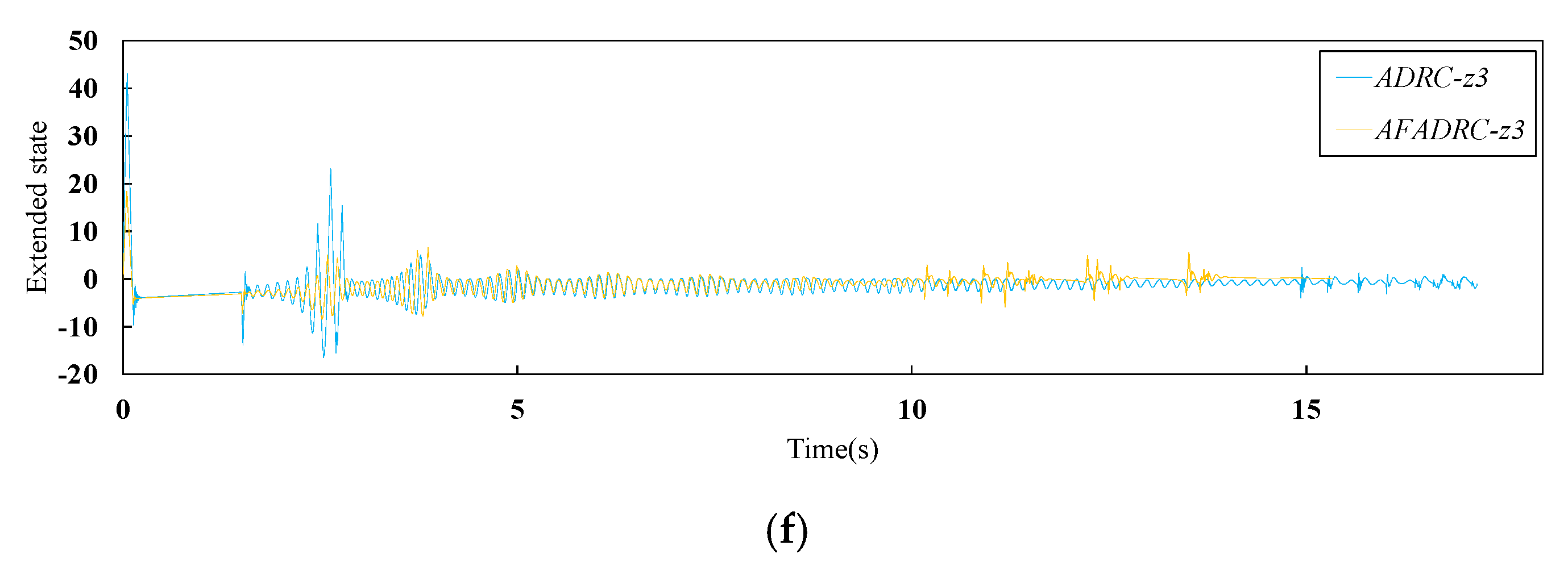
Figure 7f shows that ADRC and AFADRC can effectively estimate the disturbances generated inside the system during braking. It should be noted that AESO and fuzzy logic constantly update the parameters online to improve the estimation and compensation accuracy, which makes AFADRC braking performance better than ADRC.

4.2. Case 2: Actuator LOE Fault and Measurement Noise in Dry Runway Condition

The fault considered here assumes a 20% actuator LOE at 5 s and escalate to 40% LOE at 10 s. The band-limited white noise with noise power 5 × 10 6 is applied to describe the measurement noise. The simulation results are shown in Figure 8 and Table 10. As can be seen in Figure 8a,b, the PID + PBM continuously performs a large braking and releasing operation under the combined effect of fault and disturbance. This makes braking much less efficient and risks dragging and flat tires. Although ADRC can maintain high braking efficiency, the braking time and distance are greatly increased. Moreover, Figure 8c shows that there is a high frequency of wheel slip in the low-speed phase of the aircraft. In contrast, the proposed AFADRC can still efficiently and rapidly control the brakes, since it can remarkably handle the completely unknown uncertainties from both the internal and external. From Figure 8d,f, it can be seen that these uncertainties are estimated fast and accurately based on AESO. Meanwhile, NLSEF with fuzzy logic adaptively adjusts the control law parameters according to the magnitude of the state errors and reconfigures the control to compensate for faults and measurement noise. The comparison between Case 1 and Case 2 illustrates that AFADRC not only ensures the braking performance of fault-free AABS, but also greatly improves the robustness and immunity of AABS in fault-perturbed conditions.

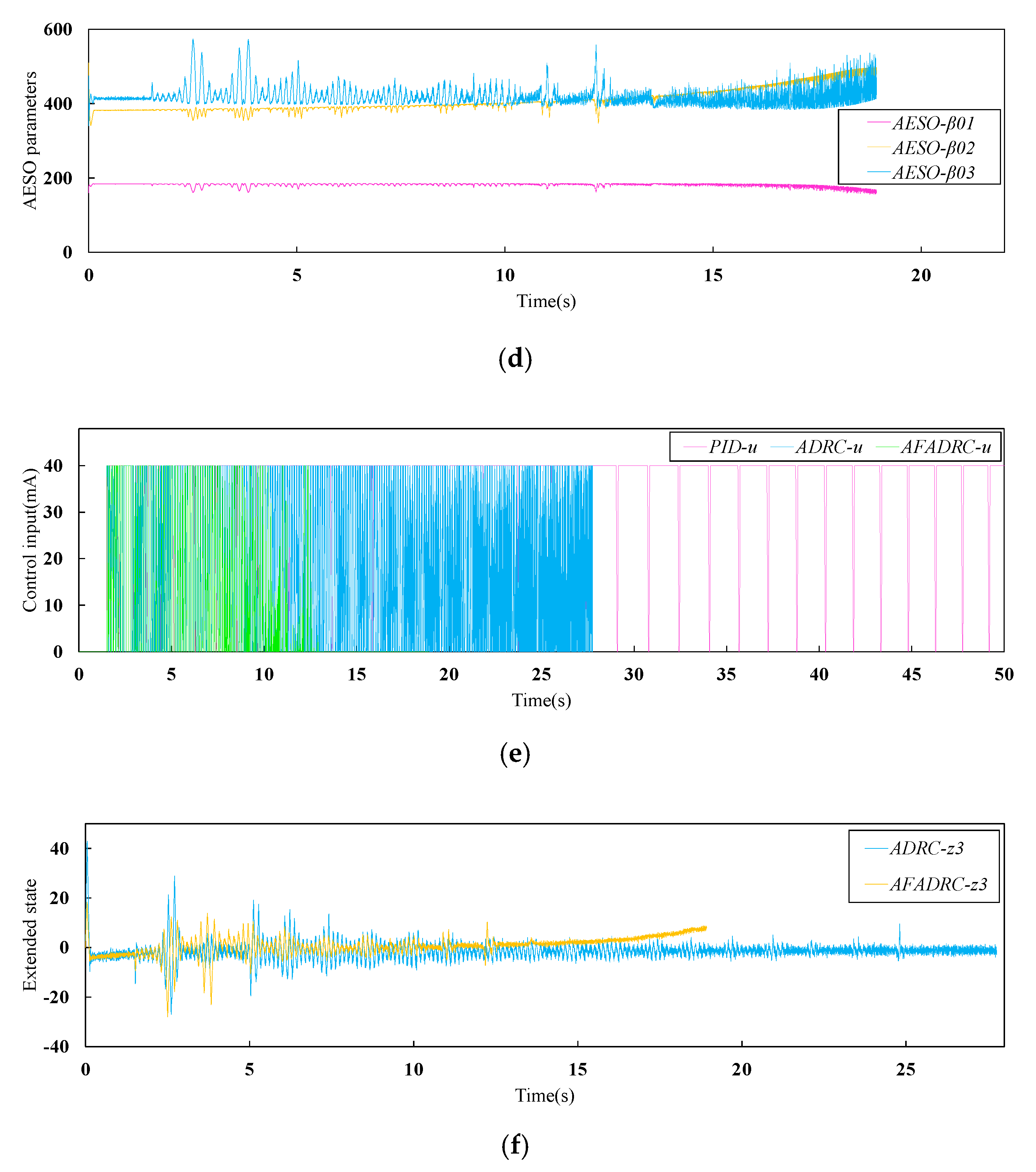
4.3. Case 3: Actuator LOE Fault and Measurement Noise in Mixed Runway Condition

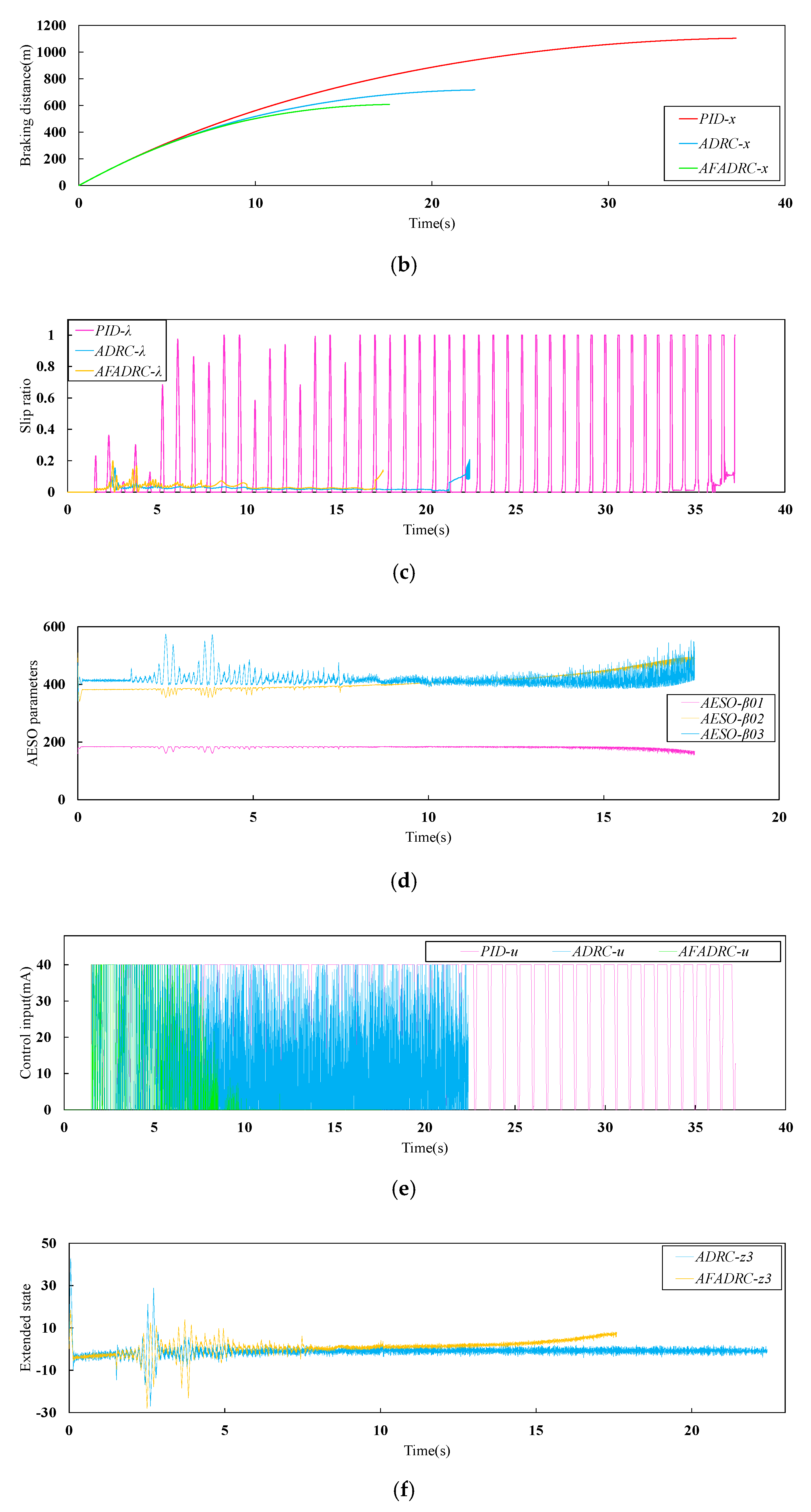
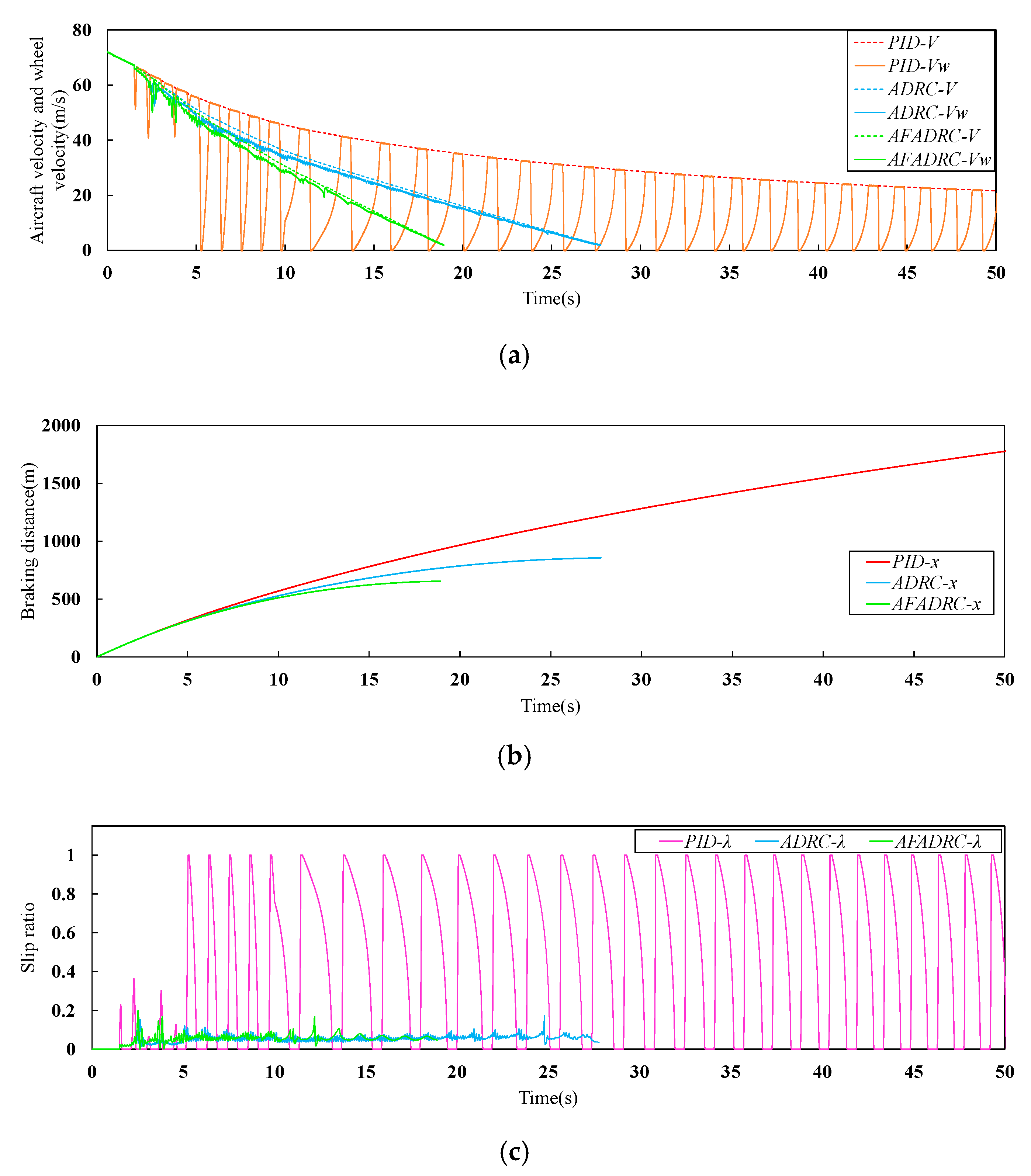
The mixed runway structure is as follows: dry runway in the interval of 0–5 s, wet runway in the interval of 5–10 s, and snow runway after 10 s. Fault and disturbance conditions are the same as Case 2. The simulation results are shown in Figure 9 and Table 11. It can be clearly seen from Figure 9a,b that the PID + PBM control cannot brake the aircraft to stop in a limited time, which may lead to serious consequences. Compared with ADRC, AFADRC can better adapt to the runway changes. Figure 9d shows that AESO can still realize parameter adaption in the mixed runway case. The total perturbations can be accurately estimated: see Figure 9f. Under fault-perturbed conditions, AFADRC can still brake fast with high efficiency, which improves the environmental adaptability and reliability of AABS.

5. Conclusions

In this paper, a novel reconfiguration controller based on AFADRC is proposed to meet the higher performance requirements of AABS in fault-perturbed conditions. An AESO is designed to rapidly and adaptively estimate the states and disturbances of the plant, while an NLSEF incorporating fuzzy logic is developed to actively suppress perturbations and adapt to actuator faults. The proposed reconfiguration controller can perform brake anti-skid control well under faults, perturbations as well as runway changes. The simulation results verify that the proposed method can effectively improve the robustness and environmental adaptability of AABS, which in turn improves the safety and reliability of the whole aircraft. Since ADRC does not limit the specific mathematical form of uncertainty, it poses a great difficulty for the theoretical analysis, which becomes more complicated if a nonlinear mechanism is used. Therefore, the stability of the closed-loop system is difficult to prove. It would be the focus of future work.

Author Contributions

Conceptualization, Z.Z.; Z.Y. and S.L.; Methodology, Z.Z. and Z.Y.; Software, Z.Z.; S.L. and D.Z.; Validation, Z.Z.; Z.Y.; G.Z.; S.L.; S.C. and X.Z.; formal analysis, Z.Z.; Z.Y.; G.Z.; S.L. and D.Z.; investigation, Z.Z.; Z.Y.; S.L.; D.Z.; S.C. and X.Z.; resources, Z.Y.; G.Z.; S.L.; S.C.; X.Z.; data curation, Z.Z.; Z.Y.; G.Z.; S.L.; D.Z.; S.C. and X.Z.; writing-original draft, Z.Z.; S.L.; writing—review & editing, Z.Z. and S.L.; visualization, S.L. and D.Z.; supervision, Z.Z.; Z.Y.; S.L.; D.Z.; S.C. and X.Z.; Project administration, Z.Z.; Z.Y.; S.C. and X.Z.; funding acquisition, Z.Y.; S.C. and X.Z. All authors have read and agreed to the published version of the manuscript.

Funding

This study was supported by the Key Laboratory Projects of Aeronautical Science Foundation of China (201928052006 and 20162852031).

Conflicts of Interest

The authors declare no conflict of interest.

References

  1. Wang, J.; He, C. On improving the performance of aircraft antilock brake system. J. Northwestern Polytech. Univ. 2000, 18, 473–476. [Google Scholar]
  2. Jiao, Z.; Sun, D.; Shang, Y.; Liu, X.; Wu, S. A high efficiency aircraft anti-skid brake control with runway identification. Aerosp. Sci. Technol. 2019, 91, 82–95. [Google Scholar] [CrossRef]
  3. Ming, Z.; Hong, N.; Xiao-hui, W.; Enzhi, Z. Research on modelling and simulation for aircraft anti-skid braking. In Proceedings of the 2008 2nd International Symposium on Systems and Control in Aerospace and Astronautics, Shenzhen, China, 10–12 December 2008; pp. 1–5. [Google Scholar]
  4. Stubbs, S.M.; Tanner, J.A. Review of antiskid and brake dynamics research. In Proceedings of the Aircraft Safety and Operating Problems Conference, NASA Langley Research Center, Wallops Island, VA, USA, 5–7 November 1980; pp. 555–568. [Google Scholar]
  5. Dornheim, M.A. Electric brakes tested on F-16. Aviat. Week Space Technol. 1999, 150, 51. [Google Scholar]
  6. Chen, M.; Liu, W.; Ma, Y.; Wang, J.; Xu, F.; Wang, Y. Mixed slip-deceleration PID control of aircraft wheel braking system. IFAC-PapersOnLine 2018, 51, 160–165. [Google Scholar] [CrossRef]
  7. Qiu, Y.; Liang, X.; Dai, Z. Backstepping dynamic surface control for an anti-skid braking system. Control Eng. Pract. 2015, 42, 140–152. [Google Scholar] [CrossRef]
  8. Mirzaei, A.; Moallem, M.; Dehkordi, B.M.; Fahimi, B. Design of an Optimal Fuzzy Controller for Antilock Braking Systems. IEEE Trans. Veh. Technol. 2006, 55, 1725–1730. [Google Scholar] [CrossRef]
  9. Lin, C.M.; Hsu, C.F. Self-learning fuzzy sliding-mode control for antilock braking systems. IEEE Trans. Control Syst. Technol. 2003, 11, 273–278. [Google Scholar] [CrossRef] [Green Version]
  10. Wang, W.Y.; Li, I.H.; Chen, M.C.; Su, S.F.; Hsu, S.B. Dynamic slip-ratio estimation and control of antilock braking systems using an observer-based direct adaptive fuzzy–neural controller. IEEE Trans. Ind. Electron. 2008, 56, 1746–1756. [Google Scholar] [CrossRef]
  11. Chen, X.; Dai, Z.; Lin, H.; Qiu, Y.; Liang, X. Asymmetric barrier Lyapunov function-based wheel slip control for antilock braking system. Int. J. Aerosp. Eng. 2015, 2015, 1–10. [Google Scholar] [CrossRef] [Green Version]
  12. Li, F.B.; Huang, P.M.; Yang, C.H.; Liao, L.Q.; Gui, W.H. Sliding mode control design of aircraft electric brake system based on nonlinear disturbance observer. Acta Autom. Sin. 2020. [Google Scholar] [CrossRef]
  13. Jiao, Z.; Liu, X.; Shang, Y.; Huang, C. An integrated self-energized brake system for aircrafts based on a switching valve control. Aerosp. Sci. Technol. 2017, 60, 20–30. [Google Scholar] [CrossRef]
  14. Shang, Y.X.; Liu, X.C.; Jiao, Z.X.; Wu, S. A novel integrated self-powered brake system for more electric aircraft. Chin. J. Aeronaut. 2018, 31, 976–989. [Google Scholar] [CrossRef]
  15. Sun, D.; Jiao Z., X.; Shang, Y.X.; Wu, S.; Liu, X.C. High-efficiency aircraft antiskid brake control algorithm via runway condition identification based on an on-off valve array. Chin. J. Aeronaut. 2019, 32, 2538–2556. [Google Scholar] [CrossRef]
  16. Zhang, Z.; Yang, Z.; Xiong, S.; Chen, S.; Liu, S.; Zhang, X. Simple Adaptive Control-Based Reconfiguration Design of Cabin Pressure Control System. Complexity 2021, 2021, 6635571. [Google Scholar]
  17. Calise, A.J.; Lee, S.; Sharma, M. Development of a reconfigurable flight control law for tailless aircraft. J. Guid. Control Dyn. 2001, 24, 896–902. [Google Scholar] [CrossRef]
  18. Han, Y.G.; Liu, Z.P.; Dong, Z.C. Research on Present Situation and Development Direction of Aircraft Anti-Skid Braking System; China Aviation Publishing & Media CO., LTD.: Xi’an, China, 2020; Volume 5, pp. 525–529. [Google Scholar]
  19. Han, J. From PID to active disturbance rejection control. IEEE Trans. Ind. Electron. 2009, 56, 900–906. [Google Scholar] [CrossRef]
  20. Zheng, Q.; Gao, Z. On practical applications of active disturbance rejection control. In Proceedings of the 29th Chinese Control Conference, Beijing, China, 29–31 July 2010; pp. 6095–6100. [Google Scholar]
  21. Zhang, Z.; Yang, Z.; Duan, Y.X.; Liao, L.W.; Lu, K.W.; Zhang, Q.Y. Active disturbance rejection control method for actively deformable quadrotor. Control Theory Appl. 2021, 38, 444–456. [Google Scholar]
  22. Sira-Ramírez, H.; Linares-Flores, J.; García-Rodríguez, C.; Contreras-Ordaz, M.A. On the control of the permanent magnet synchronous motor: An active disturbance rejection control approach. IEEE Trans. Control Syst. Technol. 2014, 22, 2056–2063. [Google Scholar] [CrossRef]
  23. Chang, X.; Li, Y.; Zhang, W.; Wang, N.; Xue, W. Active disturbance rejection control for a flywheel energy storage system. IEEE Trans. Ind. Electron. 2014, 62, 991–1001. [Google Scholar] [CrossRef]
  24. Guo, B.Z.; Jin, F.F. The active disturbance rejection and sliding mode control approach to the stabilization of the Euler–Bernoulli beam equation with boundary input disturbance. Automatica 2013, 49, 2911–2918. [Google Scholar] [CrossRef]
  25. Xue, W.; Bai, W.; Yang, S.; Song, K.; Huang, Y.; Xie, H. ADRC with adaptive extended state observer and its application to air–fuel ratio control in gasoline engines. IEEE Trans. Ind. Electron. 2015, 62, 5847–5857. [Google Scholar] [CrossRef]
  26. Pu, Z.; Yuan, R.; Yi, J.; Tan, X. A class of adaptive extended state observers for nonlinear disturbed systems. IEEE Trans. Ind. Electron. 2015, 62, 5858–5869. [Google Scholar] [CrossRef]
  27. Roman, R.C.; Precup, R.E.; Petriu, E.M. Hybrid data-driven fuzzy active disturbance rejection control for tower crane systems. Eur. J. Control 2021, 58, 373–387. [Google Scholar] [CrossRef]
  28. Hosseinzadeh, M.; Sadati, N.; Zamani, I. H∞ disturbance attenuation of fuzzy large-scale systems. In Proceedings of the 2011 IEEE International Conference on Fuzzy Systems, Taipei, Taiwan, 27–30 June 2011; pp. 2364–2368. [Google Scholar]
  29. Shahnazi, R.; Akbarzadeh-T, M.R. PI adaptive fuzzy control with large and fast disturbance rejection for a class of uncertain nonlinear systems. IEEE Trans. Fuzzy Syst. 2008, 16, 187–197. [Google Scholar] [CrossRef]
  30. Chen, Z.; Qin, B.; Sun, M.; Sun, Q. Q-learning-based parameters adaptive algorithm for active disturbance rejection control and its application to ship course control. Neurocomputing 2020, 408, 51–63. [Google Scholar] [CrossRef]
  31. Qi, X.H.; Li, J.; Han, S.T. Adaptive active disturbance rejection control and its simulation based on BP neural network. Acta Armamentarii 2013, 34, 776–782. [Google Scholar]
  32. Roman, R.C.; Precup, R.E.; Petriu, E.M.; Dragan, F. Combination of data-driven active disturbance rejection and Takagi-Sugeno fuzzy control with experimental validation on tower crane systems. Energies 2019, 12, 1548. [Google Scholar] [CrossRef] [Green Version]
  33. Gai, J.T.; Huang, S.D.; Huang, Q.; Li, M.Q.; Wang, H.; Luo, D.R.; Wu, X.; Liao, W. A new fuzzy active-disturbance rejection controller applied in PMSM position servo system. In Proceedings of the 2014 17th International Conference on Electrical Machines and Systems (ICEMS), Hangzhou, China, 22–25 October 2014; pp. 2055–2059. [Google Scholar]
  34. Hua, X.; Huang, D.; Guo, S. Extended state observer based on ADRC of linear system with incipient fault. Int. J. Control Autom. Syst. 2020, 18, 1425–1434. [Google Scholar] [CrossRef]
  35. Guo, Y.; Jiang, B.; Zhang, Y. A novel robust attitude control for quadrotor aircraft subject to actuator faults and wind gusts. IEEE/CAA J. Autom. Sin. 2017, 5, 292–300. [Google Scholar] [CrossRef]
  36. Liu, W.S.; Xu, F.R.; Ma, Y.Z.; Chen, M.Q. Optimization Design of Aircraft Anti-Skid Braking Controller. Comput. Simul. 2016, 33, 93–98. [Google Scholar]
  37. Zou, M.Y. Research on a Novel Control Law Design and Simulation for Aircraft Anti-Skid Braking System. Master’s Thesis, Northwestern Polytechnical University, Xian, China, 2005. [Google Scholar]
  38. Pacejka, H.B.; Bakker, E. The magic formula tyre model. Veh. Syst. Dyn. 1992, 21, 1–18. [Google Scholar] [CrossRef]
  39. Huang, Y.; Xue, W. Active disturbance rejection control: Methodology and theoretical analysis. ISA Trans. 2014, 53, 963–976. [Google Scholar] [CrossRef] [PubMed]
  40. Mei-Ling, W.; Nian-Ping, W.; Xiao, L. Improvement and application of BPNN algorithm. Comput. Eng. Appl. 2009, 45, 47–48. [Google Scholar]
  41. Zhao, J.Y.; Li, J.B.; Zheng, R.R. Application of adaptive learning rate method in power transformer fault diagnosis. J. Jilin Univ. (Inf. Sci. Ed.) 2008, 26, 415–420. [Google Scholar]
  42. Yan, Z.L.; Xiao, Y.; Lu, B. Study on Anti-Skid System Efficiency of Civil Aircraft. Sci. Technol. Vis. 2017, 4, 1–3. [Google Scholar]
Figure 1. Force diagram of aircraft fuselage.
Actuators 10 00201 g001
Figure 2. Force analysis diagram of a single main wheel.
Actuators 10 00201 g002
Figure 3. Overall components of aircraft anti-skid braking system.
Actuators 10 00201 g003
Figure 4. Structure of AFADRC.
Actuators 10 00201 g004
Figure 5. Structure of AESO.
Actuators 10 00201 g005
Figure 6. Brake efficiency scheme.
Actuators 10 00201 g006
Figure 7. Case 1 simulation results: (a) aircraft velocity and wheel velocity; (b) breaking distance; (c) slip ratio; (d) AESO parameters; (e) control input; (f) extended state.
Actuators 10 00201 g007aActuators 10 00201 g007b
Figure 8. Case 2 simulation results: (a) aircraft velocity and wheel velocity; (b) breaking distance; (c) slip ratio; (d) AESO parameters; (e) control input; (f) extended state.
Actuators 10 00201 g008aActuators 10 00201 g008b
Figure 9. Case 3 simulation results: (a) aircraft velocity and wheel velocity; (b) breaking distance; (c) slip ratio; (d) AESO parameters; (e) control input; (f) extended state.
Actuators 10 00201 g009aActuators 10 00201 g009b
Table 1. Parameters for aircraft fuselage dynamics.
NameDescriptionValue
x Aircraft taxiing distance
y Amount of change in height of center of gravity
θ Aircraft pitch angle
H Center of gravity height
V Aircraft speed
T 0 Engine force
F x Aerodynamic drag
F y Aerodynamic lift
F s Parachute drag
f 1 Braking friction force between main wheel and ground
f 2 Braking friction force between front wheel and ground
N 1 Main wheel support force
N 2 Front wheel support force
M Mass of the aircraft 1761 kg
G Aircraft weight 17,256 N
I Fuselage inertia 4000 kg sec 2 m
h t Distance between engine force lineand center of gravity 0.1 m
h s Distance between parachute drag lineand center of gravity 0.67 m
a Distance between main wheel and center ofgravity 1.076 m
b Distance between front wheel and center ofgravity 6.727 m
T 0 Intimal engine force 426 kg
K v Velocity coefficient of engine 1 kg sec / m
ρ Air density 0.12492 kg sec 2 / m 4
C x Aerodynamic drag coefficient 0.1027
C x s Parachute drag coefficient 0.75
S Wing area 50.88 m 2
S s Parachute area 20 m 2
C y Aerodynamic lift coefficient 0.6
Table 2. Parameters of the buffer.
NameDescriptionValue
X 1 Main buffer compression
X 2 Front buffer compression
K 1 Main buffer stiffness coefficient 42,529
K 2 Front buffer stiffness coefficient 2500
C 1 Main buffer damping coefficient 800
C 2 Front buffer damping coefficient 800
Table 3. Parameters of the landing gear lateral stiffness model.
NameDescriptionValue
d a Navigation vibration displacement
d V Navigation vibration speed
K 0 Dynamic stiffness coefficient 536 , 000
ξ Equivalent model damping ratio 0.2
W n Equivalent model natural frequency 60 Hz
Table 4. Parameters of the main wheel.
NameDescriptionValue
ω Main wheel angular velocity
ω ˙ Main wheel angular acceleration
V w Main wheel line speed
R g Main wheel rolling radius
J Main wheel inertia 1.855 kg sec 2 m
R Wheel free radius 0.4 m
k σ Tire compression coefficient 1.07 × 10 5 m / kg
n Number of main wheels 4
Table 5. Parameters of combination coefficient model.
Runway Status D C B
Dry Runway 0.85 1.5344 14.5
Wet Runway 0.40 2.0 8.2
Snow Runway 0.28 2.0875 10
Table 6. Parameters of the hydraulic servo system.
NameDescriptionValue
K s v Servo valve gain 2.5 × 10 5
ω s v Servo valve natural frequency 17.7074 rad / s
ξ s v Servo valve damping ratio 0.36
K p Pipe gain 1
T p Pipe equivalent time constant 0.01
μ m c Friction coefficient of brake material 0.23
N m c Number of friction surfaces 4
R m c Effective brake friction radius 0.142 m
Table 7. Fuzzy rule table.
e 2 NBNSZOPSPB
e 1
NBPB/PSPS/NSPS/NBPS/NBZO/PS
NSPS/PSPS/NSPS/NBZO/NSNS/ZO
ZOPS/ZOPS/NSZO/NSNS/NSNS/ZO
PSPS/PBZO/ZONS/ZONS/ZONS/PB
PBZO/PBNS/PSNS/PSNS/PSNS/PB
Table 8. Parameters of AFADRC.
NameValueNameValue
T D r 0.001 A E S O β 03 _ I N T 800
T D h 1 A E S O b e 0.08
A E S O δ 0.001 N L S E F δ 0 0.001
A E S O β 01 _ I N T 300 N L S E F k ˜ 1 5
A E S O β 02 _ I N T 600 N L S E F k ˜ 2 5
Table 9. AABS performance index in Case 1.
Performance IndexPID + PBMADRCAFADRC
Breaking distance (m) 872.04 635.19 599.31
Breaking time (s) 22.293 17.167 15.327
Braking efficiency (%) 76.4 98.1 99.6
Table 10. AABS performance index in Case 2.
Performance IndexPID + PBMADRCAFADRC
Breaking distance (m) 1102.984 715.87 607.14
Breaking time (s) 37.223 22.424 17.591
Braking efficiency (%) 43.6 92.5 99.3
Table 11. AABS performance index in Case 3.
Performance IndexPID + PBMADRCAFADRC
Breaking distance (m) 854.8565 653.7929
Breaking time (s) 27.767 18.927
Braking efficiency (%) 89.3 96.6
Publisher’s Note: MDPI stays neutral with regard to jurisdictional claims in published maps and institutional affiliations.

